Article

Design Optimization and Experimental Verification of Permanent Magnet Synchronous Motor Used in Electric Compressors in Electric Vehicles

1
Department of Automotive Engineering, Honam University, 417 Eodeung-daero, Gwangsan-gu, Gwangju 62399, Korea
2
Department of Mechanical Design Engineering, Wonkwang University, 460 Iksan-daero, Iksan-si, Jeollabuk-do 54538, Korea
*
Author to whom correspondence should be addressed.
Appl. Sci. 2020, 10(9), 3235; https://doi.org/10.3390/app10093235
Submission received: 9 April 2020 / Revised: 28 April 2020 / Accepted: 3 May 2020 / Published: 6 May 2020

Abstract

:

Featured Application

Optimal design of permanent magnet synchronous motors (PMSMs) used in electric compressors in electric vehicles. Based on the proposed optimization method, the efficiency and cogging torque characteristics of the PMSM can be improved.

Abstract

In this study, a shape design optimization method is proposed to improve the efficiency of a 3 kW permanent magnet synchronous motor (PMSM) used in an electric compressor intended for use in an electric vehicle. The proposed method improves the efficiency performance of the electric compressor by improving the torque characteristics of the initial PMSM model. The dimensions of the rotor were set as the design variables and were chosen to maximize efficiency and reduce cogging torque. During the determination of the design points with conventional Latin hypercube design, the experimental points may be closely related to each other. Therefore, the optimal Latin hypercube design was used to optimally distribute the experimental points evenly and improve the space filling characteristics. The Kriging model was used as an interpolation model to predict the optimal values of the design variables. This allowed the formulation of more accurate prediction models with multiple design variables, complex reactions, or nonlinearities. A genetic algorithm was used to identify the optimal solution for the design variables. It was used to satisfy the objective function and to determine the optimal design variables based on established constraints. The optimal design results obtained based on the proposed shape optimization method were confirmed by finite element analyses. For practical verification, the optimal model of the prototype PMSM of an electric compressor was manufactured, and a 1.5% improvement in its efficiency performance was confirmed based on an experimental dynamometer test.

1. Introduction

As the environmental pollution of internal combustion engine vehicles becomes serious, interest in eco-friendly vehicles and hybrid electric vehicles (HEVs) are increasing worldwide [1]. Among them, electric vehicles (EVs) are in the spotlight as pollution-free automobiles that reduce fuel efficiency [2] and have no harmful emissions because they use only electric energy in the system instead of the engine of an internal combustion engine [3]. Therefore, EV has been proposed as one of the methods to solve fossil fuel depletion and environmental problems, and research on it has been actively conducted worldwide [4].
Recently, the PMSM has been used in parts for electric vehicles because it has excellent efficiency characteristics compared with induction motors [5]. PMSM is a structure in which a permanent magnet is embedded in the iron core of the rotor, and the magnetic flux weakening operation area can be widened depending on the difference in inductance of the d-q axis [6]. Because of these advantages, it is widely used in EV or HEV where variable speed operation is required [7].
An electric compressor for air conditioning of electric vehicles has been developed, and by applying high-efficiency PMSM to the compressor, it has the advantage of increasing fuel efficiency regardless of the vehicle’s driving speed [8].
Optimal design is essential to meet the various design requirements of PMSM. Optimal design is a method of finding the value of a design variable and obtaining an optimal solution within a limited design area [9]. The previous researches on the optimal design of PMSM can be divided into two categories.
First, there are studies using the magnetic equivalent circuits (MEC) model [10,11]. In [10], it was proposed as a study on optimization using MEC model. It has been reported that the MEC optimization method combined with the optimization algorithm can optimize the volume and energy loss of PMSM. In addition, a novel MEC model of PMSM was developed to obtain maximum efficiency, minimum weight and price [11]. However, MEC-based design has a problem in that it is difficult to accurately consider the nonlinearity of parameters.
Second, there are studies that combine numerical analysis methods of electrical devices such as finite element analysis (FEA) with optimal design algorithms [12,13]. FEA was performed to take into account the nonlinearity of permanent magnets and electrical steel sheets, which are difficult to consider in MEC.
In [12], an optimal design of PMSM based on dynamic characteristics and finite element analysis of PMSM was performed. Design variables that influenced the efficiency characteristics of PMSM were selected and the efficiency and response characteristics were improved through experiments.
In [13], the authors announced the optimization design process of PMSM for electric compressors of air conditioners applied to electric vehicles and hybrid vehicles. Research on the optimal design of PMSM using the response surface method has been carried out. In particular, the response surface method is often used in the optimization design of permanent magnet motors. The response surface method typically uses a second order polynomial regression model. However, it is difficult to accurately predict the optimum value because the response surface method becomes highly nonlinear and yields an unstable high-order prediction function.
As a similar study related to PMSM, the rated efficiency was improved through the optimum design of 110 W small brushless direct current (BLDC) motor [14]. In addition, a study was conducted to improve the performance of the electric variable valve timing system for improving fuel efficiency and emission of automobiles [15].
Cogging torque is one of the most representative components of torque ripple in PMSM. This phenomenon can be a critical issue to automotive applications that need precision control of the PMSM and are sensitive to noise and vibration. Therefore, recently, studies to improve efficiency and reduce cogging torque have been actively conducted, and mainly focused on reducing the cogging effect by adjusting the combination of pole slot number, pole arc, and core shape [16,17].
Furthermore, the study of [18] performed multi-purpose shape optimization of PMSM based on FEA and particle swarm optimization algorithms. Unlike the existing methods, the proposed rule of start point selection takes an advantage of minimizing the search time.
A study has been conducted on the multi-purpose optimized design PMSM of fractional slotted windings [19]. The optimization results demonstrated the accuracy of the proposed model with comparison to numerical models such as FEA, but with much faster computational performance which makes it much more suitable to be used in evolutionary optimization design approaches.
Most of the previous studies were applied to the optimal design using metamodels created in one way [20,21]. In general, FEA’s design of experiment (DOE) consists of a modeling process using CAD tools, an FEA analytical condition setting process, a FEA process, and a post-process for extracting and configuring results. A lot of DOE has to be done to get reliable and optimal design results.
As a related study, Taguchi method was used to optimize the efficiency and cogging torque of BLDC motors used in automotive electric oil pumps. However, to obtain DOE results, 336 FE analyses for five design variables were required [22].
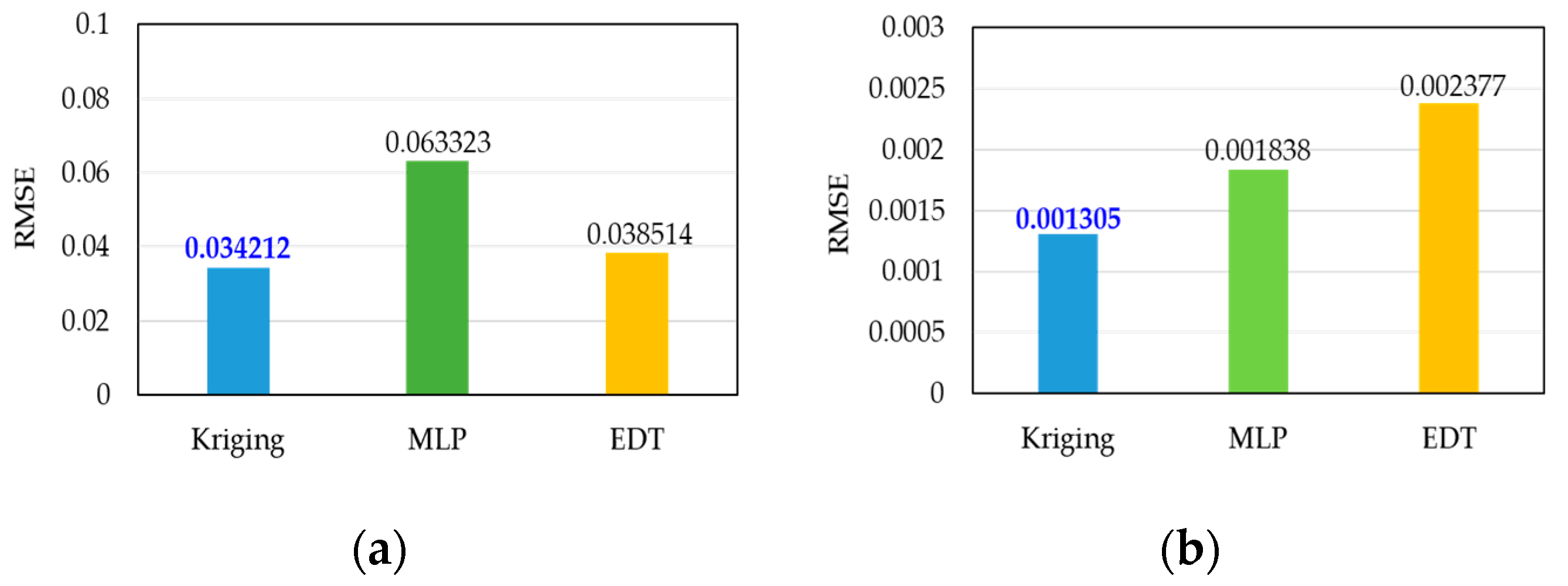
This study differs from previous studies given that five design variables were selected for the DOE and 54 experiments were performed. To improve the efficiency of the design variable distribution, the optimal Latin hypercube design (OLHD) [23,24] was used with an equal number of levels for all the design variables that has a better fill performance than Latin hypercube design (LHD) [25]. Numerous studies have been published on metamodeling conducted based on the application of a single method [26,27]. However, there are suitable metamodels for each optimal design problem. Correspondingly, the metamodels need to be written and compared in various ways. Given that the prediction performance of the metamodel affects the reliability of the optimal design, it is necessary to evaluate the accuracy of each metamodel. Therefore, we evaluated three representative metamodels, including Kriging [28], multilayer perceptron (MLP) [29], and ensemble of decision tree (EDT) [30], and compared the metamodeling results. The predicted performances of the metamodels were evaluated and compared based on the root-mean-square error (RMSE) test, the results, and Kriging was selected as the best metamodel. In this paper, Kriging model can evaluate models with many design variables, complex responses, or strong nonlinearities more accurately.
The genetic algorithm (GA) [31] was used for the determination of the optimal design variables based on the objective functions and constraints set for the optimization.
To verify the validity of the proposed optimization design results, the characteristics of the initial and the optimal models (back-electromotive force (EMF), cogging torque, and torque ripple) were evaluated based on finite element analyses, and the results were compared. To verify feasibility, the proposed optimization method was applied to the design of a 3 kW PMSM used in an electric compressor, and the method’s performance was compared with the results obtained from the initial model with finite element analysis. Finally, prototype PMSMs were fabricated and dynamometer tests were performed to confirm the suitability of the proposed shape optimization design.

2. PMSM for Electric Compressor

The compressor of a vehicle operated by a conventional internal combustion engine is driven by the driving force of the engine. Correspondingly, when the compressor is operating, the output power of the engine is reduced. In addition, given that the engine contains various mechanical components, unnecessary power consumptions occur that lead to increased fuel consumption. To solve this problem, an electric compressor driven by a motor was developed. The electric compressor has an advantage in that it can be mounted on an electric vehicle based on the utilization of the energy of the high-voltage battery of the electric vehicle. The system used to cool an electric vehicle is composed of a high-voltage battery, an inverter, and an electric compressor, and is shown in Figure 1.
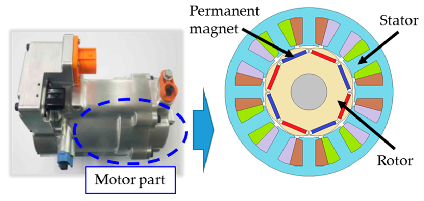
Figure 2 shows the shape of an initial PMSM model used for an electric compressor. The PMSM selected for this study has an interior permanent magnet (IPM) type with an 8 pole/12 slot structure with a concentrated winding method in consideration of vibration and noise. Initial designs have been established to satisfy the given specifications. The current density of the stator winding is designed to be less than 7 Arms/mm2 at maximum speed. The reference temperature condition is 20 °C. The specifications of the initial model are listed in Table 1.

3. Design Optimization

3.1. Rotor Shape Optimization Process

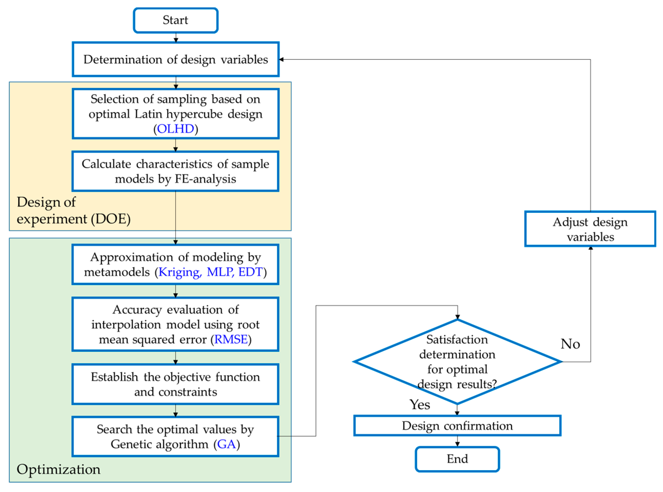
The proposed optimization process was performed by taking into account the rotor shape of the PMSM as a design variable and by taking into account the efficiency and cogging torque. The proposed optimization process for the design of PMSM is illustrated in Figure 3.
The proposed optimization process is as follows. Depending on the design specifications of the initial model, design variables are selected that improve the efficiency and reduce cogging torque characteristics. To execute the DOE, the design variables were determined using OLHD. The efficiency and cogging torque characteristics of the sampling models were calculated based on finite element analyses. To ensure the accuracy of the DOE results, metamodeling of multipurpose functions and constraints used the following three techniques: Kriging model, MLP, and EDT. For the evaluation of the predictive performance of the metamodel, the best approximation modeling method was adopted based on the comparison of the results of RMSE. The objective functions and constraints were set to achieve the required target specifications. To obtain the values of the design variables of the optimal model, metamodeling results were obtained with the optimal GA algorithm. Finally, if the target design result does not appear, the optimization process is restarted by adjusting the design variables.
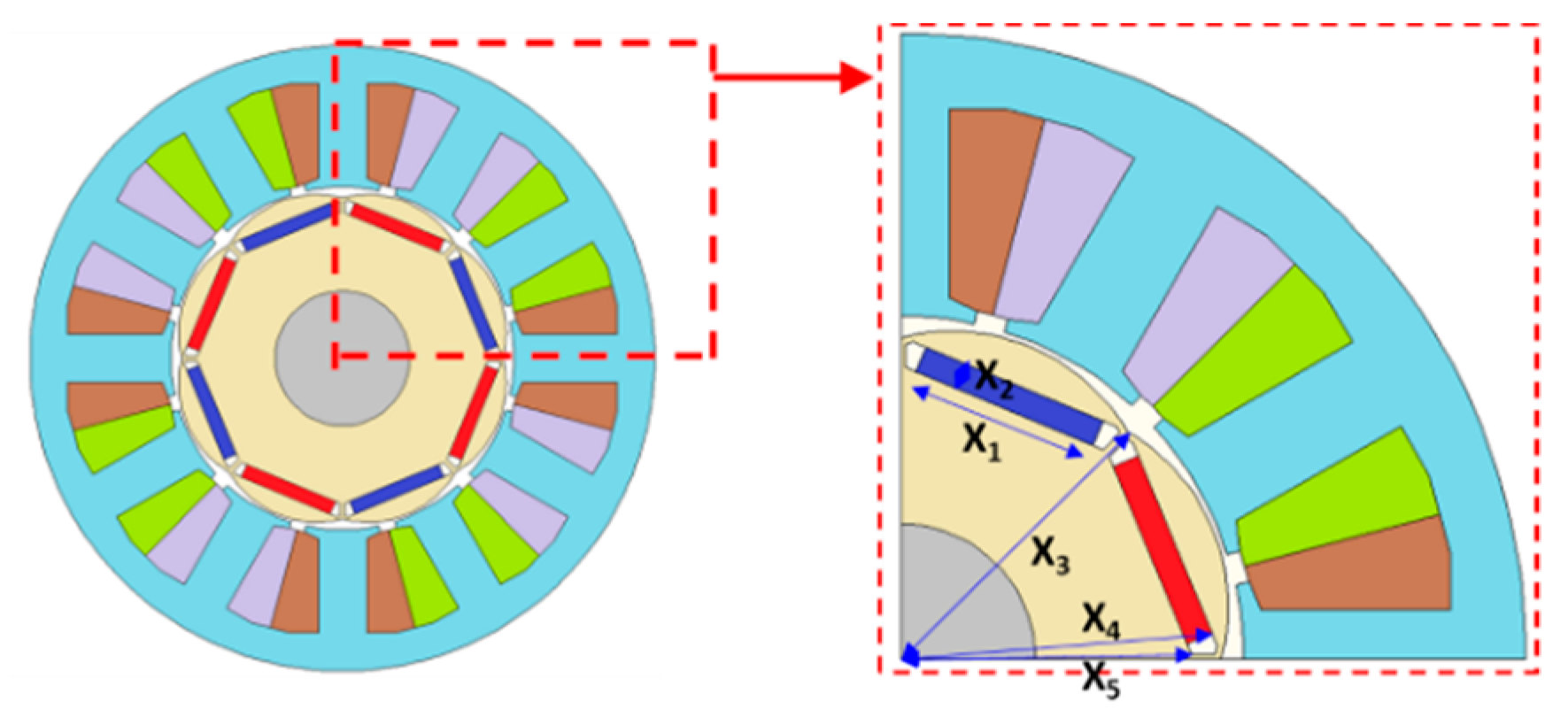
According to this optimization process, the mechanical dimensions of the stator and rotor, i.e., the diameter of the core and the stack length, were fixed. Five design variables of the rotor shape were selected as shown in Figure 4.
Table 2 shows the range of the five design variables used for the optimization of the rotor shape of the PMSM. X1 is the magnet length, X2 is the magnet width, X3 is the distance between the center and the inner diameter of rotor, X4 is the distance between the center and the magnet, and X5 is the distance between the center and the barrier. These design variables were chosen to optimize the rotor shape because they affect the efficiency and cogging torque of the PMSM. In addition, the ranges of the upper and lower limits for each design variable are also listed. The design variables and ranges were determined based on the consideration of the PMSM’s manufacturability.
The objective function used to maximize efficiency is expressed by Equation (1). In addition, the constraint that should be lower than the cogging torque of the initial model of 0.3479 Nm, as indicated by Equation (2).
  • Objective function:
Maximize the efficiency.
  • Constraints:
Cogging torque < 0.3479 Nm

3.2. Design of Experiment

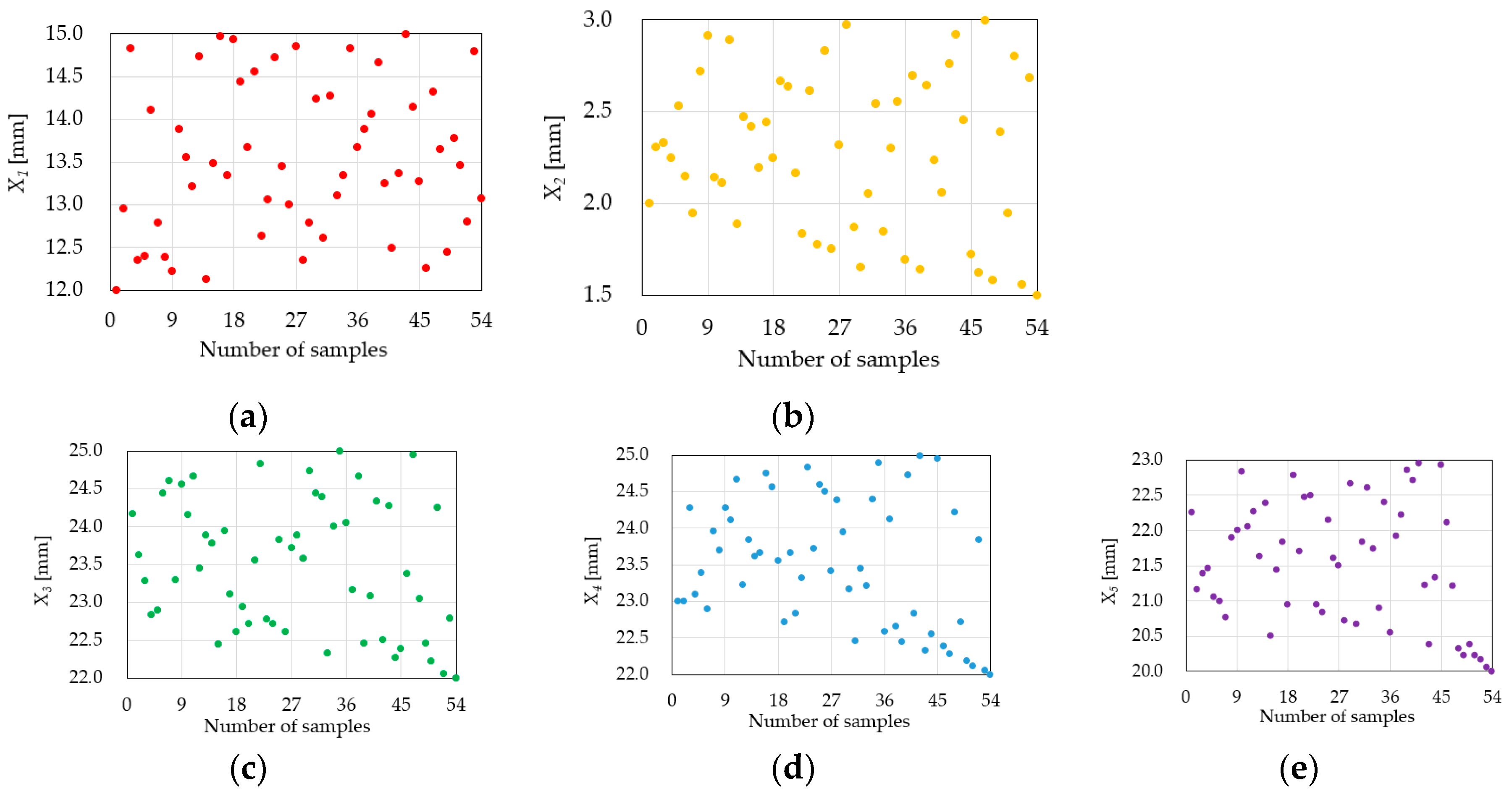
Sampling points were selected with the OLHD. OLHD has the advantage of distributing the experimental points evenly using optimal conditions. This technique has improved projection properties and spatial fill properties compared with the existing LHD. The number of experimental points was determined based on consideration of the range of design variables listed in Table 2. The total number of samples was determined to be 54. This number was chosen to ensure that a sufficient number of experimental points existed for all five design variables. Figure 5 shows the sample distribution maps of all the design variables. The sample points were chosen so that there were no overlapping points.
The efficiency and cogging torque characteristics of the samples selected by OLHD were calculated via FE analyses, and are listed in Appendix A. The efficiency and cogging torque characteristics of each sample were obtained based on two-dimensional (2D) FE analyses.

3.3. Metadmodeling

Based on the DOE results described in the previous section, we created a metamodel for the objective function and constraint. Most of the existing studies have proposed metamodels, but accuracy evaluations were not performed. Furthermore, searches for optimal values of design variables have been conducted. Therefore, to evaluate the metamodel accuracy, the best metamodel was selected by comparing the RMSE test outcomes according to the efficiency and cogging torque characteristics.
The Kriging model [28], an interpolation model type, passes the test points accurately and is suitable for approximation without random errors. Therefore, a numerically robust model was provided. The estimation equation for the Kriging model was defined to eliminate bias, thus minimizing error variance.
MLP [29] is a type of deep learning algorithm and has the advantage of expressing a nonlinear relationship between input and output variables. In particular, metamodels can be created even when there are plenty of data. However, if there are many parameters that depend on the know-how of the user, accuracy may be deteriorated and training time may be required.
The EDT [30] has a feature that allows the generation of multiple decision trees (DTs) and the prediction of an output value as the average value of all the outputs predicted by each DT for a specific input value. The instability and performance variance of the DT model were reduced compared with the use of a single DT. Additionally, the predictive power was improved and the performance was excellent in large datasets. However, parameters (depth, number of DTs, etc.) must be determined in advance. As the depth of DT becomes deeper, the DT model becomes complicated and leads to an increase of the calculation complexity. Figure 6 shows the conceptual diagram of the Kriging model, MLP, and EDT used for metamodeling in this study.
Given that the predictive performance of the metamodel affects the reliability of the optimal design, the predicted performance was compared based on the RMSE test. The RMSE values should be used to evaluate the accuracy of the interpolation model. The predictive performance of the metamodel was evaluated based on the RMSE test and was calculated according to Equation (3) [32].
RMSE = 1 n t e s t i = 1 n t e s t [ y ( X i ) y ^ ( X i ) ] 2
where ntest is the number of test points for metamodel validation, y(Xi) is the value of the real function, and yˆ(Xi) is the value of the metamodel.
The predicted performance of the metamodel was evaluated as an output variable of efficiency and cogging torque through the RMSE test. The comparison of the RMSE test results of the metamodels for the objective function is shown in Figure 7. The lower the value of the RMSE is, the better the predictive performance will be. As shown in Figure 7, the Kriging model yielded the best prediction performance as a metamodel of efficiency and cogging torque. However, if the number of design variables, objective functions, and constraints are different, different metamodels for each characteristic may yield the best predictive performances. In this study, Kriging metamodels that yielded the best predictive performances for each of the output variables were selected for optimal design.

3.4. Global Searching with the GA

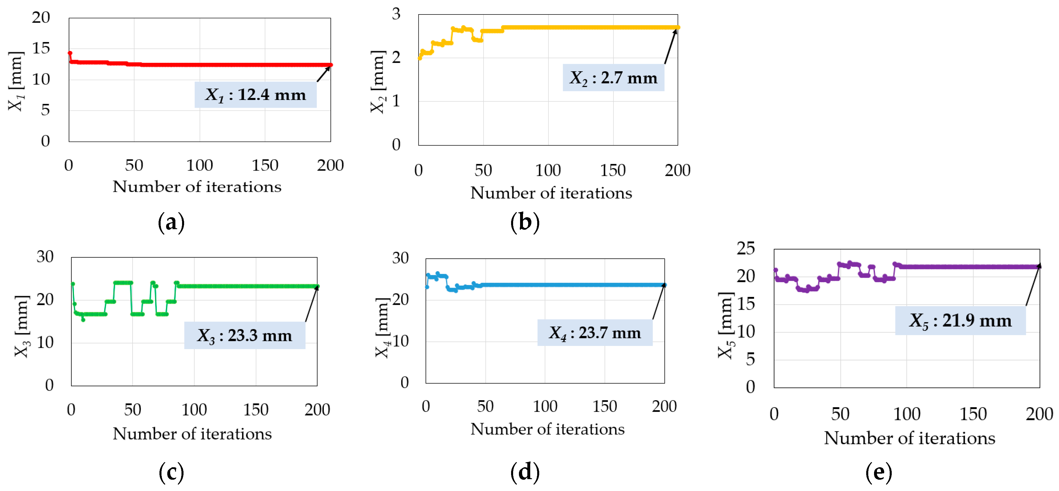
GA was developed to investigate optimal design variables with an approximate model. GA is commonly used to create solutions for optimization and search problems, thus relying on inspired in vivo operators, such as mutation, crossover, and selection [31]. GA was used to determine the optimal design variables based on the objective function mentioned above and constraints set for optimal design. Figure 8 shows the respective 200 iteration convergence profiles of each of the five design variables investigated in this study. The convergence yielded design variables that were adjusted for optimal efficiency and cogging torque.
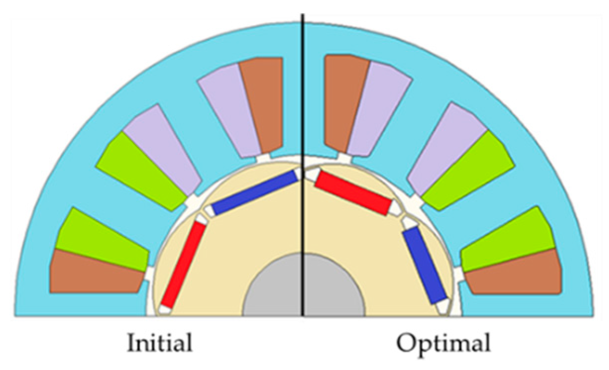
Table 3 compares the values of the initial and optimal model design variables. The shape of the optimal model was determined by the proposed optimization process. Figure 9 illustrates the comparison between the initial and optimal models.

4. Verification of Simulations and Experiments

4.1. Simulation Results

In this study, the electromagnetic analyses of the no-load and load characteristics of PMSM were performed to compare the characteristics of the initial and the optimal models. In general, in the case of an electric motor, magnetic properties occur almost linearly except for the electrical part of the end-winding along the stacking length in the axial direction. To evaluate the validity of the analytical model and the optimization design procedure presented in the previous section, the characteristics of PMSM were predicted with two-dimensional FE analysis based on the electromagnetic field simulation software JMAG-Designer (v18.0, JSOL Corporation, Tokyo, Japan). To ensure analytical accuracy, model geometries used high-quality meshes with 35,100 elements and 22,300 nodes.

4.1.1. No-Load Analysis

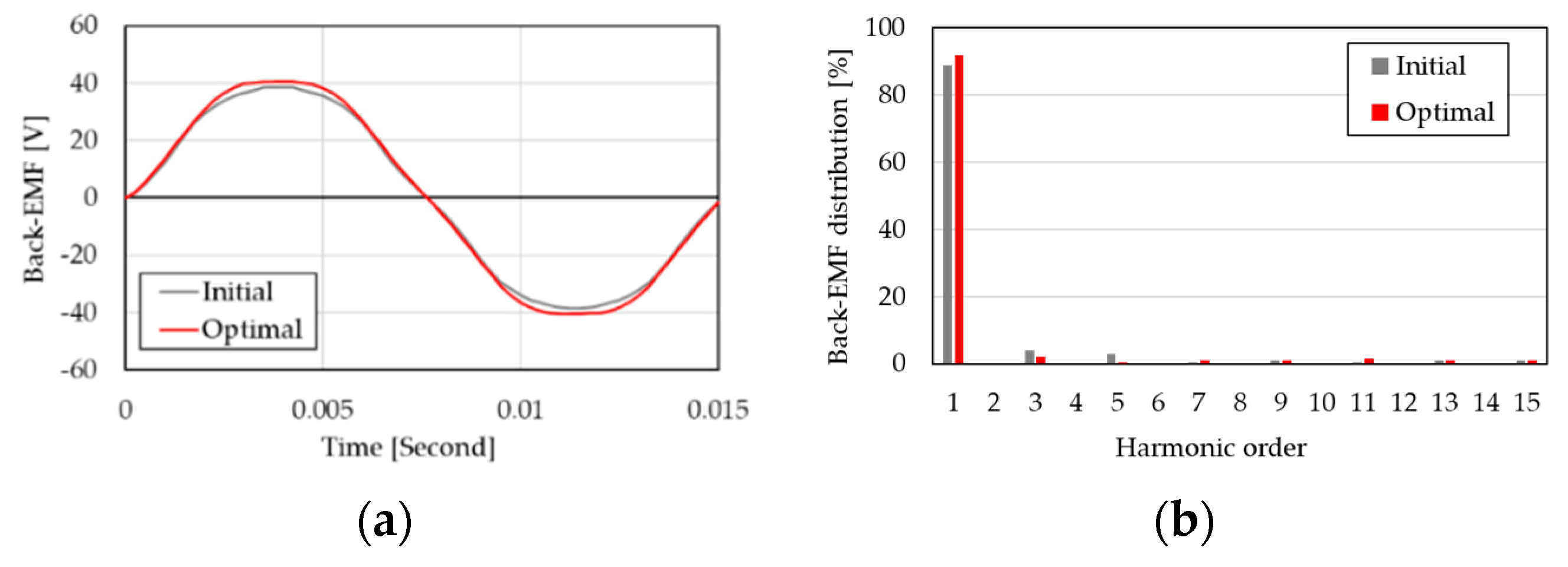
Figure 10a shows the line voltage of back-EMF at 1000 rpm at no-load conditions. The back-EMF waveform is a major factor that affects the torque characteristics. As the shape of the back-EMF waveform resembles the sinusoidal wave with lesser distortion, a smaller torque ripple response is generated. The maximum value of the no-load back-EMF with harmonics is 38.557 V for the initial model and 40.566 V for the optimal model. At the maximum operating speed of the PMSM at 12,000 rpm, the maximum back-EMF is 486.792 V. It can be observed that it has a margin of 18.8% regarding the IGBT withstand voltage specification of 600 V used in this study. Figure 10b shows the distribution ratio of each harmonic order based on the total harmonic distortion (THD) analysis of the back-EMF waveform. When the fundamental component of the back-EMF waveform is increased, the efficiency is improved. It can be observed that the fundamental wave component of the optimal model is improved by 2% compared with the initial model.
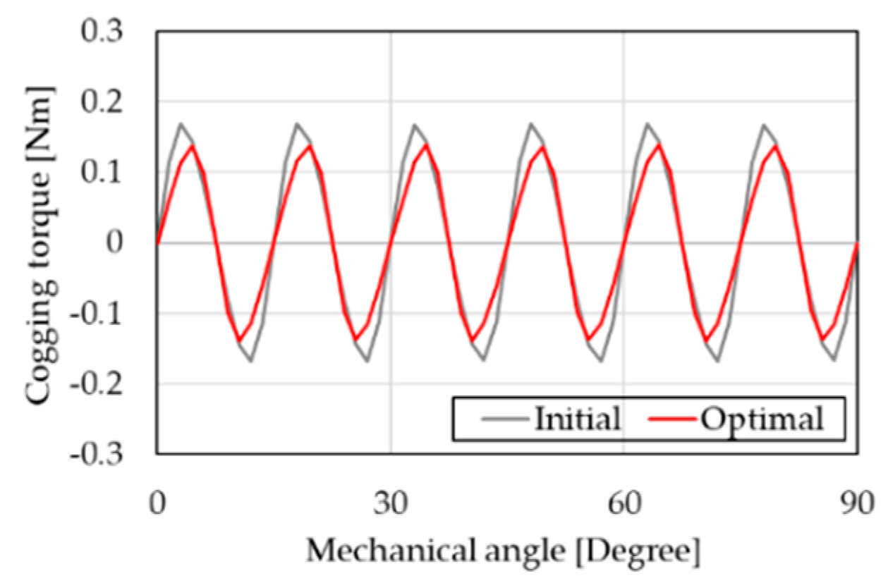
Figure 11 shows the comparison of the cogging torque characteristics of the initial and the optimal models. The optimum model’s cogging torque is 0.2778 Nm, which is smaller than the constraint of the initial model of 0.3479 Nm. Based on FE analyses, the cogging torque of the optimal model was reduced by 20.2% compared with the initial model.

4.1.2. Load Analysis

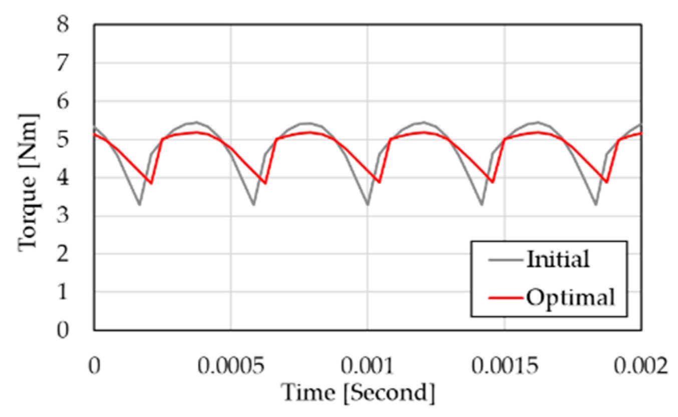
Owing to the characteristics of the compressor with constant torque characteristic load, the PMSM must maintain an increased efficiency at the rated operating conditions to achieve an efficiency improvement effect. The characteristics of the rated torque of the PMSM for electric compressors used for the cooling of the electric vehicles are compared in Figure 12. At this time, the rated power is 3 kW, and the rated speed is 6000 rpm. Additionally, the characteristics are applicable to the rated load of 4.775 Nm. The peak-to-peak value of torque ripple was calculated to be 2.16 Nm for the initial model, and 1.34 Nm for the optimal model. The torque ripple of the optimal model has improved by 38% compared with the initial model. Based on this analysis, the rated efficiency was 92.0% for the initial model, and 93.5% for the optimal model, thus improving the efficiency by approximately 1.5%.
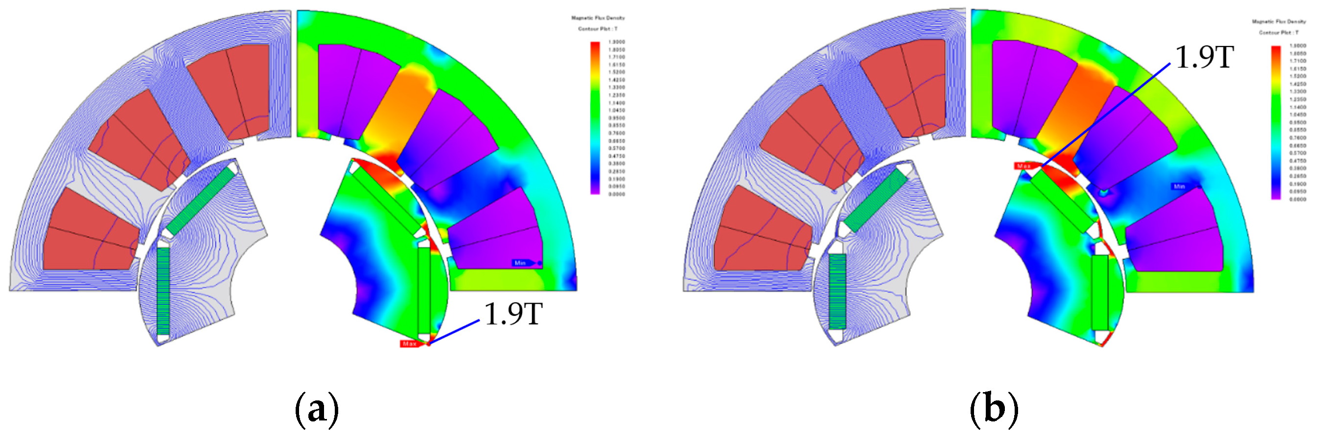
Figure 13 shows the flux distributions and magnetic flux densities of the initial and optimal models, respectively. The leakage flux that did not contribute to the output and magnetic saturation at the iron core was also analyzed. Based on the proposed rotor shape optimization process, an increased amount of magnetic flux flowed through the stator’s core in the case of the optimal model. In addition, improvements of magnetic flux flow and the effect of the variation of the magnetoresistance were obtained. These improved the back-EMF and reduced the cogging torque, as explained in the previous section. The maximum magnetic flux density of the rotor was 1.9 T for both the initial and the optimal models. This density was not saturated. Correspondingly, it was therefore considered that it was properly designed.

4.2. Experimental Results

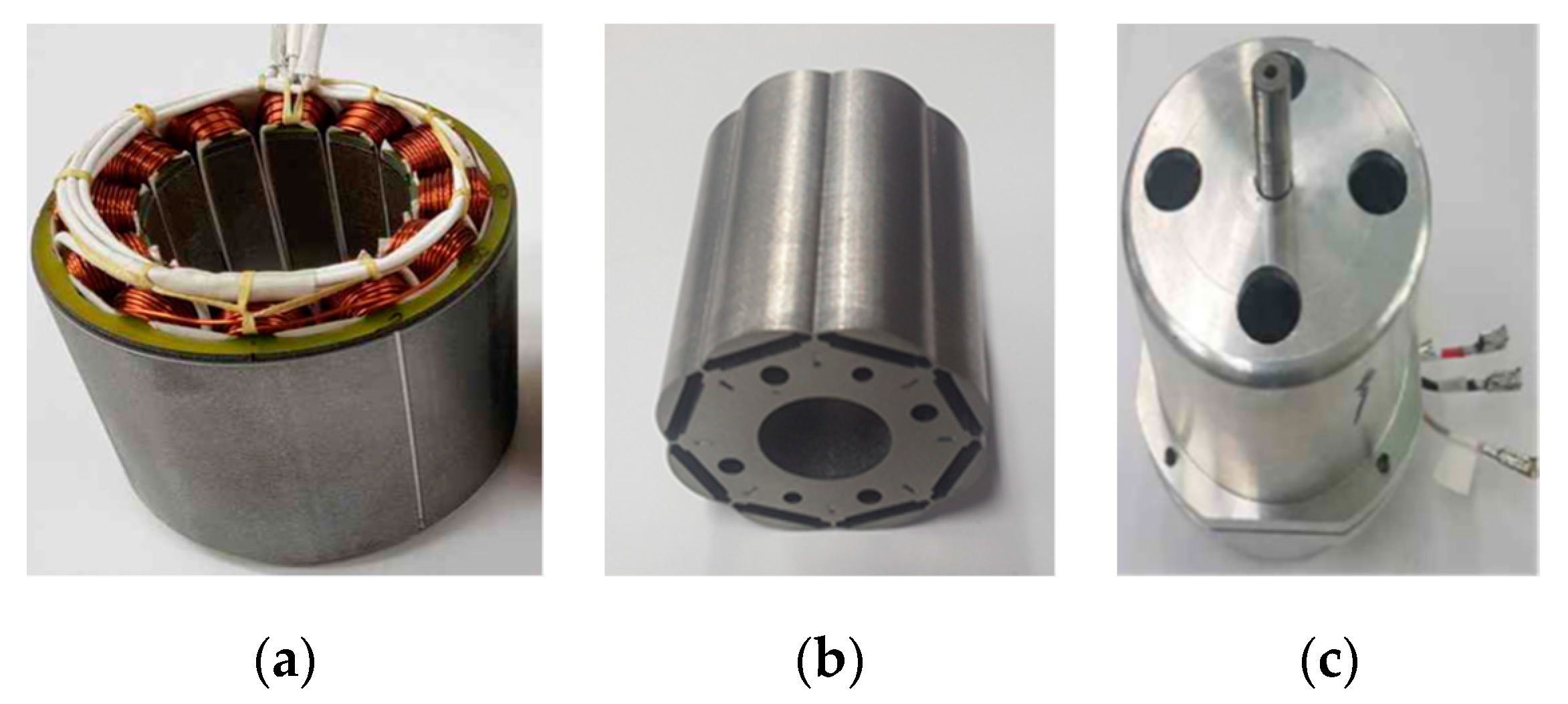
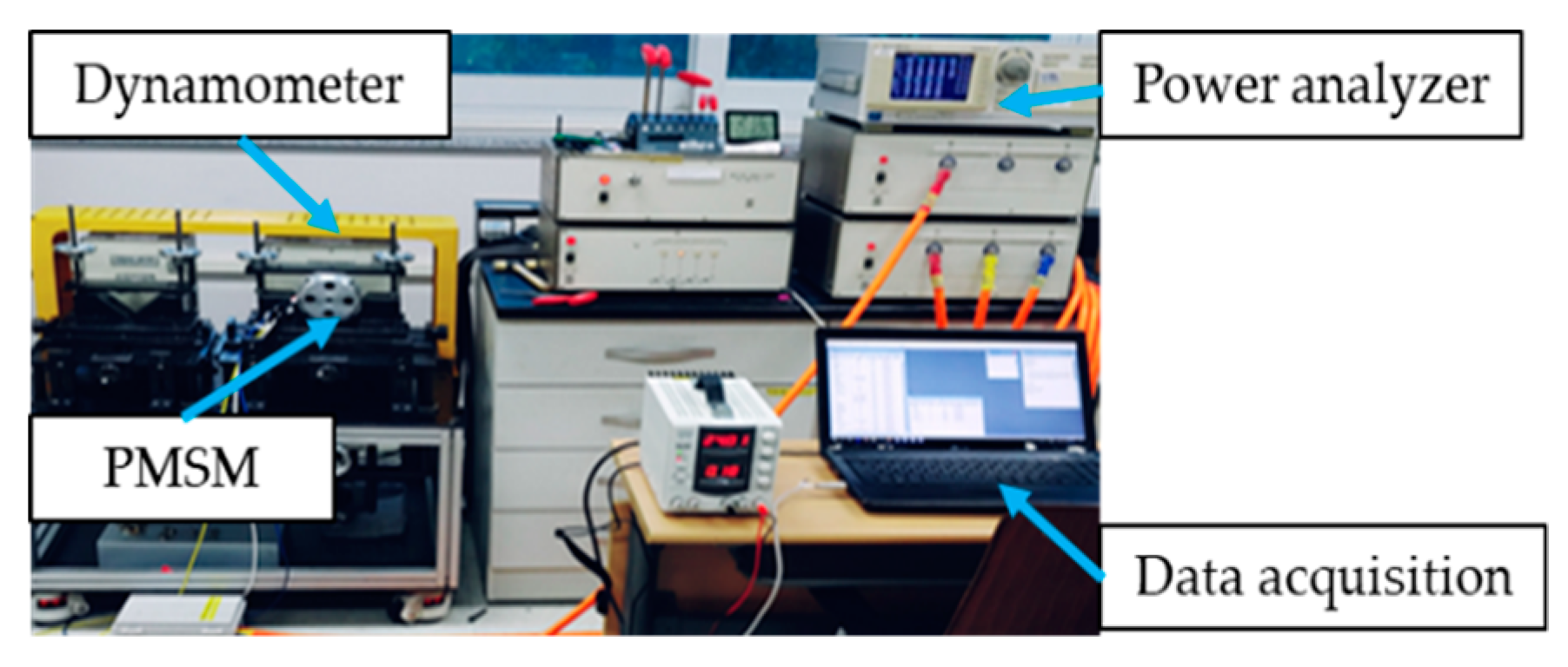
To verify the proposed optimal design process, a prototype of the optimal PMSM was fabricated. The prototype PMSM motor assembly, stator, and rotor, are shown in Figure 14, and the experimental setup is illustrated in Figure 15.
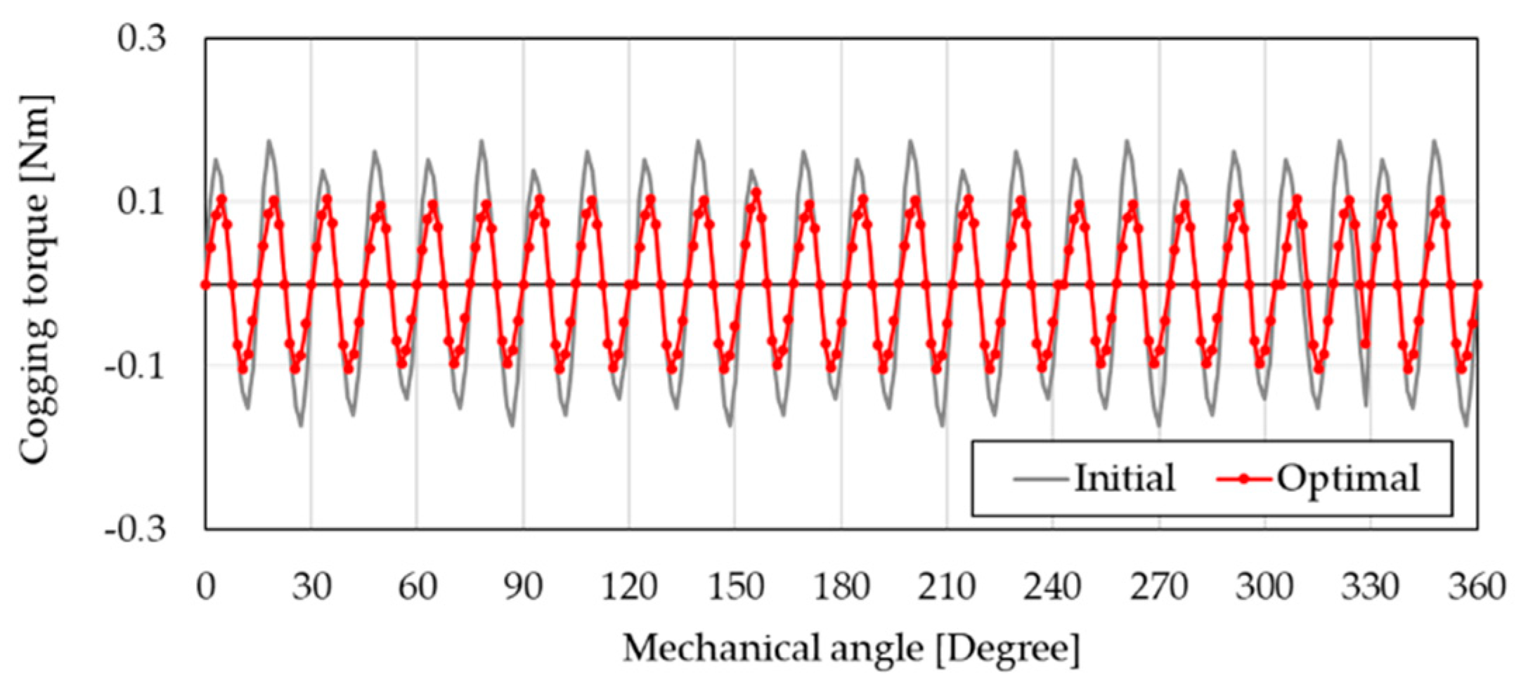
The results of the cogging torque experiment are compared and shown in Figure 16. The optimum model yielded a cogging torque of 0.2153 Nm which is reduced by 37.1% compared to 0.3369 Nm generated in the initial model. It is expected that the cogging torque characteristics have been improved based on rotor shape optimization. The results of the cogging torque experiment are compared and shown in Figure 16. The optimum model yielded a cogging torque of 0.2153 Nm, which was reduced by 39.2% compared to 0.3369 Nm of the initial model. It is expected that the cogging torque characteristics have been improved based on rotor shape optimization. However, there are several reasons for the existence of pulsation in the cogging torque waveform that are attributed to the harmonic component of the pole number. It is known that the number of pole harmonics is mainly caused by the shape error of the stator generated during manufacturing. This is also a factor that adversely affects the cogging torque that cannot be easily considered at the design stage. Thus, its complementary method needs to be studied further.
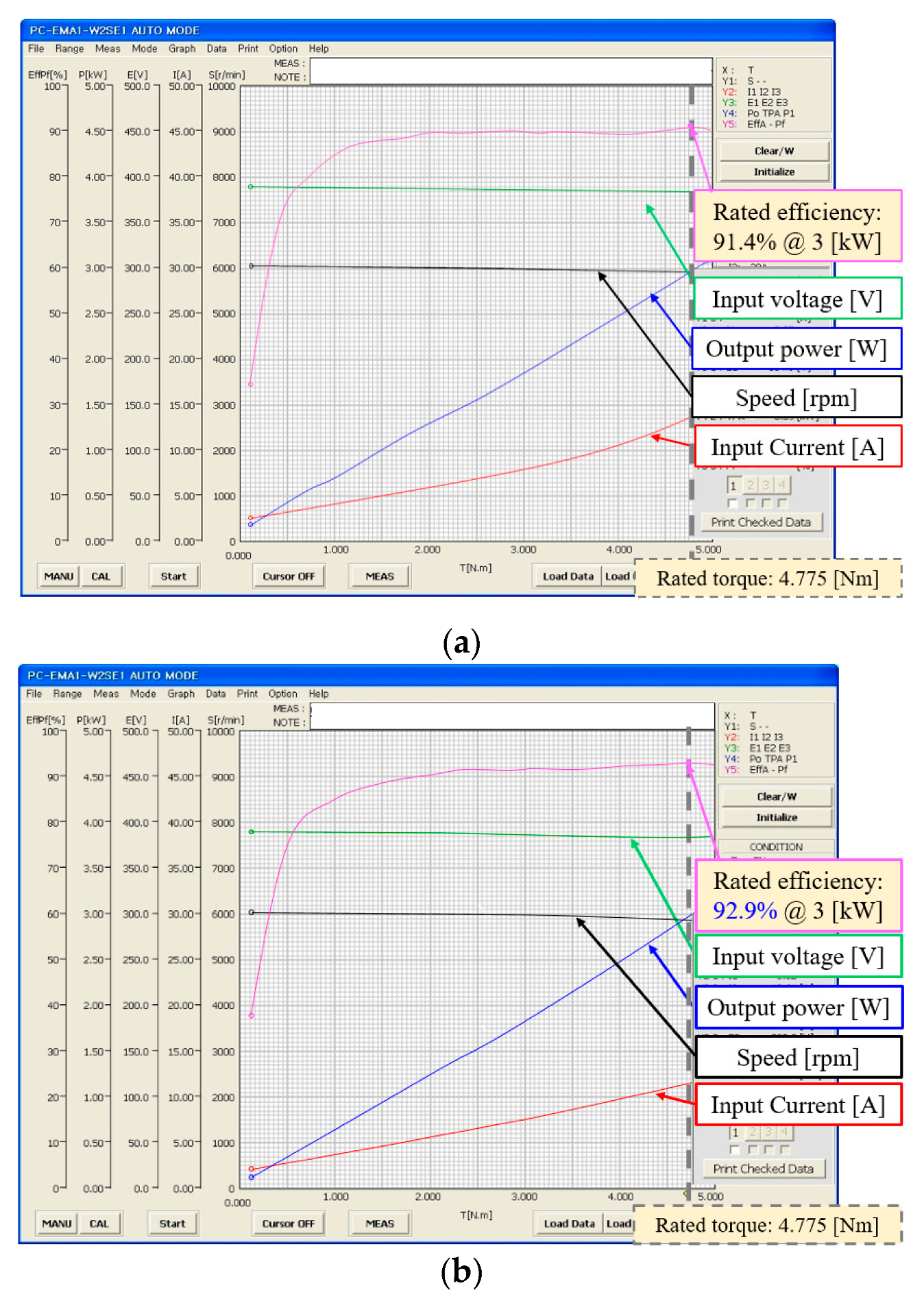
The experimental results of motor dynamo testing for the initial and optimal models are presented in Figure 17. The measurement targets include the rated efficiency in response to the rated load. The input direct current voltage was 380 V. To compare the operating characteristics, the PMSM motor was started and had an initial speed of 6000 rpm, while the load torque was continually increased until it reached the rated load of 4.775 Nm during the experiment. The experimental results showed that the rated efficiency of the initial model was 91.4%, and that of the optimal model was 92.9%, at the rated operating conditions (rotational speed of 6000 rpm and output power of 3 kW). The rated efficiency test characteristics were also found to be approximately 1.5% lower than the analysis. This is expected to be attributed to the difference between the physical properties considered in the design, the analysis used for the same material, and the physical properties applied to the prototype, as well as the component tolerances of the magnetic materials generated during the manufacturing of the prototypes, assembly tolerances, and errors attributed to test equipment settings. Table 4 summarizes the simulation and experimental results from each model.

5. Conclusions

In this study, the optimization of the rotor shape of the PMSM used in electric compressors was conducted. Accordingly, the rated efficiency and cogging torque characteristics of the rated output 3 kW PMSM were optimized. The design variables consisted of 54 experimental points without overlapping points with OHLD within the range of the designated design variables. For the approximate modeling, three metamodels were implemented to analyze the predicted accuracy. Among them, Kriging yielded the best characteristics. Additionally, the GA was selected as the optimal design variable that satisfied the objective function and constraints. The suitability of the proposed rotor shape optimization was analyzed based on FE analyses based on the selected optimal design variables. For practical verification, a prototype of the optimal model of PMSM was produced, and experiments confirmed the improvements of the efficiency and cogging torque characteristics compared with those of the initial model. According to the proposed optimization that was verified experimentally, the rated efficiency characteristics were improved by 1.5% compared with the initial model, while the cogging torque was reduced to 22.5%. In the future, the driving efficiency of the motor is expected to be improved when the electric compressor system of the test vehicle will be implemented.

Author Contributions

Conceptualization, S.-W.B.; Methodology, S.-W.B.; Software, S.-W.B.; Validation, S.-W.B. and S.W.L.; Writing—original draft preparation, S.-W.B.; Writing—review and editing, S.W.L.; and S.-W.B.; Funding acquisition, S.-W.B. All authors have read and agreed to the published version of the manuscript.

Funding

This paper was supported by the National Research Foundation of Korea (NRF) Grant funded by the Korea government (MSIT) (no. 2017R1C1B5075525); This study is the result of a research carried out as a part of ‘‘Green Vehicle Component Cluster Project’’ supported by the Ministry of Trade, Industry and Energy (MOTIE) and Korea Institute for Advancement of Technology (KIAT) (P0000760).

Acknowledgments

The author express gratitude to Koh-A Jung Gong Co., Ltd. and PIDOTECH for their technical support.

Conflicts of Interest

The authors declare no conflict of interest.

Appendix A

Table A1. Characteristics of samples obtained from optimal Latin hypercube design (OLHD) using finite element (FE) analyses.
NumberX1X2X3X4X5Efficiency (%)Cogging Torque (Nm)
112.0002.00024.16722.99822.26791.870.2746
212.9562.30623.62523.00021.16691.910.2774
314.8332.33323.27824.27821.38992.350.2816
412.3522.25022.83323.09121.45892.980.2939
512.4002.52822.88923.38921.05693.210.2881
614.1112.15024.44422.88921.00092.880.3242
712.7851.94624.61123.95220.76692.380.3438
812.3802.72023.30023.70021.90091.550.2778
912.2222.91624.55624.27522.00092.350.3412
1013.8892.13924.16124.10922.83391.370.2751
1113.5582.11124.67024.66222.05693.060.2736
1213.2152.88923.44423.22222.27893.060.3176
1314.7331.89023.89123.84021.63491.420.2765
1412.1222.47223.77823.61122.38993.440.3272
1513.4822.41722.44423.66720.50093.580.3385
1614.9712.19423.94824.74921.43393.010.2761
1713.3472.44423.11124.55521.83391.110.2863
1814.9332.25022.61123.55520.94493.410.3026
1914.4442.66722.94522.72322.77792.740.2855
2013.6682.63922.72223.66721.70491.510.2969
2114.5562.16723.55622.83522.47991.850.3275
2212.6311.83324.83123.32222.50093.130.3438
2313.0552.61122.77824.83320.94792.960.2973
2414.7231.77822.71223.72220.83291.490.2989
2513.4442.83323.83224.59722.15091.080.2779
2613.0001.75022.60824.50021.61191.120.3045
2714.8552.32023.72123.41121.50193.270.2771
2812.3452.97223.88324.38120.72291.270.2774
2912.7841.87223.57523.94222.66793.410.2781
3014.2341.65224.73823.16620.66592.990.2741
3112.6112.05524.44522.45321.83592.560.2737
3214.2782.54024.38823.44422.61193.340.2738
3313.1111.84722.32523.21321.74891.030.3178
3413.3442.29824.00024.39020.88993.210.2965
3514.8342.55625.00024.88522.40792.970.2833
3613.6671.69124.05622.58420.55692.630.2755
3713.8792.69523.16724.11721.92793.380.2829
3814.0561.63924.66622.66222.21693.670.2734
3914.6672.64222.45922.44422.85792.530.3112
4013.2502.23523.08824.72222.71193.040.2836
4112.4892.05724.33122.83222.95892.830.2751
4213.3672.76222.50324.97821.22292.910.3053
4314.9992.92224.27822.33320.39092.360.2941
4414.1452.45222.27122.55321.33392.610.2911
4513.2651.72122.38924.94422.94292.940.2839
4612.2561.62223.37822.38522.11392.490.2781
4714.3252.99624.94422.27821.21892.330.2735
4813.6501.58323.05124.22020.33391.370.2847
4912.4442.38922.45522.72220.22292.710.9267
5013.7771.94422.22222.19220.38992.210.3221
5113.4582.80524.24622.11120.22192.190.3333
5212.7981.55822.06023.83320.16793.450.3445
5314.7952.68522.79422.05620.05692.150.2736
5413.0751.50022.00122.00120.00192.110.3511

References

  1. Yilmaz, M.; Krein, P.T. Review of battery charger topologies, charging power levels, and infrastructure for plug-in electric and hybrid vehicles. IEEE Trans. Power Electron. 2013, 28, 2151–2169. [Google Scholar] [CrossRef]
  2. Chukwu, U.C.; Mahajan, S.M. Real-time management of power systems with V2G facility for smart-grid applications. IEEE Trans. Sustain. Energy 2014, 5, 558–566. [Google Scholar] [CrossRef]
  3. Babin, A.; Rizoug, N.; Mesbahi, T.; Boscher, D.; Hamdoun, Z.; Larouci, C. Total cost of ownership improvement of commercial electric vehicles using battery sizing and intelligent charge method. IEEE Trans. Ind. Appl. 2018, 54, 1691–1700. [Google Scholar] [CrossRef]
  4. Loiselle-Lapointe, A.; Whittal, I.; Christenson, M. Electric Vehicles: Impacts of Mileage Accumulation and Fast Charging. World Electr. Veh. J. 2016, 8, 249–262. [Google Scholar] [CrossRef] [Green Version]
  5. De Almeida, A.T.; Ferreira, F.J.; Baoming, G. Beyond Induction Motors—Technology Trends to Move Up Efficiency. IEEE Trans. Ind. Appl. 2013, 50, 2103–2114. [Google Scholar] [CrossRef]
  6. Yang, Z.; Shang, F.; Brown, I.P.; Krishnamurthy, M. Comparative study of interior permanent magnet, induction, and switched reluctance motor drives for EV and HEV applications. IEEE Trans. Transp. Electrif. 2015, 1, 245–254. [Google Scholar] [CrossRef]
  7. Lu, C.; Ferrari, S.; Pellegrino, G. Two Design Procedures for PM Synchronous Machines for Electric Powertrains. IEEE Trans. Transp. Electrif. 2017, 4, 98–107. [Google Scholar] [CrossRef] [Green Version]
  8. Jung, T.-U. Development of Hybrid Electric Compressor Motor Drive System for Hybrid Electrical Vehicles. J. Power Electron. 2009, 9, 960–968. [Google Scholar]
  9. Jolly, L.; Jabbar, M.A.; Qinghua, L. Design optimization of permanent magnet motors using response surface methodology and genetic algorithms. IEEE Trans. Magn. 2005, 41, 3928–3930. [Google Scholar] [CrossRef]
  10. Hwang, C.-C.; Cho, Y.H. Effects of leakage flux on magnetic fields of interior permanent magnet synchronous motors. IEEE Trans. Magn. 2001, 37, 3021–3024. [Google Scholar] [CrossRef]
  11. Ilka, R.; Alinejad-Beromi, Y.; Yaghobi, H. Techno-economic Design Optimisation of an Interior Permanent-Magnet Synchronous Motor by the Multi-Objective Approach. IET Electr. Power Appl. 2018, 12, 972–978. [Google Scholar] [CrossRef]
  12. Hong, G.; Wei, T.; Ding, X. Multi-objective Optimal Design of Permanent Magnet Synchronous Motor for High Effciency and High Dynamic Performance. IEEE Access 2018, 6, 23568–23581. [Google Scholar] [CrossRef]
  13. Cho, S.; Jung, K.; Choi, J. Design Optimization of Interior Permanent Magnet Synchronous Motor for Electric Compressors of Air-Conditioning Systems Mounted on EVs and HEVs. IEEE Trans. Magn. 2018, 54, 1–5. [Google Scholar] [CrossRef]
  14. Baek, S. Optimum shape design of a BLDC motor for electric continuous variable valve timing system considering efficiency and torque characteristics. Microsyst. Technol. 2018, 24, 4441–4452. [Google Scholar] [CrossRef]
  15. Lee, S.; Baek, S. A study on the improvement of the cam phase control performance of an electric continuous variable valve timing system using a cycloid reducer and BLDC motor. Microsyst. Technol. 2020, 26, 59–70. [Google Scholar] [CrossRef]
  16. Ortega, A.J.P.; Paul, S.; Islam, R.; Xu, L. Analytical model for predicting effects of manufacturing variations on cogging torque in surface-mounted permanent magnet motors. IEEE Trans. Magn. 2016, 52, 3050–3061. [Google Scholar] [CrossRef]
  17. Zhou, Y.; Li, H.; Meng, G.; Zhou, S.; Cao, Q. Analytical calculation of magnetic field and cogging torque in surface-mounted permanent-magnet machines accounting for any eccentric rotor shape. IEEE Trans. Ind. Electron. 2015, 62, 3438–3447. [Google Scholar] [CrossRef]
  18. Lee, J.H.; Kim, J.W.; Song, J.Y.; Kim, Y.J.; Jung, S.Y. A Novel Memetic Algorithm Using Modified Particle Swarm Optimization and Mesh Adaptive Direct Search for PMSM Design. IEEE Trans. Magn. 2016, 52, 1–4. [Google Scholar] [CrossRef]
  19. Edhah, S.O.; Alsawalhi, J.Y.; Al-Durra, A.A. Multi-Objective Optimization Design of Fractional Slot Concentrated Winding Permanent Magnet Synchronous Machines. IEEE Access 2019, 7, 162874–162882. [Google Scholar] [CrossRef]
  20. Chung, S.U.; Kim, J.W.; Chun, Y.D.; Woo, B.C.; Hong, D.K. Fractional Slot Concentrated Winding PMSM with Consequent Pole Rotor for a Low-Speed Direct Drive Reduction of Rare Earth Permanent Magnet. IEEE Trans. Energy Convers. 2015, 30, 103–109. [Google Scholar] [CrossRef]
  21. Kwon, J.W.; Lee, J.H.; Zhao, W.L.; Kwon, B.I. Flux-Switching Permanent Magnet Machine with Phase-Group Concentrated-Coil Windings and Cogging Torque Reduction Technique. Energies 2018, 11, 2758. [Google Scholar] [CrossRef] [Green Version]
  22. Yoon, K.-Y.; Baek, S.-W. Robust design optimization with penalty function for electric oil pumps with BLDC motors. Energies 2019, 12, 153. [Google Scholar] [CrossRef] [Green Version]
  23. Guo, H.; He, H.; Sun, F. A combined cooperative braking model with a predictive control strategy in an electric vehicle. Energies 2013, 6, 6455–6475. [Google Scholar] [CrossRef]
  24. Ma, P.; Zhou, Y.; Shang, X.; Yang, M. Firing accuracy evaluation of electromagnetic railgun based on multicriteria optimal Latin hypercube design. IEEE Trans. Plasma Sci. 2017, 45, 1503–1511. [Google Scholar] [CrossRef]
  25. Shin, P.S.; Woo, S.H.; Koh, C.S. An optimal design of large scale permanent magnet pole shape using adaptive response surface method with Latin hypercube sampling strategy. IEEE Trans. Magn. 2009, 45, 1214–1217. [Google Scholar] [CrossRef]
  26. Zhang, B.S.; Song, B.W.; Mao, Z.Y.; Tian, W.L.; Li, B.Y.; Li, B. Novel parametric modeling method and optimal design for savonius wind turbines. Energies 2017, 10, 301. [Google Scholar] [CrossRef] [Green Version]
  27. Li, Y.K.; Song, B.W.; Mao, Z.Y.; Tian, W.L. Analysis and optimization of the electromagnetic performance of a novel stator modular ring drive thruster motor. Energies 2018, 11, 1598. [Google Scholar] [CrossRef] [Green Version]
  28. Gong, J.; Gillon, F.; Canh, J.T.; Xu, Y. Proposal of a Kriging output space mapping technique for electromagnetic design optimization. IEEE Trans. Magn. 2017, 53, 1–4. [Google Scholar] [CrossRef]
  29. Zhang, L.; Tian, F. Performance study of multilayer perceptrons in a low-cost electronic nose. IEEE Trans. Instrum. Meas. 2014, 36, 1670–1679. [Google Scholar] [CrossRef]
  30. Franzese, G.; Visintin, M. Probabilistic ensemble of deep Information networks. Entropy 2020, 22, 100. [Google Scholar] [CrossRef] [Green Version]
  31. Baek, S.; Kwon, B. Optimum design of a single-phase line-start PM motor considering efficiency, maximum torque, and starting torque. IEEE Trans. Magn. 2012, 48, 4850–4859. [Google Scholar] [CrossRef]
  32. Yan, C.; Zhu, J.; Shen, X.; Fan, J.; Mi, D.; Qian, Z. Ensemble of regression-type and interpolation-type metamodels. Energies 2020, 13, 654. [Google Scholar] [CrossRef] [Green Version]
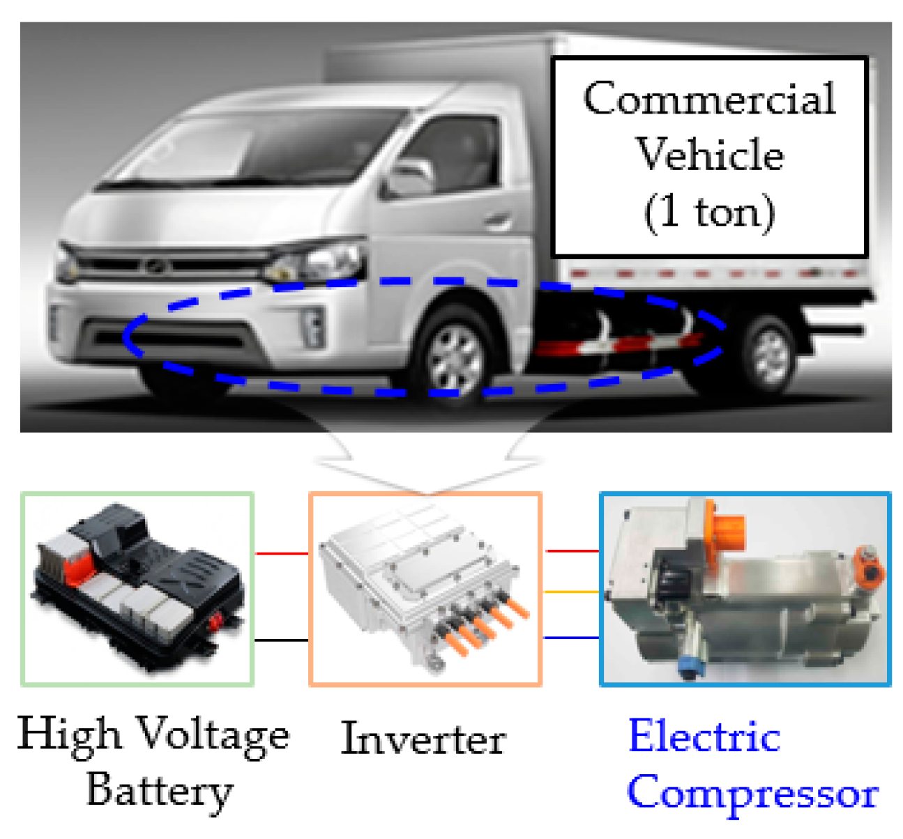
Figure 1. Cooling components of an electric vehicle.
Applsci 10 03235 g001
Figure 2. Shape of conventional permanent magnet synchronous motor (PMSM) for an electric compressor.
Applsci 10 03235 g002
Figure 3. Proposed optimization process.
Applsci 10 03235 g003
Figure 4. Rotor shape design variables.
Applsci 10 03235 g004
Figure 5. Sample distribution maps of optimal Latin hypercube design (OLHD): (a) X1; (b) X2; (c) X3; (d) X4; (e) X5.
Applsci 10 03235 g005
Figure 6. Conceptual diagram: (a) Kriging; (b) multilayer perceptron (MLP); (c) ensemble of decision tree (EDT).
Applsci 10 03235 g006
Figure 7. Root-mean-square error (RMSE) test results of metamodels for the objective function: (a) Efficiency; (b) Cogging torque.
Applsci 10 03235 g007
Figure 8. Convergence profiles of design variables: (a) X1; (b) X2; (c) X3; (d) X4; (e) X5.
Applsci 10 03235 g008
Figure 9. Comparison of initial and optimal models.
Applsci 10 03235 g009
Figure 10. Comparison of the back-electromotive force (EMF) characteristics between the initial and the optimal models at no-load conditions (rotation speed at 1000 revolutions per minute (rpm): (a) Waveform; (b) Harmonic.
Applsci 10 03235 g010
Figure 11. Comparison of the cogging torque characteristics.
Applsci 10 03235 g011
Figure 12. Comparison of the rated torque characteristics.
Applsci 10 03235 g012
Figure 13. Flux distribution and magnetic flux density: (a) Initial model; (b) optimal model.
Applsci 10 03235 g013
Figure 14. PMSM prototype for an electric compressor: (a) Stator; (b) rotor; (c) motor assembly.
Applsci 10 03235 g014
Figure 15. Experimental setup for motor dynamo testing.
Applsci 10 03235 g015
Figure 16. Comparison of the experimental cogging torque characteristics.
Applsci 10 03235 g016
Figure 17. Comparison of experimental motor dynamometer test results: (a) Initial model; (b) optimal model.
Applsci 10 03235 g017
Table 1. Specifications of the initial model of permanent magnet synchronous motor (PMSM) (rpm: revolutions per minute, EMF: electromotive force).
ItemsUnitValue
Required specificationInput voltageV380
Rated speedrpm6000
Rated output powerW3000
Operation frequencyHz400
Mechanical dimensionStator’s outer diametermm93
Stator’s inner diametermm51
Rotor’s outer diametermm50.2
Shaft diametermm20
Air gap lengthmm0.4
Stack lengthmm60
Electrical dimensionCoil turnsmm40
Coil thickness0.9
MaterialElectrical steel-35PN230
Permanent magnetN42UH
CharacteristicsBack-EMF(@1000rpm)Vrms27.8
Cogging torque(peak to peak)Nm0.3479
Torque(@rated speed)Nm4.775
Input current(@rated speed)Arms12.85
Efficiency(@rated speed)%91.40
Table 2. Ranges of the design variables
ParametersLower (XL)Upper (XU)UnitRemark
X11215mmMagnet length
X21.53.0mmMagnet width
X32225mmDistance between the center and the inner diameter of rotor
X42225mmDistance between the center and the magnet
X52023mmDistance between the center and the barrier
Table 3. Comparison of design variables.
ParametersInitialOptimalUnit
X114.312.4mm
X222.7mm
X323.823.3mm
X423.223.7mm
X521.321.9mm
Table 4. Simulation and experimental results.
ItemsInitialOptimalUnit
SimulationRated efficiency92.093.5%
Cogging torque0.34790.2778Nm
ExperimentRated efficiency91.492.9%
Cogging torque0.27780.2153Nm