Push-Out Tests on Various Steel Anchors with Partial-Length Welding in Steel–Concrete Composite Members


Abstract
:Featured Application
Abstract
1. Introduction
2. Test Program
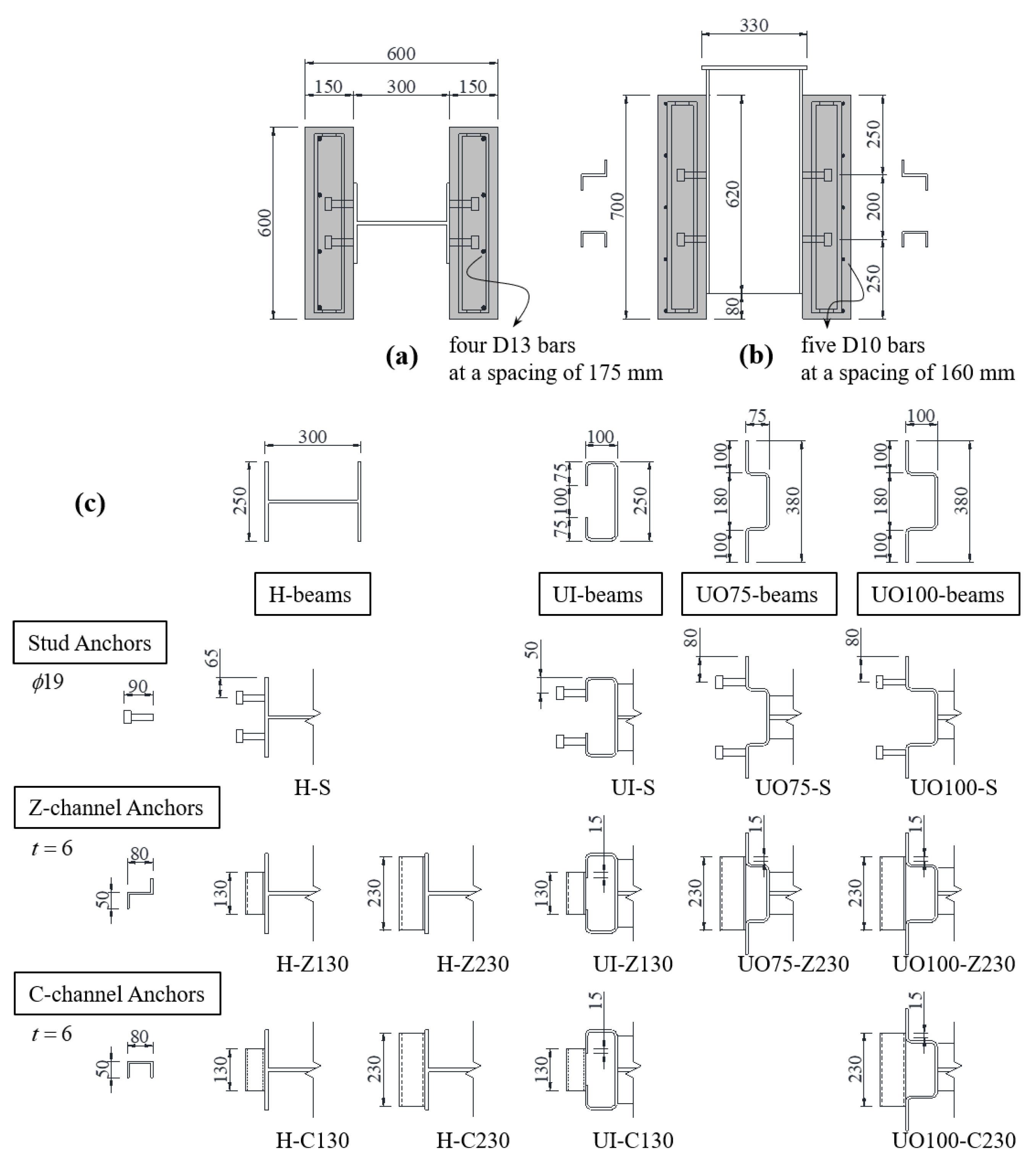
2.1. Test Specimens
2.2. Material Properties
2.3. Test Setup and Instrumentation
3. Test Results
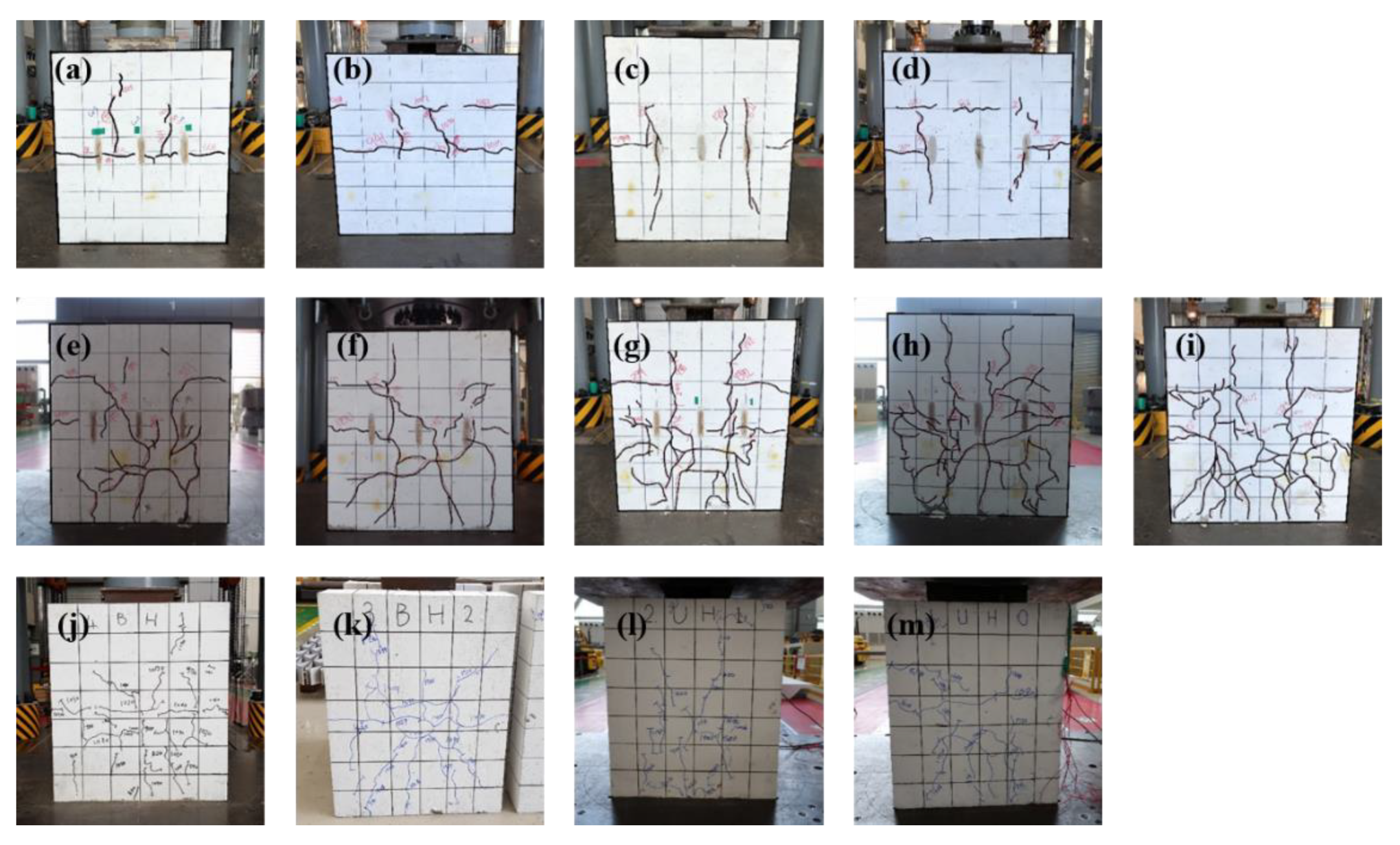
3.1. Failure Modes
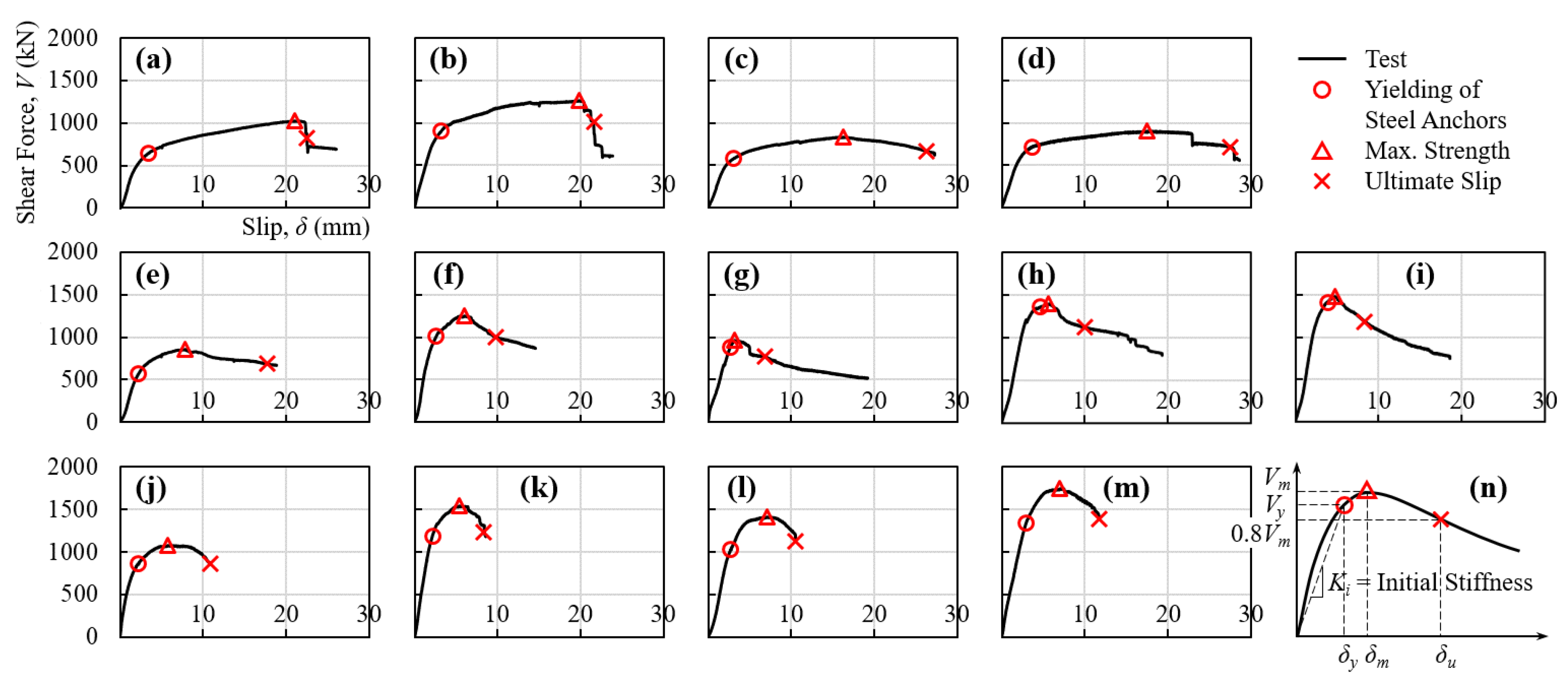
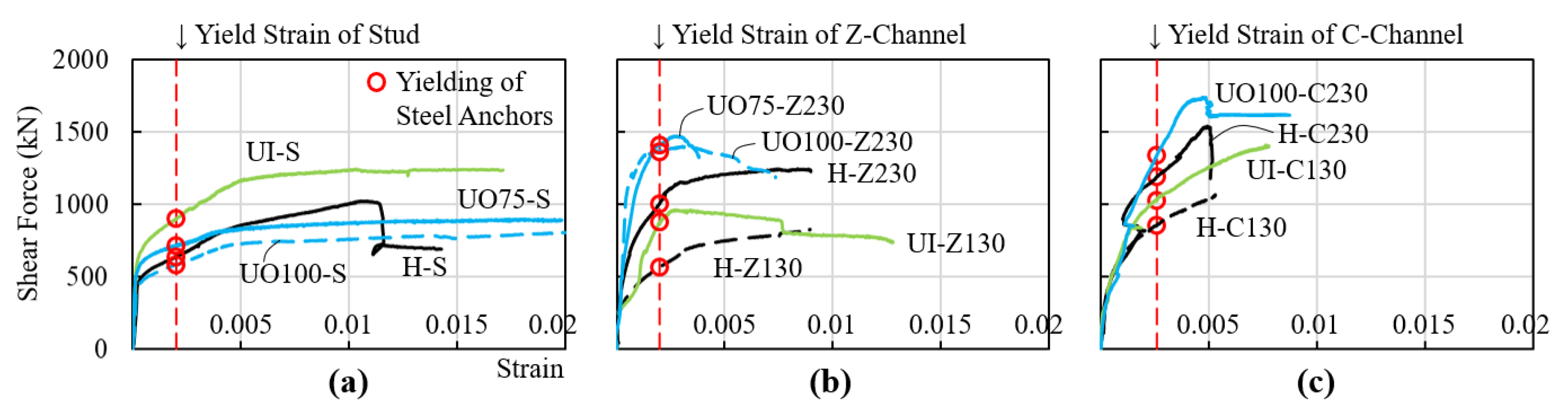
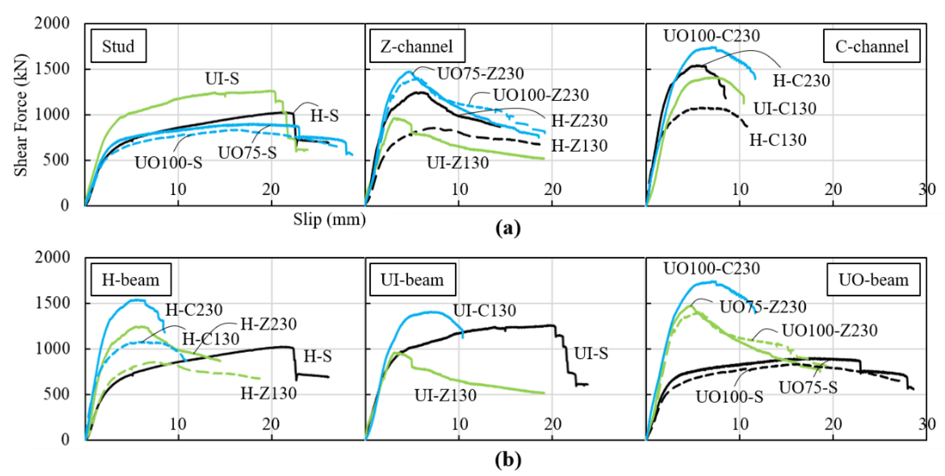
3.2. Shear Force—Slip Relationship
4. Discussions
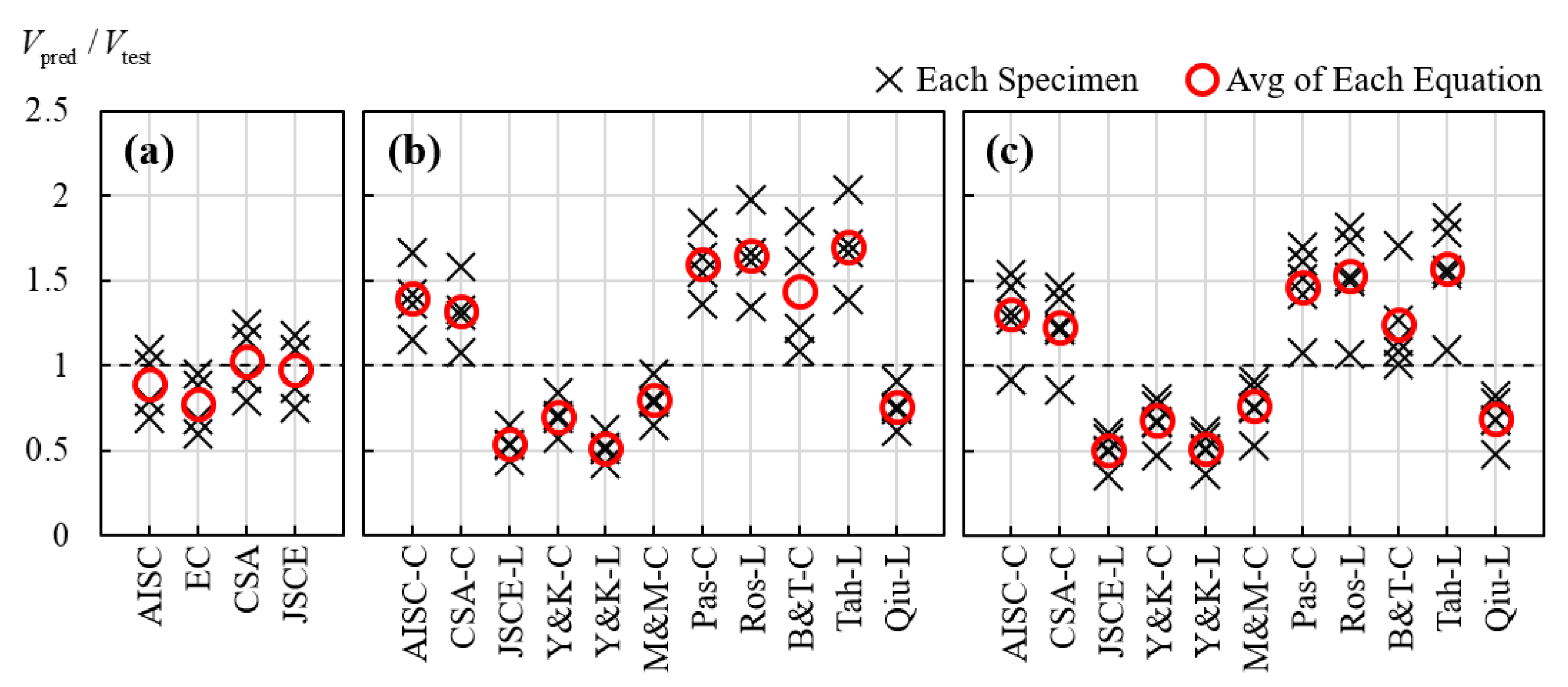
4.1. Existing Design Equations for Stud Anchors and Fully-Welded Channel Anchors
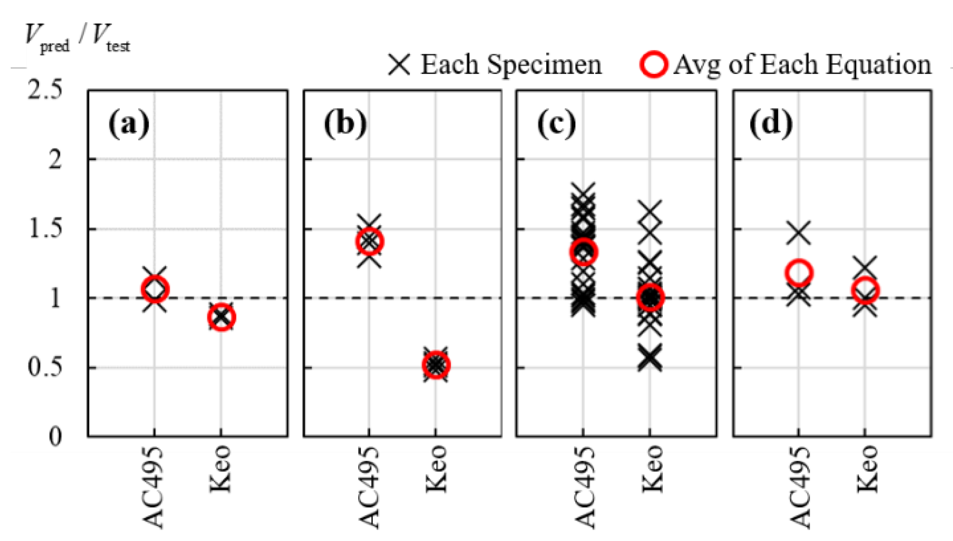
4.2. Comparison to Existing Design Equations for Channel Anchors with Partial-Length Welding
5. Conclusions
- (1)
- Although channel anchors with partial-length welding are widely used in current composite construction, the majority of current design codes and previous studies are for channel anchors with full-length welding.
- (2)
- Push-out test results showed that the performance of test specimens strongly depends on the types of steel anchors rather than the geometry of steel beams. The specimens with C-channel anchors showed highest load-carrying capacity but most drastic load reduction after the peak load. The specimens with Z-channel anchors showed a similar behavior to those with C-channel anchors, but the load reduction occurred in a slightly slower rate. The load-carrying capacity was increased with the length of Z- and C-channel anchors. The specimens with stud anchors reached the peak load in a slow rate and showed most ductile behavior.
- (3)
- Some of existing design equations for fully-welded channel anchors showed relatively good and conservative predictions after considering the contribution of the concrete inside the UH-beam cast monolithically with concrete slabs, but, fundamentally, it is not appropriate to apply the existing design equations for fully-welded channel anchors to the design of partially-welded channel anchors, because the failure mode and shear strength are strongly affected by the shape and welding condition of steel anchors.
- (4)
- Existing two design equations for partially-welded channel anchors were compared with the present and previous test results. The comparison showed that both equations are considered applicable to design, considering the fact that the design factors such as strength reduction factors and partial factors are used in actual design.
Author Contributions
Funding
Conflicts of Interest
Notations
| Aca1 | shear plane area 1 of channel anchor |
| Aca2 | shear plane area 2 of channel anchor |
| Acb | bearing area of channel anchor |
| Asa | cross-sectional area of stud anchor |
| bc | width of concrete measured at the interface between monolithically cast beam and slab |
| bca | width of channel anchor |
| dc | depth of concrete measured at the interface between monolithically cast beam and slab |
| dsa | shank diameter of stud anchor |
| dslab | depth of concrete slab |
| Ec | elastic modulus of concrete |
| fc’ | compressive strength of concrete |
| Fu | tensile strength of steel |
| Fy | yield strength of steel |
| hca | height of channel anchor |
| hsa | height of stud anchor |
| Ki | initial stiffness or secant stiffness at the point where steel anchors reach yield strain |
| Lbw | web-to-web clear distance of U-shaped cold-formed steel beam |
| Lca | length of channel anchor |
| Lca,w | welded length of channel anchor measured at one end |
| Qn | nominal shear strength of a steel anchor |
| sca | spacing of channel anchor |
| tf | flange thickness of channel anchor |
| tp | thickness of plate |
| tsc | lesser of thickness of channel anchor considering welded part and thickness of channel anchor itself |
| tw | web thickness of channel anchor |
| Vm | maximum shear strength or peak load |
| Vn | nominal shear strength of test specimen |
| Vnc | nominal shear strength of concrete inside UH-beam cast monolithically with concrete slab |
| δu | ultimate slip |
| δy | yield slip |
| μ | slip capacity or ratio of yield slip-to-ultimate slip |
| ρw | longitudinal reinforcement ratio |
Appendix A

| Authors | Specimen | Channel Anchor | Concrete Slab | Steel Beam |
|---|---|---|---|---|
| Keo et al. [4] | PO-L40 | Inv-L40 × 40 × 4 × 4, 550, 20 | 27.0, 200 | 288 |
| PO-L50a | Inv-L50 × 50 × 5 × 5, 445, 40 | 20.3, 200 | 288 | |
| PO-L50b | Inv-L50 × 50 × 5 × 5, 445, 40 | 21.3, 200 | 288 | |
| PO-L50c | Inv-L50 × 50 × 5 × 5, 445, 40 | 22.7, 200 | 288 | |
| Kim et al. [5] | EA-30–20–200 | Inv-L30 × 30 × 3 × 3, 421, 20 | 28.5, 150 | 388 |
| EA-30–30–200 | Inv-L30 × 30 × 3 × 3, 421, 30 | 28.5, 150 | 388 | |
| EA-30–40–200 | Inv-L30 × 30 × 3 × 3, 421, 40 | 28.5, 150 | 388 | |
| EA-30–20–300 | Inv-L30 × 30 × 3 × 3, 421, 20 | 28.5, 150 | 388 | |
| EA-30–30–300 | Inv-L30 × 30 × 3 × 3, 421, 30 | 28.5, 150 | 388 | |
| EA-30–40–300 | Inv-L30 × 30 × 3 × 3, 421, 40 | 28.5, 150 | 388 | |
| EA-40–20–200 | Inv-L40 × 40 × 5 × 5, 456, 20 | 28.5, 150 | 388 | |
| EA-40–30–200 | Inv-L40 × 40 × 5 × 5, 456, 30 | 28.5, 150 | 388 | |
| EA-40–40–200 | Inv-L40 × 40 × 5 × 5, 456, 40 | 28.5, 150 | 388 | |
| EA-40–20–300 | Inv-L40 × 40 × 5 × 5, 456, 20 | 28.5, 150 | 388 | |
| EA-40–30–300 | Inv-L40 × 40 × 5 × 5, 456, 30 | 28.5, 150 | 388 | |
| EA-40–40–300 | Inv-L40 × 40 × 5 × 5, 456, 40 | 28.5, 150 | 388 | |
| EA-50–20–200 | Inv-L50 × 50 × 6 × 6, 454, 20 | 28.5, 150 | 388 | |
| EA-50–30–200 | Inv-L50 × 50 × 6 × 6, 454, 30 | 28.5, 150 | 388 | |
| EA-50–40–200 | Inv-L50 × 50 × 6 × 6, 454, 40 | 28.5, 150 | 388 | |
| EA-50–20–300 | Inv-L50 × 50 × 6 × 6, 454, 20 | 28.5, 150 | 388 | |
| EA-50–30–300 | Inv-L50 × 50 × 6 × 6, 454, 30 | 28.5, 150 | 388 | |
| EA-50–40–300 | Inv-L50 × 50 × 6 × 6, 454, 40 | 28.5, 150 | 388 | |
| Lee et al. [6] | AN-160–60–4.5 | L60 × 40 × 4.5 × 4.5, 493, 80 | 29.2, 200 | 304 |
| AN-160–60–6 | L60 × 40 × 6 × 6, 478, 80 | 29.2, 200 | 304 | |
| AN-160–80–4.5 | L80 × 40 × 4.5 × 4.5, 493, 80 | 29.2, 200 | 304 | |
| AN-160–80–6 | L80 × 40 × 6 × 6, 478, 80 | 29.2, 200 | 304 |
References
- Johnson, R.P. Composite Structures of Steel and Concrete—Beams, Slabs, Columns, and Frames for Buildings, 3rd ed.; Blackwell Publishing: Oxford, UK, 2004; pp. 1–230. [Google Scholar]
- Kim, C.-S.; Park, H.-G.; Chung, K.-S.; Choi, I.-R. Eccentric Axial Load Testing for Concrete-Encased Steel Columns Using 800 MPa Steel and 100 MPa Concrete. J. Struct. Eng. 2012, 138, 1019–1031. [Google Scholar] [CrossRef]
- Baran, E.; Topkaya, C. An experimental study on channel type shear connectors. J. Constr. Steel Res. 2012, 74, 108–117. [Google Scholar] [CrossRef]
- Keo, P.; Lepourry, C.; Somja, H.; Palas, F. Behavior of a new shear connector for U-shaped steel-concrete hybrid beams. J. Constr. Steel Res. 2018, 145, 153–166. [Google Scholar] [CrossRef]
- Kim, Y.J.; Bae, J.H.; Ahn, T.S.; Jang, D.W. Push-out Test on Welded Angle Shear Connectors used in Composite Beams. J. Korean Soc. Steel Constr. 2014, 26, 155. [Google Scholar] [CrossRef] [Green Version]
- Lee, M.-K.; Shin, K.-J.; Lee, J.-S.; Chae, I.-S. Push-out Test on Evaluation of Shear Strength Using Angle Shear Connectors. J. Korean Soc. Steel Constr. 2019, 31, 413–421. [Google Scholar] [CrossRef]
- Viest, I.M.; Siess, C.P.; Appleton, J.H.; Newmark, N. Full-Scale Tests of Channel Shear Connectors and Composite T-beams; University of Illinois Bulletin: Urbana, IL, USA, 1952; Volume 50, pp. 1–155. [Google Scholar]
- Slutter, R.G.; Driscoll, G.C. Flexural strength of steel-concrete composite beams. J. Struct. Div. ASCE 1965, 91, 71–99. [Google Scholar]
- AISC. Specification for Structural Steel Buildings (ANSI/AISC 360-16); American Institute of Steel Construction: Chicago, IL, USA, 2016. [Google Scholar]
- Korea Construction Standards Center. Design Standards for Structural Steel Buildings (KDS 41 31 00); Korea Construction Standards Center: Goyang-si, Korea, 2019. [Google Scholar]
- CSA. Design of Steel Structures (CSA S16-09); Canadian Standards Association: Mississauga, ON, Canada, 2009. [Google Scholar]
- Yokota, H.; Kiyomiya, O. Load carrying capacity of shear connectors made of shaped steel in steel-concrete composite members. In Technical Note of The Port and Harbour Research Institute (No.595); Ministry of Transport: Tokyo, Japan, 1987. [Google Scholar]
- Maleki, S.; Mahoutian, M. Experimental and analytical study on channel shear connectors in fiber-reinforced concrete. J. Constr. Steel Res. 2009, 65, 1787–1793. [Google Scholar] [CrossRef]
- Pashan, A.; Hosain, M.U. New design equations for channel shear connectors in composite beams. Can. J. Civ. Eng. 2009, 36, 1435–1443. [Google Scholar] [CrossRef]
- Soty, R.; Shima, H. Formulation for Shear Force–Relative Displacement Relationship of L-Shape Shear Connector in Steel–Concrete Composite Structures. Ph.D. Thesis, Kochi University of Technology, Kochi, Japan, 2011. [Google Scholar]
- Tahmasbi, F.; Maleki, S.; Shariati, M.; Sulong, N.H.R.; Tahir, M.M. Shear Capacity of C-Shaped and L-Shaped Angle Shear Connectors. PLoS ONE 2016, 11, e0156989. [Google Scholar] [CrossRef] [PubMed] [Green Version]
- JSCE Committee on Hybrid Structures. Standard Specifications for Hybrid Structures (JSCE); Japan Society of Civil Engineers: Tokyo, Japan, 2014. [Google Scholar]
- Qiu, S.-Y.; Guo, Y.-T.; Nie, X.; Fan, J.-S.; Tao, M.-X. Experimental study on shaped steel shear connectors used in large-scale composite structures. J. Constr. Steel Res. 2020, 172, 106201. [Google Scholar] [CrossRef]
- CEN. Eurocode 4: Design of Composite Steel and Concrete Structures—Part 1.1: General Rules and Rules for Buildings (Eurocode 4-04); European Committee for Standardization: Brussels, Belgium, 2004. [Google Scholar]
- Korea Industrial Standards Commission. Steel Bars for Concrete Reinforcement (KS D 3504); Korea Industrial Standards: Seoul, Korea, 2019. [Google Scholar]
- Korea Industrial Standards Commission. Headed Studs (KS B 1062); Korea Industrial Standards: Seoul, Korea, 2014. [Google Scholar]
- Korea Industrial Standards Commission. Method of Tensile Test for Metallic Materials (KS B 0802); Korea Industrial Standards: Seoul, Korea, 2018. [Google Scholar]
- Korea Industrial Standards Commission. Standard Test Method for Compressive Strength of Concrete (KS F 2405); Korea Industrial Standards: Seoul, Korea, 2017. [Google Scholar]
- Park, R. Evaluation of ductility of structures and structural assemblages from laboratory testing. Bull. N. Z. Natl. Soc. Earthq. Eng. 1989, 22, 155–166. [Google Scholar] [CrossRef]
- ACI Committee 318. Building Code Requirements for Structural Concrete and Commentary (ACI 318-19); American Concrete Institute: Farmington Hills, MI, USA, 2019. [Google Scholar]
- Kuchma, D.A.; Wei, S.; Sanders, D.H.; Belarbi, A.; Novak, L.C. The development of the one-way shear design provisions of ACI 318-19. ACI Struct. J. 2019, 116, 285–295. [Google Scholar]
- ICC-ES. AC495—Cold-Formed Steel Structural Beams with Steel Angle Anchors Acting Compositely with Cast-in-Place Concrete Slabs; ICC Evaluation Service, LLC.: Brea, CA, USA, 2018. [Google Scholar]


| Group | Specimen 1 | Steel Beam 2 | Steel Anchors 2 (Length) | Concrete Slabs |
|---|---|---|---|---|
| S | HS | H—300 × 250 × 10 × 10 mm | S—ϕ19 × 90 mm | 150 × 600 mm |
| UI-S | UI—100 × 250 ×8 × 75 mm | S—ϕ19 × 90 mm | ||
| UO75-S | UO—75 × 180 × 8 × 100 mm | S—ϕ19 × 90 mm | ||
| UO100-S | UO—100 × 180 × 8 × 100 mm | S—ϕ19 × 90 mm | ||
| Z | H-Z130 | H—300 × 250 × 10 × 10 mm | Z—80 × 50 × 6 × 6 mm (130 mm) | |
| H-Z230 | H—300 × 250 × 10 × 10 mm | Z—80 × 50 × 6 × 6 mm (130 mm) | ||
| UI-Z130 | UI—100 × 250 × 8 × 75 mm | Z—80 × 50 × 6 × 6 mm (130 mm) | ||
| UO75-Z230 | UO—75 × 180 × 8 × 100 mm | Z—80 × 50 × 6 × 6 mm (130 mm) | ||
| UO100-Z230 | UO—100 × 180 × 8 × 100 mm | Z—80 × 50 × 6 × 6 mm (130 mm) | ||
| C | H-C130 | H—300 × 250 × 10 × 10 mm | C—80 × 50 × 6 × 6 mm (130 mm) | |
| H-C230 | H—300 × 250 × 10 × 10 mm | C—80 × 50 × 6 × 6 mm (130 mm) | ||
| UI-C130 | UI—100 × 250 × 8 × 75 mm | C—80 × 50 × 6 × 6 mm (130 mm) | ||
| UO100-C230 | UO—100 × 180 × 8 × 100 mm | C—80 × 50 × 6 × 6 mm (130 mm) |
| Structural Component | Material 1 | Thickness (mm) | Yield Strength (MPa) | Ultimate Strength (MPa) | Elongation (%) | Remarks |
|---|---|---|---|---|---|---|
| Steel Beam | SM355-10T (H-beam and web of UH-beam) | 10.1 | 404.7 | 551.9 | 23.6 | No. 1–9 |
| 10.0 | 385.0 | 522.7 | 24.7 | No. 10–13 | ||
| SM355-8T (flange of UH-beam) | 8.1 | 446.3 | 541.5 | 23.0 | No. 1–9 | |
| 7.8 | 304.7 | 473.0 | 27.3 | No. 10–13 | ||
| Steel Anchors | HS1-ϕ19 (stud anchor) | 19.0 | 413.8 | 478.7 | 17.3 | |
| SM355-6T (Z-channel anchor) | 6.0 | 406.8 | 524.4 | 32.7 | ||
| SM355-6T (C-channel anchor) | 5.8 | 533.3 | 606.3 | 18.7 | ||
| Slab | C24 (Concrete) | = 28.0 MPa at the day of testing (No. 1–9) = 30.3 MPa at the day of testing (No. 10–13) | ||||
| Specimen | Yielding of Steel Anchors | Maximum Strength | Ultimate Slip | |||
|---|---|---|---|---|---|---|
| Vy (kN) | δy (mm) | Ki = Vy/δy (kN/mm) | Vm (kN) | δu (mm) | μ = δu/δy | |
| H-S | 640.0 | 3.4 | 190.9 | 1024.6 | 22.5 | 6.7 |
| UI-S | 901.5 | 3.2 | 284.2 | 1262.5 | 21.6 | 6.8 |
| UO75-S | 718.6 | 3.7 | 195.4 | 900.0 | 27.5 | 7.5 |
| UO100-S | 584.0 | 3.1 | 189.7 | 834.1 | 26.3 | 8.5 |
| H-Z130 | 566.3 | 2.2 | 260.3 | 861.2 | 17.8 | 8.2 |
| H-Z230 | 1008.3 | 2.6 | 389.9 | 1246.5 | 9.7 | 3.8 |
| UI-Z130 | 876.8 | 2.6 | 335.1 | 963.5 | 6.9 | 2.6 |
| UO75-Z230 | 1411.2 | 3.9 | 363.0 | 1473.3 | 8.4 | 2.1 |
| UO100-Z230 | 1362.7 | 4.6 | 297.9 | 1401.2 | 10.0 | 2.2 |
| H-C130 | 857.7 | 2.2 | 392.4 | 1077.0 | 10.9 | 5.0 |
| H-C230 | 1191.0 | 2.2 | 553.9 | 1541.8 | 8.4 | 3.9 |
| UI-C130 | 1025.3 | 2.7 | 384.0 | 1409.8 | 10.4 | 3.9 |
| UO100-C230 | 1340.5 | 2.9 | 456.2 | 1740.9 | 11.7 | 4.0 |
| Design Code or Authors | Design Equation, Qn [N] 1 |
|---|---|
| ANSI/AISC 360-16 [9] & KDS 41 31 00 [10] | for stud anchor where Rg = 1.0 and = 0.75 throughout the present study for C-channel anchor |
| CSA S16-09 [11] | for stud anchor for C-channel anchor |
| Eurocode 4-04 [19] | for stud anchor where |
| Yokota and Kiyomiya [12] | for C-channel anchor for L-channel anchor |
| Maleki and Mahoutian [13] | for C-channel anchor |
| Pashan and Hosain [14] | for C-channel anchor |
| Ros [15] | for L-channel anchor |
| Baran and Topkaya [3] | for C-channel anchor |
| Tahmasbi et al. [16] | for L-channel anchor |
| JSCE [17] | for stud anchor for L-channel anchor where , , |
| Qiu et al. [18] | for L-channel anchor where, |
| Authors | Specimen | Anchor Shape | Vtest | Vpred by Equation (3) | Vpred by Equation (4) |
|---|---|---|---|---|---|
| Present Study | UI-Z130 | Z | 963.5 | 1071.6 | 1178.3 |
| UO75-Z230 | Z | 1473.3 | 1117.6 | 1407.5 | |
| UO100-Z230 | Z | 1401.2 | 1117.6 | 1407.5 | |
| UI-C130 | C | 1409.8 | 1229.6 | 1250.2 | |
| UO100-C230 | C | 1740.9 | 1281.5 | 1493.4 | |
| Keo et al. [4] | PO-L40 | Inv-L | 637.1 | 604.6 | 516.3 |
| PO-L50a | Inv-L | 932.1 | 924.2 | 521.0 | |
| PO-L50b | Inv-L | 916.5 | 935.8 | 540.5 | |
| PO-L50c | Inv-L | 975.9 | 951.9 | 567.3 | |
| Kim et al. [5] | EA-30–20–200 | Inv-L | 404.0 | 447.4 | 463.7 |
| EA-30–30–200 | Inv-L | 488.0 | 583.5 | 463.7 | |
| EA-30–40–200 | Inv-L | 488.0 | 719.7 | 463.7 | |
| EA-30–20–300 | Inv-L | 324.0 | 335.5 | 347.7 | |
| EA-30–30–300 | Inv-L | 339.0 | 437.6 | 347.7 | |
| EA-30–40–300 | Inv-L | 390.0 | 539.8 | 347.7 | |
| EA-40–20–200 | Inv-L | 476.0 | 833.4 | 772.8 | |
| EA-40–30–200 | Inv-L | 720.0 | 1039.5 | 772.8 | |
| EA-40–40–200 | Inv-L | 744.0 | 1245.6 | 772.8 | |
| EA-40–20–300 | Inv-L | 393.0 | 625.1 | 579.6 | |
| EA-40–30–300 | Inv-L | 573.0 | 779.6 | 579.6 | |
| EA-40–40–300 | Inv-L | 567.0 | 934.2 | 579.6 | |
| EA-50–20–200 | Inv-L | 732.0 | 1053.1 | 927.3 | |
| EA-50–30–200 | Inv-L | 924.0 | 1265.1 | 927.3 | |
| EA-50–40–200 | Inv-L | 940.0 | 1477.1 | 927.3 | |
| EA-50–20–300 | Inv-L | 555.0 | 789.8 | 695.5 | |
| EA-50–30–300 | Inv-L | 693.0 | 948.8 | 695.5 | |
| EA-50–40–300 | Inv-L | 789.0 | 1107.8 | 695.5 | |
| Lee et al. [6] | AN-160–60–4.5 | L | 1561.6 | 2185.5 | 800.1 |
| AN-160–60–6 | L | 1877.5 | 2866.1 | 1066.8 | |
| AN-160–80–4.5 | L | 1670.6 | 2185.5 | 800.1 | |
| AN-160–80–6 | L | 1996.4 | 2866.1 | 1066.8 | |
| Accuracy of Prediction: m ± σ of Vpred/Vtest | 1.32 ± 0.23 | 0.94 ± 0.28 | |||
Publisher’s Note: MDPI stays neutral with regard to jurisdictional claims in published maps and institutional affiliations. |
© 2020 by the authors. Licensee MDPI, Basel, Switzerland. This article is an open access article distributed under the terms and conditions of the Creative Commons Attribution (CC BY) license (http://creativecommons.org/licenses/by/4.0/).
Share and Cite
Choi, I.-R.; Kim, C.-S. Push-Out Tests on Various Steel Anchors with Partial-Length Welding in Steel–Concrete Composite Members. Appl. Sci. 2021, 11, 105. https://doi.org/10.3390/app11010105
Choi I-R, Kim C-S. Push-Out Tests on Various Steel Anchors with Partial-Length Welding in Steel–Concrete Composite Members. Applied Sciences. 2021; 11(1):105. https://doi.org/10.3390/app11010105
Chicago/Turabian StyleChoi, In-Rak, and Chang-Soo Kim. 2021. "Push-Out Tests on Various Steel Anchors with Partial-Length Welding in Steel–Concrete Composite Members" Applied Sciences 11, no. 1: 105. https://doi.org/10.3390/app11010105