Article

Effect of Burner Operation on the Catalyst Tube Lifetime of a Steam Methane Reformer: A Numerical Study

Department of Aeronautical Engineering, National Formosa University, Huwei, Yunlin 632, Taiwan
Appl. Sci. 2021, 11(1), 231; https://doi.org/10.3390/app11010231
Submission received: 6 December 2020 / Revised: 24 December 2020 / Accepted: 25 December 2020 / Published: 29 December 2020
(This article belongs to the Special Issue Selected Papers from IMETI 2020)

Abstract

:
In this paper, the catalyst tube lifetime of a practical steam methane reformer is analyzed numerically. The effect of burner operating mode on the flow development, hydrogen yield, and catalyst tube lifetime is discussed, with the aim of improving the reformer performance. The results of this study reveal that using the periodic boundary conditions, the temperatures and hydrogen yields obtained are much lower than the experimental values and the pressures are much lower than those using the real model. This results in overestimating the catalyst tube lifetime and underestimating the reformer operation risk. The catalyst tubes in the downstream area have longer lifetimes, while those in the upstream area have shorter lifetimes. Turning the upstream burners off is more efficient to the catalyst tube lifetime, while turning off the central groups of burners is less efficient. The main drawback of turning off burners is the decrease of hydrogen yield.

1. Introduction

SMR (steam methane reforming) is frequently adopted for producing hydrogen in the petrochemical industry. The combustion reaction activated by the burners provides heat to the catalyst tubes in which the reforming reaction occurs, and the liquid petroleum gas or the natural gas is converted into hydrogen. For reformer design, a classical optimization task is the control of catalyst tube temperature because the catalysts inside the tube should have high activity while the tube should have minimal damage and acceptable lifetime.
In the past few decades, there has been a lot of research conducted on the analysis of the catalyst tube damage and lifetime. Leta et al. [1] analyzed the lifetimes of fired heater tubes. The authors statistically characterized the uncertainty associated with the omega creep procedure of the API-579 Part 10 by treating the primary input parameters as random variables and processes. They also employed Monte Carlo simulations to estimate the probability of tubes failing for a specified time. Tawancy [2] determined the cause of damage by investigating a reformer catalyst tube using diffraction, light microscopy, transmission electron microscopy, etc. Garbiak, Jasiński, and Piekarski [3] discussed the progress in increasing the catalyst tube lifetime and the reasons accounting for the withdrawal of catalyst tubes from service. Liu and Chen [4] addressed the microstructure evolutions and mechanical property variations of catalyst tubes after long-term service. The authors indicated that the content of the interdendritic carbide could be used to predict the tube lifetime. Ray et al. [5] used tensile testing, stress rupture testing, and microstructural analysis to predict the remnant life of a catalyst tube of eleven years of service. Alvino et al. [6] analyzed the damage characterization of two catalyst tubes of nearly 10 years of service. They employed scanning electron microscopy, light optical microscopy, and mechanical testing to inspect creep, aging, carburization, precipitation, cavitation, phase transformation, and incipient micro-cracking. The authors indicated that differences in process conditions, as well as type and frequency of cleaning maintenance for decoking, may lead to different damage mechanisms of degradation on catalyst tubes. Jaganathan Swaminathan et al. [7] analyzed the reformer catalyst tubes failed after eight years of service. They assessed the tube lifetime by Larson–Miller parameter method. The authors concluded that the failure was caused by the local overheat leading to premature creep failure. Maharaj, Imbert, and Dear [8] analyzed the remaining life for reformer tubes of a methanol plant. They evaluated the tube lifetimes from their outside diameters, inside diameters, and the middle of the tube thicknesses. Ray et al. [9] investigated the remaining life for the catalyst tubes of a fertilizer plant. The investigation included microscopy, hardness measurement, dimensional measurement, hot tensile tests, and accelerated creep tests. The authors concluded that overheating is the primary cause of the significant degradation in microstructures and mechanical properties of the catalyst tube. Gong, Tu, and Yoon [10] metallographically analyzed the damage states of a catalyst tube of ten years of service. They found that the catalyst tube is damaged more seriously in the lower portion. Le May, da Silveira, and Vianna [11] discussed the damage mechanisms of catalyst tubes and the assessment methods of damage extent and remaining life. They applied a simplified method to evaluate the damage extent. A radiographic procedure for evaluating creep damage is also described.
The rapid developments in computer technology, physical models, and numerical methods enable the broad application of CFD to analyze systems involving fluid flow and chemical reactions. Further, problems that cannot be investigated experimentally can also be analyzed using CFD. Some recent studies of SMR by CFD are reviewed below. Pashchenko [12] employed ANSYS Fluent to develop a CFD model for analyzing the SMR process in a real reformer. Their investigations were focused on determining the temperature and the species distributions in the reformer at different operating conditions. Pajak et al. [13] numerically studied the flow development in a SMR reactor. The reformer was divided into segments by the reactor. The authors claimed that their design made a significant improvement in the reformer temperature distribution. Chen et al. [14] applied CFD to investigate SMR for producing hydrogen in microchannel reactors. Some important design factors, including dimension, flow arrangement, heat/mass transfer, and catalyst, were examined. The authors quantitatively evaluated different transport phenomena and proposed several methods of improving the SMR process. Tran et al. [15] proposed a scheme that can generate the distribution of the outer surface temperature of a catalyst tube. The proposed scheme has two major steps: prediction and correction. Tran et al. [16] also introduced a procedure that can increase the reformer throughput by optimizing the reformer fuel input. In an earlier paper, Tran et al. [17] developed a scheme that can improve the reformer thermal efficiency. Tran et al. [18] also employed CFD approaches to analyze a practical steam methane reformer. They concluded that the CFD model could be applied to find out the risk of real reformer operation at unknown and possibly more favorable operating conditions. Lao et al. [19] numerically investigated the chemical reaction and transport phenomena in an industrial-scale catalyst tube. The authors chose the outer surface temperature of the tube as the manipulated input and the hydrogen yield as the controlled output to analyze the hydrogen production. Mokheimer et al. [20] numerically analyzed the effect of various operating parameters on the SMR process. They found that higher methane conversion could be obtained when the steam/methane molar ratio was increased. Further, the way how the ratio was changed also had a significant effect. Ni [21] developed a two-dimensional numerical model to investigate the reaction in a reformer. He pointed out that the SMR and WGS (Water Gas Shift) reaction rates reached their highest values at the inlet but decreased downstream.
In a previous study [22], a simplified model of a steam methane reformer was investigated numerically. The effect of the burners on/off combinations on the catalyst tube temperature and hydrogen yield was discussed. In this paper, we use CFD to analyze the chemical reaction and transport in a practical steam reformer. The temperatures and pressures of the catalyst tubes are inspected. This paper aims to investigate the influence of the burner operating mode on the catalyst tube lifetime and to seek a feasible way of improving the reformer performance.

2. Numerical Methodologies

2.1. Numerical Methods and Physical Models

In this research, we use ANSYS FLUENT V.17 [23] to analyze the flow development in a reformer. The governing equations are solved by the SIMPLE algorithm [24]. The convection terms are discretized by the second order upwind scheme, and the diffusion terms are discretized by the central difference scheme. Concerning the choice of physical models, FLUENT provides Spalart-Allmaras one-equation model, k-ε two-equation model, k-ω two-equation model, transition k-kl-ω three-equation model, transition SST four-equation model, Reynolds stress seven-equation model, scale-adaptive simulation (SAS), detached eddy simulation (DES), and large eddy simulation (LES) for simulation of turbulence. For simulation of radiation, FLUENT provides Rosseland radiation model, P-1 radiation model, discrete transfer radiation model (DTRM), surface-to-surface (S2S) radiation model, and discrete ordinates (DO) radiation model for choice. With respect to chemical reaction simulation, FLUENT provides species transport, non-premixed reaction, premixed reaction, partially premixed reaction, and composition PDF transport for choice. By referring to the SMR research by CFD mentioned in Section 1 and from the viewpoint of model accuracy, stability, and engineering application, turbulence is simulated by the standard k-ε model [25], radiation is simulated by the DO (discrete ordinate) radiation model [26], and chemical reaction is simulated by the FRED (finite rate/eddy dissipation) model [27]. The near-wall flow variables, including the velocity, temperature, and turbulence quantities, are solved by means of the standard wall functions [28]. The catalyst is modeled by the porous zone model, which is available in ANSYS FLUENT and has also been employed by Tran et al. [15,16,17,18,19] and Mokheimmer et al. [20] in their studies of steam methane reformer.
This research considers the 3D steady flow with chemical reaction. The governing equations include the continuity equation, momentum equation, turbulence model equation (k-ε model), energy equation, radiation model equation (DO radiation model), and chemical reaction model equation (FRED model). Among these models, only the FRED chemical reaction model is described below while the others and the convergence criterion have been stated in detail in one of the author’s previous studies [29].
The rth chemical reaction can be expressed as follows:
i = 1 N ν i , r μ i k f , r k b , r i = 1 N ν i , r μ i
where
  • N = number of chemical species in the system
  • ν i , r = stoichiometric coefficient for reactant i in reaction r
  • ν i , r = stoichiometric coefficient for product i in reaction r
  • μi = species i
  • k f , r = forward rate constant for reaction r
  • k b , r = backward rate constant for reaction r
Equation (1) applies for both reversible and non-reversible reactions. For non-reversible reactions, the backward rate constant, kb,r, in Equation (1) is simply omitted. The species transport equation for a chemical reaction system can be express as
· ( ρ v Y i ) = · ( ρ D i , m + μ t S c t ) Y i + R i + S i
where Yi, Di,m, Sct, Ri, and Si are the mass fraction, diffusion coefficient, turbulent Schmidt number, net generation rate, and extra source term of species i, respectively. The net source of chemical species i due to reaction is computed as the sum of the Arrhenius reaction sources over the NR reactions that the species participate in.
R i = M w , i r = 1 N R R ^ i . r
where Mw,i is the molecular weight of species i and R ^ i . r is the Arrhenius molar rate of creation/destruction of species i in reaction r. For a non-reversible reaction, the molar rate of creation/destruction of species i in reaction r is expressed as
R ^ i . r = Γ ( ν i , r ν i , r ) ( k f , r j = 1 N [ C j , r ] ( η j , r + η j , r ) )
For a reversible reaction,
R ^ i . r = Γ ( ν i , r ν i , r ) ( k f , r j = 1 N [ C j , r ] η j , r k b , r j = 1 N [ C j , r ] v j , r )
where
  • C j , r = molar concentration of species j in reaction r (kgmol/m3)
  • η j , r = rate exponent for reactant species j in reaction r
  • η j , r   = rate exponent for product species j in reaction r
  • Γ = net effect of third bodies on the reaction rate
The forward and backward rate constants for reaction r, kf,r and kb,r, are computed using the Arrhenius expression:
kf,r = ArTβre−Er/RT
k b , r = k f , r K r
where
  • Ar = pre-exponential factor (consistent units)
  • βr = temperature exponent (dimensionless)
  • Er = activation energy for the reaction (J/kgmol)
  • R = universal gas constant (J/kgmol-K)
  • Kr = the equilibrium constant for the rth reaction, is computed from
    K r = exp ( Δ S r 0 R Δ H r 0 R T ) ( p a t m R T ) i = 1 N ( ν i , r ν i , r )
    where patm denotes the atmospheric pressure (101,325 Pa). The term in the exponential function denotes the change in Gibbs free energy and its components are expressed as
    Δ S r 0 R = i = 1 N ( ν i , r ν i , r ) S i 0 R
    Δ H r 0 R T = i = 1 N ( ν i , r ν i , r ) h i 0 R T
    where S i 0 and h i 0 denote the standard-state entropy and standard-state enthalpy (heat of formation), respectively.
In the past few decades, there have been many kinetics data reported for the SMR reaction. Sugihara, Kawamura, and Iwai [30] reviewed eight of them with their individual application range of temperature. In this paper, the kinetics constants proposed by Ødegård, Johnsen, and Karoliussen [31] are adopted because their application range of temperature matches the operating temperature of the reformer investigated in this study.
In general, a reformer operates at high temperatures. For a non-premixed reaction, turbulence mixes the reactants and then advects the mixture to the reaction zone for quick reactions. For a premixed reaction, turbulence mixes the lower-temperature reactants and the higher-temperature products and then advects the mixture to the reaction zone for quick reactions. Therefore, the chemical reaction is generally mixing (diffusion) controlled. However, the flue gas, fuel gas, and air in a practical reformer are generally premixed before injecting into the reformer. Although the chemical reactions in most regions of a reformer are mixing controlled, in some regions, e.g., the neighborhood of the feed inlets, the chemical reactions are kinetically controlled. In existing chemical reaction models, the eddy dissipation model (EDM) [32] considers simultaneously the diffusion controlled and the kinetically controlled reaction rates. The net generation rate of species i in the rth chemical reaction is found from the smaller value of the following two reaction rates:
R i , r = ν i , r M w , i A ρ ε k min R ( Y R ν R , r M w , R )
R i , r = ν i , r M w , i A B ρ ε k P Y P j N ν j , r M w , j
where
  • Yp is the mass fraction of any product, P
  • YR is the mass fraction of a particular reactant, R
  • A is an empirical constant equal to 4.0
  • B is an empirical constant equal to 0.5
In general, the EDM works well for a non-premixed reaction. However, for a premixed reaction, the reaction may be activated immediately when the reactants are fed into a reformer. This is practically unrealistic. To overcome this unreasonable situation, ANSYS FLUENT provides another model, the Finite-Rate/Eddy-Dissipation (FRED) model, which combines the finite-rate model and the EDM. Using this model, the net generation rate of a species is taken as the smaller value of the Arrhenius reaction rate and the rate determined by EDM. The Arrhenius reaction rate plays the role of a switch that avoids the unreasonable situation of immediately activating reaction when the reactants are fed into a reformer. Once the reaction is activated, the eddy-dissipation rate is generally lower than the Arrhenius reaction rate, and the reaction rate is then determined by the EDM.

2.2. Numerical Setup

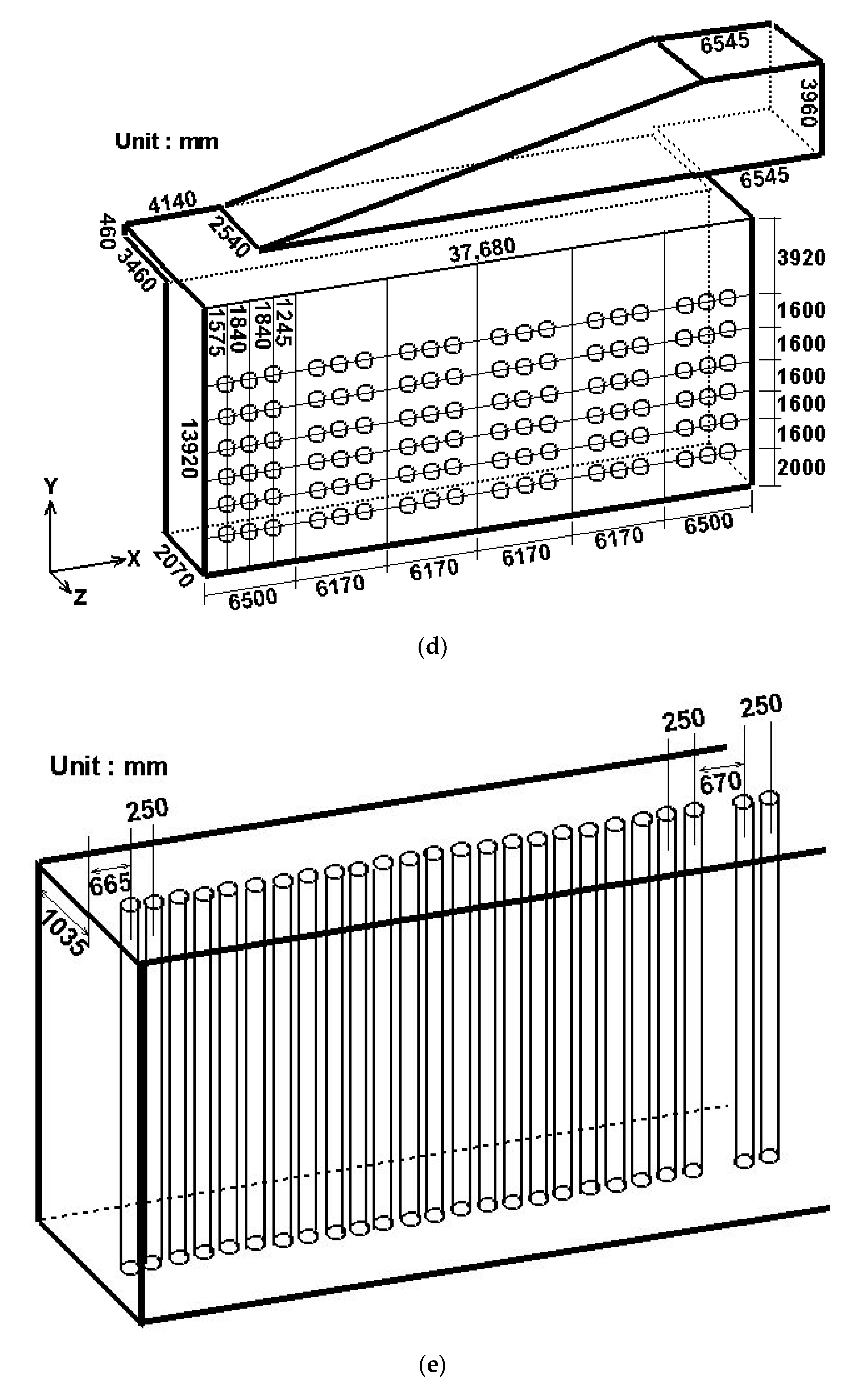
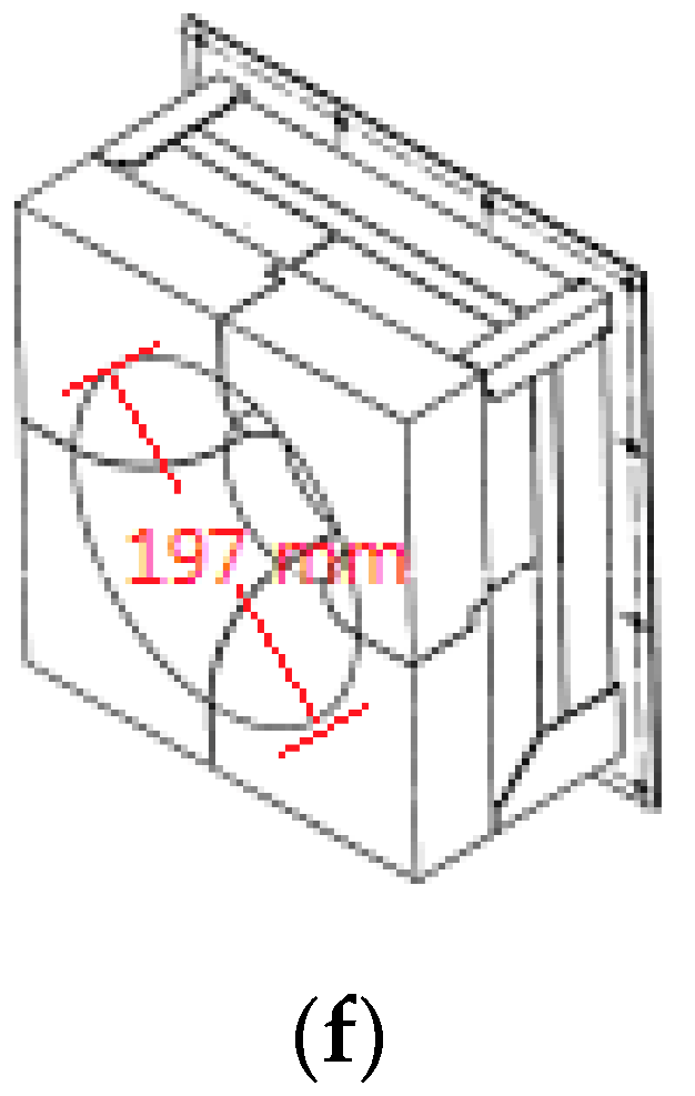
A practical reformer is simulated and compared with available experimental data to validate the employed numerical methods. Figure 1 shows the steam methane reformer investigated. Due to symmetry, merely half the reformer is simulated, as shown in Figure 1b. The reformer has a total of 276 catalyst tubes and 432 burners, i.e., each side of the reformer has 138 catalyst tubes and 216 burners. Each burner has a diameter 197 mm, as shown in Figure 1f. Each catalyst tube has an outside diameter 136 mm and a thickness 13.4 mm.
The real operating conditions used by a petrochemical corporation are adopted as the inlet conditions of burners and catalyst tubes. The boundary conditions for numerical simulation in this study are described below.
(1)
At the Symmetry planes, the symmetric boundary conditions are used.
(2)
At walls, standard wall function is applied.
(3)
At the burner inlets, i.e., fuel and flue gas inlets, the real operating conditions used by a petrochemical corporation are adopted, including
Q (Flowrate in the radial direction): 139,710 m3/hr
T (Temperature): 673.15 K
Pgauge (gauge Pressure): 1.04544 × 10⁴ N/m2
Species mole fraction, including
H2 (Hydrogen): 0.0816
CH4 (Methane): 0.0474
N2 (Nitrogen): 0.49057
O2 (Oxygen): 0.12818
CO2 (Carbon dioxide): 0.25225
(4)
At the burner exits, i.e., fuel and flue gas exits, the diffusion flux in the outflow direction is zero for all flow variables, and the conservation of mass should be satisfied.
(5)
At the inlets of the catalyst tubes, the real operating conditions used by a petrochemical corporation are adopted, including
Q (Flowrate in the axial direction): 24,740 m3/hr
T (Temperature): 912.75 K
Pgauge (gauge Pressure): 2.1658 × 10⁶ N/m2
Species mole fraction, including
CH4 (Methane): 0.2029
H2O (Steam): 0.6
H2 (Hydrogen): 0.12855
CO2 (Carbon dioxide): 0.06565
CO (Carbon Monoxide): 0.00145
N2 (Nitrogen): 0.00145
(6)
At the exits of the catalyst tubes, the diffusion flux in the outflow direction is zero for all flow variables, and the conservation of mass should be satisfied.
(7)
At the inlets of the burners or the catalyst tubes, the turbulence kinetic energy is assumed to be 10% of the inlet mean flow kinetic energy. The turbulence dissipation rate is calculated from:
ε = C μ 3 / 4 k 3 / 2 l
where l is connected with the hydraulic diameter, L, by l = 0.07 L.
From Figure 1b,d, we see that the catalyst tubes and burners can be divided into six groups. In an attempt to save the computational time, we also calculate and compare a simplified model which contains only one group of catalyst tubes and burners. Figure 1c shows the simplified model, which contains 23 catalyst tubes and 36 burners. The prototype differs from the simplified model in the left- and right-hand-side boundaries: the prototype has solid walls, while the simplified model has periodic boundaries. In case the simulation results using the simplified model are close to those using the prototype, the periodic model can be used instead of the prototype to save simulation time in view of engineering applications. On the other hand, if obvious difference exists between the simulation results using the prototype and the periodic model, the prototype should be adopted for subsequent simulation and discussion.
In this study, we use the software GAMBIT to generate grid mesh, which includes nearly four million cells for the prototype and one million cells for the periodic model, respectively. The computer used is a work station with Intel Core i7-8700 CPU and 64 GB ram. Number of cells used for the numerical simulation in this study has reached the limit of the above computer capacity. To ensure the adequacy of the grid mesh near the wall, the values of y* (the non-dimensionalized length between the wall and its interior neighboring node in the wall function method) are checked after the iteration process is converged. It is found that y* from the wall to its nearest interior neighboring node varies between 20.0 and 60.0, which lies in the logarithmic layer of the boundary layer. The grid mesh used in this paper is therefore adequate for using the wall function method.

3. Results and Discussions

3.1. Validation of the Numerical Methodologies

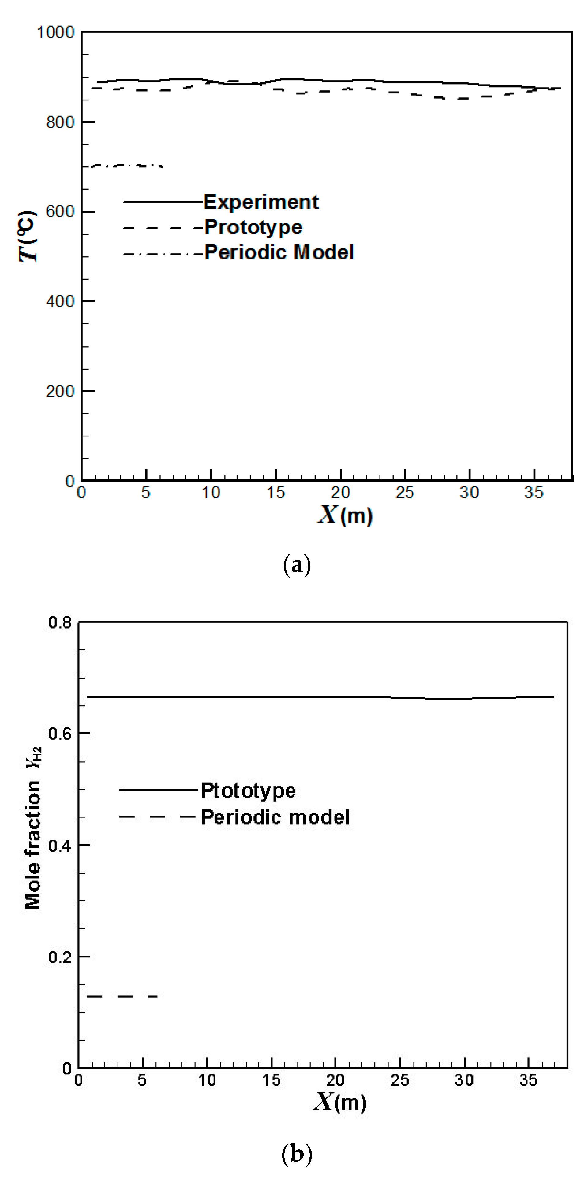
Firstly, we compare the simulation results with the available experimental data of a petroleum refinery. An Infrared thermographer is used to detect the temperature inside the reformer. Figure 2 compares the average temperatures at the outer surfaces and the hydrogen yields at the outlets of the catalyst tubes using the prototype and the periodic model. It can be seen that the results calculated from the real reformer agree better with the experimental data than that from the periodic model. The simulation error for the average temperatures at the outer surfaces of the catalyst tubes using the prototype is within 4%. On the other hand, the periodic model predicts much lower temperatures. Using the prototype, the predicted hydrogen yields are around 0.67 while the experimental hydrogen yields are around 0.69. The simulation error for the hydrogen yields at the catalyst tube outlets using the prototype is within 3%. On the other hand, the periodic model predicts very low hydrogen yields of around 0.13 due to its much lower predicted temperatures.
Table 1 compares the average temperatures at the front wall and the back wall of the reformer. It can be seen that the results using the prototype agree better with the experimental data while the periodic model yields much lower temperatures. This is because the prototype has the same boundaries as the real reformer while the periodic model has unconfined spaces for heat dissipation at the left- and right-hand-side boundaries, which leads to lower temperatures. The errors of the prototype simulation at the front wall and the back wall are 3.5% and 4.5%, respectively. On the other hand, the errors caused by the periodic model simulation are 22.9% for the front wall and 23.6% for the back wall, respectively.

3.2. Lifetime Estimate of the Prototype Reformer

In this study, the Larson–Miller parameter method [33] is applied to predict the catalyst tube lifetime. Catalyst tube failure may be attributed to many factors, e.g., manufacturing, casting, welding, local deformation, creep, etc. In the design phase of a catalyst tube under high temperature operation, the creep failure is usually of particular concern to engineers and metallurgists because most of the other factors are field effects and are not easy to evaluate in the design phase. Creep is severer for components operating under high temperatures or high stresses. With given operating conditions, Larson-Miller parameter method may be applied to estimate the corresponding lifetimes of the catalyst tubes. This would be helpful to find out an optimal operating condition for the catalyst tubes in high temperature operation. The Larson–Miller parameter is a correlation based on the Arrhenius rate equation. Its value is usually defined as follows.
LMP = T (C + log10 tr) × 10−3
where
  • T represents temperature (K),
  • tr represents stress-rupture time (hr),
  • C represents a constant, usually of the order 20.
After mathematical manipulation, Equation (14) can be rewritten as the following equation for the stress-rupture time.
tr = 10(1000 × LMP/TC)
For the catalyst tube material investigated in this paper, the correlation diagram of the Larson–Miller parameter is shown in Figure 3, and the constant C is 22.96, as suggested by the manufacturer [34].
The design operating conditions of the pressure and temperature for the catalyst tube investigated in this study are 24 kg/cm2 and 925 °C, respectively. The stress inside the catalyst tube can then be preliminarily estimated by the following equation to be 11.9 Mpa.
S = 0.5 P × Do/t
where
  • S represents the stress inside the catalyst tube,
  • Do represents the catalyst tube outside diameter,
  • t represents the catalyst tube thickness.
The design lifetime for the catalyst tube corresponding to the design operating conditions can then be calculated from Figure 3 and Equation (15) to be around 5 × 10⁶ h (or 570 year). Note that this lifetime is evaluated on the basis of design operating conditions which have taken a safety factor into account. Using the design operating conditions, the catalyst tube will have a very long lifetime. However, in practical operations, there are some operational, human and environmental factors, which will yield a shorter lifetime.
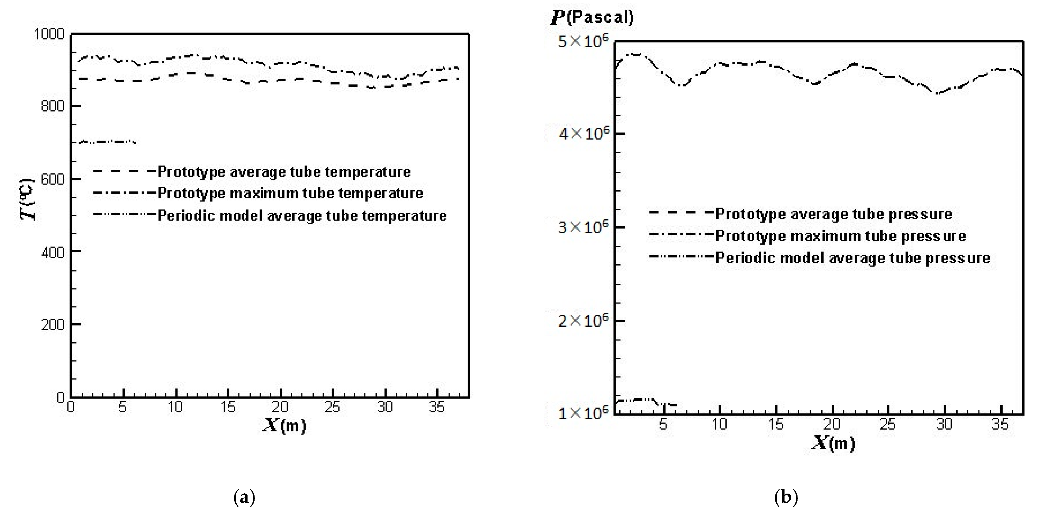
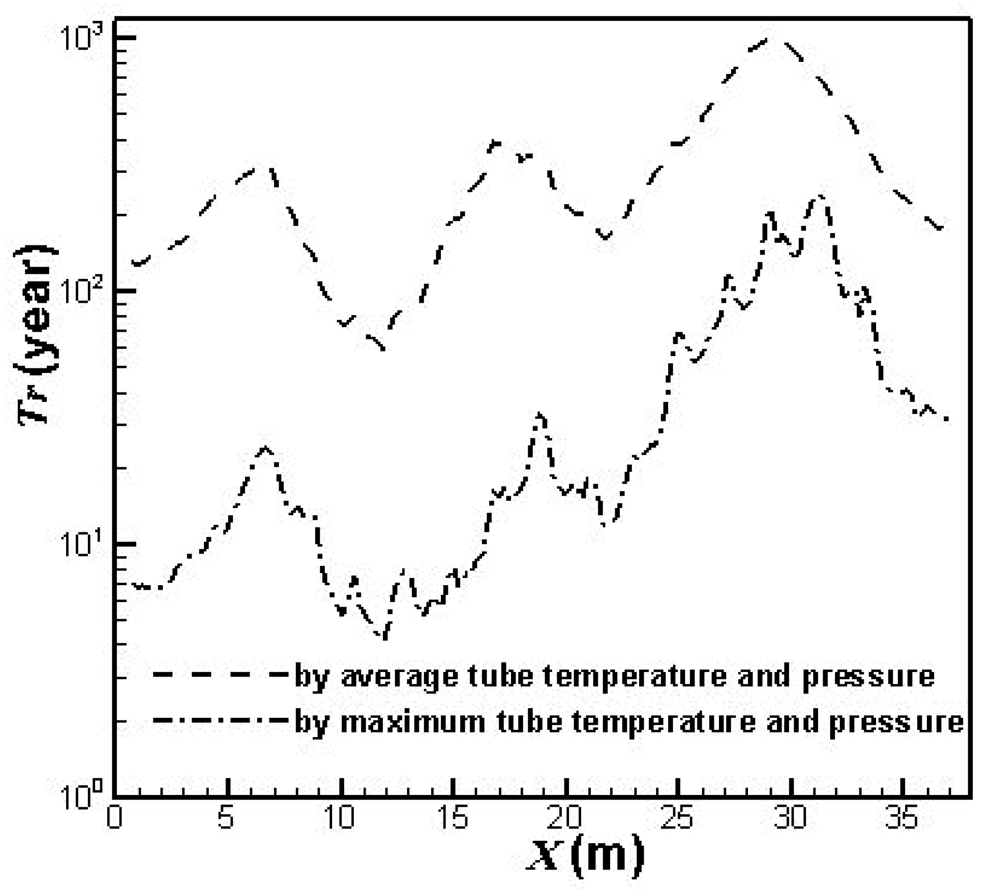
On the other hand, from the simulation results, the lifetimes for the catalyst tubes of the prototype reformer can be estimated from the calculated temperatures and pressures of the catalyst tubes shown in Figure 4. The results are shown in Figure 5.
Figure 4 shows the simulation results of the average and maximum outer surface temperatures as well as the average and maximum inner surface pressures of the catalyst tubes for the prototype reformer. The average outer surface temperatures and the average inner surface pressures of the catalyst tubes for the periodic model are also shown for comparison. It can be observed that the average and maximum inner surface pressures of the catalyst tubes for the prototype reformer nearly coincide. This is because the catalyst tube is filled with catalyst. The flow motion is very slow in the tube, and therefore the average and maximum inner surface pressures are nearly equal. From Figure 5, it is seen that the lifetime based on the average tube temperatures and pressures of the prototype reformer is approximately the same order of magnitude as the design lifetime. On the other hand, the lifetime based on the average tube temperatures and pressures of the periodic model (not shown in Figure 5) is approximately 1012 years, which is obviously unreasonable as compared to the design lifetime. It should be noted that the catalyst tubes can be ruptured in practical operation because the temperatures and pressures may exceed their average values. The lifetimes estimated from the maximum tube temperatures and pressures shown in Figure 5 reveal this fact. The catalyst tubes at the upstream areas can be ruptured at four years of service. It can also be observed from Figure 4 and Figure 5 that each catalyst tube has individual lifetime due to the different temperature and pressure in each catalyst tube. The catalyst tubes in the downstream areas have longer lifetimes because they are closer to the reformer exit where the divergent shape of the reformer top portion (roof) provides larger heat dissipation space. On the other hand, the catalyst tubes in the upstream areas have shorter lifetimes because they are farther from the reformer exit and hence the heat dissipation is worse.
From the above comparisons, it is found that obvious difference exists between the simulation results of the prototype and the periodic model. Therefore, the prototype is adopted for subsequent discussion.

3.3. Influence of the Burners Turned on or off

For the operation of a reformer, three basic requirements should be satisfied: safety, reliability and efficiency. When a steam reformer is operating, it is important to monitor the catalyst tube temperature because of the possible threats of thermal stress and creep damage. When the monitored temperature reaches a dangerous status, a prompt and feasible approach is to turn off some of the the burners. In this section, to explore the effect of the placement and numbers of burners turned on or off on the tube lifetime, the burners are divided into six groups, as shown in Figure 1d. The range of each group is as follows:
(1)
the first group: x = 0 ~ 6.5 m,
(2)
the second group: x = 6.5 ~ 12.67 m,
(3)
the third group: x = 12.67 ~ 18.84 m,
(4)
the fourth group: x = 18.84 ~ 25.01 m,
(5)
the fifth group: x = 25.01 ~ 31.18 m,
(6)
the sixth group: x = 31.18 ~ 37.68 m.
Each group contains 23 catalyst tubes and 36 burners. Further, each group can be controlled to be turned on or off. In the following discussion, we discuss twelve different burners on/off combinations, including fully opened, one group (group 1, 2, 3, 4, 5, or 6) turned off, two groups (group 1 & 2, 3 & 4, or 5 & 6) turned off, and three groups (group 1, 2 & 3 or 4, 5 & 6) turned off.
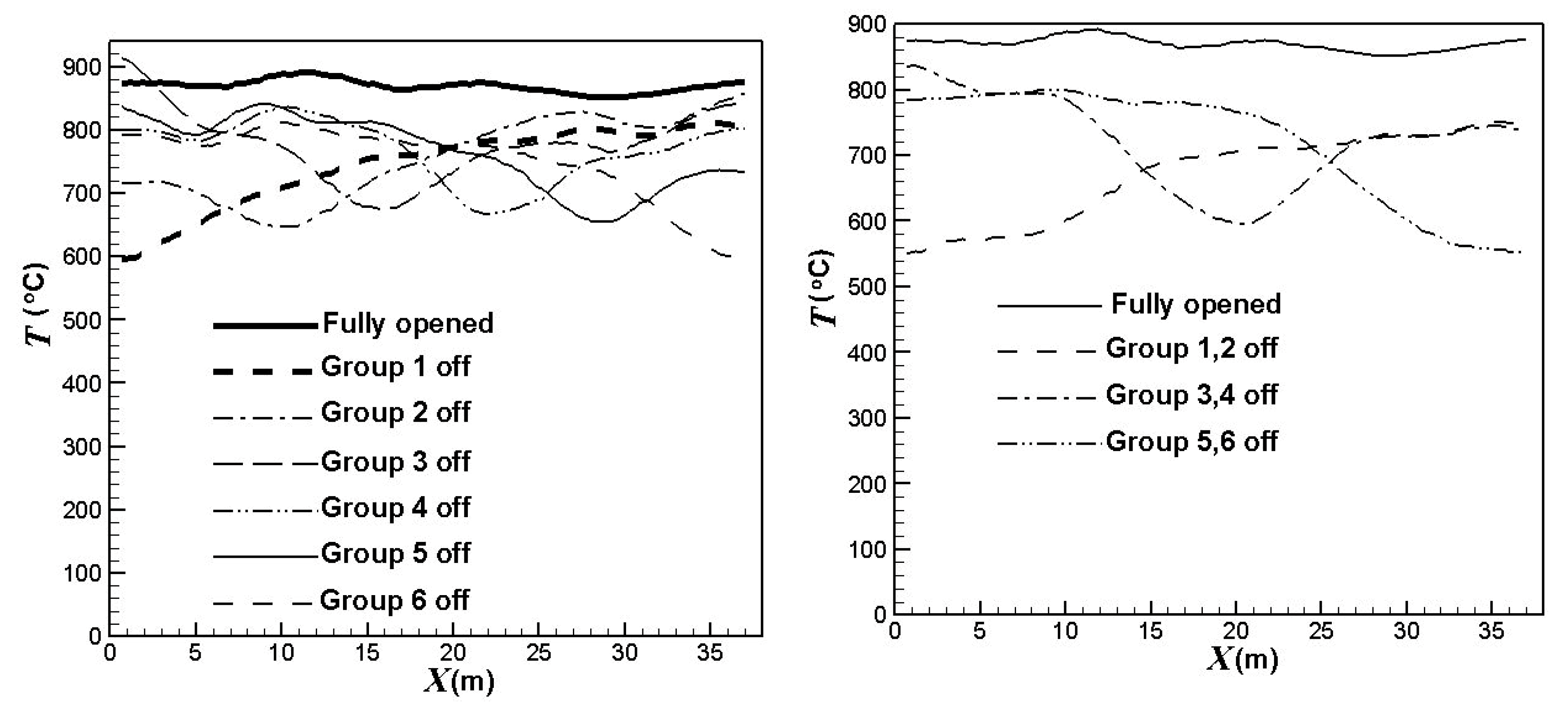
Figure 6 compares the effect of the burners on/off combinations on the average outer surface temperatures of the catalyst tubes. Obviously, the burners on/off combinations have a significant influence on the temperature profiles, as shown in Figure 6. The catalyst tube temperatures have greater reductions in the areas of burners turned off. Further, the catalyst tube temperatures reduce to a higher extent when the upstream burners are turned off. On the other hand, the catalyst tube temperatures reduce to a lower extent when the central burners are turned off. The outer surface temperatures of the catalyst tubes decrease by about 106 °C, 163 °C or 215 °C, respectively, when one group, two groups, or three groups of burners are turned off.
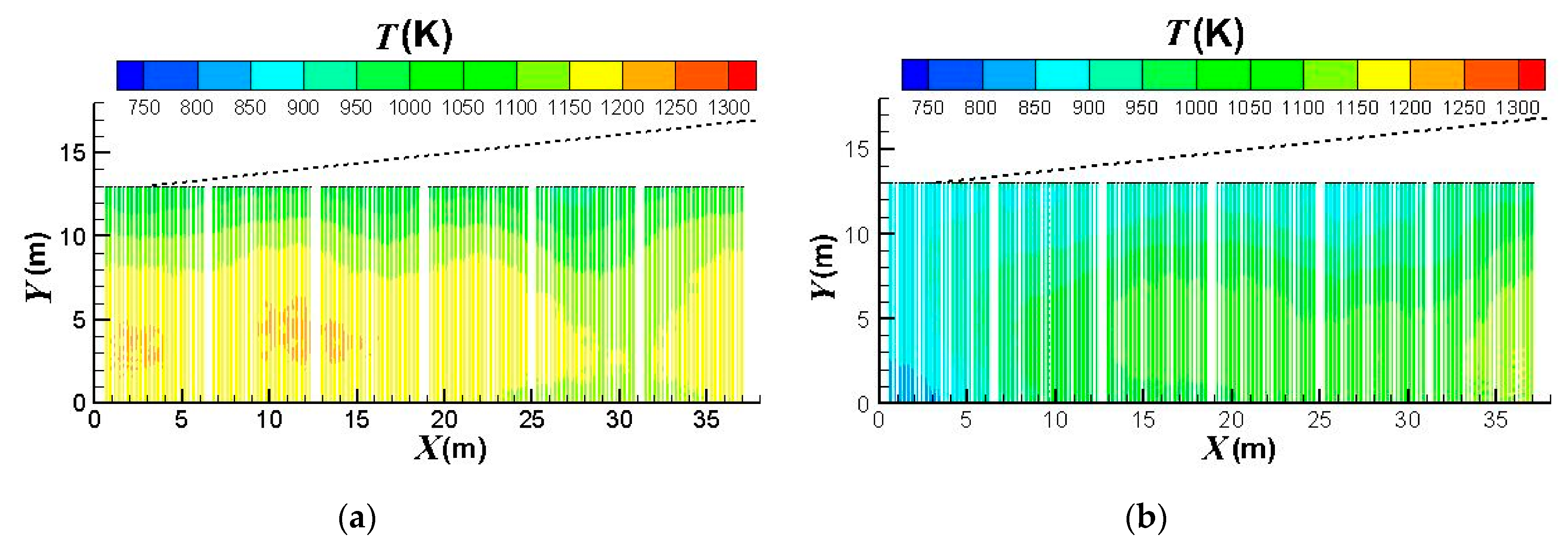
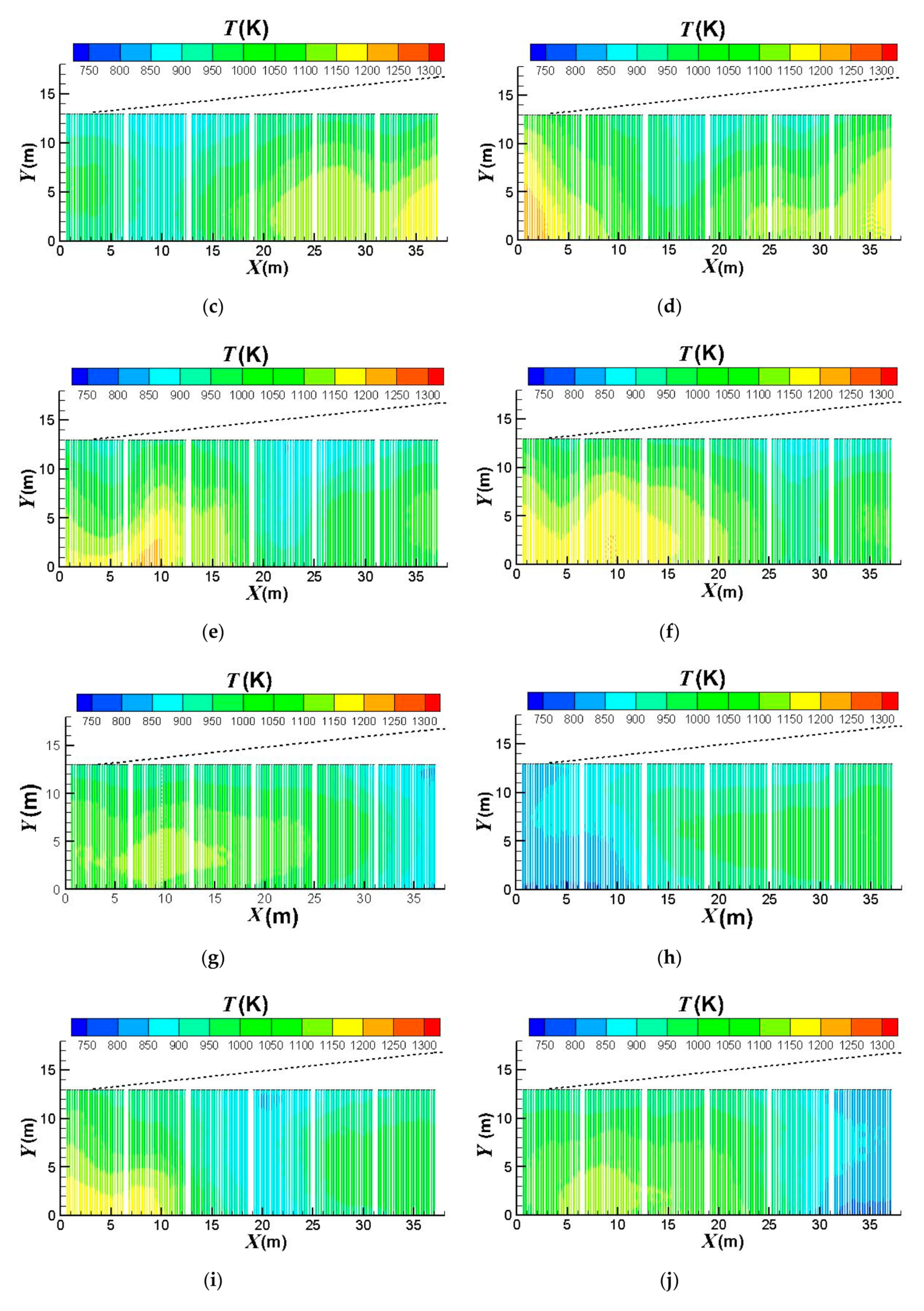
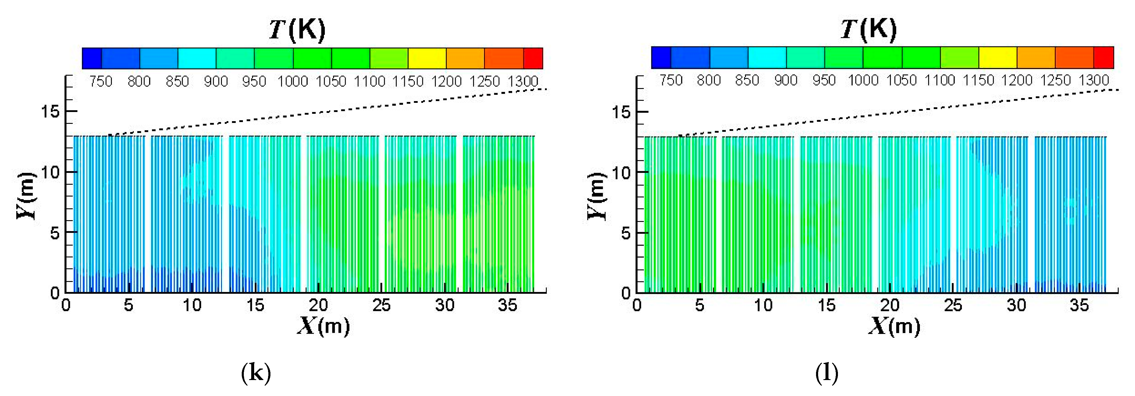
Figure 7 compares the effect of the burners on/off combinations on the outer surface temperature distributions of the catalyst tubes. It can be observed that the temperatures are higher at the lower portions of the catalyst tubes because of the weaker heat convection near the bottom wall. Further, the upstream portion of the reformer has higher temperatures. This is because the top portion (roof) of the reformer is divergent and the reformer outlet position is at the right-hand side reformer roof. Therefore, the upper portion and downstream portion of the reformer have larger heat dissipation space while the upstream portion has smaller heat dissipation space and hence higher temperatures. It is also observed that the thermal field is obviously influenced by the burners on/off combinations. For a reformer under normal operation, temperature is higher near the left-hand-side and right-hand-side walls because fluid motion is slow and heat dissipation is worse there. On the other hand, convection is better in the central area of the reformer. Therefore, turning off the burners near the left-hand-side and right-hand-side walls can mitigate the poor convection and hence yield a higher reduction in the catalyst tube temperatures. Further, heat transfer convected to the downstream area is reduced if the upstream burners are turned off; however, effect on the convection to the upstream area is minor if the downstream burners are turned off. Therefore, turning off the upstream burners can yield greater temperature reductions than turning off the downstream burners.
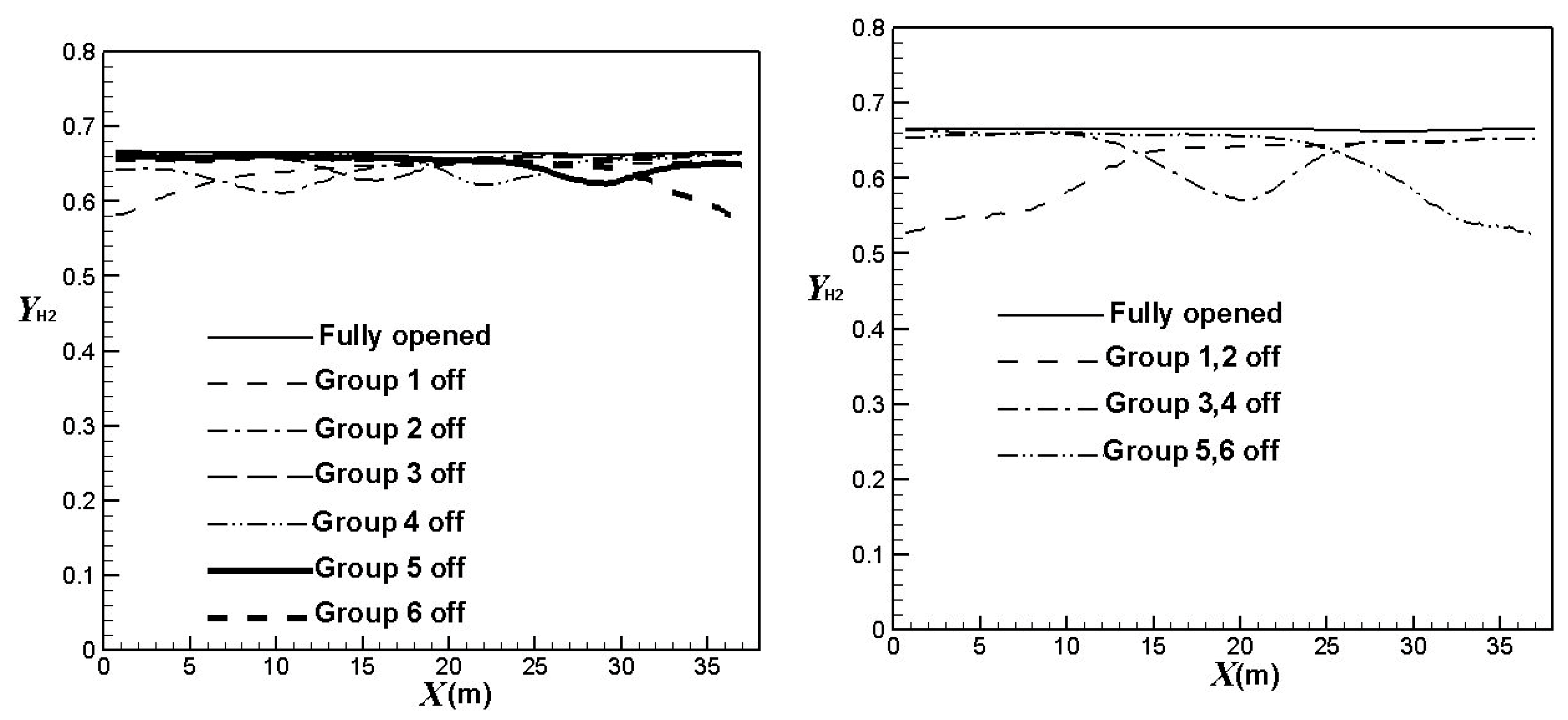
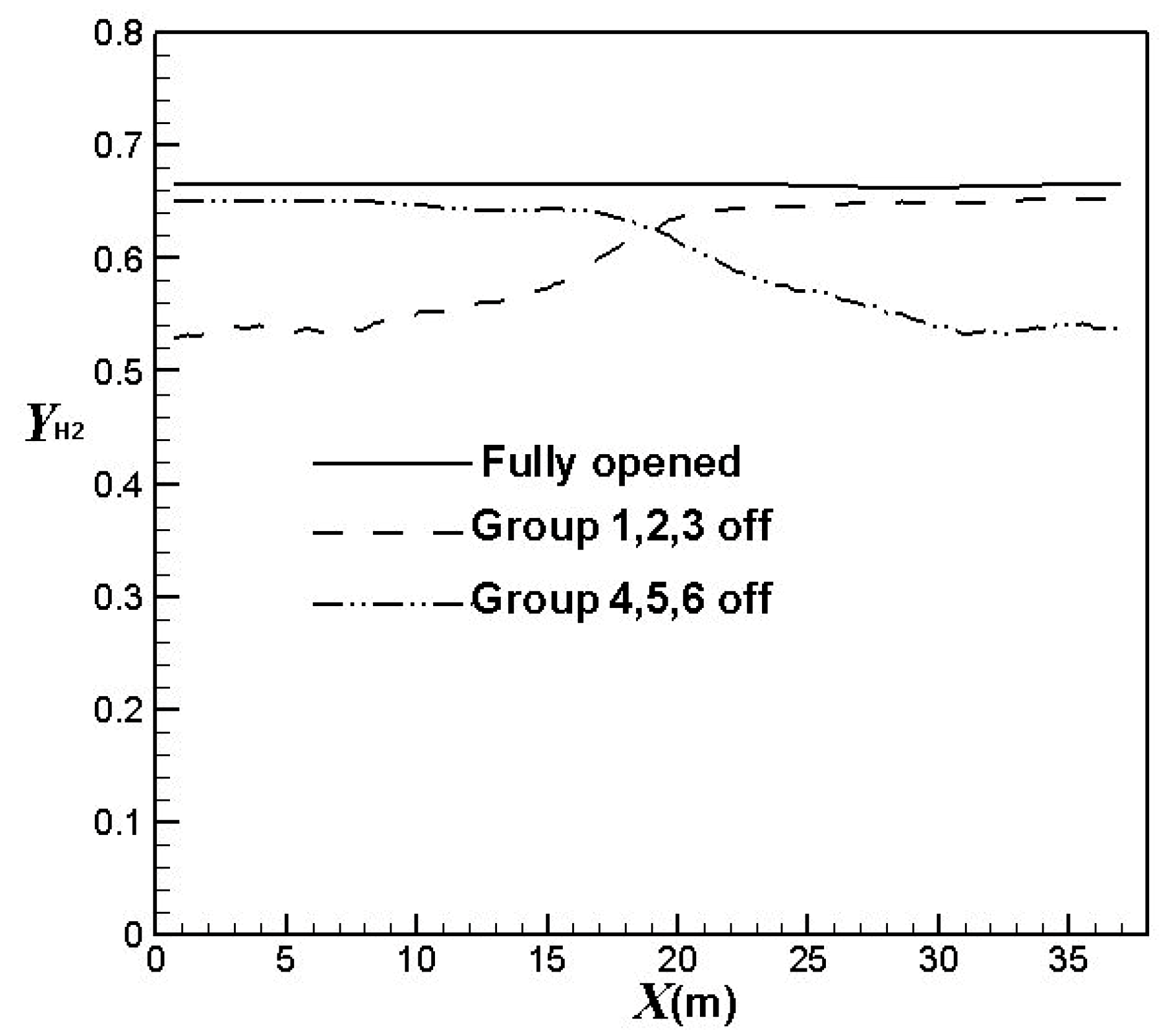
Figure 8 compares the effect of the burners on/off combinations on the hydrogen average mole fractions at the catalyst tube outlets (hydrogen yields). It is clear hydrogen yields decrease in the corresponding areas of burners turned off. The hydrogen yields reduce to a higher extent when more burners are turned off. Table 2 compares the average hydrogen yields using different burners on/off combinations. It can be observed that the hydrogen yields decrease by about 3.2%, 6.4%, or 10%, respectively, when one group, two groups, or three groups of burners are turned off. The result also shows that the hydrogen yields have greater reductions when upstream burners are turned off. On the other hand, the hydrogen yields have less reduction when central burners are turned off. The trend is similar to that of the outer surface temperatures of the catalyst tubes.
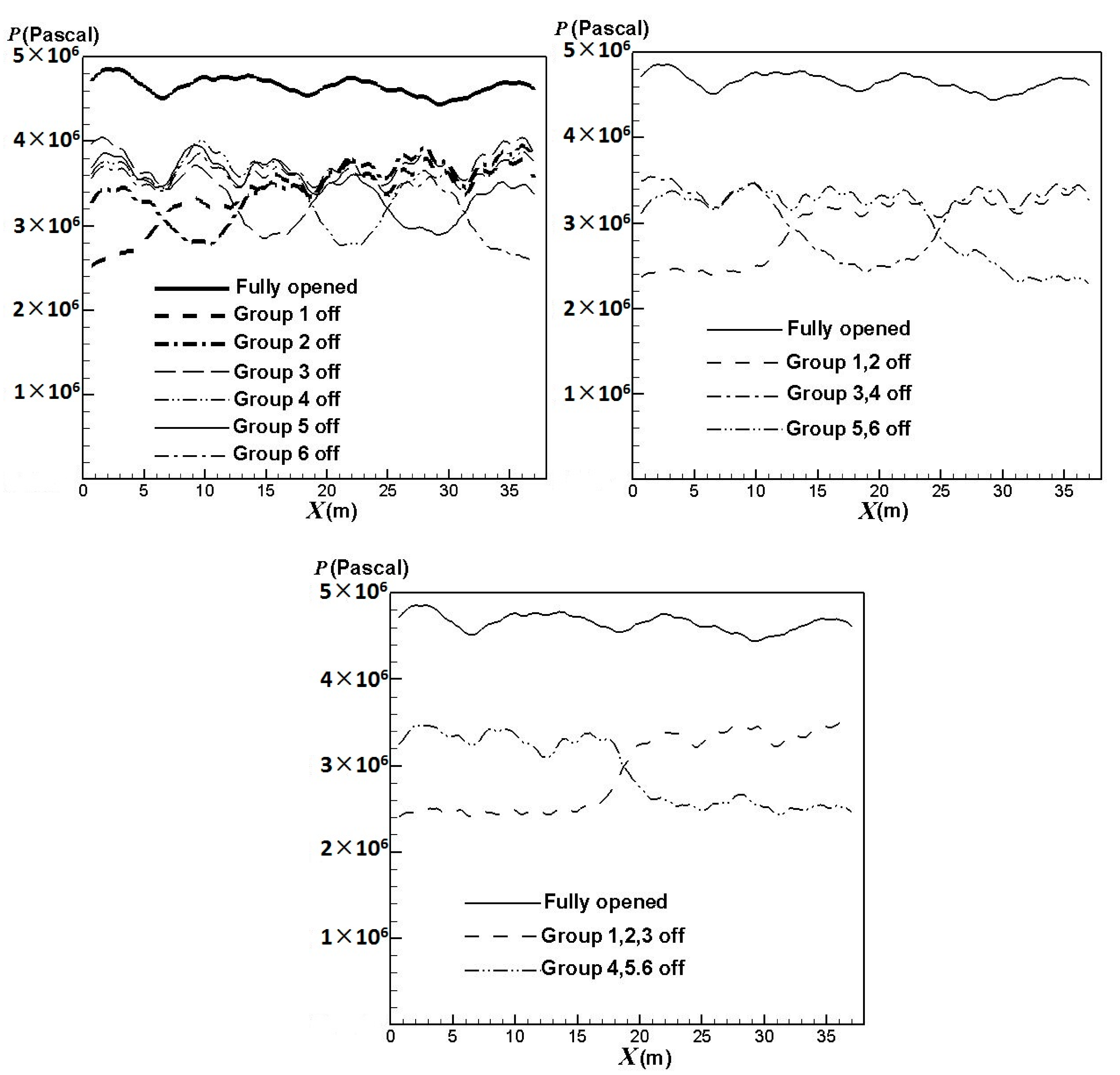
The lifetime of a catalyst tube is not only significantly affected by the catalyst tube temperature but also closely connected with the pressure inside the catalyst tube. Figure 9 compares the effect of the burners on/off combinations on the inner surface average pressures of the catalyst tubes. The result shows that the pressures have greater reductions in areas where the burners are turned off. The pressures reduce to a higher extent when more burners are turned off. Compared with Figure 6, it can also be seen that the inner surface pressures and outer surface temperatures of the catalyst tubes have similar trends.
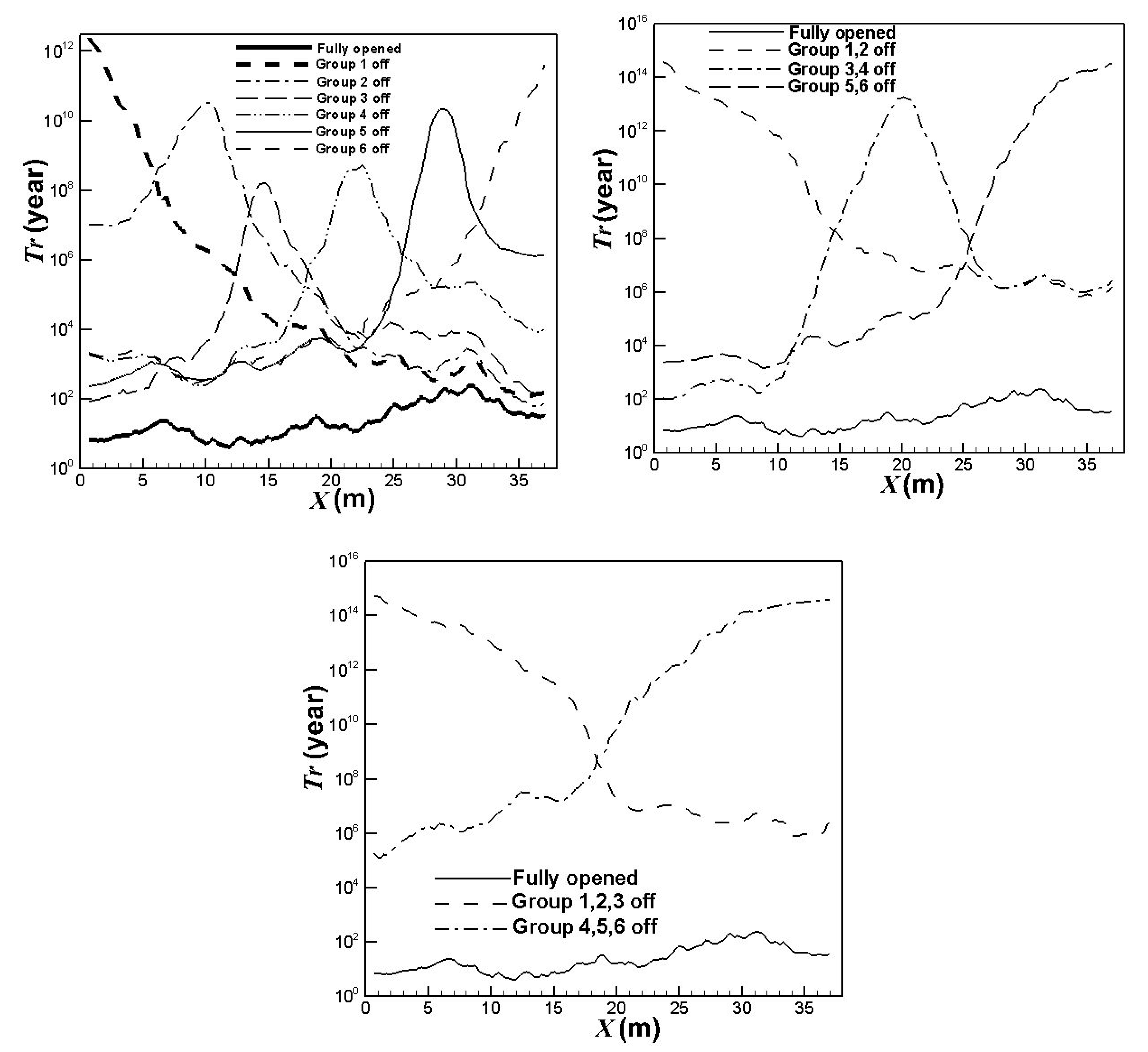
The lifetimes for the catalyst tubes of different burners on/off combinations can be estimated from the calculated maximum outer surface temperatures and maximum inner surface pressures of the catalyst tubes. The result is shown in Figure 10. It can be observed that turning off some burners is beneficial to the catalyst tube lifetime, especially for the catalyst tubes in the corresponding areas of burners turned off. The catalyst tube lifetime will be longer when more burners are turned off. Turning off the upstream burners is more efficient to the catalyst tube lifetime while turning off the central burners is less efficient. Comparing Figure 6 and Figure 8, Figure 9 and Figure 10, it can be observed that turning off some burners can reduce the catalyst tube temperatures and pressures, and increase the catalyst tube lifetimes. The main drawback is the reduction in hydrogen yields.

4. Conclusions

In this paper, we simulated a practical steam methane reformer to investigate the flow characteristics, chemical reactions, and catalyst tube lifetimes in the reformer. The burner operating mode, which has significant influence on the pressure, temperature, hydrogen yield, and the catalyst tube lifetime, is discussed. This paper aims to explore the influence of the burner operating mode on the reformer operation and to seek a feasible way of getting acceptable temperature, pressure, and hydrogen yield for a catalyst tube so that its performance and lifetime can be improved. The results of this study reveal that obvious difference exists between the simulation results of the prototype and the periodic model. Using the periodic boundary conditions, the temperature and hydrogen yield obtained are much lower than the experimental values and the inner surface pressures of the catalyst tubes are much lower than those using the real model. This may result in overestimating the catalyst tube lifetime and underestimating the reformer operation risk. The prototype should be adopted for discussion. The temperatures are higher at the lower portions of the catalyst tubes. Further, the upstream portion of the reformer has higher temperatures. The catalyst tubes in the downstream areas of the reformer have longer lifetimes while those in the upstream areas have shorter lifetimes. The catalyst tube temperature, hydrogen yield, and pressure have greater reductions when upstream burners are turned off. On the other hand, the catalyst tube temperature, hydrogen yield, and pressure have lower reductions when central burners are turned off. Turning off upstream burners is more efficient to the catalyst tube lifetime while turning off central burners is less efficient. The main drawback of turning off burners is the decrease in hydrogen yield.

Funding

This research was funded by the Ministry of Science and Technology, Taiwan, under the contract MOST108-2221-E-150-007.

Institutional Review Board Statement

Not applicable.

Informed Consent Statement

Not applicable.

Data Availability Statement

The data presented in this study are available on request from the corresponding author.

Acknowledgments

The author is grateful to the Formosa Petrochemical Corporation in Taiwan for providing valuable data and constructive suggestions to this paper during the execution of the industry-university cooperative research project under the contract 109AF-002.

Conflicts of Interest

The author declare no conflict of interest.

Abbreviations

The following abbreviations are used in this manuscript:
Cmolar concentration
Cμturbulence model constant (=0.09)
Ddiffusion coefficient
kturbulence kinetic energy (m2/s2); also reaction rate constant
Lhydraulic diameter (m)
lcharacteristic length (m)
Mmolecular weight
Ppressure (N/m2)
Rnet generation rate
Sctturbulent Schmidt number
Ttemperature (K)
Vvelocity (m/s)
Ymole fraction
Greek symbols
εturbulence dissipation rate (m2/s3)

References

  1. Leta, J.V.; Dirham, T.R.; Dobis, J.; Guo, R.; Roberts, L. A Probabilistic Approach to Fired Heater Tube Remaining Life Assessments. In Proceedings of the ASME 2015 Pressure Vessels and Piping Conference (PVP2015), Boston, MA, USA, 19–23 July 2015; p. PVP2015-45427. [Google Scholar] [CrossRef]
  2. Tawancy, H.M. Damage analysis of catalyst tube of a reformer furnace used in hydrogen production. Metallogr. Microstruct. Anal. 2012, 1, 199–207. [Google Scholar] [CrossRef]
  3. Garbiak, M.; Jasiński, W.; Piekarski, B. Materials for reformer furnace tubes: History of evolution. Arch. Foundry Eng. 2011, 11, 47–52. [Google Scholar]
  4. Liu, C.J.; Chen, Y. Variations of the microstructure and mechanical properties of HP40Nb hydrogen reformer tube with time at elevated temperature. Mater. Des. 2011, 32, 2507–2512. [Google Scholar] [CrossRef]
  5. Ray, A.K.; Kumar, S.; Krishna, G.; Gunjan, M.; Goswami, B.; Bose, S.C. Microstructural studies and remnant life assessment of eleven years service exposed reformer tube. Mater. Sci. Eng. 2011, A529, 102–112. [Google Scholar] [CrossRef]
  6. Alvino, A.; Lega, D.; Giacobbe, F.; Mazzocchi, V.; Rinaldi, A. Damage characterization in two reformer heater tubes after nearly 10 years of service at different operative and maintenance conditions. Eng. Fail. Anal. 2010, 17, 1526–1541. [Google Scholar] [CrossRef]
  7. Swaminathan, J.; Guguloth, K.; Gunjan, M.; Roy, P.; Ghosh, R. Failure analysis and remaining life assessment of service exposed primary reformer heater tubes. Eng. Fail. Anal. 2008, 15, 311–331. [Google Scholar] [CrossRef]
  8. Maharaj, C.; Imbert, C.A.C.; Dear, J. Failure analysis and creep remaining life of hydrogen reformer outlet pigtail tubes. Eng. Fail. Anal. 2008, 15, 1076–1087. [Google Scholar] [CrossRef]
  9. Ray, A.K.; Sinha, S.K.; Tiwari, Y.N.; Swaminathan, J.; Das, G.; Chaudhuri, S.; Singh, R. Analysis of failed reformer tubes. Eng. Fail. Anal. 2003, 10, 351–362. [Google Scholar] [CrossRef]
  10. Gong, J.M.; Tu, S.T.; Yoon, K.B. Damage assessment and maintenance strategy of hydrogen reformer furnace tubes. Eng. Fail. Anal. 1999, 6, 143–153. [Google Scholar] [CrossRef]
  11. Le May, I.; da Silveira, T.L.; Vianna, C.H. Criteria for the evaluation of damage and remaining life in reformer furnace tubes. Int. J. Press. Vessel. Pip. 1996, 66, 233–241. [Google Scholar] [CrossRef]
  12. Pashchenko, D. Numerical study of steam methane reforming over a pre-heated Ni-based catalyst with detailed fluid dynamics. Fuel 2019, 236, 686–694. [Google Scholar] [CrossRef]
  13. Pajak, M.; Mozdzierz, M.; Chalusiak, M.; Kimijima, S.; Szmyd, J.S.; Brus, G. A numerical analysis of heat and mass transfer processes in a macro-patterned methane/steam reforming reactor. Int. J. Hydrogen Energy 2018, 43, 20474–20487. [Google Scholar] [CrossRef]
  14. Chen, J.; Gao, X.; Yan, L.; Xu, D. Computational fluid dynamics modeling of the millisecond methane steam reforming in microchannel reactors for hydrogen production. RSC Adv. 2018, 8, 25183–25200. [Google Scholar] [CrossRef] [Green Version]
  15. Tran, A.; Pont, M.; Aguirre, A.; Durand, H.; Crose, M.; Christofides, P.D. Bayesian model averaging for estimating the spatial temperature distribution in a steam methane reforming furnace. Chem. Eng. Res. Des. 2018, 131, 465–487. [Google Scholar] [CrossRef] [Green Version]
  16. Tran, A.; Pont, M.; Crose, M.; Christofides, P.D. Real-time furnace balancing of steam methane reforming furnaces. Chem. Eng. Res. Des. 2018, 134, 238–256. [Google Scholar] [CrossRef]
  17. Tran, A.; Aguirre, A.; Crose, M.; Durand, H.; Christofides, P.D. Temperature balancing in steam methane reforming furnace via an integrated CFD/data-based optimization approach. Comput. Chem. Eng. 2017, 104, 185–200. [Google Scholar] [CrossRef]
  18. Tran, A.; Aguirre, A.; Durand, H.; Crose, M.; Christofides, P.D. CFD modeling of an industrial-scale steam methane reforming furnace. Chem. Eng. Sci. 2017, 171, 576–598. [Google Scholar] [CrossRef]
  19. Lao, L.; Aguirre, A.; Tran, A.; Wu, Z.; Durand, H.; Christofides, P.D. CFD modeling and control of a steam methane reforming reactor. Chem. Eng. Sci. 2016, 148, 78–92. [Google Scholar] [CrossRef] [Green Version]
  20. Mokheimer, E.M.A.; Hussain, M.I.; Ahmed, S.; Habib, M.A.; Al-Qutub, A.A. On the modeling of steam methane reforming. J. Energy Resour. Technol. 2015, 137, 012001. [Google Scholar] [CrossRef]
  21. Ni, M. 2D heat and mass transfer modeling of methane steam reforming for hydrogen production in a compact reformer. Energy Convers. Manag. 2013, 65, 155–163. [Google Scholar] [CrossRef] [Green Version]
  22. Yeh, C.L. Numerical analysis of an industrial-scale steam methane reformer. Adv. Technol. Innov. 2019, 4, 140–151. [Google Scholar]
  23. Fluent Inc. ANSYS FLUENT 17 User’s Guide; Fluent Inc.: New York, NY, USA, 2017. [Google Scholar]
  24. Patankar, S.V. Numerical Heat Transfer and Fluid Flows; McGraw-Hill: New York, NY, USA, 1980. [Google Scholar]
  25. Launder, B.E.; Spalding, D.B. Lectures in Mathematical Models of Turbulence; Academic Press: London, UK, 1972. [Google Scholar]
  26. Siegel, R.; Howell, J.R. Thermal Radiation Heat Transfer, 3rd ed.; Hemisphere Publishing Corporation: Washington, DC, USA, 1992. [Google Scholar]
  27. Sivathanu, Y.R.; Faeth, G.M. Generalized state relationships for scalar properties in non-premixed hydrocarbon/air flames. Combust. Flame 1990, 82, 211–230. [Google Scholar] [CrossRef] [Green Version]
  28. Launder, B.E.; Spalding, D.B. The numerical computation of turbulent flows. Comput. Methods Appl. Mech. Eng. 1974, 3, 269–289. [Google Scholar] [CrossRef]
  29. Yeh, C.L. The effect of fuel mass fraction on the combustion and fluid flow in a sulfur recovery unit thermal reactor. Appl. Sci. 2016, 6, 331. [Google Scholar] [CrossRef] [Green Version]
  30. Sugihara, S.; Kawamura, Y.; Iwai, H. Rate equation of steam-methane reforming reaction on Ni-YSZ cermet considering its porous microstructure. J. Phys. Conf. Ser. 2016, 745, 032147. [Google Scholar] [CrossRef] [Green Version]
  31. Ødegård, R.; Johnsen, E.; Karoliussen, H. Methane Reforming on Ni/Zirconia SOFC Anodes. ECS Proc. 1995, 810–819. [Google Scholar] [CrossRef]
  32. Magnussen, B.F.; Hjertager, B.H. On mathematical models of turbulent combustion. In Symposium (International) on Combustion; The Combustion Institute: Pittsburgh, PA, USA, 1976. [Google Scholar]
  33. Larson, F.R.; Miller, J. A time-temperature relationship for rupture and creep stresses. Trans. ASME 1952, 74, 765–775. [Google Scholar]
  34. Manoir Industries: Paris, France, 2012. Available online: https://www.rmg.co.id/MANAURITEXM.pdf (accessed on 9 December 2018).
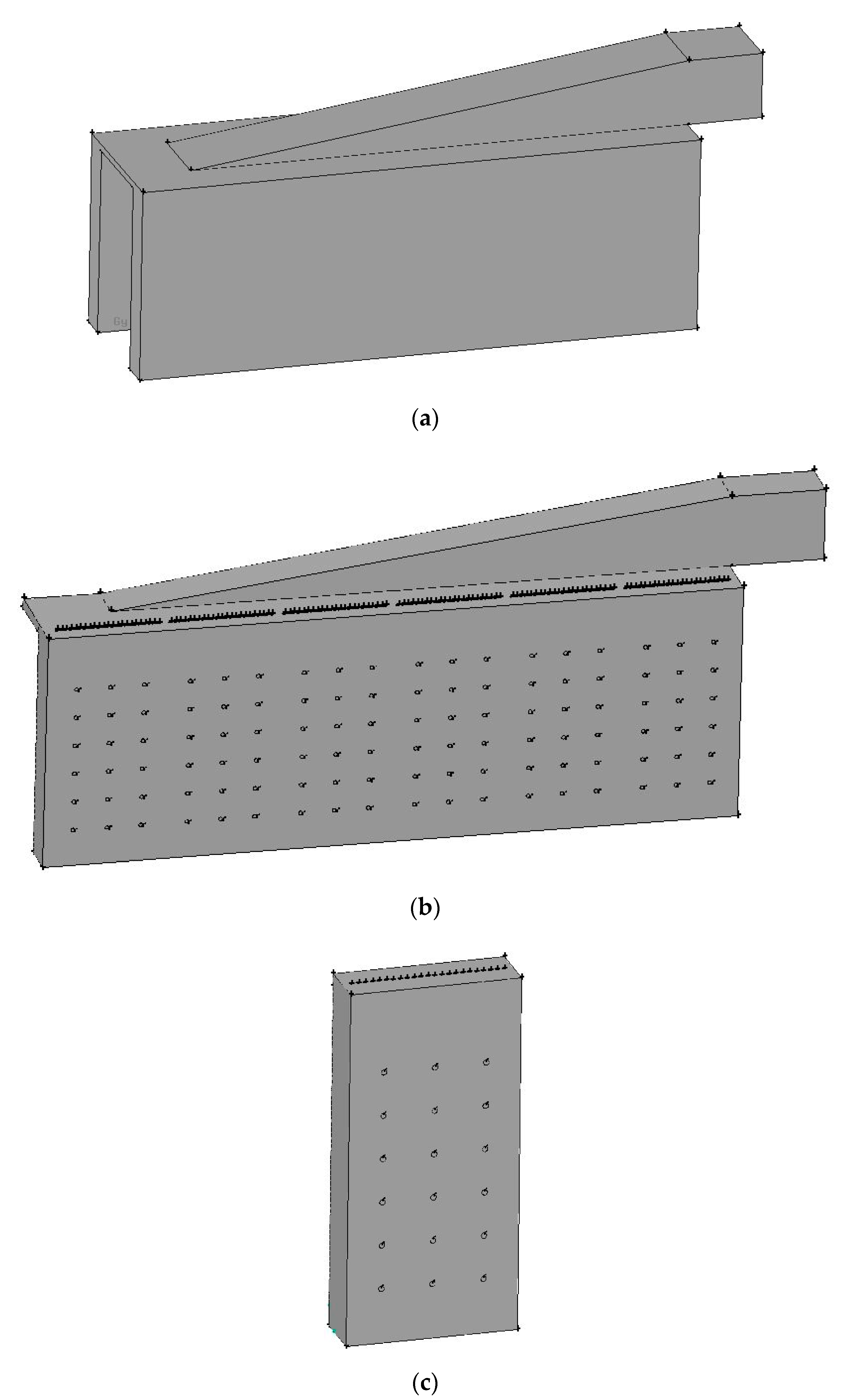
Figure 1. Steam methane reformer investigated: (a) Reformer configuration; (b) Reformer numerical model; (c) Simplified model containing one group of catalyst tubes and burners; (d) Reformer dimensions and burner positions; (e) Catalyst tube positions; (f) Burner configuration.
Applsci 11 00231 g001aApplsci 11 00231 g001bApplsci 11 00231 g001c
Figure 2. Comparison of the catalyst tube temperatures and hydrogen yields using the prototype and the periodic model: (a) Average temperatures at the outer surfaces of the catalyst tubes; (b) Hydrogen yields at the outlets of the catalyst tubes.
Applsci 11 00231 g002
Figure 3. Correlation diagram of the Larson–Miller parameter [34].
Applsci 11 00231 g003
Figure 4. Outer surface temperatures and inner surface pressures of the catalyst tubes: (a) Temperatures; (b) Pressures.
Applsci 11 00231 g004
Figure 5. Lifetimes for the catalyst tubes of the prototype reformer.
Applsci 11 00231 g005
Figure 6. Outer surface average temperatures of the catalyst tubes using different burners on/off combinations.
Applsci 11 00231 g006aApplsci 11 00231 g006b
Figure 7. Outer surface temperature distributions of the catalyst tubes using different burners on/off combinations: (a) Fully opened; (b) Group 1 turned off; (c) Group 2 turned off; (d) Group 3 turned off; (e) Group 4 turned off; (f) Group 5 turned off; (g) Group 6 turned off; (h) Group 1 & 2 turned off; (i) Group 3 & 4 turned off; (j) Group 5 & 6 turned off; (k) Group 1, 2 & 3 turned; (l) Group 4, 5 & 6 turned off.
Applsci 11 00231 g007aApplsci 11 00231 g007bApplsci 11 00231 g007c
Figure 8. Comparison of average hydrogen yields using different burners on/off combinations.
Applsci 11 00231 g008aApplsci 11 00231 g008b
Figure 9. Average inner surface pressures of the catalyst tubes using different burners on/off combinations.
Applsci 11 00231 g009
Figure 10. Lifetimes for the catalyst tubes of different burners on/off combinations.
Applsci 11 00231 g010
Table 1. Average temperatures at the front wall and back wall of the reformer.
Front Wall (°C)Back Wall (°C)
Experiment923934
Prototype Simulation891892
Periodic Model Simulation712714
Table 2. Average hydrogen yields using different burners on/off combinations.
Operating ModeHydrogen Yield
Fully opened0.670
Group 1 off0.641
Group 2 off0.647
Group 3 off0.655
Group 4 off0.654
Group 5 off0.652
Group 6 off0.644
Group 1 & 2 off0.616
Group 3 & 4 off0.637
Group 5 & 6 off0.629
Group 1, 2 & 3 off0.602
Group 4, 5 & 6 off0.604
Publisher’s Note: MDPI stays neutral with regard to jurisdictional claims in published maps and institutional affiliations.