Article

Key Technology and Experimental Study of Unequal Pitches Meshing between Metal Worm and Plastic Helical Gears

1
Beijing Engineering Research Center of Precision Measurement Technology & Instruments, Beijing University of Technology, No. 100, Pingleyuan, Chaoyang District, Beijing 100124, China
2
Dongguan Xinghuo Gear Co., LTD., Dongguan 523723, Guangdong, China
*
Author to whom correspondence should be addressed.
Appl. Sci. 2021, 11(1), 333; https://doi.org/10.3390/app11010333
Submission received: 30 October 2020 / Revised: 23 December 2020 / Accepted: 28 December 2020 / Published: 31 December 2020

Abstract

:
In traditional gear design, the design theory is based on a rigid hypothesis and is popularly adopted in the preparation of metal gear. Plastic gear designing lacks a mature design theory. Hence, scholars still follow the traditional gear design theory. There is a marked difference in the rigidity and stiffness between the conventional gear design and plastic gear features. In traditional design theory, the deformation is 0.2% (Note: To assess the material yield, conditional yield strength is calculated). Designing deformation can exceed 2% for plastic gears, and the difference can sometimes be more than tenfold. The traditional design theory cannot match the gear strength and precision in the design of plastic gear. In the case of plastic gear, due to numerous meshing teeth, the 2% deformation seen cannot be neglected and should be taken into account in the presence and absence of loading to improve the meshing condition. Improvement in the gear loading ability and reduction in the meshing noise can thus be achieved. Herein, we propose an unequal pitch design theory. The results of Finite Element Analysis (FEA) and experimental verification showed that the strength could be increased by 24% for unequal pitch design theory.

1. Preface

The worm and worm gear train has the advantages of a large speed ratio, small voltage, low noise, etc. Hence, they are widely used in the field of transmission. The technology is also applied in the preparation of window lift, rear wiper, front wiper, sunshade, seat height adjuster, recliner, among others [1].
A small volume, production of low noise, and lightweight are expected for high efficiency in this field. A strong/robust gear train is required for safe operation. The plastic gear is more prone to fail in the test due to its time-dependence characteristic (creep). Higher load capacity and higher safety factors are prerequisites in the case of gear design [2].
High load capacity in the worm gear cannot be achieved with such a small gear volume. It is imperative that the load capacity is increased, keeping the volume the same. High load capacity is equivalent to lower defective products [3].
Many scholars have investigated the load and deformation rule of the worm and helical gear tooth surface. Litvin et al. [4] analyzed the meshing rule of the metal worm and plastic helical gear, and presented a method to calculate the load on the tooth surface and the deformation at the contact point. Zhao et al. [5] presented an efficient method for calculating the load distribution rule of plastic cylindrical spur gear tooth surface and analyzed the influence of tooth surface distribution rule on gear transmission error and meshing stiffness.
Worm and worm gear train is widely used in window lift, a key product. The meshing teeth are three or four in number [6]. The load-displacement between the meshing teeth is not good, where the meshing teeth may carry half of the load. Based on the current design, we attempted to change the worm profile to achieve better load displacement and higher load capacity [7]. We did not change gearbox size and gear material, but increased bearing capacity for the gearbox. The transmission of metal worm meshing plastic helical gear can be used mainly.

2. Literature Review

Worm and Worm gear train is widely used in cross shaft transmission. It has many advantages, such as small volume, big speed ratio, low noise, simple structure, etc. [8]. The key points of the meshing between worm and worm gear are as follows [9]:
(1)
The axial module of the worm is equal to the transverse module of the worm gear.
(2)
The pressure angle of the Worm and Worm gear is the same.
According to the first key item, the worm pitch is the same as the pitch of the worm gear. This is always true when there is a steel worm meshing in the bronze worm gear. Commonly, a cutter is used to cut the bronze worm gear with the same parameters as that of the meshing worm.
The tooth thickness and the tooth addendum height of the cutter are small and different from the meshing worm owing to the tip clearance and backlash requirement [10].
In some appliances such as window lift, steel worm, and plastic helical gear train is widely used owing to its low cost, low noise, self-locking ability, and compact volume. According to DuPont’s suggestion, the helical gear strength should be calculated based on the sheer strength under the worst condition.
There are many appliances where the gear must be designed to withstand a stall torque loading significantly higher than the normal running torque. In some cases, the stall torque governs the gear design. To determine the stall torque a given gear design can handle, the material yield strength is taken into account at the expected operating temperature under stall conditions. Only a small safety factor (S = 1.3–1.5) needs to be applied if the material to be used is either Zytel® nylon resin (Dupont company, Eleutherian Mills, DE, USA) or Delrin®100 (Dupont company, Eleutherian Mills, DE, USA). The resilience of these materials allows the stall load to be distributed over several teeth [11].
Appliances like window lift gears for cars, use a steel worm, and a plastic helical gear (=worm gear), where the tooth thickness of the steel worm has been reduced in favor of the tooth thickness of the plastic gear.
In this case, the gear strength may be limited by the shear strength of the loaded teeth, as given by the following equation [12],
F max = n · f · t · τ
where n = number of teeth in (full) contact; f = tooth width (mm); t = tooth thickness (mm),
τ   =   shear   strength   =   σ y / ( 1.7 × S )   ( MPa )
where σ y = yield strength at design temperature (MPa).
The characteristic of plastic widely varies with changing temperature. The typical strain-stress curve of POM is presented in Figure 1.
Plastic can show higher deformation than steel (Figure 1). According to DuPont, Delrin100 (POM) can withstand 48 MPa at 106 times under room temperature, which implies that the deformation is ~2.5%. For steel gear, the maximum deformation allowed is about 0.2%, which forms the basis of the gear design [13].
Steel gear carrying high load must be modified according to the load. Accordingly, plastic gear should be adjusted according to the load because the deformation of plastic gear is much larger than that of the steel gear.
According to the suggestion from American Gear Manufacture Association (AGMA), the plastic gear tooth profile is shown in Figure 2 [14].

3. Meshing Theory of Steel Worm with Plastic Helical Gear

3.1. Coordinatesystem of Steel Worm Meshing Plastic Helical Gear

To study the meshing process for a steel worm and plastic helical gear, we used four coordinate systems (Figure 3). The coordinate system of the worm 1 = [ O 1 , X 1 , Y 1 , Z 1 ] , the coordinate system of plastic helical gear 2 = [ O 2 , X 2 , Y 2 , Z 2 ] , and the fixed coordinate system = [ O , X , Y , Z ] and P = [ O P , X P , Y P , Z P ] [15]. where ω 1 is the rotational angular velocity of the worm; ω 2 is the rotational angular velocity of the helical gear; V 01 is the linear velocity of the contact point; φ 1 is the angle at which the worm tooth surface rotates around the ZP axis at an angular velocity ω 1 ; φ 2 is the angle at which the tooth surface of the helical gear rotates around the Z-axis at an angular velocity ω 2 ; L 1 is the distance on that the contact point moves along the ZP axis at linear velocity V 01 .

3.2. Helical Equation of Worm

It is a line for cutter edge, the plane of the cutter edge is fixed on the plane tangent to the worm base diameter (radius r01). When it cuts the worm, the worm remains fixed. The cutter moves according to the helical route. Therefore, the route is an involute helical plane (Figure 4) [16].
Two coordinate systems are selected. The coordinate system of the cutter is U , and the coordinate system is 1 . The positions of the cutter line edge in, U as shown in Figure 5. The equation of P is given by,
r ( u ) = X U i U + Y U j U + Z U k U
X U = r 01
Y U = u cos δ 1
Z U = u sin δ 1
where δ 1 is the dip angle of the cutter, u is the parameter of the cutter, the matrix from U changes to 1
r ( 1 ) = X 1 i 1 + Y 1 j 1 + Z 2 k 1
X 1 = r 01 cos φ u + u cos δ 1 sin φ u
Y 1 = r 01 sin φ u u cos sin δ 1 cos φ u
Z 1 = u sin δ 1 + P φ u
This is the helical plane equation of the worm.

3.3. The Meshing Equation of Steel Worm with Plastic Helical Gear

To get the meshing equation (Equation (11)), the expression of a(u) on U is
a ( u ) = cos δ 1 j U sin δ 1 k U
Using the coordinate transformations, the expression of a(u) on 1 is:
a ( 1 ) = cos δ 1 sin φ u i 1 cos δ 1 cos φ u j 1 sin δ 1 k 1
During cutting worm, the relative motion between the cutter and worm V(U1) is given by,
V ( U 1 ) = P w ( U ) K ( U ) + w ( U ) K U × r ( U ) = w ( U ) ( u cos δ 1 i U + r 01 j U + P K U )
The expression of V(U1) on 1 obtained by coordinate transformations is,
V ( U 1 ) = V X 1 ( U 1 ) i 1 + V Y 1 ( U 1 ) j 1 + V Z 1 ( U 1 ) k 1
According to Equations (13) and (14), we get the expression for n on 1 as,
n = a V ( U 1 ) / | a V ( U 1 ) |
where
P = r 01 tan δ 1
To get the meshing equation, The relative speed V12 between 1 and 2 needs to be calculated.
V 12 = [ w 2 ( X 2 sin φ 2 + Y 2 cos φ 2 ) + w 1 Z 2 ] i + [ w 2 ( X 2 cos φ 2 Y 2 sin φ 2 ) + V 01 ] j [ w 1 ( X 2 cos φ 2 Y 2 sin φ 2 ) a ] k
In light of the meshing theory, it meshing each other between steel worm and plastic helical gear, it needs to meet meshing condition.
V 12 n = 0
Equations (15)–(17) when plugged into Equation (18) gives Equation (19),
( sin δ 1 sin φ 1 i 1 sin δ 1 cos φ 1 j 1 + cos δ 1 k 1 ) × { [ w 2 ( X 2 sin φ 2 + Y 2 cos φ 2 ) + w 1 Z 2 ] i + [ w 2 ( X 2 cos φ 2 Y 2 sin φ 2 ) + V 01 ] j [ w 1 ( X 2 cos φ 2 Y 2 sin φ 2 ) a ] k } = 0

4. Research Method

According to Section 3: Meshing theory of steel worm with plastic helical gear, we make some worm samples with different pitch values (Figure 6) and some plastic gears by tooling. We used UTM-4204 electronic universal testing machine and made a test fixture. The test machine verified the correctness of the theory, according to the research flow, as shown in Figure 7.

5. Load Distribution Model

It is well-known that cylinder gears need to be modified when a high load is carried. Figure 2 shows the correct method to alter the cylinder gear. This is always true when the meshing number is not more than two [17]. In some applications, such as window lift, three to four teeth carry the load in the steel worm and plastic helical gear train. Here, the working torque is further lowered than the maximum torque (stall torque). During the life test at a high temperature (~90 °C), the plastic helical gear is easily broken when maximum torque is applied.
Sometimes, a creep test is required in the case of a window lift. During these tests, the deformation of the plastic gear is inevitable, and the NONE breakage component is the key judgment rule. In other words, the deformation of the helical gear is permitted. The traditional tip relief and the root relief cannot satisfy the large deformations. Thus, to enhance the load capacity of the current steel worm and helical worm gear/helical gear, further modification is needed. From the traditional relief theory, it can be drawn that equal-stress displacement is expected when the load is carried at some temperature [18]. In this optimized design, the typical window lift is selected as the test platform, and a higher creep load capacity is the key aim. The creep rupture of Delrin®100 is listed in Figure 8.
The common requirement for a window lift is 12.74 Nm for 840 h (Window lift test standard). According to this, the same rate of deformation for all the teeth is expected to have the maximum load capacity. The same deformation rate can be obtained by modifications. A different pitch is selected to achieve the same rate of deformation. The traditional design is shown in Figure 9. The normal pitch of the worm and the helical gear is the same.
The tooth pair 2–2′,3–3′,4–4′ will be in contact in a while when the worm moves along the direction of the arrow. If only the load capacity is considered, the worm gear can be fixed.
The analysis is based on the following assumptions: The worm gear is strong enough that it would not be deformed. The material of helical gear/worm gear is Delrin®100. The structure of helical gear/worm gear is too strong to deform. In other words, the deformation is only limited at the tooth area. At the beginning of the meshing, the tooth pair 2–2′, 3–3′, 4–4′ will be in contact for a while. With the increasing load, teeth 2, 3, and 4 will deform by the same distance. Based on such assumptions, the bending deformation rate can be calculated according to the following formula [19],
ε = δ h
where ε is deformation rate; δ is bending deformation (axial moveable distance), mm, h is the distance between the contact point and root circle, mm.
In this load model, δ1, δ2, δ3 are the same, and h1, h2, h3 increase in this order. Correspondingly, ε1, ε2, ε3 decrease in the given sequence.
Let us suppose that: δ 1 = δ 2 = δ 3 = 0.06   mm ,   h 1 = 0.6   mm ,   h 2 = 1.2   mm ,   h 3 = 3   mm .
According to the calculation, the deformation rate ε1, ε2, and ε3 are 10%, 5%, and 2%, respectively, when the highest load is carried. The tooth “2” carries more than fifty-eight percent of the load. The root stress is highest for the plastic tooth, which contacts the tooth root, and the root stress is smallest for the plastic tooth, which contacts the tooth tip. The distribution of stress is shown in Figure 10.
A new design with the normal worm pitch slightly smaller than the pitch of the helical gear is presented in Figure 11.
At this load model, h 1 , h 2 , h 3 is increased and δ 1 , δ 2 , δ 3 is different in sequence. Correspondingly ε 1 , ε 2 , ε 3 is another story in sequence.
Let us suppose that: h 1 = h 1 = 0.6   mm ,   h 2 = h 2 = 1.2   mm ,   h 3 = h 3 = 3   mm δ 1 = 0.06   mm , δ 2 = 0.108   mm , δ 3 = 0.285   mm .
According to the calculation, the deformation rate ε 1 , ε 2 , and ε 3 are 10%, 9%, and 9.5%, respectively, when the highest load is carried. The tooth “1” “2” “3” carry about thirty-five percent load separately. The stress of tooth root is the same around. The distribution of stress is shown in Figure 12. According to the calculation, the load capacity of the new design worm and helical gear is more than 50 percent higher than the initial traditional design at a temperature of 90 °C. When the breakage test is done, the worm gear is deformed according to the stress-strain curve at 23 °C. The load capacity can be calculated according to the curve shown in Figure 1. However, we need to pay attention to that it can work continuously. So the pitch variation, contact ratio, and backlash should have a relationship [20].
Pnx = πmn
Pnw = πmn
ΔP = π(mnmn)
In order to work continuously, for worm and gear, it must meet the below equation,
ΔP ∗ εjn
where Pnx is the pitch for an equal worm, Pnw is-the pitch for an unequal worm, ε is contact ration, jn is the backlash for worm and the helical gear.

6. Finite Element Analysis (FEA) for Real Model

Many kinds of models are built to verify the theory, and FEA is used for the same. We built a model by kisssoft and solidworks. The pitch of the worm is changed smaller than that of worm gear. S45C is the material of worm, and the material of helical plastic gear is Delrin100. According to the strength calculation requirement, we defined a face-face contact between the worm and the helical plastic gear [21].
To ensure that the contact stress is right, a good net density is required. In this model, the worm is fixed, and the worm gear rotates along its axis. The loading curve is different in different conditions [22].
The material of the worm gear is Delrin100, and it is considered as a nonlinear material under temperatures of 23 °C in this analysis. The strain-stress table of the Delrin100 under 23 °C as Table 1.
A long tooth worm gear (helical gear) is used to verify the theory.
The support is fixed on the worm hole; the cylinder support is fixed on the hole of the plastic gear, and torque is applied to the plastic gear, it is shown in Figure 13. The materials for worm and plastic gear are defined, which are S45C for worm and POM for plastic gear. The physical characteristics of the materials are given in Table 2 [23].
Different curves and load are applied to the model to test the influence when the pitch is different from its theoretical pitch. The FEA result is shown in the following table, and the details can be obtained from the FEA report (Table 3).
Table 3 indicates that the unequal pitch will give rise to better meshing between the worm and the helical gear. The difference might lie in different meshing stiffness and different structure stiffness.
Table 3 indicates that an unequal pitch will be beneficial to the small module worm gear.
The smaller module tooth tends to deform easily than the large module tooth. Hence, the former has a lower contact stiffness than the latter.

7. Experimental Verification

To verify the unequal pitch theory, two kinds of strength test methods were adopted, including the breakage test on the fixture and the breakage test on the motor. In order to verify the unequal pitch theory proposed in this paper, by comparing the stress conditions of the equal and unequal pitch, worm and helical gear of equal and unequal pitch were processed, and the pressure testing machine, test fixture, and torsion meter were used for verification. The parameters of the worm and helical gear are shown in Table 4.

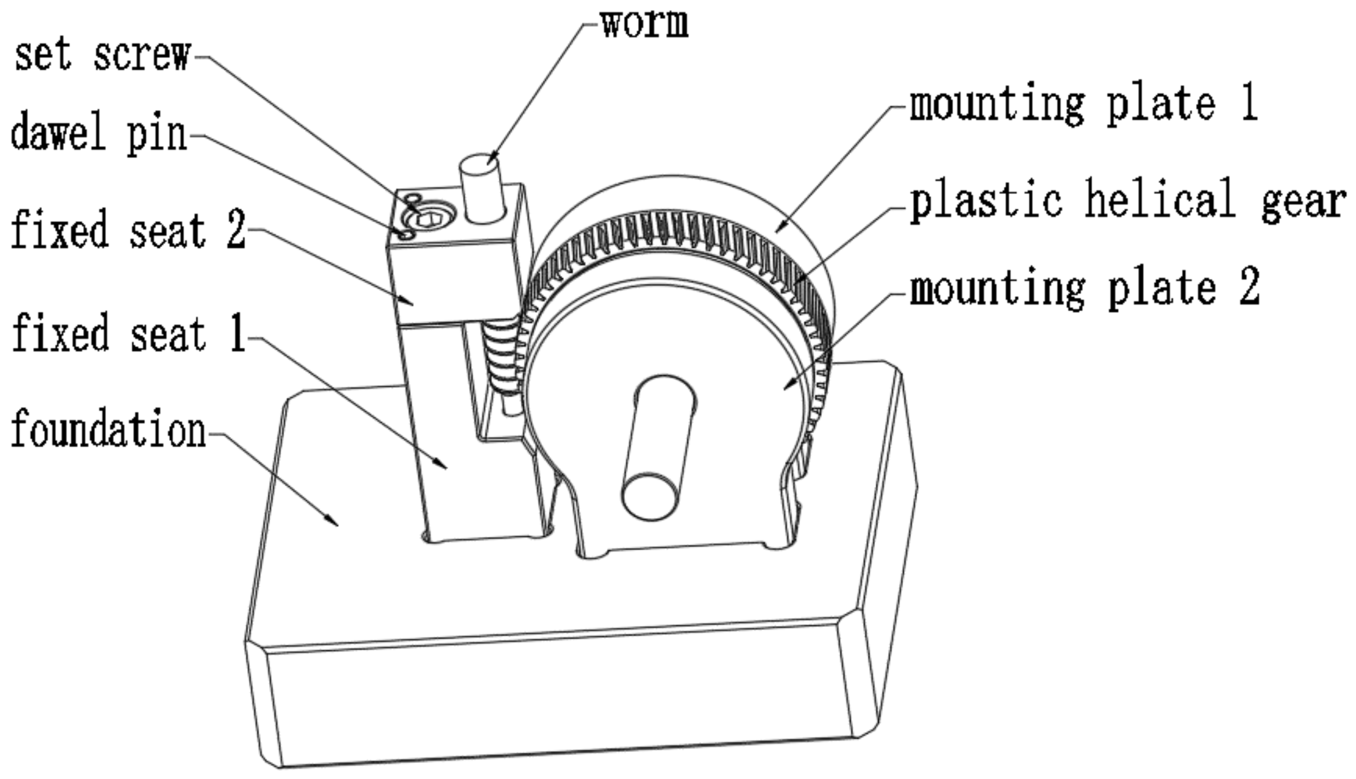
7.1. Introduction of Test Block and Test Machine

The worm and helical gear fixing device is shown in Figure 14. The right side plastic helical gear is secured by two fixed plates and is attached to the base together. On the left side, the fixing seat 1 is fixed on the base, and then the metal worm and fixing seat 2 are installed, respectively. The worm is perpendicular to the axis of helical gear through two positioning screws on fixing seat 2, and finally fixed by the pin.
As shown in Figure 15 is UTM-4204 electronic universal testing machine(Dongguan, China). It is controlled by the computer system. The computer system controls the rotation of the servo motor through the controller and the speed regulation system, and then the speed reduction system drives the beam to move through the lead screw to complete the rise and fall. Therefore, bending, shearing, stretching, and compression experiments can be completed to output the maximum stress value, tensile strength, yield strength, elastic modulus, fixed force elongation, fixed force elongation value, and elongation rate, etc. The applied load error is within ±0.5, and the output result error is within 1%, with high precision and wide application. The test process is shown in Figure 16.

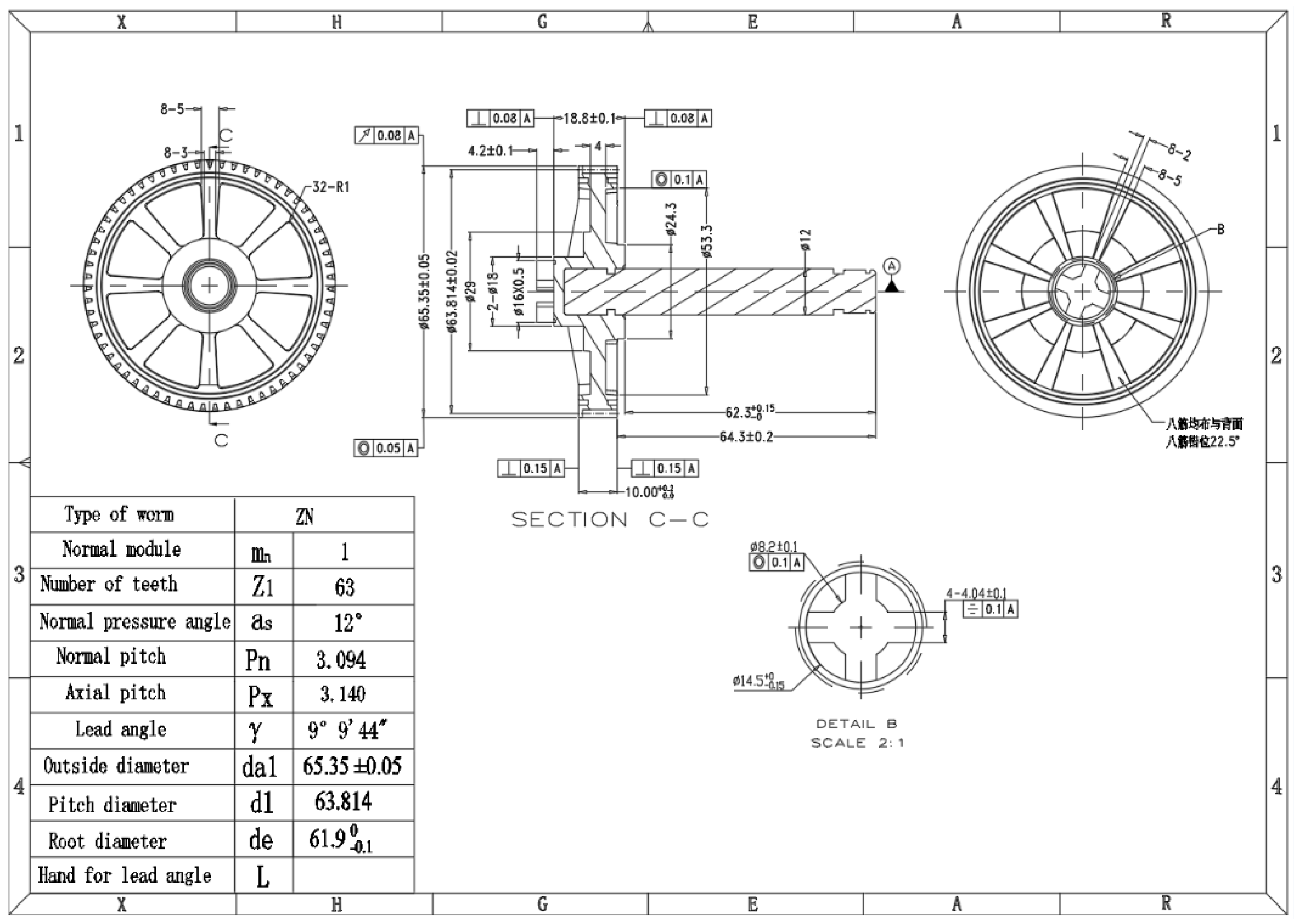
7.2. Parameter for Worm and Plastic Helical Gear

We make some sample of worm and plastic helical gear, engineering drawing as (Figure 17 and Figure 18), according to parameter and some dimension. Then we fixed on gear box.

7.3. Test Method

The equal pitch metal worm and the plastic helical gear on the universal testing machine are clamped, and the force is applied slowly until the plastic helical gear breaks. After this, the force is gradually stopped, and test data are recorded. Similarly, for an unequal pitch, the metal worms and helical gears operate in the same way.

7.4. Test Result

The standard window lift gear pair was adopted to verify the theory. The pitch of the worm is smaller than that of worm gear. It can be seen from the comparison of data in Table 5, the average maximum destructive pressure with equal and unequal pitch is 447.36 Kgf, and 563.70 Kgf, respectively. The maximum pressure of unequal pitch increased by 26% compared with equal pitch. The results show that the meshing of gears with unequal pitch can improve the root strength of gears, and can improve the service life of gears under the same working conditions, which can provide a reference for the subsequent coordination of worm and plastic helical gears.
Since the contact ratio of m = 0.8 is bigger than m = 1.0, so the force is bigger for m = 0.8. The increased rate of the breakage strength for unequal pitch worm and plastic helical gear is ((554.66 − 447.36)/447.36) × 100% = 24% for m = 0.8, and the increased rate of the breakage strength for m = 1.0 is ((415.98 − 362.53)/362.53) × 100% = 14.74%. It is shown that unequal pitch will be beneficial to the small module worm gear, as the smaller module tooth tends to deform easily than the large module tooth.

7.5. Test on Motor

In order to further verify the force of medium and unequal pitch in practice, the test was verified by a torque test in the gearbox, test model as shown in Figure 19, the torsion test equipment as shown in Figure 20, manual load, twist torsion meter, the test data as shown in Table 6. It can be seen from the table that the average torque borne by the gearbox assembled with equal pitch is 58.25 Nm, and that of the gearbox assembled with unequal pitch is 64.25 Nm. The maximum torque borne by the unequal pitch is 11.16% higher than that by the equal pitch. Through these two experiments, it can be concluded that in the matching of worm and helical gear, gear meshing with unequal pitch is better than that with equal pitch under the same working condition, which can provide an important reference for this kind of transmission design.
In conclusion, since the material was different for the gearbox, it can withstand small torque for the plastic gearbox. The increased rate of the strength for unequal pitch worm and plastic helical gear is about ((64.77 − 57.39)/57.39) × 100% = 12.86% for m = 0.8 and the increased rate of the strength is about ((79.80 − 75.12)/75.12) × 100% = 6.23% for m = 1.

8. Conclusions and Future Prospect

In this paper, the load characteristics of steel worm and plastic helical gear transmission are introduced, and according to Dupont experience, the checking formula of gear strength during helical gear transmission is obtained. The meshing theory of plastic helical gear and steel worm is deduced, and according to their meshing characteristics, the load distribution model of the tooth surface is put forward, the bending deformation rate of helical gear root is defined, and the theory of unequal pitch is put forward. Worm and helical gear are designed and manufactured according to the theory of unequal pitch. Through the finite element analysis, it is concluded that the theory of unequal pitch can improve the loading capacity of small modulus gear, but it is not suitable for large modulus gear. Finally, through the fixture damage experiment and the motor damage experiment, it is concluded that the bearing capacity of helical gear increases by 24%, and 12.86% for m = 0.8, respectively, which verifies the correctness of unequal tooth spacing theory.

Author Contributions

Conceptualization, Z.S. and J.R.; methodology, J.R., Z.F.; investigation, J.R., Z.F., J.L.; writing—original draft preparation, J.R.; writing—review and editing, Z.S., J.R. All authors have read and agreed to the published version of the manuscript.

Funding

This study is supported by the National Natural Science Foundation of China (Key Program):51635001.

Institutional Review Board Statement

The study did not require ethical approval, all data are available in public domain.

Informed Consent Statement

Informed consent was obtained from all subjects involved in the study.

Data Availability Statement

Some or all data, models, or code generated or used during the study are available from the corresponding author by request.

Conflicts of Interest

The authors declare no conflict of interest.

References

  1. Min, W.; Yong, W. Meshing transmission design of worm and helical gear in automobile micro-motor. Equip. Manuf. Technol. 2012, 11, 122–124. [Google Scholar]
  2. Deng, G.; Xu, F.; Liu, T. Experimental study on low noise for plastic helical gear and worm drive. Mech. Electr. Eng. Technol. 2010, 11, 122–123. [Google Scholar]
  3. Koide, T.; Takahama, K.I.; Miyachika, K.; Takahashi, H.; Namba, C. 405 Fatigue Life Prediction of Plastic Helical Wheel Meshed with Steel Worm. J. Mater. Metall. 2010, 2010, 105–106. [Google Scholar]
  4. Litvin, F.L.; Gonzalez-Perez, I.; Fuentes, A.; Vecchiato, D.; Sep, T.M. Generalized concept of meshing and contact of involute crossed helical gears and its application. Comput. Methods Appl. Mech. Eng. 2005, 194, 3710–3745. [Google Scholar] [CrossRef]
  5. Zhao, K.; Liu, H.; Lei, H.; Yu, X. Static simulation of worm helical gear based on ANSYS Workbench. J. Wuhan Polytechn. Univ. 2012, 31, 28–31. [Google Scholar]
  6. Du, K.; Du, X.; Zhou, Z. Contact ratio study of worm and helical gear transmission. Res. Dev. 2011, 8, 47–49. [Google Scholar]
  7. Zhang, L. Reflections on the design of engineering plastic Gear. J. Huaibei Vocat. Tech. Coll. 2009, 1, 45–46. [Google Scholar]
  8. Yun, Y.; Hu, H.; Ta, J. Changing rule of meshing force for plastic helical gear and steel worm. Mech. Drive 2018, 42, 27–32. [Google Scholar]
  9. Xu, H. Gear Manual; China Machine Press: Beijing, China, 2004. [Google Scholar]
  10. Chen, G.; Song, Z. Technology of Mechanical Manufacture; Beijing Institute of Technology Press: Beijing, China, 2007. [Google Scholar]
  11. Delrin100® Series Properties and Performance. Available online: https://www.dupont.com/knowledge/delrin-100-series.html (accessed on 5 May 2018).
  12. Chi, J.; Xiong, G. Dupont Technical Seminar. 2007. Available online: https://wenku.baidu.com/view/609b8bf9aef8941ea76e0598.html (accessed on 3 April 2018).
  13. Liu, H. Mechanics of Materials; Higher Education Press: Beijing, China, 1997. [Google Scholar]
  14. Liu, J.; Du, F. Gear modification and its application and analysis. J. Suzhou Inst. 2017, 105–108. [Google Scholar] [CrossRef]
  15. Li, L. Research on Meshing Performance of Plastic Worm Gear and Steel Worm. Available online: https://www.docin.com/p-1368083981.html 2007 (accessed on 20 July 2017).
  16. Hao, Y.; Yue, B. Meshing theory analysis of plastic helical gear and steel worm. Mech. Drive 2009, 33, 9–11. [Google Scholar]
  17. Peng, L.; Xue, H.; Wang, J. Study on gear modification and contact fatigue test. Mach. Tool Hydraul. 2017, 45, 7–10. [Google Scholar]
  18. Wang, C.; Yan, F.; Wang, F. Modification and noise reduction analysis of gear with high displacement. Tool Eng. 2017, 51, 71–75. [Google Scholar]
  19. Fan, Q.; Tang, J. Engineering Mechanics; Higher Education Press: Beijing, China, 2008. [Google Scholar]
  20. Heinz, P.B. Understanding right-angle gear backlash. Hydrocarb. Proc. 2017, 96, 17–18. [Google Scholar]
  21. Ren, J. Optimization Design and Finite Element Analysis of Gear Parameters Based on MATLAB; Jiangxi University of Science and Technology: Ganzhou, China, 2010. [Google Scholar]
  22. Li, C.; Liang, D.; Chen, B. Analysis and experimental study on meshing characteristics of plastic worm and copper helical gear. Mech. Drive 2017, 41, 58–62. [Google Scholar]
  23. Barton, P.M. Tragfaehigkeit von Schraubrad-Und Schneckengetrieben der Werkstoffpaarung Stahl/Kunststoff; Ruhr-Universitaet Bochum: Bochum, Germany, 2000. [Google Scholar]
Figure 1. Typical stress-strain curve of POM.
Applsci 11 00333 g001
Figure 2. Modified plastic gear profile.
Applsci 11 00333 g002
Figure 3. Coordinates of transmission.
Applsci 11 00333 g003
Figure 4. Schematic representation of a processed worm.
Applsci 11 00333 g004
Figure 5. Diagram of cutter edge.
Applsci 11 00333 g005
Figure 6. Worm and plastic gear samples.
Applsci 11 00333 g006
Figure 7. The schematic diagram of the research flow.
Applsci 11 00333 g007
Figure 8. Creep rupture in Delrin®100.
Applsci 11 00333 g008
Figure 9. Traditional meshing between steel worm & helical gear (a = b = c).
Applsci 11 00333 g009
Figure 10. The distribution of stress for traditional meshing between steel worm and helical gear (a = b = c).
Applsci 11 00333 g010
Figure 11. New meshing design between steel worm & helical gear(a > b > c).
Applsci 11 00333 g011
Figure 12. The distribution of stress for new meshing design between steel worm & helical gear (a > b > c).
Applsci 11 00333 g012
Figure 13. Boundaries of the FEA.
Applsci 11 00333 g013
Figure 14. Test block.
Applsci 11 00333 g014
Figure 15. Test machine.
Applsci 11 00333 g015
Figure 16. Test process.
Applsci 11 00333 g016
Figure 17. Engineering drawing for the worm.
Applsci 11 00333 g017
Figure 18. Engineering drawing for the plastic helical gear.
Applsci 11 00333 g018
Figure 19. Gearbox samples.
Applsci 11 00333 g019
Figure 20. Test on motor (ensure that the worm cannot move).
Applsci 11 00333 g020
Table 1. The short-term stress-strain curve of delrin100 at temperatures under 23 °C.
Strain (mm)Stress (MPa)
0.02550
0.0560
0.166
0.1566.5
Table 2. The physical characteristics of the materials for worm and helical gear.
MaterialPOMS45C
Physical Characteristics
Elastic modulus (MPA)31002.06 × 105
Poisson ratio0.350.3
Table 3. FEA results for different model long tooth worm & helical gear.
M = 0.8 (Same Pitch)M = 0.8 (Different Pitch)M = 1.0 (Same Pitch)M = 1.0 (Different Pitch)
Torque
(Nm)
Stress
(MPa)
Torque
(Nm)
Stress
(MPa)
Torque
(Nm)
Stress
(MPa)
Torque
(Nm)
Stress
(MPa)
1.0528.531.0522.831.0515.511.0513.75
1.9035.981.9029.701.920.521.918.10
2.938.262.9031.622.924.122.922.43
3.941.453.9034.683.930.813.928.13
545.75538.92534.42532.11
Table 4. Parameter for worm and plastic helical gear.
Normal PitchPressure AngleHelical/Lead AngleNumber of TeethOutside MeterRoot Meter
Equal pitch worm2.51312°5.93°194.3
smaller pitch worm2.46912°5.93°194.3
plastic helical gear2.51312°5.93°7260.7556.25
Equal pitch worm3.14212°9.16°17.94.36
smaller pitch worm3.09412°9.16°17.94.36
plastic helical gear3.14212°9.16°6365.3561.9
Table 5. Breakage test on the fixture.
No. of Helical GearEqual Pitch Worm & Plastic Helical GearUnequal Pitch Worm & Helical Gear
Max Breakage Force (Kgf)Max Breakage Force (Kgf)
M = 0.8M = 1.0M = 0.8M = 1.0
No. 1436.36364.21564.99413.85
No. 2430.42352.11568.95420.92
No. 3488.31361.32559.15415.33
No. 4493.26365.65565.19427.62
No. 5444.18341.59560.24411.23
No. 6456.74355.19542.31413.56
No. 7455.95349.53551.23409.23
No. 8460.4355.61538.92407.56
No. 9465.15354.69546.38418.96
No. 10451.89343.58549.21421.55
Average447.36362.53554.66415.98
Table 6. Breakage test on the motor.
No. of MotorEqual Pitch Worm & Plastic Helical Gear for GearboxUnequal Pitch Worm & Plastic Helical Gear for Gearbox
Max Breakage Torque (Nm)Max Breakage Torque (Nm)
M = 0.8M = 1M = 0.8M = 1
No. 158.2073.5065.2079.50
No. 258.5077.2064.3082.30
No. 357.3077.5060.7081.40
No. 458.2074.3064.3078.60
No. 556.2072.5066.4078.80
No. 656.5076.8066.2081.30
No. 756.1073.6065.4080.50
No. 858.2076.2065.1082.10
No. 957.6075.1064.8078.20
No. 1057.1074.5065.3075.30
Average57.3975.1264.7779.8
Publisher’s Note: MDPI stays neutral with regard to jurisdictional claims in published maps and institutional affiliations.

