CFD-Based Investigation of Lubrication and Temperature Characteristics of an Intermediate Gearbox with Splash Lubrication
Abstract
:1. Introduction
2. Cooling Mechanism
3. Experimental Setup
4. Numerical Setup
4.1. Volume of Fluid (VOF) Multiphase Model and Governing Equations
4.2. Multiple Reference Frames (MRF) Model
4.3. Computational Model and Mesh
4.4. Boundary Conditions
5. Results and Discussion
5.1. Experimental Results
5.2. Flow Field
5.3. Lubrication and Temperature Characteristics of Gears
5.3.1. Lubrication Characteristics of Gears
5.3.2. Temperature Characteristics of Gears
5.4. Lubrication and Temperature Characteristics of Bearings
5.4.1. Lubrication Characteristics of Bearings
5.4.2. Temperature Characteristics of Bearings
6. Conclusions and Future Work
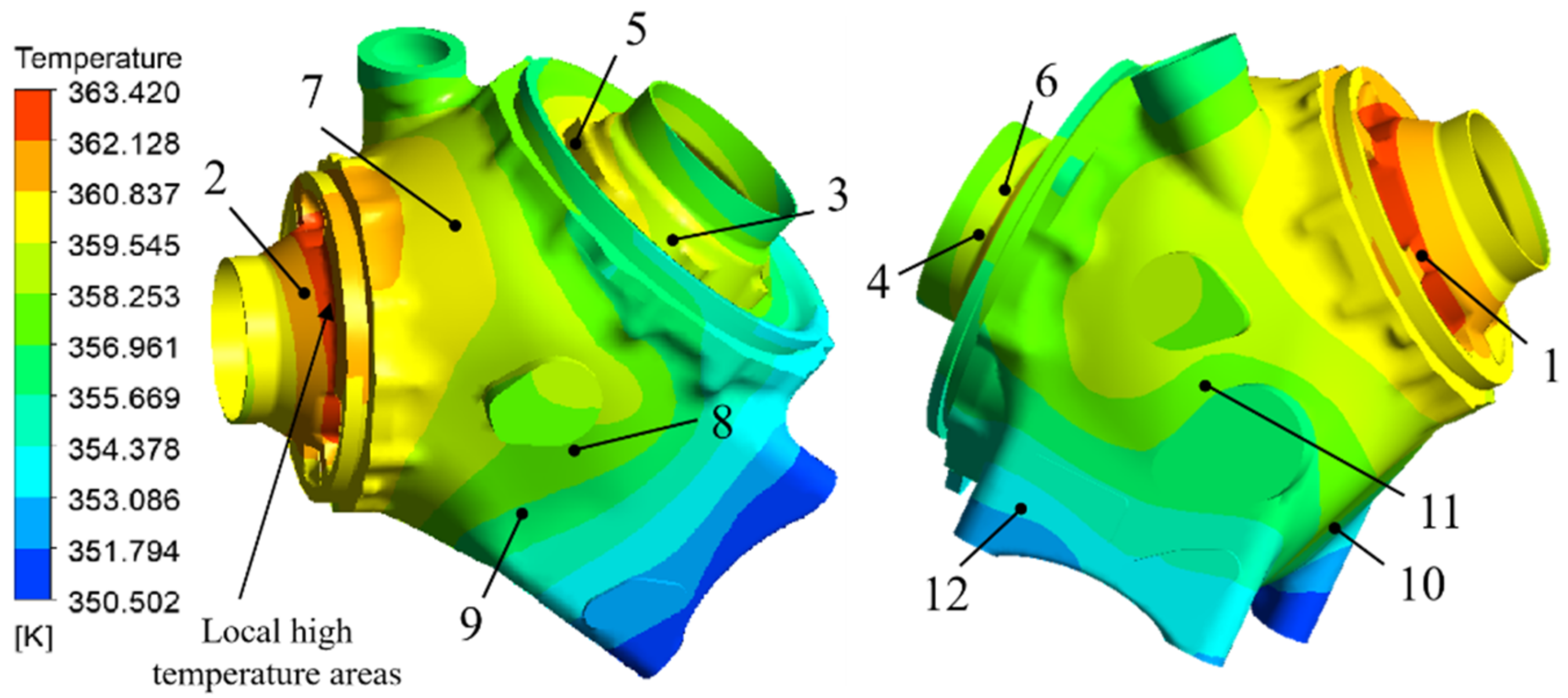
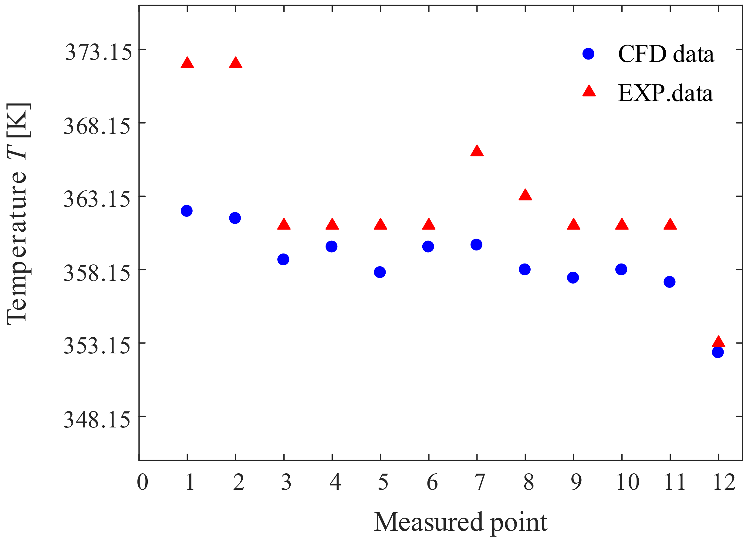
- The maximum relative error between the experimental and simulation results of the wall temperature of the casing and end covers was 10.636%. The relative error between the experimental and simulation results of the oil temperature in the oil pool was 3.180%. The oil temperature satisfied the limit requirement (<110 °C), and the oil content met the engineering application standard. The results indicate that CFD simulations can accurately predict the temperature distribution of an intermediate gearbox with splash lubrication.
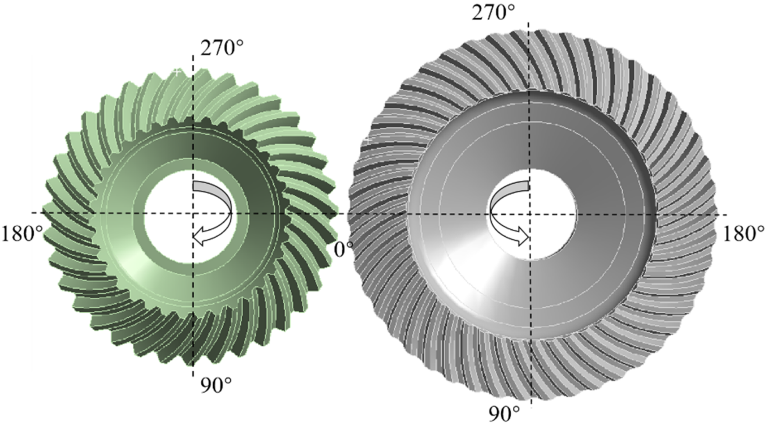
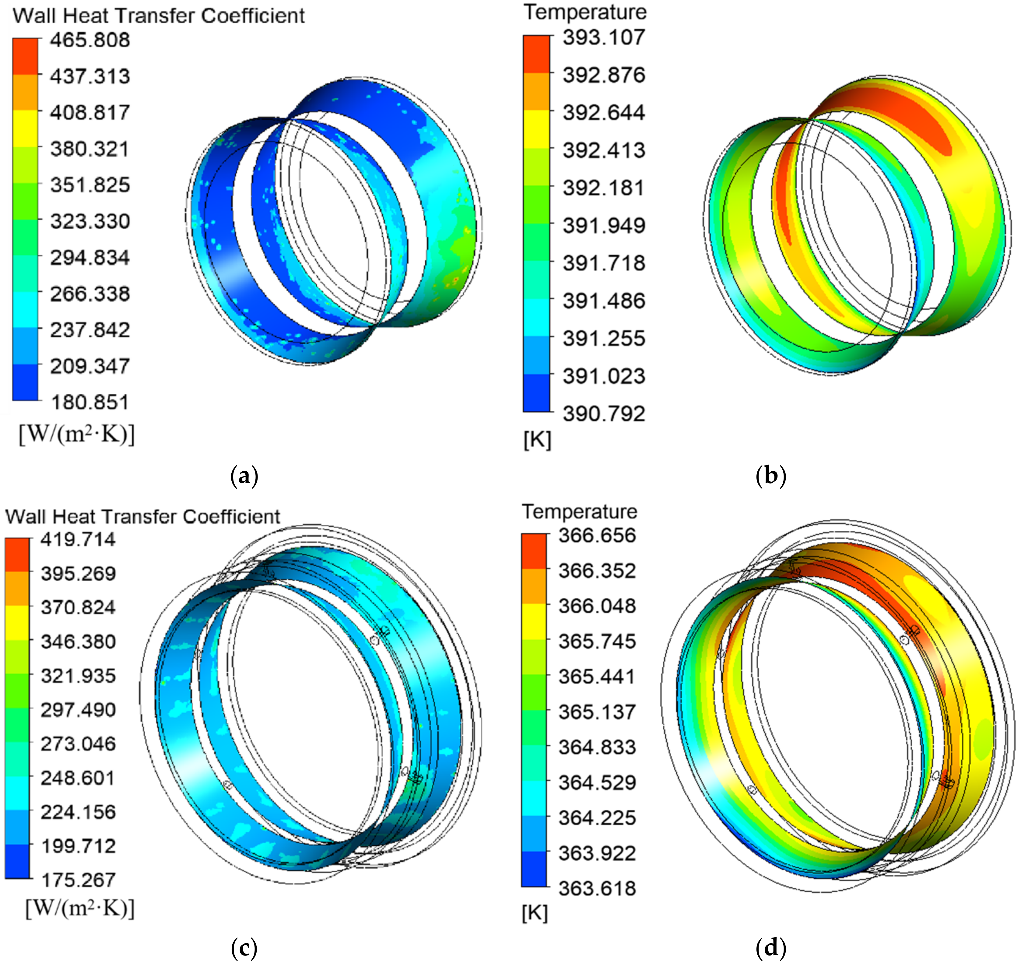
- In splash lubrication, large amounts of lubricating oil are splashed onto the tooth surface near the gear meshing area to lubricate and cool it, because the gear meshing area experiences the highest amount of frictional heat generation. A large convective heat transfer coefficient corresponds to a low gear tooth surface temperature. The tooth surface temperature of the driving gear is higher than that of the driven gear, because the heat output per unit area of the former is higher.
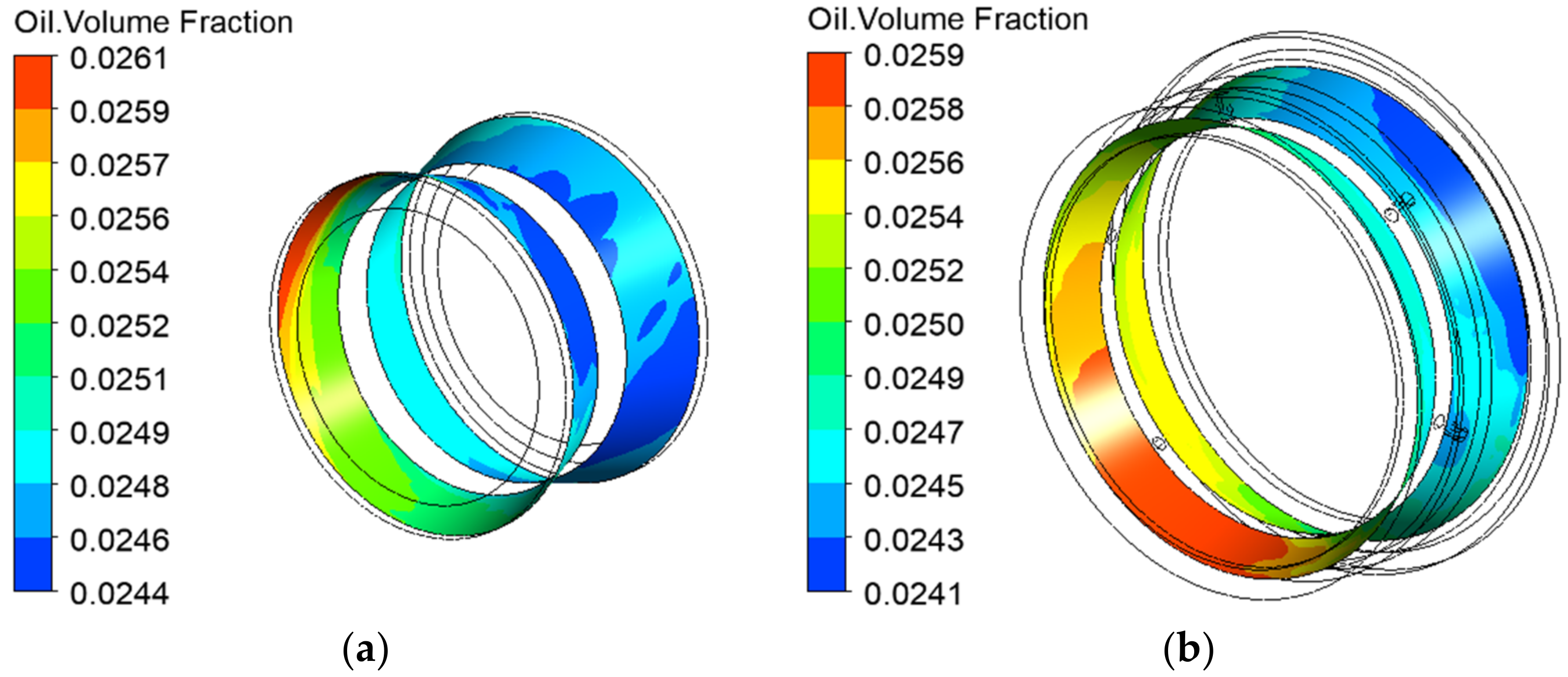
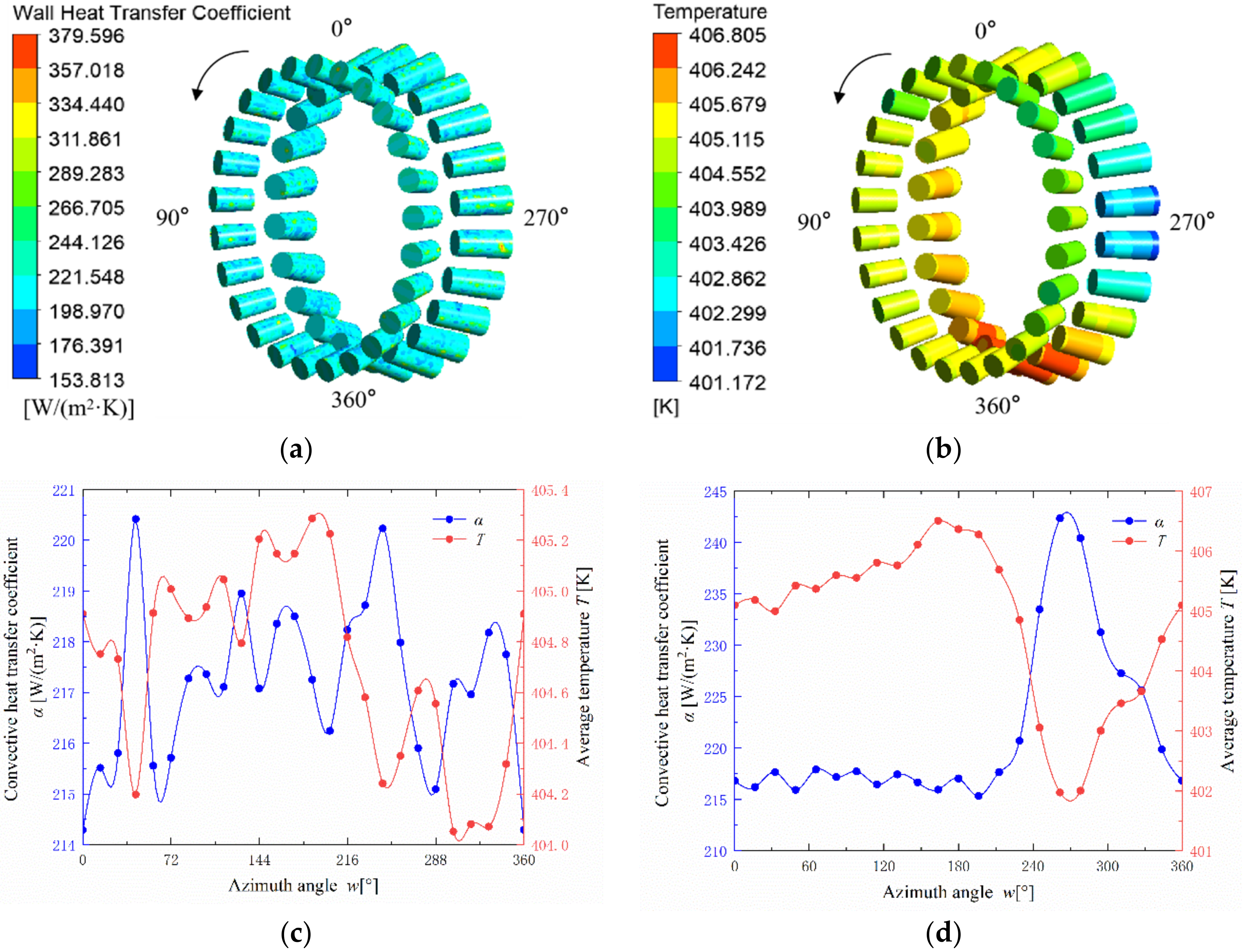
- The lubricating oil flows in the direction of rotation of the roller. Rollers with a large convective heat transfer coefficient have a lower temperature. The convective heat transfer coefficient of the roller wall is largely related to the lubrication environment of the roller, including the oil distribution inside the bearing cavity and the flow rate. Therefore, the convective heat transfer coefficient and temperature of the rollers are not determined solely by the oil volume fraction of the roller wall.
Author Contributions
Funding
Institutional Review Board Statement
Informed Consent Statement
Data Availability Statement
Conflicts of Interest
References
- Ding, W.Q. Helicopter transmission system overview. J. Aerosp. Power 2018, 3, 65. [Google Scholar]
- Bartz, W. Lubrication of Gearing; Expert Verlag: London, UK, 1993; pp. 427–430. [Google Scholar]
- Townsend, D. Dudley’s Gear Handbook, 2nd ed.; McGraw-Hill: New York, NY, USA, 1992; pp. 15.1–15.5. [Google Scholar]
- Neurouth, A.; Changenet, C.; Ville, F.; Octrue, M.; Tinguy, E. Experimental Investigations to Use Splash Lubrication for High-Speed Gears. J. Tribol. 2017, 139, 061104. [Google Scholar] [CrossRef]
- Li, W.; Tian, J. Unsteady-state temperature field and sensitivity analysis of gear transmission. Tribol. Int. 2017, 116, 229–243. [Google Scholar] [CrossRef]
- Li, W.; Zhai, P.; Ding, L. Analysis of Thermal Characteristic of Spur/Helical Gear Transmission. J. Therm. Sci. Eng. Appl. 2018, 11, 021003. [Google Scholar] [CrossRef]
- Jiang, S.; Mao, H. Investigation of the High Speed Rolling Bearing Temperature Rise with Oil-Air Lubrication. J. Tribol. 2011, 133, 021101. [Google Scholar] [CrossRef]
- Roda-Casanova, V.; Sanchez-Marin, F.; Porras-Vazquez, A. A fast finite element based methodology to predict the temperature field in a thermoplastic spur gear drive. In Proceedings of the Volume 8: 29th Conference on Mechanical Vibration and Noise, Cleveland, OH, USA, 6–9 August 2017; p. 67724. [Google Scholar]
- Wang, Y.; Niu, W.; Chen, Y.; Song, G.; Tang, W. Convection heat transfer and temperature analysis of oil jet lubricated spur gears. Ind. Lubr. Tribol. 2016, 68, 624–631. [Google Scholar] [CrossRef]
- Hu, X.; Jiang, Y.; Luo, C.; Feng, L.; Dai, Y. Churning power losses of a gearbox with spiral bevel geared transmission. Tribol. Int. 2019, 129, 398–406. [Google Scholar] [CrossRef]
- Li, L.; Versteeg, H.K.; Hargrave, G.K.; Potter, T.; Halse, C. Numerical Investigation on Fluid Flow of Gear Lubrication. SAE Int. J. Fuels Lubr. 2008, 1, 1056–1062. [Google Scholar] [CrossRef] [Green Version]
- Arisawa, H.; Nishimura, M.; Imai, H.; Goi, T. CFD simulation for reduction of oil churning loss and windage loss on aeroengine transmission gears. ASME turbo expo 2010: Turbine technical conference and exposition. Am. Soc. Mech. Eng. 2010, GT2009-59226, 63–72. [Google Scholar]
- Arisawa, H.; Nishimura, M.; Imai, H.; Goi, T. Computational Fluid Dynamics Simulations and Experiments for Reduction of Oil Churning Loss and Windage Loss in Aeroengine Transmission Gears. J. Eng. Gas Turbines Power 2014, 136, 092604. [Google Scholar] [CrossRef]
- Deshpande, S.; Joshi, H.; Madhavan, J.; Mason, P.; Wink, C. Two-Way Coupled CFD Approach for Predicting Gear Temperature of Oil Jet Lubricated Transmissions. SAE Int. J. Commer. Veh. 2018, 11, 163–170. [Google Scholar] [CrossRef]
- Yan, K.; Dong, L.; Zheng, J.; Li, B.; Wang, N.; Sun, Y. Flow performance analysis of different air supply methods for high speed and low friction ball bearing. Tribol. Int. 2018, 121, 94–107. [Google Scholar] [CrossRef]
- Hu, J.; Wu, W.; Wu, M.; Yuan, S. Numerical investigation of the air–oil two-phase flow inside an oil-jet lubricated ball bearing. Int. J. Heat Mass Transf. 2014, 68, 85–93. [Google Scholar] [CrossRef]
- Wu, W.; Hu, C.; Hu, J.; Yuan, S.; Zhang, R. Jet cooling characteristics for ball bearings using the VOF multiphase model. Int. J. Therm. Sci. 2017, 116, 150–158. [Google Scholar] [CrossRef]
- Wu, W.; Hu, C.; Hu, J.; Yuan, S. Jet cooling for rolling bearings: Flow visualization and temperature distribution. Appl. Therm. Eng. 2016, 105, 217–224. [Google Scholar] [CrossRef]
- Hirt, C.; Nichols, B. Volume of fluid (VOF) method for the dynamics of free boundaries. J. Comput. Phys. 1981, 39, 201–225. [Google Scholar] [CrossRef]
- Anderson, J.D. Computational Fluid Dynamics: The Basics with Applications; McGraw-Hill: New York, NY, USA, 1995; pp. 60–74. [Google Scholar]
- Xiao, J.L.; Zhu, E.Q.; Wang, G.D. Numerical simulation of emergency shutdown process of ring gate in hydraulic turbine runaway. ASME J. Fluids Eng. 2012, 134, 124501. [Google Scholar] [CrossRef]
- Wenjun, G.; Daniel, N.; Kun, L. A multiphase computational study of oil distribution inside roller bearings with under-race lubrication. Tribol. Int. 2019, 140, 105862. [Google Scholar]
- Orszag, S.A.; Yakhot, V.; Flannery, W.S.; Boysan, F.; Choudhury, D.; Maruzewski, J.; Patel, B. Renormalization group modeling and turbulence simulations. In International Conference on Near-Wall Turbulent Flows; Hans: Tempe, AZ, USA, 1993. [Google Scholar]
- Luo, J.Y.; Issa, R.I.; Gosman, A.D. Prediction of impeller-induced flows in mixing vessels using multiple frames of reference. IChemE Symp. Ser. 1994, 136, 549–556. [Google Scholar]
- Harris, T.A.; Kotzalas, M.N. Rolling Bearing Analysis, 5th ed.; Taylor & Francis: New York, NY, USA, 2006. [Google Scholar]
- Kerdouss, F.; Bannari, A.; Proulx, P. CFD modeling of gas dispersion and bubble size in a double turbine stirred tank. Chem. Eng. Sci. 2005, 61, 3313–3322. [Google Scholar] [CrossRef]
- Chen, Y.X.; Liu, W.J. Accessory gearbox temperature field analysis considering fuel injection lubrication. J. Beijing Univ. Aeronaut. Astronaut. 2015, 41, 1171–1176. [Google Scholar]
- Anderson, N.E.; Loewenthal, S.H. An analytical method to predict of aircraft gear boxes. Technical memorandum NASA–TM–83716 (N84–25606). 1984. Available online: https://arc.aiaa.org/doi/10.2514/6.1984-1500 (accessed on 1 November 2020).
- BS ISO/TR 14179-1. Gears–Thermal Capacity; British Standards Institution: London, UK, 2001. [Google Scholar]
- Barber, J.R. Distribution of heat between sliding surfaces. Proc. Inst. Mech. Eng. Part C 1967, 9, 351–354. [Google Scholar] [CrossRef]
- Palmgren, A. Ball and Roller Bearing Engineering, 3rd ed.; SKF Industries Inc.: Philadelphia, PA, USA, 1959; pp. 34–41. [Google Scholar]
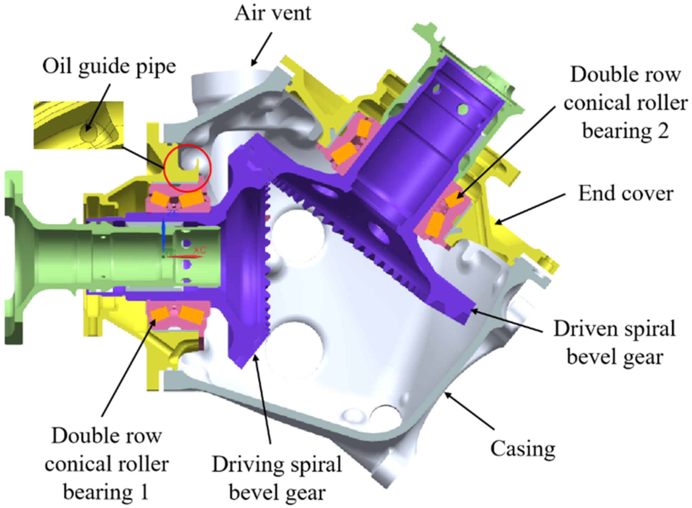
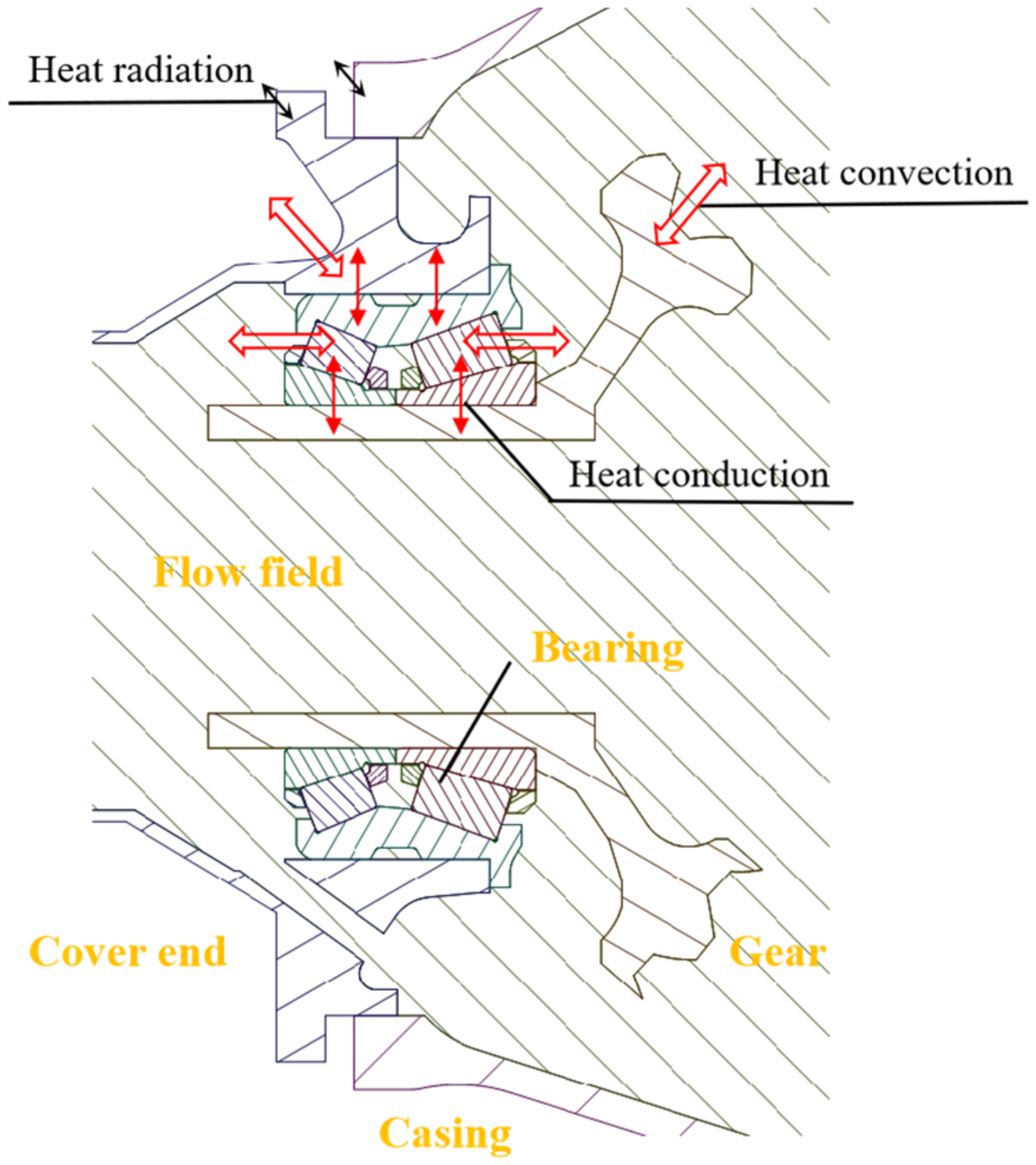
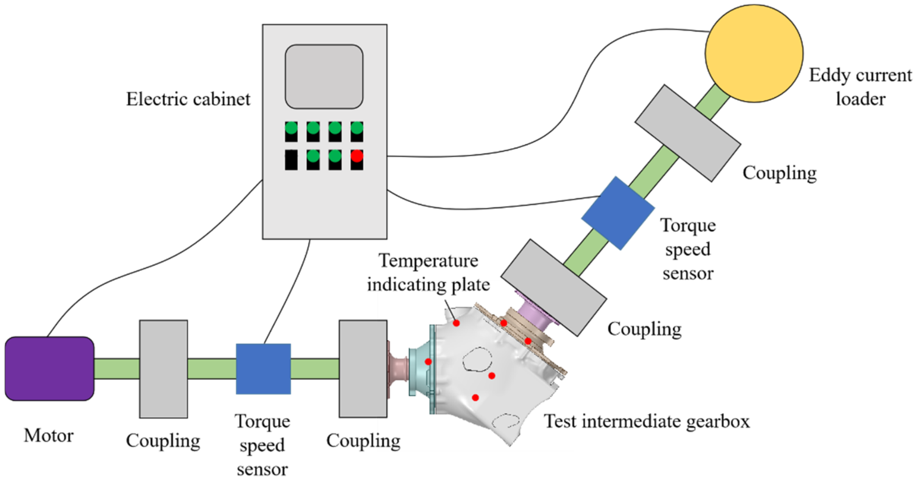
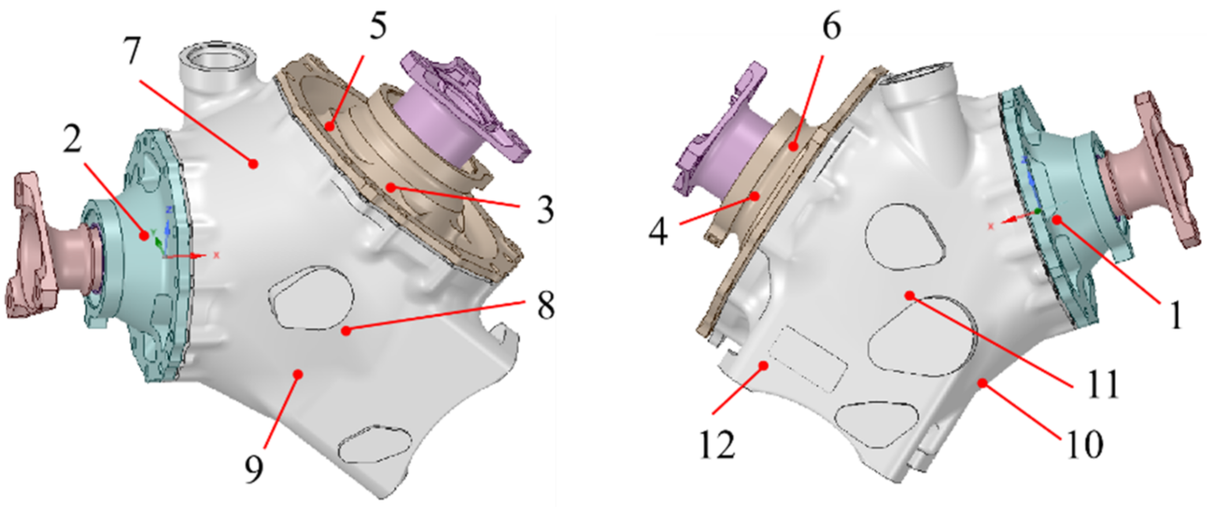




| Parameter | Driving Gear | Driven Gear |
|---|---|---|
| Hand of spiral | RH | LH |
| Number of teeth | 35 | 46 |
| Module (mm) | 3.8 | 3.8 |
| Face width (mm) | 28 | 28 |
| Pressure angle (°) | 20 | 20 |
| Mean spiral angle (°) | 35 | 35 |
| Shaft angle (°) | 128 | |
| Parameter | Value |
|---|---|
| Number of rollers | 22/25 |
| Inner diameter (mm) | 55 |
| Outer diameter (mm) | 90 |
| Width (mm) | 40 |
| Experimental Parameter | Value |
|---|---|
| Input rotational speed (r/min) | 5000 |
| Input torque (Nm) | 286.5 |
| Oil immersion depth (mm) | 17 |
| Oil density (kg/m3) | 875.15 (at 60 °C) |
| Oil dynamic viscosity (kg/m·s) | 0.0251 (at 60 °C) |
| Measured Point | Temperature (°C) |
|---|---|
| 1 | 99 |
| 2 | 99 |
| 3 | 88 |
| 4 | 88 |
| 5 | 88 |
| 6 | 88 |
| 7 | 93 |
| 8 | 90 |
| 9 | 88 |
| 10 | 88 |
| 11 | 87 |
| 12 | 80 |
| Number of Mesh Elements | Air Flow Rate of the Air Vent (kg/s) | |
|---|---|---|
| Mesh 1 | 3,361,947 | 0.1334 |
| Mesh 2 | 6,432,064 | 0.1106 |
| Mesh 3 | 10,589,597 | 0.1052 |
| Mesh 4 | 15,206,765 | 0.1031 |
| Temperature (°C) | Oil Density (kg/m3) | Oil Kinematic Viscosity (mm2/s) |
|---|---|---|
| 40 | 879.84 | 66.63 |
| 50 | 877.20 | 42.24 |
| 60 | 875.15 | 28.71 |
| 70 | 873.62 | 20.02 |
| 80 | 872.56 | 14.82 |
| 90 | 871.96 | 11.22 |
Publisher’s Note: MDPI stays neutral with regard to jurisdictional claims in published maps and institutional affiliations. |
© 2020 by the authors. Licensee MDPI, Basel, Switzerland. This article is an open access article distributed under the terms and conditions of the Creative Commons Attribution (CC BY) license (http://creativecommons.org/licenses/by/4.0/).
Share and Cite
Lu, F.; Wang, M.; Pan, W.; Bao, H.; Ge, W. CFD-Based Investigation of Lubrication and Temperature Characteristics of an Intermediate Gearbox with Splash Lubrication. Appl. Sci. 2021, 11, 352. https://doi.org/10.3390/app11010352
Lu F, Wang M, Pan W, Bao H, Ge W. CFD-Based Investigation of Lubrication and Temperature Characteristics of an Intermediate Gearbox with Splash Lubrication. Applied Sciences. 2021; 11(1):352. https://doi.org/10.3390/app11010352
Chicago/Turabian StyleLu, Fengxia, Meng Wang, Wenbin Pan, Heyun Bao, and Wenchang Ge. 2021. "CFD-Based Investigation of Lubrication and Temperature Characteristics of an Intermediate Gearbox with Splash Lubrication" Applied Sciences 11, no. 1: 352. https://doi.org/10.3390/app11010352
APA StyleLu, F., Wang, M., Pan, W., Bao, H., & Ge, W. (2021). CFD-Based Investigation of Lubrication and Temperature Characteristics of an Intermediate Gearbox with Splash Lubrication. Applied Sciences, 11(1), 352. https://doi.org/10.3390/app11010352


