Article

Method of Calculating the Compensation for Rectifying the Horizontal Displacement of Existing Tunnels by Grouting

1
Department of Civil Engineering, Zhejiang University City College, Hangzhou 310015, China
2
School of Civil Engineering and Architecture, Anhui University of Science and Technology, Huainan 232001, China
3
College of Civil Engineering and Architecture, Zhejiang University, Hangzhou 310027, China
*
Author to whom correspondence should be addressed.
Appl. Sci. 2021, 11(1), 40; https://doi.org/10.3390/app11010040
Submission received: 14 November 2020 / Revised: 14 December 2020 / Accepted: 19 December 2020 / Published: 23 December 2020

Abstract

:
Sleeve valve pipe grouting, an effective method for reinforcing soil layers, is often employed to correct the deformation of subway tunnels. In order to study the effect of grouting on rectifying the displacement of existing tunnels, this paper proposes a mechanical model of the volume expansion of sleeve valve pipe grouting taking into consideration the volume expansion of the grouted soil mass. A formula for the additional stress on the soil layer caused by grouting was derived based on the principle of the mirror method. In addition, a formula for the horizontal displacement of a tunnel caused by grouting was developed through a calculation model of shearing dislocation and rigid body rotation. The results of the calculation method proposed herein were in good agreement with actual engineering data. In summary, enlarging the grouting volume within a reasonable range can effectively enhance the grouting corrective effect. Further, with an increase in the grouting distance, the influence of grouting gradually lessens. At a constant grouting length, setting the bottom of the grouting section at the same depth as the lower end of the tunnel can maximize the grouting corrective effect.

1. Introduction

On the one hand, subway tunnels must be highly safe, but on the other hand, they can easily experience a horizontal displacement due to the excavation of the side foundation pits. Therefore, the sleeve valve pipe grouting technology is often employed for microdisturbance grouting and deviation correction. The compensatory grouting method is a mature corrective technology that is commonly used in tunnel settlement control and in the elevation of existing buildings. Furthermore, in recent years, there have been more and more projects using compensatory grouting to rectify the horizontal displacement of existing tunnels [1,2,3]. Therefore, studying the effect of compensatory grouting on rectification of the horizontal displacement of existing tunnels, as well as its influence law, is of great significance.
The main methods for investigating the compensation for tunnel deformation caused by grouting include numerical simulation, measured data analysis, and model testing. In this context, Bai et al. [2] studied the influence of sleeve valve pipe grouting on the horizontal displacement of existing tunnels through measured data analysis and numerical simulation. Zhu et al. [4] also investigated the development law of tunnel deformation under different grouting pressures and grouting positions through indoor model testing and numerical simulation. In another work, Zhang et al. [5] studied the influence of lateral tunnel grouting on the transverse deformation of a tunnel through numerical simulation and analyzed the impact of the grouting volume and range on grouting reinforcement. Because compensation grouting involves the penetration, compaction, and splitting of the slurry, the mechanism of its action is relatively complicated, and it is difficult to achieve direct research and analysis results. In this regard, Au et al. [6] pointed out that the effect of slurry injection in the surrounding soil can be examined by volume expansion of the soil in the slurry injection area. Calculation of displacement of the surrounding soil and additional stress caused by unit volume expansion requires other calculation methods. At present, the random medium theory is generally used. In this context, Zhang et al. [7] regarded surface displacement caused by grouting as a random process and assumed that the uplifting effect is the sum of the deformation effects caused by a series of radial expansions of slurry bubbles in the formation. According to the stochastic medium theory, they derived a theoretical calculation formula for surface lifting deformation and its simplified form. According to the random medium theory, Li et al. [8] considered that the influence of bubble expansion on displacement of ground surface can be equivalent to the sum of the effects of the expansion of an infinite number of tiny cells. In summary, the random medium theory is generally used to study displacement of the upper soil layer and the ground surface caused by the expansion of slurry bubbles. It can only calculate displacement of and additional stress on the soil in the upper part of the shrinkage point or the expansion point but not at the calculation point at a similar or lower depth; thus, the calculation method based on the random medium theory cannot analyze the corrective effect of grouting in the horizontal direction. Moreover, at present, there is no work on calculating the compensated level of horizontal displacement of tunnels that sleeve valve pipe grouting can achieve; hence, conducting research in this area can be of considerable importance.
This study simulated the grouting effect by calculating the volume expansion of the grouting area. To this end, a mechanical model of volume expansion of the grouting area based on the characteristics of sleeve valve pipe grouting is proposed. Based on the mirror image method [9] and combined with the research results of Wang et al. [10], formulas for the calculation of additional horizontal stress on surrounding soil caused by slurry injection of sleeve valve pipe were first derived. Formulas for calculating the horizontal displacement of existing tunnels caused by slurry injection were also developed by means of synergistic deformation models of shear dislocation and rigid body rotation. The theoretical calculation results were analyzed and compared with measured engineering data. The original calculation method was then simplified, revised, and compared with the original method. Furthermore, the effects of uniform and nonuniform expansion models on the theoretical calculations were studied. The influence of different injection volumes, injection distances, and injection depths on the compensated level of horizontal displacement of a tunnel that sleeve valve pipe grouting can achieve were studied.

2. Proposed Calculation Method

2.1. Principle of Compensated Level of Deflection

Compensation grouting is mainly used for lifting surface buildings or tunnels. Most of the current research in this field focus on analysis of the vertical lifting effect caused by grouting, with only a few studies conducted on the effect of injection-induced control in the horizontal direction. In recent years, in Shanghai, China, more and more existing tunnels have experienced horizontal deformation due to the unloading effect of surrounding projects. The sleeve valve pipe grouting technology has been used to rectify the horizontal displacement of existing tunnels [11]. The principle of horizontal corrective action of grouting is shown in Figure 1.
According to the research results of Schweiger et al. [12] and Komiya et al. [13], grouting is usually divided into two processes: compaction grouting and split grouting. In practice, these two processes often happen simultaneously. Not only are the mechanism and grouting efficiency of compaction grouting different from those of compensation grouting, but the numerical methods used for simulating these two grouting techniques are also different. Nevertheless, from an analysis of the effect of grouting, we inferred that compaction grouting and compensation grouting can cause the soil around the grouting area to expand. Schweiger et al. [12] proposed a model of volume expansion of injected soil. The model assumes that there is a spherical area with a volume of V0 around the grouting point and that the volume of the spherical area increases by ΔV after grouting. If compact grouting occurs, ΔV is the sum of the bubble volumes; if split grouting occurs, ΔV equals the sum of the volumes of splitting slurry in this area.
To sum up, grouting causes the volume of the soil in the grouting area to expand, and volume expansion of the soil applies additional stress on the surrounding soil and the existing tunnel. As the existing tunnel has already experienced some displacement before grouting, the grouting effect can correct its deformation. In the rectification of tunnel displacement, controlling the size of the correction is very important. If the corrective effect of grouting is too small, displacement of the tunnel will not be corrected. If grouting has a profound corrective effect, the existing tunnel may experience a displacement in the opposite direction. The magnitude of the grouting corrective effect is related to design variables, such as grouting volume, grouting distance, grouting section depth, and grouting section length. In the following sections, a theoretical calculation method for evaluating the corrective effect of grouting on the horizontal displacement of an existing tunnel is proposed.

2.2. Calculation of the Additional Stress Caused by Grouting

The method developed in this paper is based on derivation of the mirror method proposed by Sagaseta [9], which was originally chiefly used to calculate surface settlement and soil deformation caused by loss of the soil layer. It was later developed by Gollegger [14] to be used for calculating the compensation for displacement of soil layers caused by grout injection. Jiang and Zhao [15] employed the mirror method to calculate soil displacement caused by tunnel construction. Wang et al. [10] also used the mirror method to derive formulas for calculating the additional stress along the x-axis, y-axis, and z-axis at any point in the soil layer caused by the loss of soil due to tunnel excavation.
The traditional mirror method first transforms a semi-infinite body into an infinite body. It then uses the ground as the boundary and imagines an equal volume expansion at the original void mirror position in the infinite body. The displacement and stress at any point in the original semi-infinite body are derived by solving the normal stress and the shear stress caused by the void point and the expansion point, respectively. Based on the same idea, we just need to swap the position of the gap point with that of the expansion point in the traditional mirror method, and it can then be used to solve the additional stress at any point in the soil layer caused by expansion of the soil due to grouting. The specific analysis steps are as follows.
First, the existence of the ground is ignored, and the problem of semi-infinite bodies in actual engineering is transformed into the problem of infinite bodies. The existing volume expansion point produces normal stress σ0 and shear stress τ0 at the original ground position.
Second, by considering the ground as the boundary, an inexistent gap point of equal size is imagined at the mirror position of the original expansion point in the infinite body. The void point produces normal stress σ0 and shear stress τ0 at the original ground position.
Third, the normal stresses on the original ground generated by the above two steps balance each other out; the total shear stress is equal to 2τ0. In order to comply with actual free boundary conditions, the additional shear stress generated is reversely applied to the surface of the semi-infinite body.
The sum of the stresses generated by the above steps is the solution to the additional stress caused by the volume expansion point.
Based on the abovementioned mirror image method and combined with the research results of Wang Tao et al. [10], the spherical expansion zone with radius a at point x0, y0, and z0 produces displacement components at point x, y, and z, as expressed by
S i 1 = a 3 ( i i 0 ) 3 r 1 3 ; i = x , y , z
A gap point of equal size at its mirror position at x0, y0, and z0 produces a displacement component at point x, y, and z, respectively:
S i 2 = a 3 ( i i 0 ) 3 r 2 3 ; i = x , y , z
where r 1 = ( x x 0 ) 2 + ( y y 0 ) 2 + ( z z 0 ) 2 and r 2 = ( x x 0 ) 2 + ( y y 0 ) 2 + ( z + z 0 ) 2 .
According to the basic equations of elastic mechanics, the formulas for calculating the strain and stress generated in the soil in the above process are defined as
ε i = S i 1 i + S i 2 i ; i = x , y , z
γ x z = ( S x 1 + S x 2 ) z + ( S z 1 + S z 2 ) x
γ y z = ( S y 1 + S y 2 ) z + ( S z 1 + S z 2 ) y
σ i = E μ ( 1 + μ ) ( 1 2 μ ) ( ε x + ε y + ε z ) + 2 G ε i ; i = x , y , z
where E is the elastic modulus of the soil, μ represents the Poisson’s ratio of the soil, and G stands for the shear modulus of the soil.
By substituting Equations (1)–(5) into Equation (6), the formula for the calculation of the horizontal additional stress generated in step one and step two is expressed by
σ x 1 2 = a 3 E 3 ( 1 2 μ ) ( 1 r 2 3 1 r 1 3 ) + a 3 E ( 1 μ ) ( 1 + μ ) ( 1 2 μ ) ( x x 0 2 ) ( 1 r 1 5 1 r 2 5 ) + a 3 E μ ( 1 + μ ) ( 1 2 μ ) [ ( y y 0 ) 2 ( 1 r 1 5 1 r 2 5 ) + ( z z 0 ) 2 1 r 1 5 ( z + z 0 ) 2 1 r 2 5 ]
The shear stress on the surface generated in step one and step two satisfies τ x z = G γ x z and τ y z = G γ y z , respectively. By reversing the shear stress on the surface and integrating it through the Cerruti solution, the formula for the stress in step three is obtained as follows:
σ x 3 = a 3 π E 1 + μ lim b lim c y 0 b y 0 + b x 0 c x 0 + c z 0 ( x u ) ( u x 0 ) [ ( u x 0 ) 2 + ( t y 0 ) 2 + z 0 2 ] 5 / 2 { 1 2 μ ( r 0 + z ) 2 [ 1 r 0 ( y t ) 2 r 0 3 2 ( y t ) 2 r 0 2 ( r 0 + z ) ] 3 ( x u ) 2 r 0 5 } d u d t + a 3 π E 1 + μ lim b lim c y 0 b y 0 + b x 0 c x 0 + c z 0 ( y t ) ( t y 0 ) [ ( u x 0 ) 2 + ( t y 0 ) 2 + z 0 2 ] 5 / 2 { 1 2 μ ( r 0 + z ) 2 [ 1 r 0 ( x u ) 2 r 0 3 2 ( x u ) 2 r 0 2 ( r 0 + z ) ] 3 ( y t ) 2 r 0 5 } d u d t
The additional stress in the horizontal (x) direction caused by the volume expansion of the soil in the grouting area per unit volume is defined as
σ x = σ x 1 2 + σ x 3 4 3 π a 3
In this study, the volume expansion of the soil in the grouting area was used to simulate the influence of grouting on the surrounding soil. If we suppose that the original volume of the area to be grouted is V1, and it increases to V2 after grouting, the horizontal additional stress at any point in the soil layer caused by grouting is given by
σ x = V 2 V 1 σ x ( x , y , z ) d x d y d z
The volume of the area to be grouted can be reasonably designed according to the construction conditions and equipment in an actual project. Thus, the following section chiefly discusses how to determine soil volume after grouting (V2).
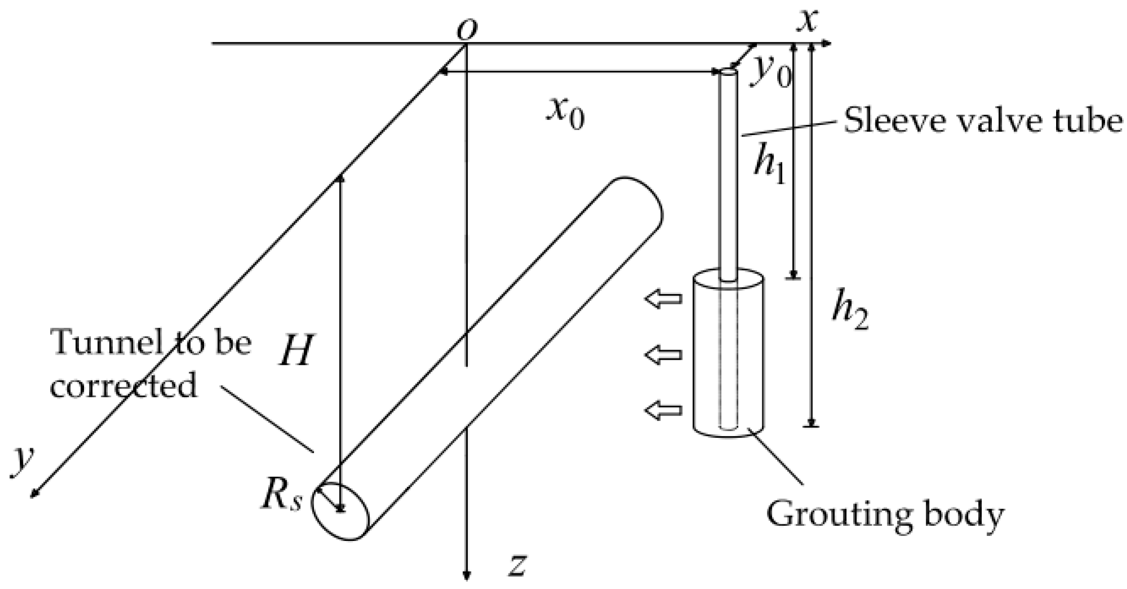
As shown in Figure 2, in rectification of the horizontal displacement of a tunnel, the sleeve valve pipe is generally driven into the soil vertically, and the slurry outlet holes are set on the sleeve valve pipe at various intervals. The sleeve valve pipe can be grouted to a certain depth range of the soil. Assuming that the grout spreads uniformly along the radial direction of the grout outlet, the sleeve valve pipe becomes the axis of grouting after injection of the grout. Thus, a grouting reinforcement area that is approximately cylindrical is formed. Assuming that the radius of the area to be grouted is R1, the radius of the cylindrical reinforcement area after grouting is R2. Supposing a constant height, the depth of the top surface of the cylindrical grouting area is h1, and the depth of the bottom surface of the cylindrical grouting area is h2. The coordinate of the corresponding plane of the sleeve valve pipe is (x1, y1). The radius of the tunnel to be rectified is Rs, and the buried depth of the axis is H. The tunnel axis lies in the y–z plane and is parallel to the y-axis.
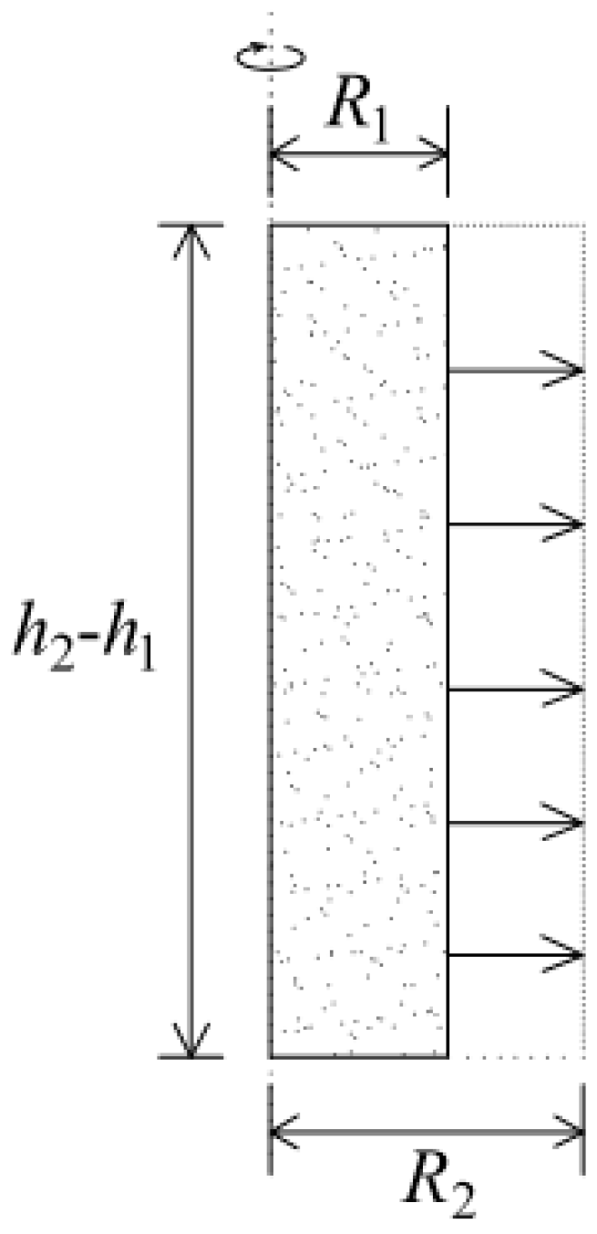
As shown in Figure 3, when the model of uniform expansion of the grouting area is used, Equation (10) can be expressed by
σ x = V 2 V 1 σ x ( x , y , z ) d x d y d z = a 2 b 2 c 2 d 2 e 2 f 2 σ x ( x , y , z ) d η d ζ d ξ a 1 b 1 c 1 d 1 e 1 f 1 σ x ( x , y , z ) d η d ζ d ξ
where a and b are the lower and upper x limits of the integral, respectively; c and d represent the lower and upper y limits of the integral, respectively; e and f denote the lower and upper z limits of the integral, respectively. Subscripts 1 and 2 indicate the state of the volume expansion of the soil before and after grouting, respectively. The formulas for calculating the lower and upper limits of the integral are defined as
a 1 = x 1 R 1 ,   b 1 = x 1 + R 1 ,   c 1 = y 1 R 1 2 ( ξ x 1 ) 2 ,   d 1 = y 1 + R 1 2 ( ξ x 1 ) 2 ,   e 1 = h 1 ,   f 1 = h 2 ,   a 2 = x 1 R 2 ,   b 2 = x 1 + R 2 ,   c 2 = y 1 R 2 2 ( ξ x 1 ) 2 ,   d 2 = y 1 + R 2 2 ( ξ x 1 ) 2 ,   e 2 = h 1 ,   f 2 = h 2 .
The rate of volume expansion of the soil (Q) before and after grouting can be defined as
Q = V 2 V 1 1 = π R 2 2 ( h 2 h 1 ) π R 1 2 ( h 2 h 1 ) 1 = ( R 2 R 1 ) 2 1
According to the work of Au et al. [6], grouting efficiency (ξinj) is related to the rate of the volume expansion of the grouting ring and the amount of grout (Vinj) as expressed by
ξ inj = V 2 V 1 V inj = Q V 1 V inj
The formula can be further transformed into
V inj = [ ( R 2 R 1 ) 2 1 ] V 1 ξ inj
Assuming that ε is the expansion of the radius of the grouting zone, it can be expressed by
ε = R 2 R 1
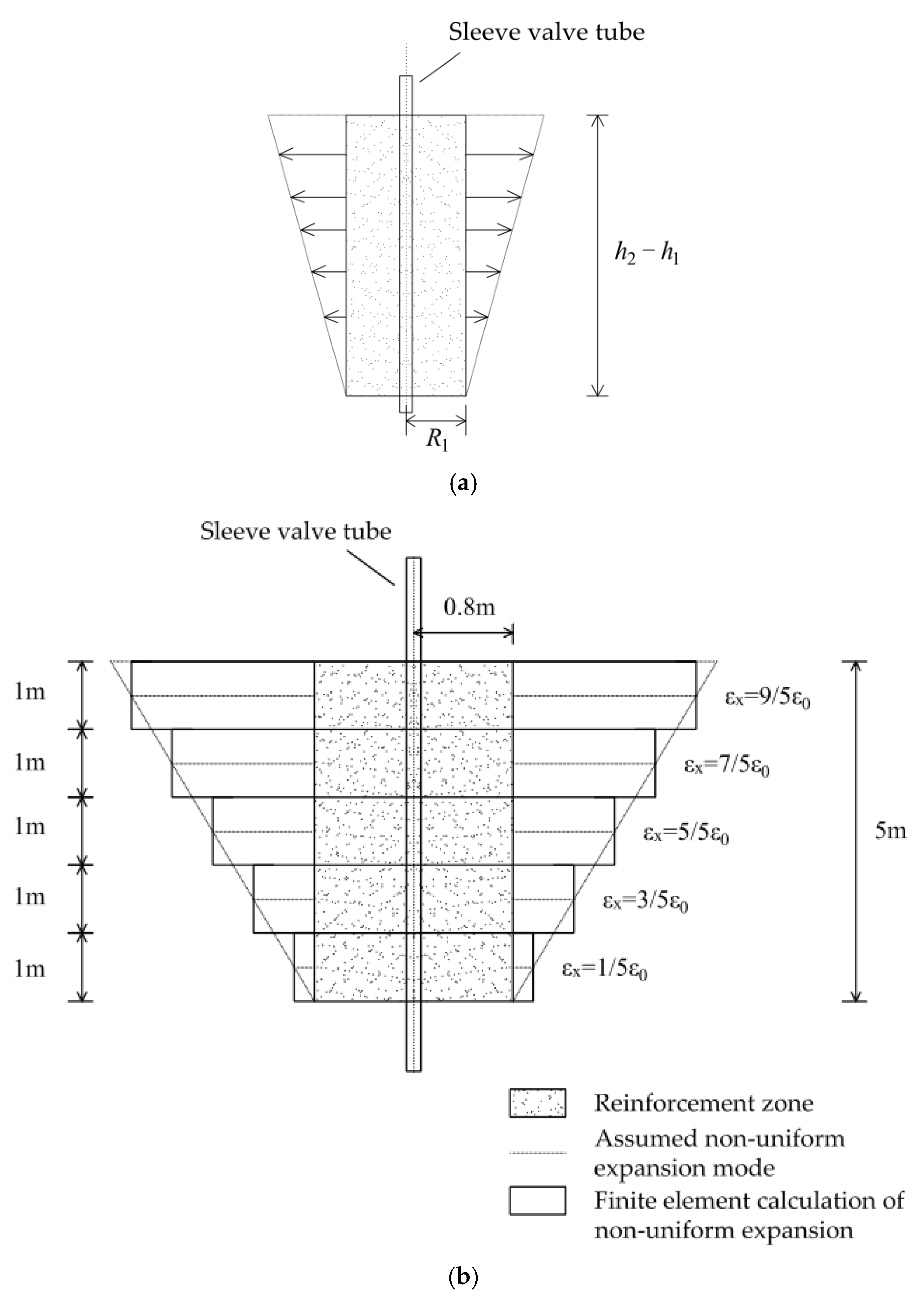
In the above study, volume expansion of the soil adopts the uniform expansion model. Assuming that the grouting area of the soil expands evenly along the horizontal and radial directions, Bai et al. [2] observed diffusion of the grout slurry during a field test. They believed that the main body of the hardened grout slurry has an approximate conical shape with a small bottom and a large top. They also reported that at a large grouting depth, the grout flows upward along the gap in the soil or the gap between the grouting pipe and soil under the action of the surrounding pressure; therefore, the grout concentrates more in the upper part of the grouting section. As shown in Figure 4a, the hardened grout slurry appears to be approximately conical. Bai et al. [2] utilized the finite element method to simulate grouting and proposed a nonuniform expansion model of grouting owing to this nonuniform distribution of grouting. As shown in Figure 4b, the grouting reinforcement area is a cylinder with a height of 5 m and a radius of 0.8 m. Having artificially divided the grouting area into five equal sections with a height of 1 m, we assume that the expansion of each section is 1.8, 1.4, 1.0, 0.6, and 0.2ε from top to bottom. During the calculations, the nonuniform expansion model can also be solved by the method presented in this work. We only need to calculate the five cylinders separately and add them together to measure the influence of the entire grouting section.

2.3. Calculation of the Horizontal Displacement in an Existing Tunnel

In this paper, calculations of the compensation for rectifying the horizontal displacement of an existing tunnel caused by grouting using the coordinated deformation model of shearing dislocation and rigid body rotation proposed by Wei and Zhang [16] are presented. This model has been employed in many works [17,18] and has been verified by the results of relevant scholars [19].

2.3.1. Energy Conversion of Deformation Process of Existing Tunnel

Relative corner movement and dislocation deformation occur between adjacent segments under the action of additional stress; they contribute to total deformation of the tunnel in the longitudinal direction. This causes the inter-ring tension and inter-ring shear generated between each of the adjacent tube sheet rings to resist deformation of the tunnel. According to analysis of the longitudinal deformation work and energy conversion of the tunnel, the additional stress caused by grouting is used to overcome resistance of the formation, the shear force between segment rings, and the tension between segment rings as follows:
W σ = W R + W S + W T
where W σ is the total amount of work done by grouting additional stress, W R represents the work done to overcome resistance of the formation, W S indicates the work done to overcome the shear force between segment rings, and W T denotes the work done to overcome the tension between segment rings.
Integrating additional stress, resistance of the formation, inter-ring shear force, and inter-ring tension along the longitudinal direction of the tunnel yields the amount of the corresponding work. This paper does not elaborate on the specific derivation process, and the detailed integration process can be found in [16]. W σ , W R , W S , and W T are expressed in Equations (17)–(20), respectively.
W σ = N D t N D t w ( y ) σ ( y ) d y
W R = N D t N D t 1 2 k D [ w ( y ) ] 2 d y
W S = m = N N 1 1 2 k s ( 1 j ) 2 [ w ( ( m + 1 ) D t ) w ( m D t ) ] 2
W T = m = N N 1 k t j 2 D 2 6 D t 2 [ w ( ( m + 1 ) D t ) w ( m D t ) ] 2
where N is the number of segment rings on one side of the tunnel affected by the additional stress at the center point, ks represents the shear stiffness between the tunnel segment rings, kt stands for the tensile stiffness between the tunnel segment rings, D is the tunnel diameter, Dt denotes the width of the segment ring, j indicates the proportional coefficient of the rigid body rotation effect of the segment ring, w(y) is the horizontal displacement of the tunnel, and m and m + 1 are the serial numbers of two adjacent segment rings.

2.3.2. Derivation of Displacement Function of Existing Tunnel

According to the energy variation method, we can assume that the horizontal displacement function of the shielded tunnel is given by
ω ( y ) = n = 0 a n cos ( n π y N D t ) = { T n ( y ) } A T
where T n ( y ) = { 1 , cos ( π y N D t ) , cos ( 2 π y N D t ) , , cos ( n π y N D t ) } , A is the undetermined coefficient matrix in the displacement function, A = { a 0 , a 1 a n } T , and n represents the expansion order of the Fourier series.
Taking the derivation of each undetermined coefficient on both sides of Equation (16) yields
W σ a i = W R a i + W S a i + W T a i
where a i is the ith element in matrix A, and i = 1, 2, 3, ···, n.
Substituting Equations (17)–(20) into Equation (22) leads to
{ m = N N 1 [ ( k s ( 1 j ) 2 + k t j 2 D 2 3 D t 2 ) ( w ( ( m + 1 ) D t ) w ( m D t ) ) a i ( T n ( ( m + 1 ) D t ) T n ( m D t ) ) ] + N D t N D t k D w ( y ) a i T n ( y ) d y } × A T = N D t N D t σ ( y ) { T n ( y ) } T d y
Simplifying Equation (23) into a matrix form results in Equation (24):
( [ K r ] + [ K s ] ) A T = { σ x } T
where [ K r ] A T is the interaction effect between the segment rings, [ K r ] stands for the matrix of the stiffness between the segment rings, [ K s ] A T represents the effect of the resistance of the formation, [ K s ] is the soil (formation) stiffness matrix, and { σ x } T indicates the effect of horizontal additional stress on the tunnel caused by grouting.
From Equation (24), undetermined coefficient matrix AT can be obtained as follows:
A T = ( [ K r ] + [ K s ] ) 1 { σ x } T
Substituting AT into Equation (21), the calculation function of the lateral horizontal displacement of the tunnel can be expressed by
ω ( y ) = { T n ( y ) } A T
The above calculations were programmed and calculated by MATLAB®, and an expansion coefficient (n) of 10 could fulfill the calculation accuracy requirements.

3. Analysis and Reliability Verification of an Engineering Case

3.1. Operating Conditions

This study considered rectification of the lateral deviation of a tunnel in Tianjin, China, as an engineering case study [2,11]. As shown in Figure 5, the tunnel is located next to the ground wall of a foundation pit project. Due to the unloading effect of the foundation pit excavation, the tunnel has undergone some horizontal deformation. In order to correct the horizontal displacement of the tunnel, two sleeve valve pipes were set at a distance of 10.3 m from the side wall of the tunnel. The diameter of the sleeve valve pipes was 30 mm, and the distance between the two sleeve valve pipes was 4 m. In addition, the two sleeve valve pipes worked simultaneously during grouting. The grouting volume of a single sleeve valve pipe was 4 m3, and the grouting depth ranged from 15 to 20 m. The selected grouting reinforcement area was a cylinder with a height of 5 m and a radius of 0.8 m. The outside diameter of the tunnel that should be deflected was 6.2 m. The tunnel was lined with tubular C50 concrete precast sheets. The depth of the soil layer of the tunnel and grouting section was in the range of 13.8–20 m, and the soil layer was all silty clay. The other relevant parameters of the tunnel were as follows: j = 0.3, ks = 7.45 × 10⁵ kN/m, kt = 1.94 × 10⁶ kN/m, N = 175, and Dt = 1.5 m. The compressive modulus (Es), the elastic modulus (E), the tunnel equivalent bending stiffness (EI), and the Poisson’s ratio (μ) of the soil were 9.32 MPa, 25 MPa, 1.1 × 10⁸ kN/m2, and 0.3 respectively.

3.2. Analysis of Theoretical Calculation Results

3.2.1. Reliability Verification of the Proposed Method

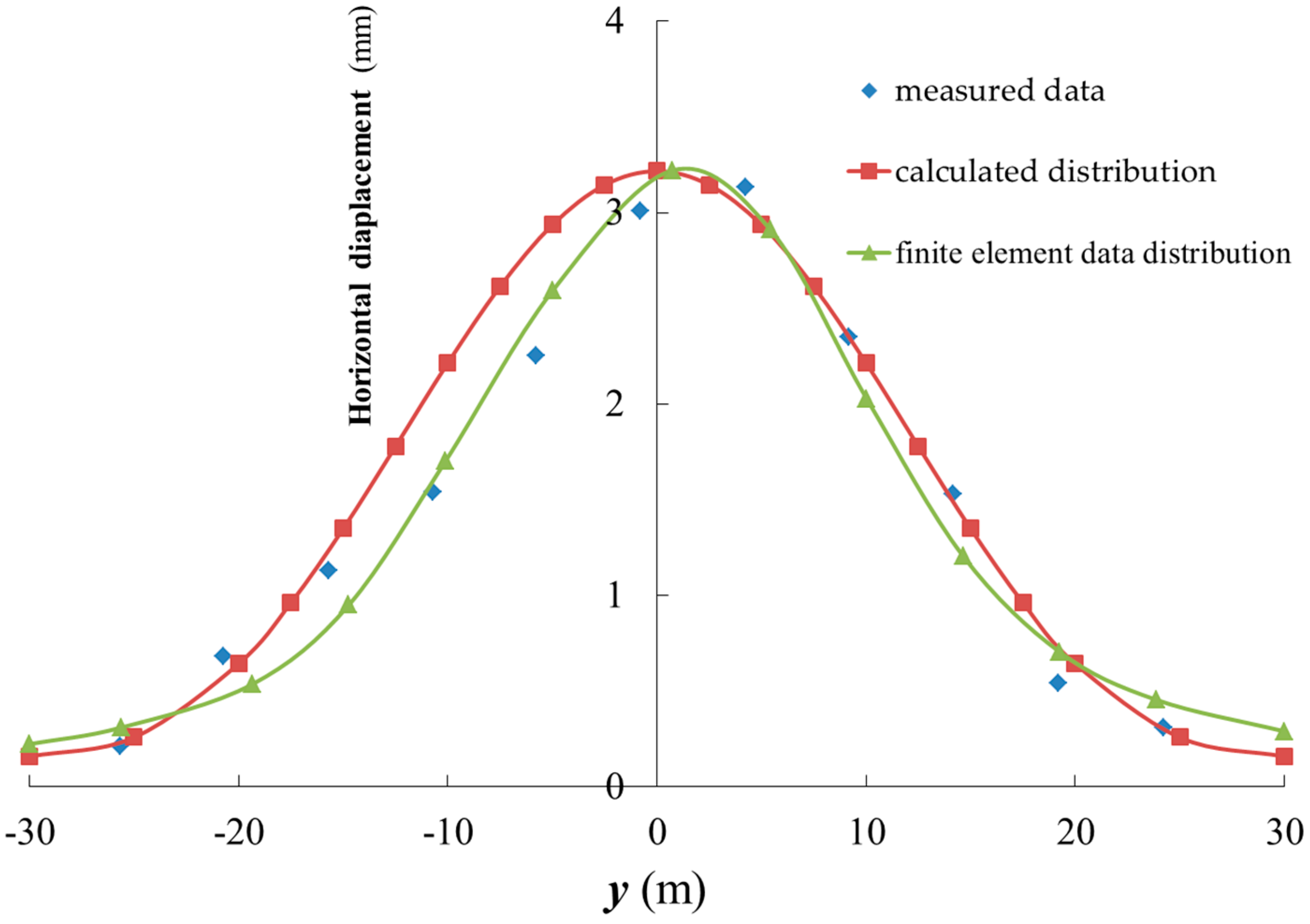
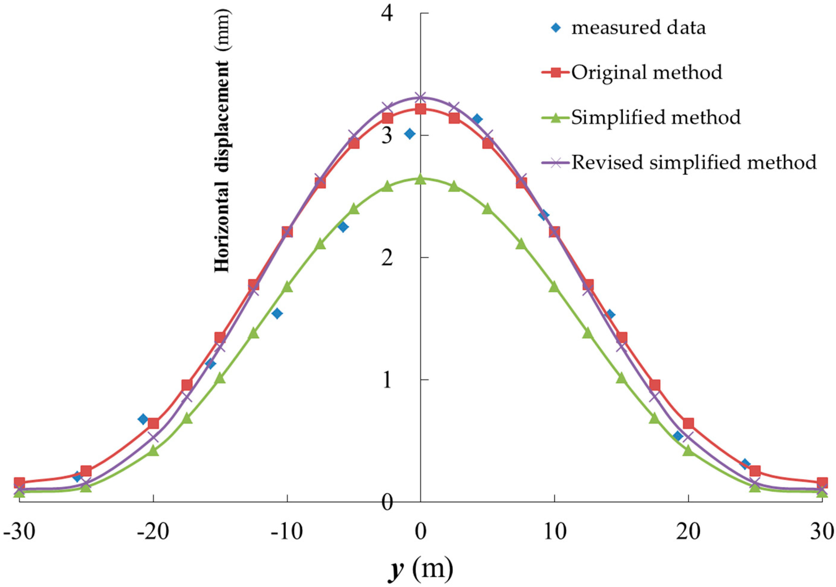
Figure 6 compares the compensated level of horizontal displacement of the tunnel calculated by the method developed herein with the measured data and the finite element data [2]. First, the curve of the horizontal displacement of the tunnel determined by the derived calculation method showed the characteristics of a large displacement in the middle and small displacements at both ends, which was just like the distribution of the measured data and the finite element data distribution; thus, the calculated distribution of the horizontal displacement of the tunnel well matched the measured data and the finite element data distribution. Second, the method proposed herein calculated the maximum horizontal displacement in the center of the tunnel at 3.22 mm, but the measured maximum horizontal displacement and the maximum horizontal displacement of the finite element method in the center of the tunnel were 3.01 and 3.2 mm, respectively. Hence, the measured maximum horizontal displacement and the maximum horizontal displacement of the finite element method of the tunnel were slightly smaller than the theoretically calculated value; however, the difference was negligible and satisfied the calculation accuracy requirements. Third, the range of the influence of grouting on rectification of the horizontal displacement of the tunnel calculated by the method developed in this paper was roughly the same as that reflected by the measured data; both presented an influence range of −30 to 30 m.
In summary, the results of the developed method were in good agreement with the measured data, which proves that the method derived in this work is reliable. Moreover, the proposed method has a certain degree of accuracy in calculating the correction of the horizontal displacement of existing tunnels caused by grouting. In order to accurately rectify the horizontal deformation of a tunnel, the grouting distance, the grouting depth, and the grouting volume should be designed and controlled in advance. Moreover, this method can help verify whether the impact of these parameters is reasonable and thus can be a reliable guide of actual engineering design. The parameters can be adjusted through repeated substitutions and calculations.

3.2.2. Accuracy Analysis of the Simplified Method

The horizontal additional stress caused by grouting includes σ x 1 2 (Equation (7)) and σ x 3 (Equation (8)). The calculation of the additional stress σ x 3 requires a more complex and highly time-consuming code in MATLAB®, which seriously affects the application and promotion of this method. Therefore, a simplified calculation of the compensated level of horizontal displacement of the tunnel without considering σ x 3 was performed. The comparison was also made between the results obtained by the simplified calculation and the original method.
Figure 7 compares the compensated level of horizontal displacement of the tunnel calculated by the original calculation method with that estimated by the simplified method. First, the distribution of the horizontal displacement of the tunnel estimated by the simplified method was similar to the one calculated by the original method; both represented a normal distribution and a basically similar influence range. Second, the whole distribution of the horizontal displacement of the tunnel estimated by the simplified method was below the one calculated by the original method, that is, the simplified method estimated a smaller horizontal displacement. The maximum difference between the horizontal displacement of the tunnel predicted by the two methods occurred at y = 0, that is, in the center of the tunnel. The simplified method estimated the maximum horizontal displacement in the center of the tunnel at 2.65 mm, which was 82.3% of that calculated by the original method. Third, comparing the distributions in the range of y = −10 m to y = 10 m revealed that the horizontal displacement values estimated by the simplified method were all about 79.8–82.3% of those calculated by the original method. Therefore, in the main influence zone, that is, in the range of y = −10 m to y = 10 m, the horizontal displacement estimated by the simplified method was about 80% of that determined by the original method. On the whole, the value estimated by the simplified method was smaller than that predicted by the original method.
In order to improve accuracy of the simplified method, its result was corrected by multiplying it with by a correction coefficient (q). A reference value of 1.25 was used for the correction coefficient based on the above study. As shown in Figure 7, the distribution of the horizontal displacement of the tunnel determined by the simplified method after correction was basically consistent with the distribution calculated by the original method. The maximum horizontal displacement in the center of the tunnel determined by the revised simplified method and the original method was 3.31 and 3.22 mm, respectively, leading to a difference of only 0.09 mm. Thus, the revised simplified method satisfies the calculation accuracy requirements and can balance calculation efficiency against result accuracy, so it is more suitable for promotion and application. In order to facilitate calculations, the revised simplified method is uniformly used for calculations and analysis in the following sections.

3.2.3. Comparison between Uniform Expansion Model and Nonuniform Expansion Model

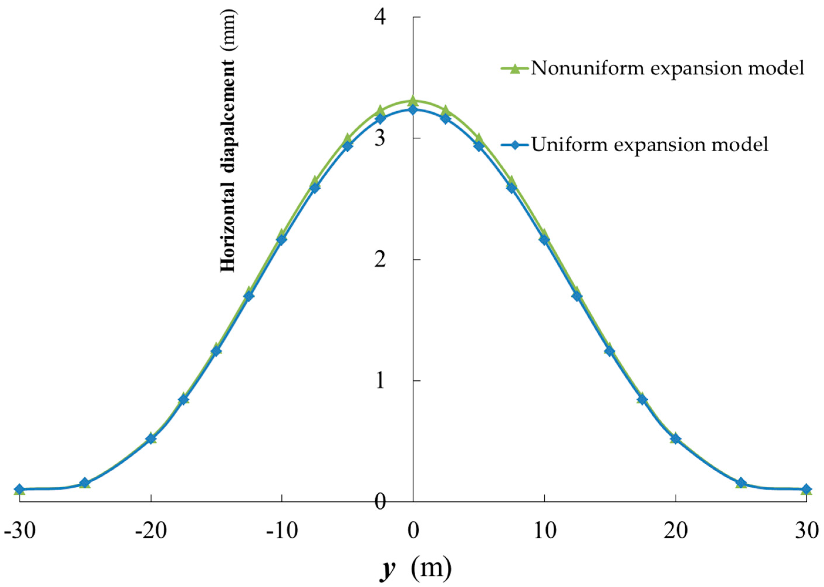
Aiming at the nonuniform expansion model of grouting proposed by Bai et al. [2], this study compared a nonuniform expansion model with the uniform expansion model. Figure 8 compares the compensated level of horizontal displacement of the tunnel calculated by the two expansion models. It is obvious that the distributions of horizontal displacement of the tunnel determined by the two models basically coincide. The maximum horizontal displacement in the center of the tunnel calculated by the nonuniform and uniform expansion models were 3.31 and 3.24 mm, respectively, or a difference of only 0.07 mm. Therefore, the results of the two models were basically equal. Considering the simplicity of model construction and calculation, it is more convenient and faster to select a uniform expansion model for the calculations.

4. Analysis of Single-Factor Influence Law

According to Section 3.2.2 and Section 3.2.3, the uniform expansion model and the revised simplified method are used for the calculations and analysis in this section.

4.1. Influence of Grouting Volume on Compensated Level of Horizontal Displacement of the Tunnel

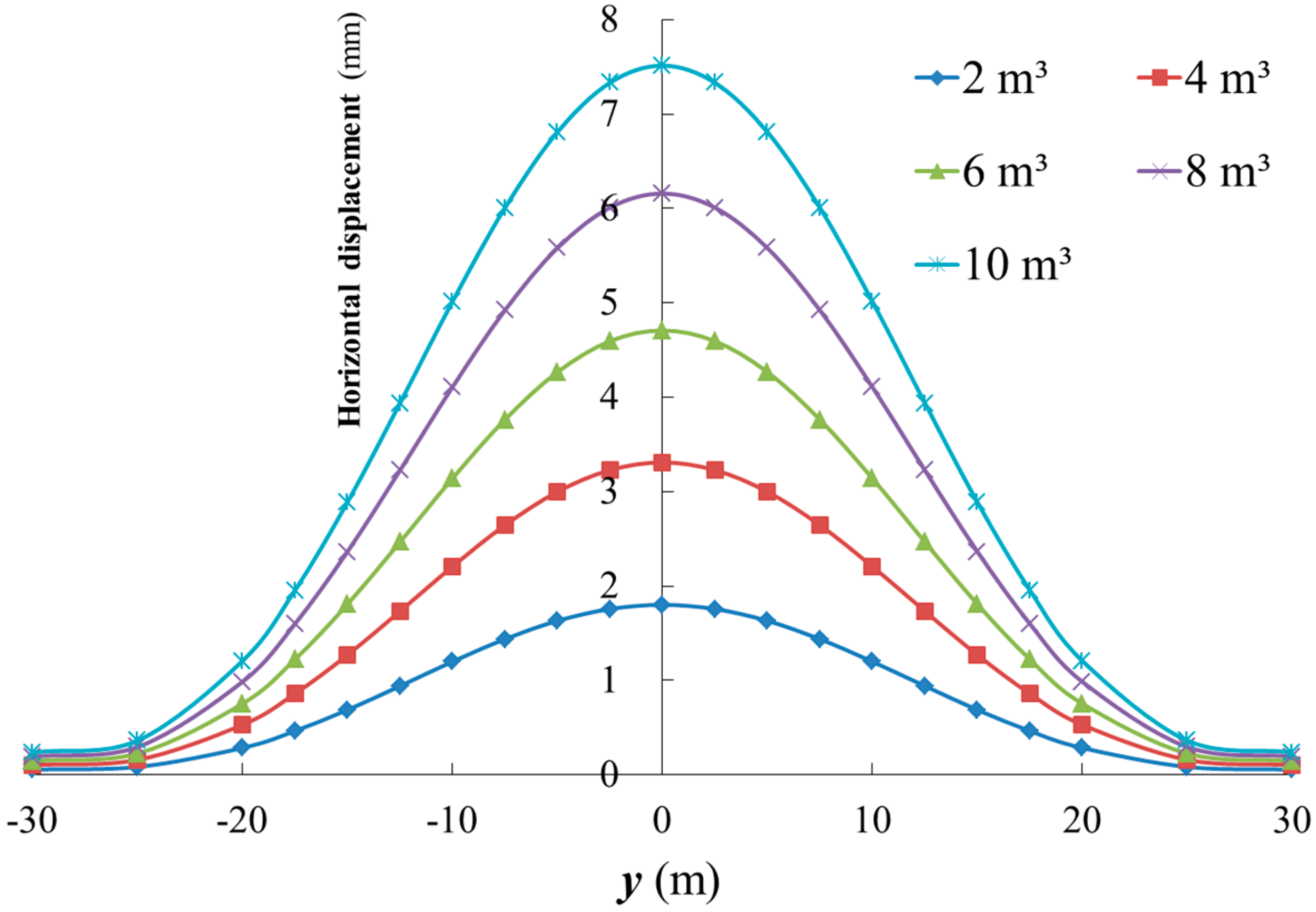
The example in Section 3.1 was considered as the standard operating condition, and the grouting volume of a single sleeve valve pipe was set at 2, 4, 6, 8, and 10 m3; the other parameters remained unchanged.
Figure 9 delineates the influence of different volumes of grouting on the compensated level of horizontal displacement of the tunnel. First, the horizontal displacement of the tunnel followed a normal distribution under different grouting conditions. Second, as the amount of grouting increased, the horizontal displacement of the tunnel gradually increased. At a grouting volume of 2, 4, 6, 8, and 10 m3, the maximum horizontal displacement in the center of the tunnel was 1.80, 3.31, 4.71, 6.16, and 7.51 mm, respectively. Third, as the amount of grouting increased, the affected area of the tunnel remained basically unchanged. The influence zone was chiefly concentrated in the range of y = –25 m to y = 25 m.
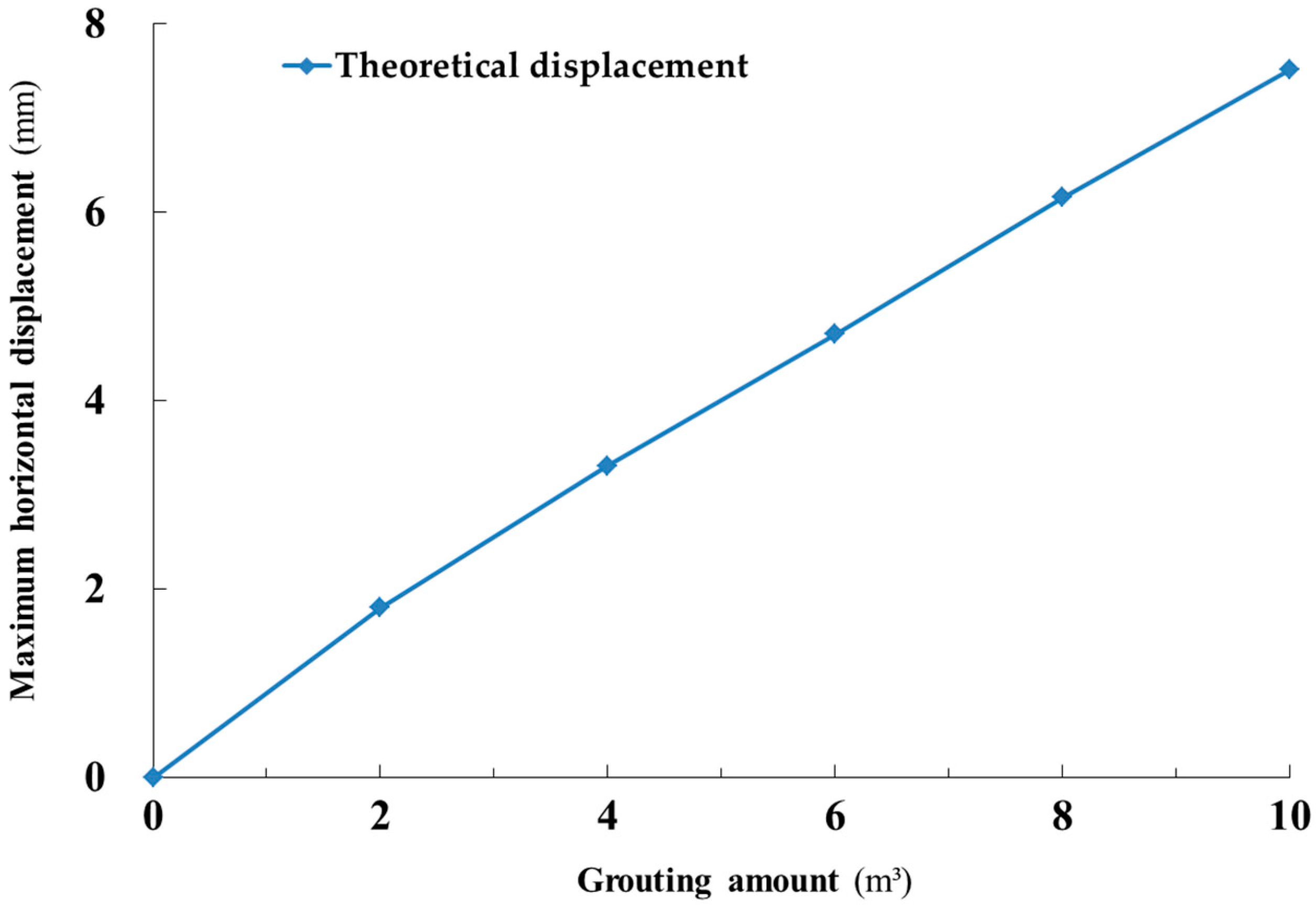
Figure 10 plots the relationship between the volume of grouting and the maximum horizontal displacement of the tunnel. As the grouting volume increased, although the maximum horizontal displacement of the tunnel slowly increased, the increasing trend gradually slowed down. This demonstrates that, in actual engineering, the amount of grouting can be increased to improve the corrective effect of grouting on the horizontal displacement of a tunnel. However, the volume of grouting should be controlled reasonably and should not be too large; indeed, an excessive volume of grouting has little effect on improving the grouting corrective effect. In addition, these findings are similar to the research results of Bai Rubing et al. [2], which further proves the accuracy of the theoretical calculation method developed herein.

4.2. Influence of Grouting Distance on Compensated Level of Horizontal Displacement of the Tunnel

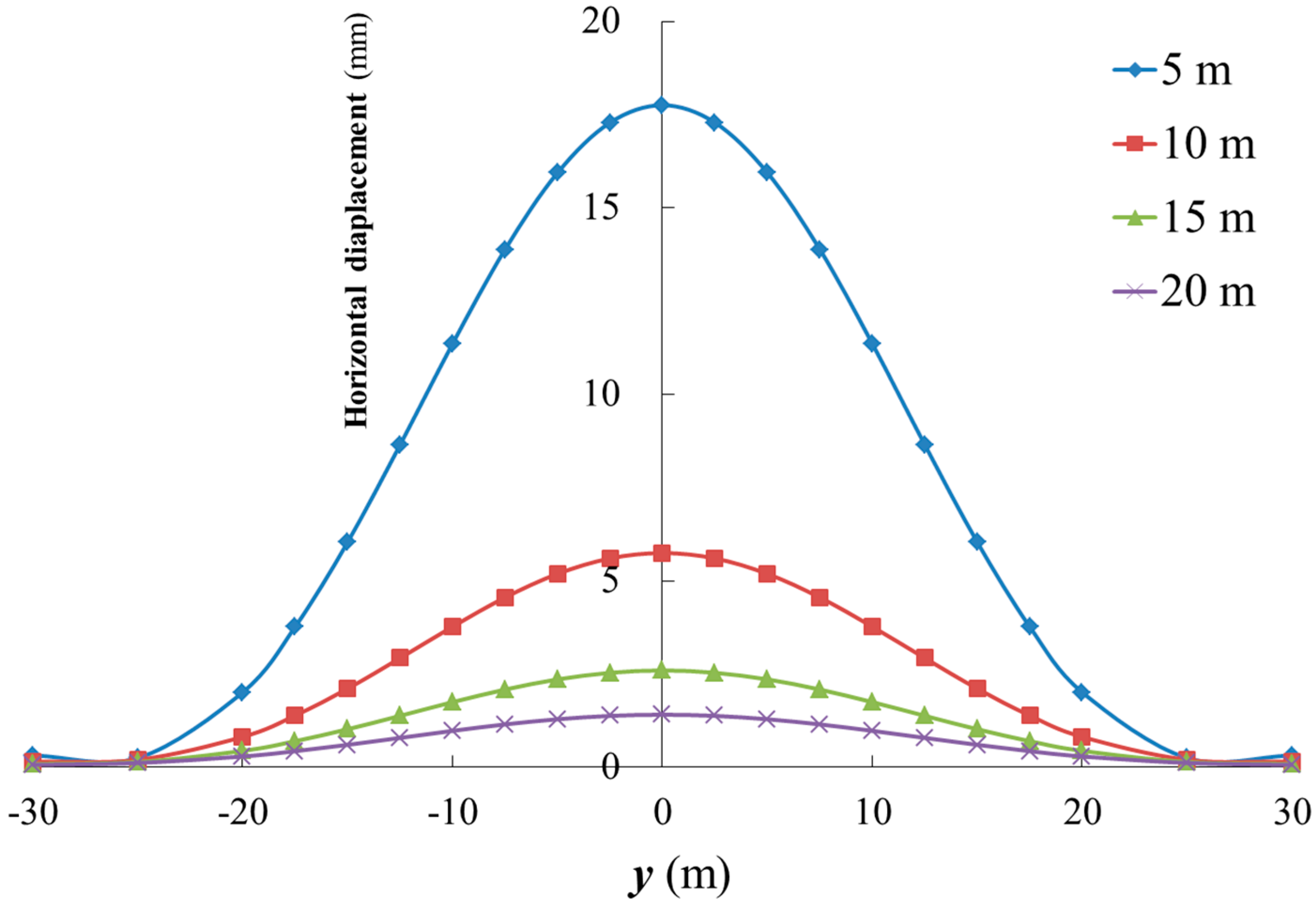
The example in Section 3.1 was considered as the standard operating condition, and the grouting distance was set at 5, 10, 15, and 20 m; the other parameters remained unchanged.
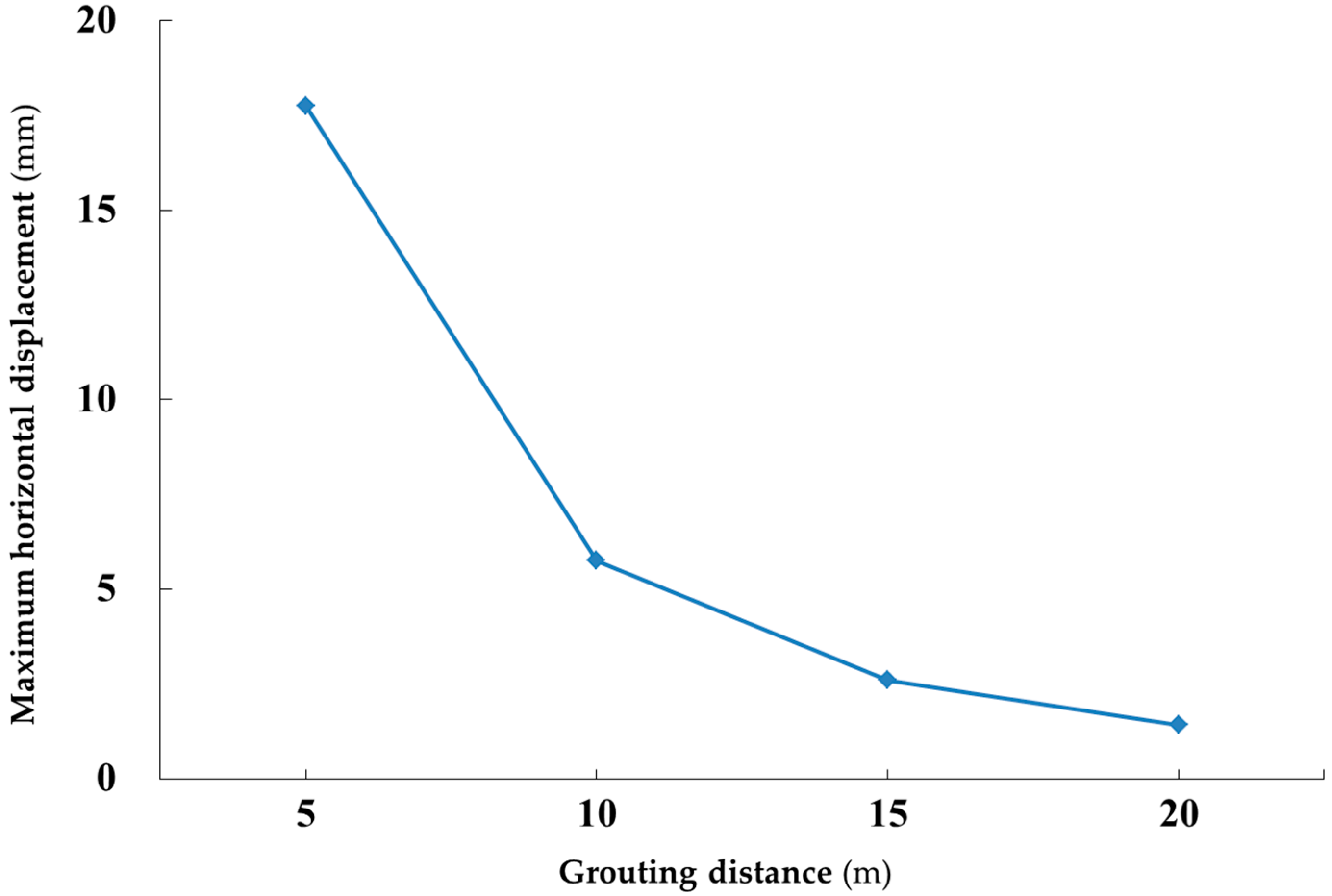
Figure 11 depicts the influence of the grouting distance on the compensated level of horizontal displacement of the tunnel, and Figure 12 delineates the relationship between the grouting distance and the maximum horizontal displacement of the tunnel. First, the variation of the grouting distance had a greater impact on the horizontal displacement of the tunnel. Second, as the grouting distance increased, the horizontal displacement of the tunnel gradually decreased. Indeed, at a grouting distance of 5, 10, 15, and 20 m, the maximum horizontal displacement in the center of the tunnel was 17.8, 5.75, 2.6, and 1.4 mm, respectively. Third, as the grouting distance increased, the maximum horizontal displacement of the tunnel gradually decreased, and then the downward trend slowly plateaued, which confirms that small changes in the grouting distance have a greater impact on the amount of correction of horizontal displacement of the tunnel when the grouting point is closer to the tunnel. Therefore, it is necessary to strictly control the grouting distance during grouting of a tunnel.

4.3. Influence of Grouting Depth on Compensated Level of Horizontal Displacement of the Tunnel

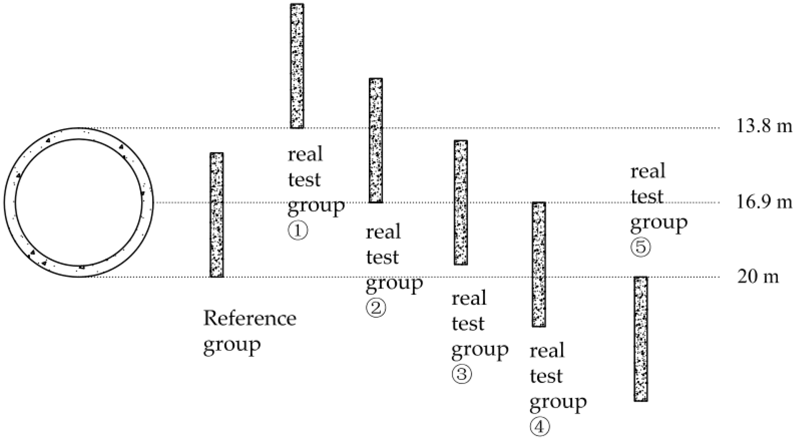
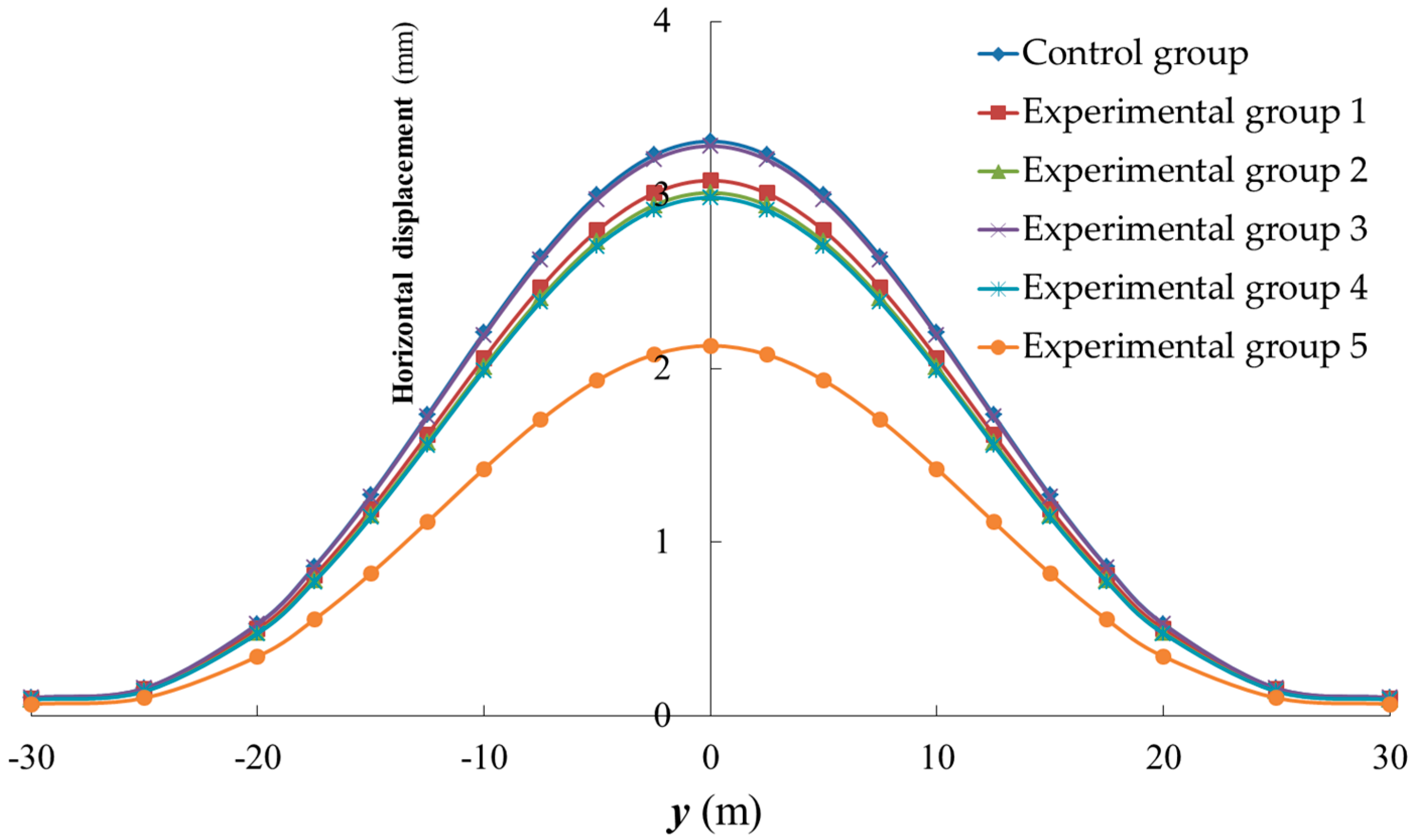
The example in Section 3.1 was considered as the standard operating condition. As shown in Figure 13, the length of the grouting section was kept unchanged at 5 m, and the depth of the grouting section was moved up and down. We considered a grouting depth of 15–20 m as the reference group, a grouting depth of 8.8–13.8 m as experimental group 1, a grouting depth of 11.9–16.9 m as experimental group 2, a grouting depth of 14.4–19.4 m as experimental group 3, a grouting depth of 16.9–21.9 m as experimental group 4, and a grouting depth of 20–25 m as experimental group 5. Then, the compensated level of horizontal displacement of the tunnel at each depth of the grouting section was calculated and compared.
Figure 14 shows the influence of the grouting depth on the compensated level of horizontal displacement of the tunnel. First, varying the grouting depth affected the horizontal displacement of the tunnel. The maximum horizontal displacement in the center of the tunnel of the control group and experimental groups 1–5 were 3.31, 3.08, 3.01, 3.28, 2.98, and 2.13 mm, respectively. Second, the grouting corrective effect of the control group was more significant than that of the experimental groups. The grouting depth scheme used in the engineering case in Section 3.1 was optimal. The buried depth of the grouting section of the control group was 15–20 m, which indicated that the lower end of the grouting section and the lower end of the tunnel were equal in depth.
In an actual project, at a fixed grouting length, grouting has the greatest effect when the buried depth (h2) of the lower end of the grouting section is equal to the depth of the lower end of the tunnel. This scheme can be used in the design process during construction to improve the efficiency of rectification by grouting.

5. Conclusions

From the findings of the current work, the following conclusions can be drawn:
  • The theoretical method developed in this work can calculate the compensation for rectifying the horizontal displacement of existing tunnels by grouting. It can also be used to determine the amount of horizontal displacement of tunnels corrected by grouting. The reliability of the method was verified by comparing the calculated results with actual engineering data. The nonuniform expansion model and the uniform expansion model function similarly in simulating the compensation for rectifying the horizontal displacement of tunnels by grouting. Moreover, both the original method and the revised simplified method proposed herein can properly calculate the horizontal displacement of existing tunnels caused by grouting. The revised simplified method has higher computational efficiency and thus is more suitable for promotion and application.
  • The variation of the grouting volume and the grouting distance in a small range has a more significant impact on rectification of the horizontal displacement of existing tunnels; beyond a certain range, the impact of the grouting volume and the grouting distance lessens. At a constant length of grouting section, setting the bottom of the grouting section at the same depth as the lower end of the tunnel maximizes the effect of grouting correction.
  • The method proposed herein can help guide actual construction in two ways. First, by substituting the relevant parameters of grouting into this model, the maximum horizontal displacement of the tunnel and the influence range of grouting can be calculated; thus, the results can determine whether the grouting scheme is appropriate. Second, the impact of grouting on rectification of the horizontal displacement of the tunnel can be adjusted by tuning the grouting parameters.
  • Finally, a single-factor analysis of the grouting volume, the grouting distance, and the grouting depth was conducted, which resulted in an understanding of the influence law of these parameters and some conclusive suggestions that are of great significance in guiding actual construction projects.
The current work simplified the influence of sleeve valve pipe grouting on the volume expansion of the grouting area; moreover, it took into account neither the variations in mechanical properties of the surrounding soil that may be caused by grouting, nor the volume expansion of the grout slurry over time. This study chiefly focused on analyzing the maximum corrective effect of grouting on the horizontal displacement of an existing tunnel. Therefore, herein, we assumed that the grouting efficiency was equal to one, i.e., ξinj = 1. In a follow-up research, variation in the grouting efficiency and in the corrective effect of grouting with time will be examined. In addition, the reference value of the correction coefficient (q) was obtained by inverse calculation based on measured data. In order to define ranges of the correction coefficient under different conditions, collation and inverse calculation of more similar project data need to be further developed. At present, due to the limited engineering data available, only a reference value of q =1.25 was given. The injection of a large amount of grout may cause the soil around the grouting area to change from an elastic state to a plastic state, which will affect calculation accuracy of the additional stress on the tunnel to a certain extent, although this effect is relatively small. On the other hand, considering the elastoplastic problem of soil will make the theoretical calculation method particularly complicated, which is not conducive to research and application of theoretical methods. Therefore, research on the influence of soil plasticization on the effect of grouting correction needs to be carried out in the future.

Author Contributions

Conceptualization, Y.Q.; methodology, Y.Q.; software, Y.Q.; validation, Y.Q., G.W., and F.F.; data curation, Y.Q.; writing—original draft preparation, Y.Q.; writing—original draft preparation, Y.Q., J.Z., and F.F. All authors have read and agreed to the published version of the manuscript.

Funding

This research was supported by the National Natural Science Foundation of China (Grant No. 51778576).

Data Availability Statement

Data is contained within the article or supplementary material.

Acknowledgments

We are grateful to other members of our research team (Zhang, X.H. and Wang, X.) for their technical support.

Conflicts of Interest

The authors declare no conflict of interest.

References

  1. Liu, G.; Jian-bo, L.; Xiong-wu, C. Research on the rectifying technology and automatic monitoring of shield tunnel operation in metro. Highw. Automot. Appl. 2018, 4, 150–154, 158. [Google Scholar]
  2. Ru-bing, B.; Gang, Z.; Yu, D.; Yi-ming, D.; Xue-song, C. Experimental study and numerical analysis of tunnel deformation control by compensation grouting. China Harb. Eng. 2018, 38, 24–28, 55. [Google Scholar]
  3. Wang, R.L.; Chen, Y.; Ren, J. Application of compensation grouting in the existing tunnels’repair. Under Ground Eng. Tunn. 2013, 51–57. [Google Scholar]
  4. Min, Z.; Xiao-Nan, G.; Xiang, G.; Shi-Ming, L.; Jia-Jia, Y. Model tests of correction of displaced shield tunnel using grouting technique. J. Railw. Sci. Eng. 2020, 17, 660–667. [Google Scholar]
  5. Zhang, D.M.; Zou, W.B.; Yan, J.Y. Effective control of large transverse deformation of shield tunnels using grouting in soft deposits. Chin. J. Geotech. Eng. 2014, 36, 2203–2212. [Google Scholar]
  6. Au, S.K.A.; Soga, K.; Jafari, M.R.; Bolton, M.D.; Komiya, K. Factors affecting long-term efficiency of compensation grouting in clays. J. Geotech. Geoenviron. Eng. 2003, 129, 254–262. [Google Scholar] [CrossRef]
  7. Min, Z.; Jun-Jun, L.; Wen-Quan, Q. Prediction and simplified model of uplift displacement by grouting. J. Taiyuan Univ. Technol. 2015, 46, 298–302. [Google Scholar]
  8. Li-Xin, L.; Wu-Li, T.; Jin-Feng, Z. Study on grouting uplift displacement prediction using stochastic medium theory. J. Railw. Sci. Eng. 2013, 10, 47–51. [Google Scholar]
  9. Sagaseta, C. Analysis of undrained soil deformation due to ground loss. Geotechnique 1987, 37, 301–320. [Google Scholar] [CrossRef]
  10. Tao, W.; Ri-Qing, X.; Jing-Jing, Q.; Hao, L. Additional stress field of surrounding soil due to shield tunneling. J. Zhejiang Univ. (Eng. Sci.) 2008, 42, 2009–2014. [Google Scholar]
  11. Ru-Bing, B. Study on Grouting Control of Influence of Foundation Pit Construction on Deformation of Adjacent Tunnels. Ph.D. Thesis, Tianjin University, Tianjin, China, 2018. [Google Scholar]
  12. Schweiger, H.F.; Kummerer, C.; Otterbein, R.; Falk, E. Numerical modelling of settlement COMPENSATION by means of fracture grouting. J. Jpn. Geotech. Soc. Soils Found. 2004, 44, 71–86. [Google Scholar] [CrossRef] [Green Version]
  13. Komiya, K.; Soga, K.; Akagi, H.; Jafari, M.R.; Bolton, M.D. Soil consolidation associated with grouting during shield tunneling in soft clayed ground. Geotechnique 2001, 51, 835–846. [Google Scholar] [CrossRef]
  14. Gollegger, J. Numerical and Analytical Studies of the Effects of Compensation Grouting. Ph.D. Thesis, Graz University of Technology, Graz, Austria, 2001. [Google Scholar]
  15. Xin-Liang, J.; Zhi-Min, Z. Application of image method in calculating tunneling-induced soil displacement. J. Harbin Inst. Technol. 2005, 37, 801–803. [Google Scholar]
  16. Gang, W.; Yong-Jie, Q.; Hua-Jun, W. Calculation of rotation and segment ring dislocation deformation caused by surcharge in shield tunnels. Tunn. Constr. 2019, 39, 1781–1789. [Google Scholar]
  17. Gang, W.; Xin-Hai, Z. Calculation of rotation and shearing dislocation deformation of underlying shield tunnels due to foundation pit excavation. J. Cent. South Univ. (Sci. Technol.) 2019, 50, 2273–2284. [Google Scholar]
  18. Qi, Y.; Wei, G.; Xie, Y. Method of Calculating the Vertical Displacement and Additional Stress of Existing Tunnels under the Influence of Grouting Rings of New Tunnels. Symmetry 2020, 12, 1623. [Google Scholar] [CrossRef]
  19. Shen, S.L.; Wu, H.N.; Cui, Y.J.; Yin, Z.Y. Long-term settlement behavior of metro tunnels in the soft deposits of Shanghai. Tunn. Undergr. Space Technol. 2014, 40, 309–323. [Google Scholar] [CrossRef]
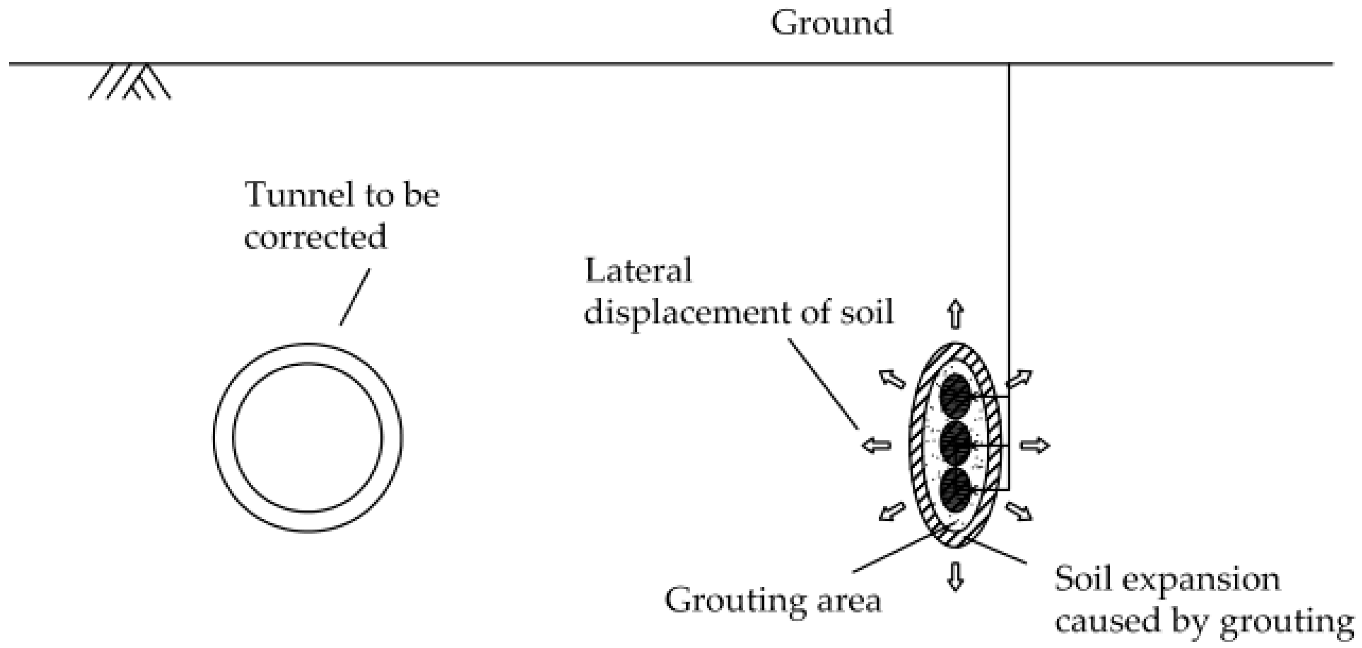
Figure 1. A schematic diagram of the corrective action of grouting.
Applsci 11 00040 g001
Figure 2. The mechanical calculation model.
Applsci 11 00040 g002
Figure 3. The model of uniform expansion of the grouting area.
Applsci 11 00040 g003
Figure 4. (a) The nonuniform expansion model of grouting; (b) the nonuniform expansion model of grouting used in the finite element method.
Applsci 11 00040 g004
Figure 5. Layout of rectification of tunnel displacement by the sleeve valve pipe technique: (a) front view; (b) floor plan.
Applsci 11 00040 g005
Figure 6. Comparison of the compensated level of horizontal displacement of the tunnel calculated by the proposed method with that by the measured data.
Applsci 11 00040 g006
Figure 7. Comparison of the compensated level of horizontal displacement of the tunnel calculated by the original method with that estimated by the simplified method.
Applsci 11 00040 g007
Figure 8. Comparison of the compensated level of horizontal displacement of the tunnel calculated by the nonuniform expansion model with that determined by the uniform expansion model.
Applsci 11 00040 g008
Figure 9. The influence of different volumes of grouting on the compensated level of horizontal displacement of the tunnel.
Applsci 11 00040 g009
Figure 10. The relationship between the volume of grouting and the maximum horizontal displacement of the tunnel.
Applsci 11 00040 g010
Figure 11. The influence of the grouting distance on the compensated level of horizontal displacement of the tunnel.
Applsci 11 00040 g011
Figure 12. The relationship between the grouting distance and the maximum horizontal displacement of the tunnel.
Applsci 11 00040 g012
Figure 13. Comparison of different depths of the grouting section.
Applsci 11 00040 g013
Figure 14. The influence of the grouting depth on the compensated level of horizontal displacement of the tunnel.
Applsci 11 00040 g014
Publisher’s Note: MDPI stays neutral with regard to jurisdictional claims in published maps and institutional affiliations.