Abstract
The creation of modern machines and improvement of existing designs of rock cutting bodies of combines is constrained by the lack of experimental studies of the process of separation of successive elementary cleavages during the potash ore cutting with cutters of winning machines. The potential of the cross cutting pattern of potash ore is shown, since the formation of zones of localization of weakening and induced fractures on the surface of layer-by-layer cutting face determines the separation of the elementary cleavages with stable geometric parameters. The verification of the conclusions obtained theoretically was carried out during laboratory tastings on a specially designed bench. The research procedure provided for comparative tests of the potash block ore cutting, staggered and cross cuttings. It has been proven that the use of the cross pattern for set cutting parameters makes it possible to reduce the specific energy costs of the cutting of potash mass, to reduce the average load on the cutter, to reduce the root-mean-square deviation, and to reduce the number of fractions that are hard to enrich in the crushing products, compared to the traditional staggered cutting pattern.
1. Introduction
The problem of increasing the efficiency of the machine mining of potash and magnesium ores by reducing the specific energy costs for the potash ore cutting with the cutters of mining combines and by increasing the number of fractions that are easily enriched in the ore is still very important for the enterprises of the potash industry in Russia [1]. The solution of this problem is possible with balanced contribution to the development of new and improvement of existing designs of rock cutting elements of mining combines used in the extraction of potash and magnesium ores [2,3].
Nowadays, local “Ural” heading-and-winning machines manufactured at the Kopeysk Machine-Building Plant (Kopeysk, Russia) are the most widely used ones in the potash mines of Russia and the CIS countries. However, it is worth noting that the design of these machines has not been fundamentally changed for more than 40 years [4].
The creation of modern machines equipped with operating bodies of up-to-date performance standards is constrained by the lack of research into the process of separation of successive elementary cleavages during the potash ore cutting with the cutters of winning machines [5].
2. Theoretical Studies of the Process of Potash Ore Cutting by Cross Cuttings
One of the advantages of the planetary-disk operating bodies is the creation of a grid of intersecting cuttings on the surface of the rock chips [6,7]. There are scientific studies of employees of Perm National Research Polytechnic University (PNRPU), Karaganda Research and Development Coal Institute (KRDCI), Moscow Mining Institute (MMI) and Giprouglemash, where the results of researches of the cross cutting pattern of potash ore blocks can be found [8,9,10,11,12,13].
Each next layer of the mass is cut in such manner that these cuttings intersect with the cuttings of the previous layer at a certain angle when the cross-cutting pattern is implemented. The layer that is destroyed by the cutters installed on one disk of the special planetary-disk element of the heading-and-winning machine is called operating layer of the rock mass [14,15].
The theoretical basics of the rock-breaking mechanism of potash ore by cross cuttings is going to be described below (Figure 1). The implemented rock cutting element is a cutter with a rectangular edge and a flat front face (as the most efficient for cross-cutting) [16].
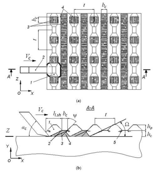
Figure 1.
Pattern of the separation of successive elementary cleavages of the potash mass during the destruction by cross cuttings: (a)—cutting face by cross cuttings: 1—large elementary cleavage; 2—cutter; 3—intersecting cuttings; 4—zones of concentration of fractures; (b)—pattern of separation of elementary cleavages of potash mass during the cutter’s movement across the cuttings of the operated layer: 1—large elementary cleavage; 2, 3, 4—small intermediate cleavages; 5—zones of concentration of stresses and fractures.
The cutter (cutting angle αc, cutting edge width bc) moves at the speed of Vc across the cuttings of the operated layer of the mass in the cutting plane Z. The cutter is deepened in relation to the cuttings of the operated layer by the value hc. The total thickness of the cleavage h is determined be the Equation (1):
where hc—the value of the deepening of the intersecting cuttings in relation to the cutting of the operated layer, mm; hp—height of a protrusion, mm.
h = hc + hp,
The cuttings of each layer form intersecting zones of concentration of stresses and localization of man-made fractures on the face surface. The practical location of the zones of induced fractures is determined by the value of the rational cutting step tr.s. of the cross and co-directional cuttings.
The cutter penetrates into the potash mass during the rock-breaking step, while crushing and plastic deformation of a certain volume of ore is realized. The zone of stressed state is formed in the pre-cutter space. The implementation of traditional cutting patterns [17] is characterized by the formation of large cleavages, which are obtained during the creation and development of main fractures in the zone of contact of the front edge of the cutter with the potash mass. A counter-propagation of the transverse shear fractures existing in the mass («starting» fractures), concentrated along the perimeter of the base of the formed protrusion, is occurring during the potash ore cutting by cross cuttings, provided that the cutting step is less than or equal to the rational cross cutting step (t ≤ tr.s.). The formation of the fracture surfaces of elementary cleavages through the development of the induced fractures existing in the mass determines a decrease in the forces required for the cleavage. Moreover, it decreases the volume of the bulb of pressure (consists of the fine particles of crushed rocks) and the zone of inelastic deformation of the ore [18].
Therefore, practical shaping of the cutting face using cross cutting pattern with the rational step tr.s. determines a decrease of the specific energy costs of the rock-breaking mechanism of potash ore, a lowering of the output of the small dust-like fractions, and an increase of the number of large formed cleavages in the broken ore.
If the problem is solved approximately, the equation for determining the rational cutting step tr.s., when the cross-cutting pattern is implemented, is the following:
where ll.sh—length of a large elementary cleavage of a stable shape, mm; ω—angle between a cutting plane and lower fracturing surface of a large elementary cleavage with the length ll.sh, degrees.
Regular protrusions of a stable shape are formed between co-directional cuttings at t ≤ tr.s.. Displacement of the cutter by a cutting step t entails the separation of one large cleavage from the mass when the cross cutting pattern is implemented (Figure 1, position 1). The frequency of occurrences of large cleavages f1 (Hz) at a constant cutting speed Vc is determined by Equation (3):
where T1—time of displacement of the cutter by cutting step t, s.
The destruction of the mass sections located between the regular protrusions formed by the co-directional cuttings is carried out by formation of intermediate cleavages (see Figure 1b, positions 2, 3, 4). The number of intermediate cleavages per one large cleavage is determined by the width of the edge bc of the cutter and the value of its deepening hc into the mass. The parameters of the intermediate cleavages are random. Their separation from the mass is followed by crushing and plastic deformation of the ore. The frequency of occurrences of the intermediate cleavages f2 (Hz) is determined by Equation (4):
where T2—time of occurrence of the small intermediate cleavages, s.
Verification of the results of the aforementioned theoretical studies can be done by conducting experimental studies on a laboratory bench where potash ore it cut with a single cutter [19,20,21].
3. Investigation of the Rock-Breaking Mechanism of Potash Ore with a Single Cutter
The employees of the Department of Mechanical Engineering of the Saint Petersburg Mining University designed and manufactured a bench (Figure 2) in order to experimentally study the rock-breaking mechanism of a potash mass with a single cutter [16,22].
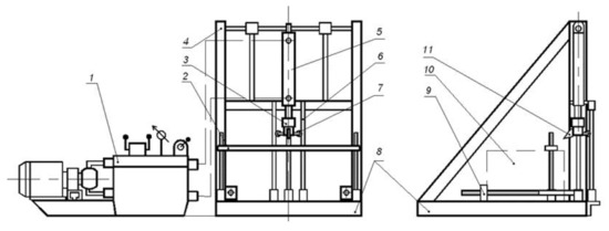
Figure 2.
Laboratory bench for potash ore cutting by cutting.
The bench includes a base 8 on which a welded frame 4 is located (connected by welded seams and jibs). Hydraulic double-sided power cylinder 5 connected to a measuring hydraulic cylinder 3, where a cutter 11 is located, is rigidly fixed on the frame 4. The supply of an actuating fluid (I-20A oil) in the cavities of the hydraulic cylinder 5 is carried out by a pumping station 1. A pressure indicator is connected to the measuring hydraulic cylinder 3 to measure the cutting force Pz on the cutter 11.
Three vertical guide rails 6, along which rollers 7 of the measuring hydraulic cylinder 3 can move, are provided in the design of the bench in order to ensure the rectilinear motion of the cutter 11. A potash ore block 10 is installed on the base 8 and fixed in a stationary position with clamps 2 and 9. The step and deepening of the cutting are set by moving the block 10 [16,22].
The bench hydraulic system (Figure 3) consists of two gear-type pumps 3 and 16 driven by a three-phase asynchronous motor 1 through a gearbox 2. The actuating fluid is supplied from an oil tank 12 into the cavities of the power hydraulic cylinder 13, the rod of which is connected to the measuring hydraulic cylinder 14 and the cutter 15. The piston diameter of the measuring hydraulic cylinder is 40 mm. The direction of movement of the cutter is determined by switching a spool 11, and the speed of the translational motion is controlled by a flow regulator 9.
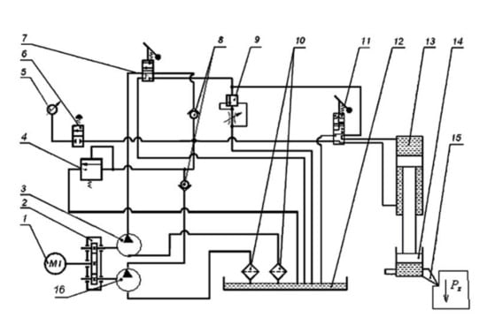
Figure 3.
Hydraulic system of the bench.
Expansion of the range of feed rate of the cutter 15 during the penetration into the destroyed block is possible through the operation of one or two gear-type pumps. The gear-type pump 16 is controlled by a spool 7. A safety valve 4 is provided in order to protect the system from overloads. The pressure is controlled by a pressure gauge 5 connected to the pressure pipe through a spool 6. Moreover, there are reverse-flow valves 8 and filters 10 for cleaning the actuating fluid in the hydraulic system. The general view of the bench is shown in Figure 4.
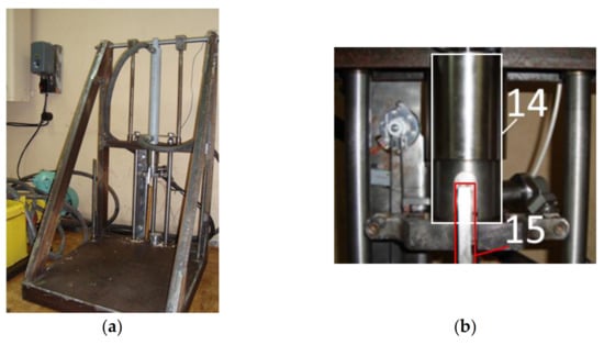
Figure 4.
General view of the bench (a) and (b) the measuring hydraulic cylinder 14 with the cutter 15, pressure and displacement indicators.
A pressure indicator is connected to the cylinder 14 (see Figure 3), where the pressure is proportional to the cutting force Pz. The feed rate of the cutter 15 is controlled by a displacement indicator—an encoder. The sampling rate of the indicators is 0.5 kHz. Data from the measuring indicators is recorded and converted by a multi-channel AD/DA encoder and processed on a personal computer by specialized software using well-known methods of mathematical statistics, correlation, and spectral analysis.
The parameters of the samples taken for the experimental studies:
- -
- shape: cuboid with dimensions 300 × 300 × 600 mm;
- -
- origin: Uralkali PJSC, Verkhnekamskoye deposit of potassium and magnesium salts, Krasny-II seam;
- -
- cutting resistance Ac = 400…430 N/mm [23].
The rock cutting tool is a cutter with a flat front face and a rectangular cutting edge. The width of the cutting edge is bc = 10 mm, cutting angle is αc = 50°, clearance angle is βc = 5°. The hydraulic drive of the cutter provides an average speed Vc = 0.1 m/s. Types of cuttings: from a leveled surface, staggered and cross.
The ore separated from the block was collected using dust exhaustion, and then it was weighed and screened in order to determine the grain-size distribution. Large ore cleavages were selected manually. Specific energy costs of the rock-breaking process were calculated using Equation (5):
where Hw—specific energy costs of the breaking process of the block of potash ore with a single cutter, kW∙h/t; Pzc—average cutting force on a single cutter, N; γk—density of the potash ore in the block, t/m3; G—mass of the ore separated from the block (mass of the rock chips), kg.
The values of the average cutting force on a single cutter and its root-mean-square (standard) deviation were calculated using the Equations (6) and (7):
where Pzi—instantaneous value of the cutting force on a single cutter, N; n—number of sampling intervals; σp—root-mean-square (standard) deviation of the cutting force, N.
4. The Results of the Experimental Studies
Potash ore cutting with a single cutter is a complex multifactorial cycle process of alternation of phases of contact crushing and the formation of large cleavages. The separation of each large cleavage from the mass is followed by the formation of the bulb of pressure and inelastic deformation of the potash ore. The cuttings products contain both large elements and dust particles.
Propulsion parameters of the rock-breaking mechanism of the samples by cuttings from a leveled surface were analyzed using three oscilloscope waveforms (Figure 5a) obtained under equal conditions (h = 10 mm, t/h > 7.2). The average value of the cutting force was Pzl = 2400 N, which made it possible to determine the cutting resistance Ac of the tested potash ore block:
where kb—influence coefficient of the width of the cutting edge. The value of the coefficient kb is determined empirically. It characterizes the difference between geometrical parameters of the cutter used in these studies and the parameters of the reference cutter, which is used to determine the cutting resistance Ac in the known approaches.
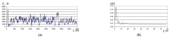
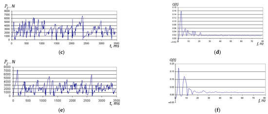
Figure 5.
Change in the cutting force Pz (a,c,e) and spectral density Q(t) of the cutting force (b,d,f) during the destruction of the samples with a single cutter: a,b—cuttings from a leveled surface; c,d—staggered cuttings; e,f—cross cuttings.
Comparison of the value of the cutting resistance Ac obtained experimentally with the known values determined by the employees of the VNII Galurgii sectoral research institute for sylvinite of the BKPRU-4 mine confirms the high reliability of the experimental results [23].
Spectral density allows assessing the frequency distribution of the cutting force. There is an isolated surge of the spectrum in the Figure 5b, at a frequency of 2 Hz, which characterizes the frequency of the formation of a large cleavage in the cutting.
The research procedure provides for the determination of the grain-size distribution of the rock-breaking mechanism of the potash ore by cutting from a leveled surface and for the calculation of the specific energy costs of the cutting process. The results of the screening of the ore separated from the block are presented in the Table 1.

Table 1.
Grain-size distribution of the potash ore separated from the sample during bench tests.
The value of the root-mean-square deviation of the cutting force during the potash ore cutting sample by the cutting from a leveled surface at h = 10 mm was σcl = 1045.8 N. Specific energy costs of the rock-breaking mechanism of the potash ore by cutting from a leveled surface is Hwl = 3.6 kW·h/m3, which corresponds with the results of the previously performed similar studies [11].
The study of the rock-breaking mechanism of potash ore was carried out according to a staggered pattern with a cutting step of t = 35 mm and a cutting depth in relation to the layer of previous cuttings hc = 5 mm (the total thickness of the cleavage was h = 10 mm). Reporting cuttings were made from the surface (pre-formed) typical for a staggered- cutting pattern. The parameters of the rock-breaking mechanism of the samples by staggered cuttings were analyzed using three oscilloscope waveforms obtained under equal conditions (see Figure 5c). The average value of the cutting force was Pzs = 2564.8 N, the specific energy costs of the rock-breaking mechanism of the potash mass by staggered cuttings was Hws = 1.72 kW·h/m3, which corresponds to the results obtained by the authors of the paper [10] during similar studies.
There is an isolated surge of the spectrum in the Figure 5d, at a frequency of 3 Hz, which characterizes the frequency of the formation of a large cleavage in the cutting. The value of the root-mean-square deviation of the cutting force during the potash ore cutting sample by the staggered cuttings at h = 10 mm was σcs = 1045.8 N.
The results of the analysis of grain-size distribution of the potash ore separated from the destroyed block by staggered cuttings (see Table 1) show that the implementation of a staggered cutting pattern allows mildly reducing the number of small fractions of “−0.25” size, which are hard to enrich, in the rock chips in comparison with the cutting from a leveled surface method (from 3.69% to 2.94%).
The study of the rock-breaking mechanism of potash ore was carried out according to a cross pattern with a cutting step of t = 35 mm and a cutting depth in relation to the layer of previous cuttings hc = 5 mm (the total thickness of the cleavage was h = 10 mm). Reporting cuttings were made from the surface (pre-formed) typical for a cross-cutting pattern.
Propulsion parameters of the rock-breaking mechanism of the samples by cross-cutting were analyzed using three oscilloscope waveforms (Figure 5d) obtained under equal conditions. The average value of the cutting force was Pzc = 1910 N, the root-mean-square deviation of the cutting force was σcc = 1045.8 N, the specific energy costs of the rock-breaking mechanism of the potash mass by cross-cutting was Hwc = 1.46 kW·h/m3.
There are isolated surges of the spectrum in the Figure 5f, at frequencies of 3 Hz and 8 Hz. The formation of large cleavages of a stable shape is happening at a frequency of 3 Hz, small intermediate cleavages are formed at a frequency of 8 Hz. The grain-size distribution of the destruction products of the ore block by cross-cutting is presented in Table 1. A summary of the load-bearing and energy characteristics of the process of potash ore cutting with a single cutter for each experiment is given in Table 2.
Table 2.
Load-bearing and energy characteristics of the process of potash ore cutting with a single cutter.
The relative error of the experimental data does not exceed 10%. Therefore, the decrease in specific energy costs of the cross-cutting process with the cutting parameters bc = 10 mm, h = 10 mm, t = 35 mm in comparison with the staggered pattern is:
where Hwc—specific energy costs of the rock-breaking mechanism of the sample by cross cutting, Hwc = 1.46 kW∙h/m3; Hws—specific energy costs of the rock-breaking mechanism of the sample by staggered cutting, Hws =1.72 kW∙h/m3.
The decrease in the average loads on the cutter when using the cross-cutting pattern compared to the staggered pattern is:
where Pzc—average cutting force when using the cross-cutting pattern for potash mass, Pzc = 1910 N; Pzs—average cutting force when using the staggered-cutting pattern for potash mass, Pzs = 2564.8 N.
The decrease in the root-mean-square deviation of loads on the cutter during the implementation of the cross-cutting pattern compared to the staggered pattern is:
where σcc—dispersion of loads on the cutter during the implementation of the cross-cutting pattern, σc.c.= 1093.2 N; σcs—dispersion of loads on the cutter during the implementation of the staggered cutting pattern, σcs = 1300.3 N.
The decrease in the number of fraction of «−0.25 size», which are hard to enrich, when the cross pattern is implemented in comparison with the staggered pattern is:
where M−0.25.c—mass content of the fractions, which are hard to enrich, when the cross-cutting method is implemented, M−0.25.c = 1.7%; M−0.25.s—mass content of the fractions, which are hard to enrich, when the staggered-cutting method is implemented, M−0.25.s = 2.94%.
The calculated frequencies of the formation of large stable and small intermediate cleavages, in accordance with Equations (3) and (4), are:
The calculated values of the frequencies are close to the values obtained experimentally (see Figure 5d), which amounted to 3 Hz and 8 Hz, respectively.
5. Conclusions
The results of theoretical and experimental studies of a promising cross-cutting pattern showed the following:
- Elementary cleavages developed during the potash ore mass cutting by cross-cutting are formed due to the propagation of the main transverse shear fractures, and not breaking off, which is characteristic of the formation of cleavages when the cuttings from a leveled surface or staggered cutting are implemented. These facts are responsible for the decrease in the force and energy parameters of the potash ore mass cutting when the cross-cutting pattern is implemented in comparison with traditional patterns.
- Formation of the intersecting areas of localization of induced fractures and concentration of stresses on the surface of potash mass causes the separation of large elementary shears of a stable shape, which determines the increase in the quality of the grain-size distribution of potash ore in the case of implementing the cross-cutting pattern compared to the staggered one [24].
- The implementation of the cross-cutting pattern compared to the staggered pattern with the set cutting parameters (cutting step t = 35 mm, the total thickness of the shear h = 10 mm, cutting depth in relation to the layer of previous cuttings hc = 5 mm, the width of the cutting edge bc = 10 mm) allows decreasing the specific energy costs of the potash ore mass cutting by 15%, decreasing the average loads on the cutter by 34%, decreasing the root-mean-square deviation of loads by 16%, and decreasing the number of fractions that are hard to enrich in the crushing products by 42%.
The obtained results make it possible to substantiate the rational parameters of planetary-disk operating bodies that destroy the potash mass by cross-cutting. The results of theoretical and experimental studies of the formation process of successive elementary cleavages that make up the cutting facilitate the search for implicit ways to increase the efficiency of potash ore machine mining, and provide for the creation of the heading-and-winning machines with up-to-date performance standards [5].
Author Contributions
Conceptualization, D.S.; methodology, D.S. and I.Z.; investigation, D.S. and I.Z.; formal analysis, D.S. and I.Z.; resources, D.S.; validation, D.S.; visualization, D.S. and I.Z.; writing—original draft preparation, D.S.; writing—review and editing, I.Z. All authors have read and agreed to the published version of the manuscript.
Funding
This research received no external funding.
Institutional Review Board Statement
Not applicable.
Informed Consent Statement
Not applicable.
Data Availability Statement
Data is contained within the article or supplementary material. The data presented in this study are available in «Shishlyannikov, D.I. Increasing the Efficiency of Separating Potash Ore from the Massif with Cutters of Mining Combines. Ph.D. Thesis, Engineering Sciences, Saint Petersburg Mining University, Saint Petersburg, Russia, 2012».
Conflicts of Interest
The authors declare no conflict of interest.
References
- Gabov, V.V.; Zadkov, D.A.; Kuzkin, A.Y.; Elikhin, A.S. Fractured-laminar structure of formations and methods of coal. Key Eng. Mater. 2020, 836, 90–96. [Google Scholar] [CrossRef]
- Ivanov, S.L.; Ivanova, P.V.; Kuvshinkin, S.Y. Promising model range career excavators operating time assessment in real operating conditions. J. Min. Inst. 2020, 242, 228–233. [Google Scholar] [CrossRef]
- Lavrenko, S.A.; Korolev, I.A. Analysis of cambrian clay cutting during Saint-Petersburg subway construction. Gorn. Zhurnal 2018, 1, 53–58. [Google Scholar] [CrossRef]
- Starkov, L.I.; Zemskov, A.N.; Kondrashev, P.I. Development of Mechanized Mining of Potash Ores; PGTU: Perm, Russia, 2008; p. 522. [Google Scholar]
- Urazbakhtin, R.Y.; Yungmeyster, D.A. The results of studies of the tunneling rescue complex for coal mines. IOP Conf. Ser. Mater. Sci. Eng. 2019, 560, 012130. [Google Scholar] [CrossRef]
- Chekmasov, N.V.; Nemtsev, V.A. Substantiation of the directions of improvement of road heading machines. PNIPU Bull. Geol. Oil Gas Min. 2005, 6, 238–239. [Google Scholar]
- Yang, Y.; Zhang, C.; Lin, M.; Chen, L. Research on rock-breaking mechanism of cross-cutting PDC bit. J. Petrol. Sci. Eng. 2018, 161, 657–666. [Google Scholar] [CrossRef]
- Lukin, D.G.; Yungmeister, D.A.; Yacheikin, A.I.; Isaev, A.I. Improvement of shield machine KT1-5.6M cutterhead operation. Gorn. Zhurnal 2018, 12, 73–77. [Google Scholar] [CrossRef]
- Polyakov, S.V.; Pushkarev, A.E. Parameters determining differences between geometric and mechanical properties of spiral elements in rope, affecting development of emergency situations. In Proceedings of the GFAC 2019, Saint Petersburg, Russia, 6–8 February 2019; pp. 270–273. [Google Scholar] [CrossRef]
- Solod, V.I.; Getopanov, V.N.; Rachek, V.M. Design and Construction of Mining Machines and Complex; Nedra: Moscow, Russia, 1982; p. 350. [Google Scholar]
- Starkov, L.I.; Kharlamova, N.A. Cross-cut pattern study. Min. J. Proc. High. Educ. Inst. 1997, 7–8, 74–76. [Google Scholar]
- Sveshnikov, I.A.; Mishnyaevskij, L.L. Study of the step bottom of hole in rotary drilling with carbide inserts bits. Sverkhtverdye Mater. 1992, 1, 51–56. [Google Scholar]
- Zhabin, A.B.; Polyakov, A.V.; Averin, E.A.; Linnik, Y.N.; Linnik, V.Y. Estimation of abrasiveness impact on the parameters of rock-cutting equipment. J. Min. Inst. 2019, 240, 621–627. [Google Scholar] [CrossRef]
- Lavrenko, S.A.; Yungmeister, D.A.; Igorevich, S.D.; Iusupov, G.A. Simulation of the process of destruction of the array of cambrian clays by cutters actuating device of sinking machinery in terms of OJSC «Metrostroy», St. Petersburg. Int. J. Appl. Eng. Res. 2015, 10, 16409–16417. [Google Scholar]
- Wu, D.P.; Yang, X.A.; He, Z.S.; Cao, L. Study on eccentric wear mechanism of pick-shaped cutter in soft and hard interbedded formation tunnel. Appl. Mech. Mater. 2014, 501–504, 1668–1671. [Google Scholar] [CrossRef]
- Shishlyannikov, D.I. Increasing the Efficiency of Separating Potash Ore from the Massif with Cutters of Mining Combines. Ph.D. Thesis, Engineering Sciences, Saint Petersburg Mining University, Saint Petersburg, Russia, 2012. [Google Scholar]
- Xuan, N.V.; Linh, N.; Gabov, V.V.; Lykov, Y.V. Relocation schemes of picks with cutting, coupling and group cuts on shearer cutting drums. IOP Conf. Ser. Earth Environ. Sci. 2019, 378, 012022. [Google Scholar] [CrossRef]
- Zhu, J.; Zhai, T.; Liao, Z.; Yang, S.; Liu, X.; Zhou, T. Low-amplitude wave propagation and attenuation through damaged rock and a classification scheme for rock fracturing degree. Rock Mech. Rock Eng. 2020, 53, 3983–4000. [Google Scholar] [CrossRef]
- Ji, Y.J.; Li, R.K. DEM simulation study of crosscutting speed for the cutting header. Appl. Mech. Mater. 2014, 470, 188–192. [Google Scholar] [CrossRef]
- Zhang, Z.; Zhang, K.; Dong, W.; Zhang, B. Study of rock-cutting process by disc cutters in mixed ground based on three-dimensional particle flow model. Rock Mech. Rock Eng. 2020, 53, 3485–3506. [Google Scholar] [CrossRef]
- Zhu, Q.-Z.; Shao, J.-F. A semi-empirical failure criterion for brittle rocks. Rock Mech. Rock Eng. 2020, 53, 4271–4277. [Google Scholar] [CrossRef]
- Zadkov, D.A.; Gabov, V.V.; Nguyen, K.L. Features of elementary burst formation during cutting coals and isotropic materials with reference cutting tool of mining machines. J. Min. Inst. 2019, 236, 153–161. [Google Scholar] [CrossRef]
- Heading-and-Cleaning Combines for the Extraction of Potash Ores. Selection of Destination Indicators and Calculation of Rock Destruction Parameters; VNIIG: Leningrad, Russia, 2008; p. 31. [Google Scholar]
- Lipnitsky, N.A.; Kuskova, Y.V. Complex approach to the development of potash, potassium-magnesium and salt deposits. E3S Web Conf. 2018, 41, 01005. [Google Scholar] [CrossRef]


Publisher’s Note: MDPI stays neutral with regard to jurisdictional claims in published maps and institutional affiliations. |
© 2021 by the authors. Licensee MDPI, Basel, Switzerland. This article is an open access article distributed under the terms and conditions of the Creative Commons Attribution (CC BY) license (http://creativecommons.org/licenses/by/4.0/).