Article

Adaptive Generalized Synchronization between Circuit and Computer Implementations of the Rössler System

Youth Research Institute, Saint Petersburg Electrotechnical University “LETI”, 197376 Saint Petersburg, Russia
*
Author to whom correspondence should be addressed.
Appl. Sci. 2021, 11(1), 81; https://doi.org/10.3390/app11010081
Submission received: 28 November 2020 / Revised: 18 December 2020 / Accepted: 22 December 2020 / Published: 24 December 2020
(This article belongs to the Section Computing and Artificial Intelligence)

Abstract

:
The synchronization between chaotic systems implemented in similar ways—e.g., computer models or circuits—is a well-investigated topic. Nevertheless, in many practical applications, such as communication, identification, machine sensing, etc., synchronization between chaotic systems of different implementation types—e.g., between an analog circuit and computer model—might produce fruitful results. In this research, we study the synchronization between a circuit modeling the Rössler chaotic system and a computer model using the same system. The theoretical possibility of this kind of synchronization is proved, and experimental evidence of this phenomenon is given with special attention paid to the numerical methods for computer model simulation. We show that synchronization between a circuit with uncertain parameters and a computer model is possible, and the parameters obtained from the synchronized computer model are in high correspondence with the circuit element specification. The obtained results establish the possibility of using adaptive generalized synchronization for the parameter identification of real systems. It was also found that Heun’s method yielded the most accurate results in synchronization among second-order numerical integration methods. The best among the first-order methods appears to be the Euler–Cromer method, which can be of interest in embedded applications.

1. Introduction

The synchronization of dynamical systems is a widely used principle in communication, measurement and control. The possibility of synchronizing chaotic systems gained attention after work by Pecora and Carroll [1], while the phenomenon of chaotic synchronization was independently discovered earlier by several research groups [2,3]. That primarily discovered type of synchronization was later called complete synchronization (CS) because it implies the fully correlated behavior of coupled systems. A decade after the first works on CS were published, it was found that nonidentical chaotic systems can also synchronize [4]. This type of synchronization was called generalized synchronization (GS), and a simple approach for detecting generalized synchronization was proposed based on an auxiliary system that maps the case of GS to the case of CS [5]. GS may occur in both slightly dissimilar systems as well as in totally different systems [6,7]. The work presented in [8] introduces the concept of the consistency of a nonlinear system’s output signal, which is closely related to synchronization and can be treated as the property of the signal produced by a system in GS with the input signal.
While CS can occur in identical systems, many applications imply that the master (drive) and slave (response) systems may have different parameter values. To synchronize these systems, it was proposed to equip a slave system with a special controller aimed at fitting the mismatched parameters. Typically, the parameter adaptation law is derived from the Lyapunov function derivative [9,10]. This approach can be naturally extended to GS [11,12].
Interest in adaptive synchronization, especially its generalized case, is due to the possibility of using this principle in multiple applications. The most prominent example is parameter identification, because adjusted parameters of the slave system can then often be directly measured and related to uncertain parameters of the master system [10,13,14,15]. Particular examples in which this approach has been used are the design of a secure communication system [9], parameter identification of a gene regulatory network [16] and investigation of circadian rhythms in mammals [17]. It also may be used in chaotic sensors, typically consisting of a master system which serves as a measurement unit and a slave system which serves as a reference [18,19].
While researchers usually report synchronization between systems implemented in a similar way—e.g., between two computer models or between two analog circuits [20]—synchronization between similar systems implemented in different ways—e.g., the synchronization between a circuit and a computer model is also an important but poorly elaborated problem. Meanwhile, experimental evidence of synchronization between a real system and a model has been reported in several studies; e.g., [21], which shows that a different physical nature is not an obstacle for synchronization. Computer implementation is often more reliable, stable and easy to investigate, while a circuit with uncertain parameters may play the role of a sensor, a plant in a control task or provide some real data for identification. In our previous works, we found that the CS between digital and analog implementations of the same chaotic system meets notable restrictions due to truncation and round-off errors in a computer model, noise and imperfect operation of the circuit and the existence of signal-corrupting barriers such as analog-to-digital converters (ADCs) and digital-to-analog converters (DAC) in a coupling channel [22,23]. These results forced us to conduct the current research, in which we focus on the adaptive generalized synchronization between the analog and numeric implementation of the same system.
In this study, we consider a variant of adaptive synchronization between Rössler oscillators. We experimentally confirm the following hypotheses:
  • Synchronization between analog and numerical models of the same system is possible despite some parameters of the analog system being uncertain.
  • It is possible to perform analog system parameter identification using the controller derived from the Lyapunov function.
  • Numerical methods used for slave system implementation substantially affect the synchronization accuracy.
This paper is organized as follows. Section 2 describes the main theoretical highlights. Section 3 describes our experiments and reports their results. Finally, we present conclusions.
Data obtained from a designed circuit and some program codes in MATLAB can be found in the authors’ repository [24].

2. Adaptive and Generalized Synchronization

This section presents the theoretical background and shows how the different natures of synchronized systems affect their behavior after coupling.

2.1. Terms and Definitions

Let us consider a master system
x ˙ ( t ) = F ( x ( t ) ) ,
and a slave system
y ˙ ( t ) = G ( x ( t ) , y ( t ) ) ,
where x R n , y R m and t R 1 . For n = m the systems (1) and (2) are said to be completely synchronized if
lim t x ( t ) y ( t ) = 0 .
Equation (3) shows that the dynamics of the master and slave systems become identical over time irrespective of the different initial conditions they had. One way to completely synchronize two similar systems is to introduce a control law C F and design the slave system as follows:
y ˙ ( t ) = F ( y ( t ) ) + C F ( x ( t ) , y ( t ) ) .
If there is a vector of uncertain parameters g in the master system, a case of adaptive synchronization is considered. A parameter update law for the slave system C g can be designed, leading to an overall master–slave configuration of
x ˙ ( t ) = F ( g m , x ( t ) ) , y ˙ ( t ) = F ( g s ( t ) , y ( t ) ) + C F ( g s ( t ) , x ( t ) , y ( t ) ) , g s ˙ ( t ) = C g ( x ( t ) , y ( t ) ) .
The control law C g is designed to ensure that the vector of the slave parameters g s matches the vector of the master parameters g m over time:
lim t g m g s ( t ) = 0 .
The technique to obtain C F and C g is as follows. Denote the error between system phase variables and parameters as e ( t ) = ( y ( t ) x ( t ) ; g s ( t ) g m ) . Then, consider the Lyapunov candidate function as
V ( t ) = 1 2 e P e ,
where P is a positive definite matrix; e.g., an identity matrix. The Lyapunov candidate function derivative V ˙ ( t ) is then algebraically expanded, and C F and C g are found analytically from equations, providing V ˙ ( t ) < 0 for all t > 0 . If it is impossible to find such functions, a weaker condition is considered, V ˙ ( t ) 0 . In this case, it should be ensured that
lim t 0 t e 2 d t = α < .
If this condition is satisfied, then, according to Barbalat’s lemma, lim t e 2 = 0 . Section 3 gives the particular examples of C F and C g for the Rössler system with uncertain parameters.
Two different systems (1) and (2) are said to be in generalized synchronization if a nonlinear function ϕ exists such that
x ( t ) = ϕ ( y ( t ) ) .
In the case of a generalized synchronization between systems with similar dimensions, the error in dynamics Δ ( t ) = x ( t ) y ( t ) persists. The error trajectory Δ ( t ) lies within an attractor A e R n with non-zero amplitude.
There is a simple approach to detect generalized synchronization between systems (1) and (2) using an auxiliary system:
z ˙ ( t ) = G ( x ( t ) , z ( t ) ) ,
where G is similar in both slave and auxiliary systems. If GS occurs, then, due to the existence and uniqueness theorem, the error between y ( t ) and z ( t ) vanishes over time. In fact, in this case, we deal with two identical slave systems driven by one master system, and we know nothing about function ϕ , which is convenient in many applications.

2.2. Synchronization between Systems Implemented in Different Ways

In any experimental study, we are restricted in terms of implementation accuracy since each method of implementation imposes several errors on the system. Therefore, any experimental study deals not with an ideal continuous system F but with its distorted counterpart F ˜ . Figure 1 shows the main error sources in analog-to-numeric synchronization. Each kind of error in chaotic system implementation leads to the non-predictable disruption of system behavior due to the sensitive dependence of system dynamics on parameter values and nonlinearity types.
Circuit implementation suffers from non-ideal components and analog noise. For example, typical values of resistor tight tolerance are within 0.5–5%, which substantially limits the accuracy of the parameter setting. The analog integrators usually implemented with operational amplifiers are not strictly linear. For instance, the high-quality operational amplifier OPA2134 has a total harmonic distortion at 1 kHz equal to 8 × 10 5 % [25], which is relatively small but restricts the integration accuracy to values much lower than achievable by a digital computer. Temperature drift and noise of various natures also affect the circuit implementation accuracy.
A computer model can be implemented much more accurately but also suffers from errors. In floating-point arithmetic, round-off noise sets the theoretical lower bound of simulation result error at the level of the machine epsilon, equal to approximately 2.2 × 10 16 for double precision [26]. Truncation error plays a notable role if the order of the integration method is low. An additional source of error in synchronization between analog and numeric systems is contained in a coupling channel. The time-domain resolution of this channel is restricted by at most 1 GHz, but usually is much lower. Besides, the ADC and DAC have a limited level of resolution—e.g., 12 or 24 bit—which makes the use of a full double precision scale impossible.
Under all of the abovementioned conditions, it is reasonable to ask whether the synchronization between analog and numerical systems is possible. Our previous works [22,23] provide some experimental evidence of its possibility but also report on valuable restrictions in error elimination. Theorem 1 establishes the theoretical bounds on synchronization accuracy in this case.
Definition 1.
The L 1 -volume of an attractor A is the L 1 -norm of the main diagonal of the hypercube circumscribed around the attractor. In other words, if the trajectory is denoted as x ( t ) , then L 1 -volume is
V L 1 ( A ) = j ( max t ( x j ( t ) ) min t ( x j ( t ) ) ) .
The concept of the L 1 -volume might be especially useful for estimating some attractor properties, as a conventional volume of a strange attractor may be equal to zero.
Preliminary 1.
Let F : P X X be an autonomous continuous chaotic system, defined by the equation
x ˙ ( t ) = F ( g m , x ( t ) )
in the Banach space X, and g m P is a parameter vector. Denote this system as a master system.
Preliminary 2.
Let the slave system G : P Y Y be defined by the equations
y ˙ ( t ) = G ( g m , y ( t ) )
Consider the particular case of diffused coupling and automated parameter matching:
y ˙ ( t ) = F ( g s ( t ) , y ( t ) ) + C F ( g s ( t ) , x ( t ) , y ( t ) ) , g s ˙ ( t ) = C g ( x ( t ) , y ( t ) ) ,
where g s P , C F : P X Y Y is the synchronization law and C g : X Y P is the parameter adaptation law, and Y , P are also Banach spaces.
Consider the case when the systems F and G are completely synchronized; i.e., conditions (3) and (6) are satisfied. For simplicity, assume X = Y .
Preliminary 3.
Consider the system F ˜ : P X X :
x ˜ ˙ ( t ) = F ˜ ( p , x ^ ( t ) ) ,
where p P . Let | · | be a metric in a function space. Then, | F F ˜ | > 0 .
A distorted master system F ˜ can differ in both parameters and nonlinearities from F.
Preliminary 4.
Consider a discretization operator over Y
L h : G ( y ( t ) ) Γ ( y ^ ( n ) )
and P
L h : C g ( g s ( t ) ) C ^ g ( g s ^ ( n ) )
with a local error e y ( h , n ) :
y ( t n ) y ^ ( n ) = e y ( h , n ) ,
g s ( t n ) g s ^ ( n ) = e g s ( h , n ) ,
where h is a discretization period, and lim h 0 ε h ( n ) = 0 .
The trajectory y ( n ) of the discrete system Γ : P Y Y mapped from G with the operator L h is defined only in discrete points t n and in those points is close to the trajectory of G, if the discretization error is low. A similar case is true for g s ( n ) , which is a trajectory of the system C ^ g mapped from the system C g .
The discrete systems Γ and C ^ g preserve all parameters and nonlinearities of tge original systems.
Preliminary 5.
There is a coupling channel with a key between the continuous master system F ˜ and the discrete slave system Γ, which transforms the system F ˜ continuous trajectory x ˜ ( t ) into the discrete series { x ^ ( n ) } with a discretization period h. For clarity, { x ^ ( n ) } = x ˜ ( t n ) .
From these preliminaries, a conjecture follows.
Conjecture 1.
If | F F ˜ | < δ and e y ( h , n ) < η and e g s ( h , n ) < ξ , where δ , η , ξ > 0 are certain small positive numbers, generalized synchronization between F ˜ and Γ occurs, and the trajectory of the error e ( n ) = ( y ^ ( n ) x ^ ( n ) ; g ^ s ( n ) g m ) lies within a bounded set A Y P . Its L 1 -volume V L 1 ( A ) satisfies the limit property:
lim | F F ˜ | 0 , h 0 V L 1 ( A ) = 0 .
We propose that this would be true in case the rate of exponential decay of error dynamics e ( n ) between G and F is faster than the growth of errors caused by the dissimilarity between the original synchronized systems F and G and their perturbed counterparts F ˜ and Γ . A rigorous proof is beyond the scope of this article.
The following corollaries are of practical importance.
Corollary 1.
Parameter identification via adaptive synchronization between two different systems is possible with the error e g ( n ) .
In practice, while the maximal values of e g ( n ) can be rather high, the mean or median value might be rather small, allowing its use for identification and measurement.
Corollary 2.
The synchronization error between master and slave systems e x ^ y ^ ( n ) depends on the integration method and is lower for more precise methods.
Both corollaries are illustrated in Section 3.

3. Experimental Evidence of Synchronization between Rössler Systems

3.1. Adaptive Complete Synchronization between Numerical Models

As the sample model, we consider the Rössler chaotic system that is described by the following system of ordinary differential equations (ODE):
x ˙ = y z , y ˙ = x + a y , z ˙ = b + z ( x c ) ,
where x , y , z are state variables and a , b , c are nonlinearity parameters.
In [27], Park proposed a technique to identify three unknown parameters of a system (10) using adaptive control. According to such a method, the master (m) and slave (s) systems are defined as
x ˙ m = y m z m , y ˙ m = x m + a y m , z ˙ m = b + z m ( x m c ) ,
and
x ˙ s = y s z s u 1 , y ˙ s = x s + a ^ y s u 2 , z ˙ s = b ^ + z s ( x s c ^ ) u 3 ,
where u 1 , u 2 and u 3 are control laws and a ^ , b ^   and   c ^ are estimated parameters. Based on the Lyapunov stability theory, synchronization of the master and slave systems is achieved under the control laws given by
u 1 = e 1 + ( z m 1 ) e 3 , u 2 = ( 1 + a ^ ) e 2 , u 3 = ( 1 + x s c ^ ) e 3 ,
with the update rule for parameters described as follows:
a ^ ˙ = y m e 2 , b ^ ˙ = e 3 , c ^ ˙ = z m e 3 ,
where e = e 1 , e 2 , e 3 is the error vector between (11) and (12):
e 1 ( t ) = x s ( t ) x m ( t ) , e 2 ( t ) = y s ( t ) y m ( t ) , e 3 ( t ) = z s ( t ) z m ( t ) .
To verify the considered approach for parameter estimation, we simulated the master and slave systems using the Dormand–Prince eighth-order integration method with a fixed integration step of h = 0.01 within 500 seconds. For systems (11) and (12), the initial conditions were chosen as x m = 1 , y m = 0 , z m = 1 and x s = 2 , y s = 4 , z s = 2 while the parameters were a = 0.2 , b = 0.6 and c = 5.25 . The initial values of three parameters for the slave system were equal a ^ = b ^ = c ^ = 1 . Figure 2 presents the results of adaptive synchronization between two computer models simulated with the eighth-order integration method. Parameters are fitted exactly, and the error reaches the machine epsilon in double precision.
The numerical simulation also shows that the lowest reachable error in a complete adaptive synchronization depends on the accuracy of the integration method. Figure 3 presents the error e ( t ) dynamics between a master system implemented with an eighth-order Dormand–Prince method and a slave system implemented with various methods of orders 1 and 2 obtained in a numerical experiment. We considered eight integration methods listed below with the corresponding notations: the Euler method (Euler), Euler–Cromer method (Euler–Cromer), semi-implicit CD-method (CD), Heun’s method (Heun), implicit midpoint method (IMP), explicit midpoint method (EMP) and trapezoidal rule (Trapezoidal).
The best results are achieved using second-order Heun and trapezoidal methods.

3.2. Adaptive Generalized Synchronization between Numerical Models

An interesting case is a generalized synchronization between two discrete systems, one of which (master) is simulated using the Dormand–Prince eighth-order method and the other using a low-order integration method with a much higher truncation error.
In our first experiment, slave and auxiliary systems were simulated using Heun’s method; the parameters are listed as follows. For slave system 1, x s , 1 = 2 , y s , 1 = 4 , z s , 1 = 2 , initial parameters a ^ 1 = b ^ 1 = c ^ 1 = 1 . For the auxiliary system: x s , 2 = 3 , y s , 2 = 2 , z s , 2 = 1 , initial parameters a ^ 2 = b ^ 2 = c ^ 2 = 2 . The step-size for Heun’s and Dormand–Prince methods is h = 0.01 . The errors in dynamics between the master and two slave systems are given in Figure 4.
As expected, the minimal achieved error between slave systems is of the order of machine epsilon in double precision, while the error in master and slave systems is similar to the error obtained in the previous experiment.
To test whether the rate of slave system convergence depends on the integration method, our second experiment was conducted. The master system had the following parameters: x m = 1 , y m = 0 , z m = 1 , parameters a = 0.2 , b = 0.6 , c = 5.25 . For the slave system 1, x s , 1 = 2 , y s , 1 = 4 , z s , 1 = 2 , initial parameters a ^ 1 = b ^ 1 = c ^ 1 = 1 . For the auxiliary system, x s , 2 = 3 , y s , 2 = 2 , z s , 2 = 1 , initial parameters a ^ 2 = b ^ 2 = c ^ 2 = 2 . Figure 5 presents the achieved results.
As expected, there was no significant difference between integration methods in the resulting convergence rate. The final achieved accuracy had a steady state of machine epsilon order and below. Among all tested first and second-order methods, Heun’s and trapezoidal methods tended to result in slightly more precise synchronization.

3.3. Adaptive Generalized Synchronization between Circuit and Computer Model

3.3.1. Circuit Implementation

The implementation of the chaotic circuit based on the Rössler system is shown in Figure 6. This circuit was designed with the classical principles of analog computer design. The circuit consists of three integrators made using the operational amplifiers U 1 , U 2 and U 4 , each corresponding to the line of the differential Equation (10).
We start circuit synthesis with selection of R 0 and C 0 , defining the simulation time constant τ = R 0 C 0 . In our case, R 0 = 10 k Ω and C 0 = 10 nF.
Each state variable or constant term in the original equation is connected via a resistor to an integrator. If a state variable is multiplied by some constant ξ , then the corresponding resistor value decreases by ξ times; i.e., R = R 0 / ξ . If ξ = 1 , the resistor R 0 is used. This principle allows the easy construction of circuit parts corresponding to the first and second lines of (10).
When considering the last line, one should keep in mind that the amplitudes of state variables require a decrease of M times compared to the original Rössler oscillator state variables. This is due to the fact that tge z variable in the Rössler system with standard parameters can exceed not only 10 but even 20, which in analog implementation means 20 V, while an allowable voltage range is commonly from 10 V to + 10 V. Since the similar scale constant M is used for all state variables, only the last line of (10) needs to be changed. Let us write it as follows:
M z ^ ˙ = V b + M z ^ ( M x ^ V c ) ,
where x = M x ^ and y = M y ^ are the state variables with no scaling, and V b and V c are voltages with values that are mathematically equal to tge values of appropriate parameters in numerical system: V b = b , V c = c . Then,
z ^ ˙ = V b / M + z ^ ( M x ^ V c ) .
Recall also that multiplier AD633 (Analog Devices, Norwood, MA, US), the element U 5 in Figure 6, acts as follows:
W = ( X 1 X 2 ) ( Y 1 Y 2 ) / 10 + Z ,
i.e., the output voltage W is the sum of the input voltage Z and the product of the input voltages ( X 1 X 2 ) and ( Y 1 Y 2 ) divided by 10. This scaling is necessary so that the multiplication operation does not lead to the appearance of impossible voltages in the circuit. Taking this into account, we rewrite the third line of (10):
z ^ ˙ = 10 V b 10 M + z ^ 10 ( M x ^ V c ) ψ ,
where the term ψ is the direct output from the U 5 (AD633) multiplier. From (18), it follows that V b requires division by 10 M before application to the Z input of the multiplier. Furthermore, the factor 10 at the beginning of the line defines the resistor R 13 = R 0 / 10 between the multiplier U 5 and the integrator U 4 .
The exact equation of the whole circuit in Figure 6 is
C 1 x ^ ˙ = y ^ R 1 z ^ R 2 , C 2 y ^ ˙ = x ^ R 3 + y ^ R 4 , C 3 z ^ ˙ = R 8 V b R 9 R 13 + z ^ 10 R 13 R 12 x ^ R 10 R 12 V c R 11 .
Let a = 0.2 , b = 0.2 , c = 5.7 , M = 4 . Then C 1 = C 2 = C 3 = C 0 , R 1 = R 2 = R 0 , R 3 = R 0 , R 4 = R 0 / a = 50 k Ω , R 8 / R 9 = 40 , R 13 = R 0 / 10 = 1 k Ω . R 10 = R 0 / 4 = 2500 Ω , R 11 = R 12 = R 0 . Formulation (19) may be convenient if different scales of state variables are required or capacitors of different values are to be used, in which cases it becomes difficult to apply the empirical principles described above. Furthermore, (19) may be helpful for more realistic circuit simulation.
All operational amplifiers in the circuit in Figure 6 work as inverting amplifiers. Therefore, the variable y ^ at the output of U 2 is obtained, and an additional op-amp U 3 is required to change the y ^ sign. Second, the circuit does not oscillate immediately after the power is applied, and zero initial conditions should be set for the oscillations to start. For this purpose, resistors R 7 and R 14 are used, which limit the op-amp gain in the absence of oscillations, meaning that a zero output signal is established. After achieving x ^ = y ^ = z ^ = 0 V, the resistor R 7 branch may be opened to force the circuit to go on the attractor. Resistor R 14 does not affect the chaotic oscillations. A resistor parallel to C 1 may also be introduced but was not required in our experiments.
Ultra-low distortion, low-noise operational amplifiers OPA2134 (Texas Instruments, Austin, TX, USA) were used to ensure the accuracy of analog computations. Parameters b and c were defined as voltages using National Instruments ELVIS III station with a high-precision DAC.

3.3.2. Circuit Operation

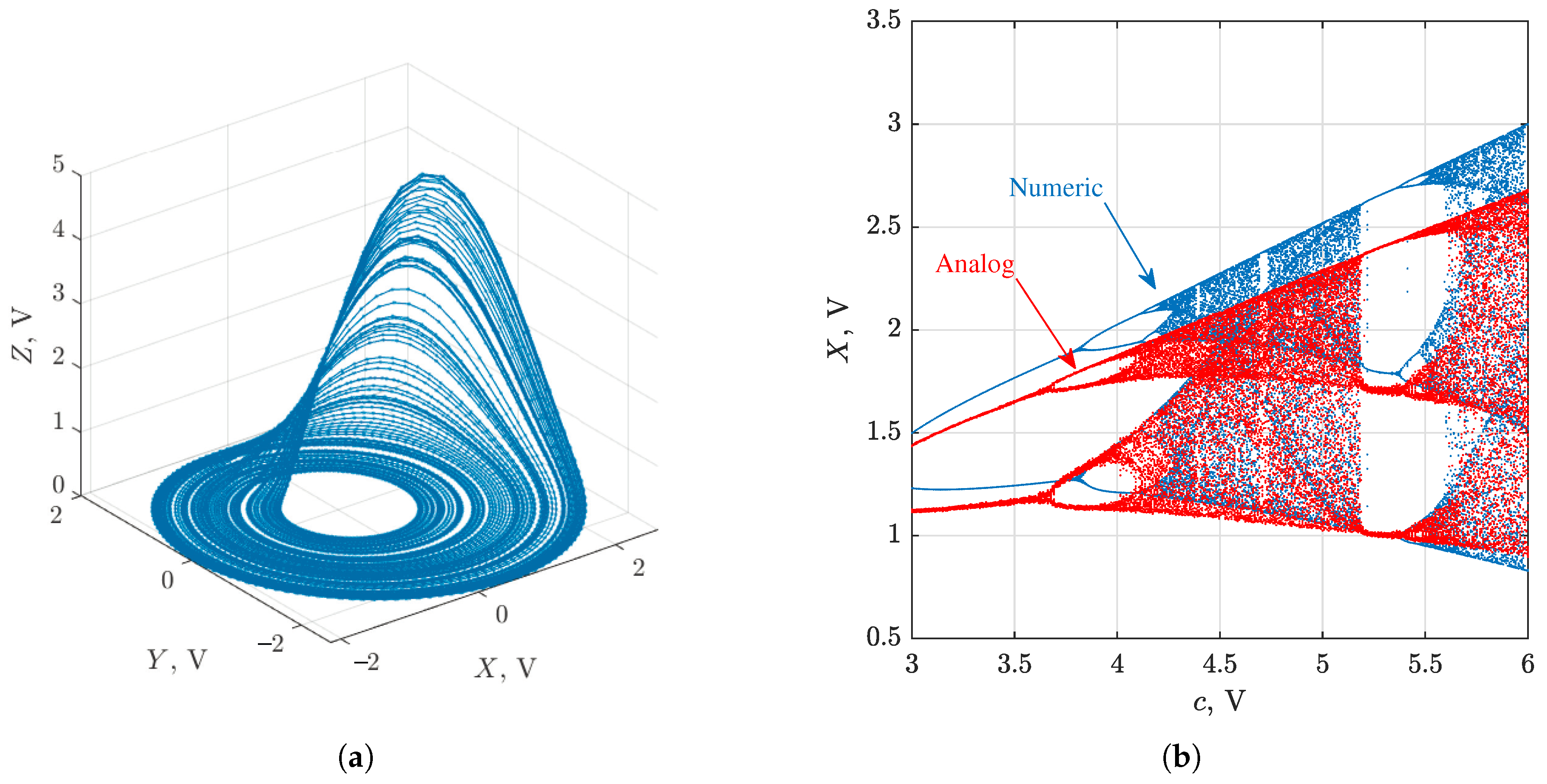
To validate the correct operation of the circuit, its phase portrait and bifurcation diagram were obtained. For the phase portrait of the analog circuit (Figure 6) with parameters a = 0.2 , b = 0.2 , c = 5.7 , refer to Figure 7a, which represents the recognizable chaotic scroll. In the bifurcation diagram (Figure 7b) which demonstrates chaotic attractor points as a function of parameter c, Feigenbaum sequences of bifurcations characterizing the Rössler system are also recognizable. Data acquisition and processing was performed using the NI ELVIS III station and the software developed in the LabVIEW 2019 environment.
However, the specific values of the nonlinearity parameters at which different oscillation modes are observed in the analog circuit differ from those in the numerical simulation. To ensure consistency between the diagrams for parameter c, the value of parameter b in the analog circuit has been adjusted. A feature of the Rössler system that makes it difficult to implement in the analog computer is the large ratio between the values of the variable z amplitude and parameter b. Therefore, in our implementation, the value b / 40 = 0.005 V was applied to the summing input of U 5 multiplier. This value is presumably of the same order of magnitude as the weak output bias present in the multiplier and also is strongly distorted by analog noise. Thus, when specifying the value b, this offset must be taken into account. In our case, the bias had a value of about 0.0025 V. Any adjustments of the value of parameter b do not lead to a complete correspondence between bifurcation diagrams, since there are other nonlinearities and errors in specifying the values of components in the analog circuit that affect its operation; in particular, the amplitudes of the attractors differ.
Thus, system (19), which is a linear transformation of system (10), does not fully characterize the dynamics of the circuit. The exact identification of non-linear components is challenging. Therefore, complete synchronization between the circuit and the mathematical model is not possible. The same result was achieved in one of our previous works [22], where the Rössler system was also considered and error attractors in case of Pecora–Carroll synchronization [1] were obtained. Note that in [22], a slightly modified Rössler oscillator with an additional parameter d was studied; additionally, another circuit was designed with the parameter c defined as the ratio between two resistors, not as an external voltage.

3.3.3. Adaptive Generalized Synchronization between Circuit and Numerical Model with Respect to Numerical Method

The experimental study of adaptive generalized synchronization between the circuit and the computer model was conducted using the following parameters of the slave system: x s , 1 = 2 , y s , 1 = 4 , z s , 1 = 2 , initial parameters a ^ 1 = 0.2 , b ^ 1 = 0.6 , c ^ 1 = 5.25 . Heun’s integration method was used, and the step-size was h = 0.0464 . The auxiliary slave system was similar. Figure 8 presents the time series of the error between the circuit and computer model, taken as the L 2 -norm of the error in dynamics, and the time series of estimated parameters. One can clearly see that the estimated parameters are oscillating and do not converge to steady-state values. This behavior shows that the perturbations caused by the introduced errors are significant and cannot be tracked by the controller well. However, the overall stability of the solution is not violated.
Figure 9 presents the synchronization error between master and slave systems for different integration methods, smoothed with the median filter. There is a clear dependence of the averaged error on the integration method. It is interesting to note that the first-order symplectic Euler–Cromer method presents an equally accurate synchronization as the second-order Heun’s method. This result is significant as it allows the use of an algebraically simpler simulation algorithm without loss of accuracy. This is of great importance in embedded applications. A rough explanation of this phenomenon can be that the Rössler system phase space is approximately isomorphic to the harmonic oscillator phase space in regions in which | z | < ε , and ε > 0 is a small real number. However, this needs to be investigated further.
Figure 10 shows the accuracy of the master–slave and slav–auxiliary systems’ synchronization achieved in our experiment. It can be compared with Figure 4, which shows that GS is preserved in the cases of analog and numeric chaotic systems.
Figure 11 illustrates one again the proposition that the rate of convergence between slave systems weakly depends on the integration method, and this can be compared with Figure 5. In the case of heterogeneous chaotic systems, the slave–auxiliary synchronization rate is approximately similar for all investigated methods. It is of interest that the averaged rate of all methods except for Euler and Trapezoidal methods is slightly superlinear.
Summarizing the results, we can conclude that, even though the master and slave systems are heterogeneous, GS is experimentally verified, as well as CS. It is shown that the synchronization error in dynamics actually depends on the numerical method. Among all investigated methods, Heun’s and Euler–Cromer methods look preferable.

3.4. Tracking an Additional Parameter in Adaptive Generalized Synchronization

Modify the Rössler system (10) as follows:
x ˙ = μ y z , y ˙ = x + a y , z ˙ = b + z ( x c ) ,
where μ is the novel parameter, which is not tracked by the controller (13). This parameter is easily tuned in the circuit by changing the only resistor R 1 . In our experiment, the following values of R 1 were used: 5 kOhms, 8 kOhms, 9 kOhms, 10 kOhms, 10.5 kOhms, 11 kOhms, 12.8 kOhms and 20 kOhms. Different attractors of the Rössler system corresponding to these values are given in Figure 12.
Parameter μ values differing from 10 kOhms introduce additional error in the implemented analog Rössler system. Attractors A e R 3 of the error in dynamics e ( n ) between the circuit implementation of the master system (20) and computer model of the slave system (12) are given in blue in Figure 13.
Then, we equip the slave system with an additional adjustable parameter μ ^ , which now reads as
x ˙ s = μ ^ y s z s u 1 , y ˙ s = x s + a ^ y s u 2 , z ˙ s = b ^ + z s ( x s c ^ ) u 3 .
Modify the adaptive controller in the following way:
u 1 = e 1 + ( z m 1 ) e 3 + ( 1 μ ^ ) e 2 , u 2 = ( 1 + a ^ ) e 2 , u 3 = ( 1 + x s c ^ ) e 3 ,
with the following update rule for parameters:
a ^ ˙ = y m e 2 , b ^ ˙ = e 3 , c ^ ˙ = z m e 3 , μ ^ ˙ = y m e 1 .
After substituting (20)–(23) into Equation (9) from [27], it is easy to see that the slave system (21) completely synchronizes with the system (20).
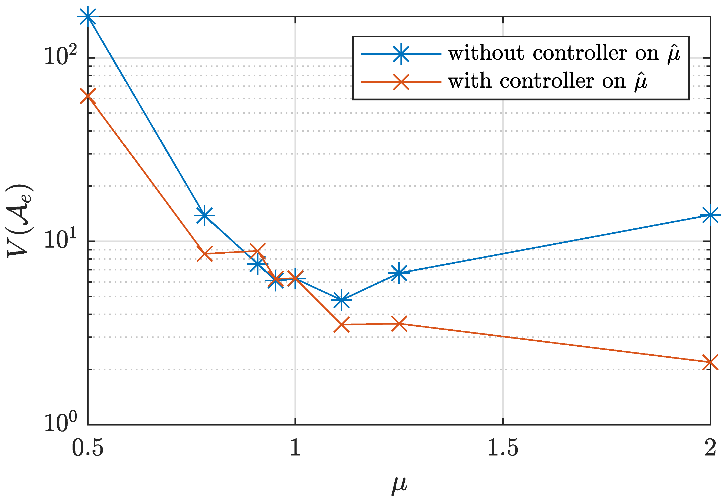
The actual error in synchronization between the circuit and digital implementation of the system (20) using Heun’s method with a step-size of h = 0.0518 s is given in red in Figure 12. This is substantially smaller in comparison with the error of the system (21). To obtain a quantitative measure of error attractors, we used the attractor L 1 -volume V L 1 ( A e ) = j = x , y , z ( max n ( e j ( n ) ) min n ( e j ( n ) ) ) . Its estimations are given in Figure 14.
One can see that additional system perturbation with the parameter μ increases the synchronization error when this parameter is not tracked, and the new value of μ sufficiently differs from 1. At the same time, tuning the corresponding parameter μ ^ allows a notable reduction of the synchronization error.
To estimate the error in the parameter μ identification, the median value over 9000 samples of μ ^ ( n ) was computed. The estimated R 1 was calculated as
R ^ 1 = R 0 M n = 1 . . 9 · 10 3 ( μ ^ ( n ) ) ,
where M is the median and R 0 is 10 kOhms. Obtained results are given in Figure 15.
Although there was no complete synchronization between analog and computer systems, the relative error of parameter identification was on average less than 1.5 % . This shows the practical applicability of this approach as a parameter identification technique.

4. Conclusions

For two chaotic systems of arbitrary natures that are close to each other in a reasonable sense, it is possible to achieve generalized synchronization. According to Conjecture 1, the synchronization error tends to vanish if the system difference becomes negligible. Once the driven system is equipped with the parameter estimation controller, one can fit uncertain parameters of the driving system even though there is no straight correspondence between the systems.
To experimentally verify Conjecture 1, we developed a novel design of a circuit modeling a Rössler chaotic system. Generalized synchronization between the circuit and computer models was established, and the synchronization error was estimated.
Several first and second-order integration methods were tested. We experimentally confirmed that the methods of a higher-accuracy order can improve the synchronization accuracy in computer simulations. The best result was obtained by Heun’s method. It is of interest that the symplectic Euler–Cromer method gave almost similar results to Heun’s method, with first-order accuracy and increased computationally efficiency.
We show that the use of adaptive generalized synchronization allows the parameters of an analog system to be tracked. We implemented a controller monitoring the parameter vector and found that the median value of one uncertain parameter fitted by this controller corresponds to the analog value with high accuracy. This opens the possibility of applying adaptive generalized synchronization for identification, secure communication and sensing using complete adaptive synchronization.
In future works, we will apply the developed approach to study other chaotic systems and also consider practical examples of applying adaptive generalized synchronization according to our findings. A more complete investigation of how symplectic methods can be used for the simulation of non-conservative chaotic systems will also be a topic of further investigation.

Author Contributions

Conceptualization, A.T. and D.B.; data curation, T.K. and O.D.; formal analysis, A.K.; funding acquisition, D.B.; investigation, A.K., A.T., T.K. and O.D.; methodology, A.K., A.T. and D.B.; project administration, D.B.; resources, T.K. and D.B.; software, A.K., A.T. and O.D.; supervision, D.B.; validation, T.K., O.D. and D.B.; visualization, A.K., A.T. and T.K.; writing—original draft, A.K., A.T. and T.K.; writing—review & editing, D.B. All authors have read and agreed to the published version of the manuscript.

Funding

This research was funded by the Russian Foundation for Basic Research (RFBR), grant number 19-07-00496.

Informed Consent Statement

This article does not contain any studies with human participants or animals.

Data Availability Statement

No new data were created or analyzed in this study. Data sharing is not applicable to this article.

Acknowledgments

We thank the anonymous reviewers for their careful reading of our manuscript and their many insightful comments and suggestions.

Conflicts of Interest

The authors declare no conflict of interest.

References

  1. Pecora, L.M.; Carroll, T.L. Synchronization in chaotic systems. Phys. Rev. Lett. 1990, 64, 821. [Google Scholar] [CrossRef] [PubMed]
  2. Pecora, L.M.; Carroll, T.L. Synchronization of chaotic systems. Chaos Interdiscip. J. Nonlinear Sci. 2015, 25, 097611. [Google Scholar] [CrossRef] [PubMed]
  3. Eroglu, D.; Lamb, J.; Pereira, T. Synchronization of Chaos. arXiv 2017, arXiv:1703.08296. [Google Scholar]
  4. Rulkov, N.F.; Sushchik, M.M.; Tsimring, L.S.; Abarbanel, H.D. Generalized synchronization of chaos in directionally coupled chaotic systems. Phys. Rev. E 1995, 51, 980. [Google Scholar] [CrossRef]
  5. Abarbanel, H.D.; Rulkov, N.F.; Sushchik, M.M. Generalized synchronization of chaos: The auxiliary system approach. Phys. Rev. E 1996, 53, 4528. [Google Scholar] [CrossRef] [Green Version]
  6. Tandon, A.; Schröder, M.; Mannattil, M.; Timme, M.; Chakraborty, S. Synchronizing noisy nonidentical oscillators by transient uncoupling. Chaos Interdiscip. J. Nonlinear Sci. 2016, 26, 094817. [Google Scholar] [CrossRef] [Green Version]
  7. Ouannas, A.; Odibat, Z. On inverse generalized synchronization of continuous chaotic dynamical systems. Int. J. Appl. Comput. Math. 2016, 2, 1–11. [Google Scholar] [CrossRef] [Green Version]
  8. Uchida, A.; McAllister, R.; Roy, R. Consistency of nonlinear system response to complex drive signals. Phys. Rev. Lett. 2004, 93, 244102. [Google Scholar] [CrossRef]
  9. Liao, T.L.; Tsai, S.H. Adaptive synchronization of chaotic systems and its application to secure communications. Chaos Solitons Fractals 2000, 11, 1387–1396. [Google Scholar] [CrossRef]
  10. Behinfaraz, R.; Badamchizadeh, M.; Ghiasi, A.R. An adaptive method to parameter identification and synchronization of fractional-order chaotic systems with parameter uncertainty. Appl. Math. Model. 2016, 40, 4468–4479. [Google Scholar] [CrossRef]
  11. Wu, X.; Wang, J. Adaptive generalized function projective synchronization of uncertain chaotic complex systems. Nonlinear Dyn. 2013, 73, 1455–1467. [Google Scholar] [CrossRef]
  12. Li, C.; Min, F.; Li, C. Multiple coexisting attractors of the serial–parallel memristor-based chaotic system and its adaptive generalized synchronization. Nonlinear Dyn. 2018, 94, 2785–2806. [Google Scholar] [CrossRef]
  13. Wang, S.; Wang, X.; Han, B. Complex generalized synchronization and parameter identification of nonidentical nonlinear complex systems. PLoS ONE 2016, 11, e0152099. [Google Scholar] [CrossRef] [PubMed]
  14. Li, R.h.; Xu, W.; Li, S. Adaptive generalized projective synchronization in different chaotic systems based on parameter identification. Phys. Lett. A 2007, 367, 199–206. [Google Scholar] [CrossRef]
  15. Gu, Y.; Wang, H.; Yu, Y. Synchronization for commensurate Riemann-Liouville fractional-order memristor-based neural networks with unknown parameters. J. Frankl. Inst. 2020, 357, 8870–8898. [Google Scholar] [CrossRef]
  16. Liu, C.; Wang, F. Parameter identification of genetic regulatory network with time-varying delays via adaptive synchronization method. Adv. Differ. Equ. 2020, 2020, 127. [Google Scholar] [CrossRef] [Green Version]
  17. Zhang, J.; Zhang, W.; Yang, C.; Wang, H.; Qiu, J.; Alsaadi, F. Parameter Identification and Adaptive Control of Uncertain Goodwin Oscillator Networks with Disturbances. Complexity 2018, 2018, 6483078. [Google Scholar] [CrossRef]
  18. Jin, L.; Wang, X.; Li, L. Chaotic synchronization of two microresonators with application in mass sensors. J. Appl. Phys. 2013, 113, 093506. [Google Scholar] [CrossRef]
  19. Karimov, T.; Butusov, D.; Karimov, A.; Druzhina, O.; Khalyasmaa, A. The Detection of Small Inductance Changes by Synchronized Chaotic Oscillators. In Proceedings of the 2019 International Multi-Conference on Engineering, Computer and Information Sciences (SIBIRCON), Novosibirsk, Russia, 21–27 October 2019; pp. 0120–0124. [Google Scholar]
  20. Siderskiy, V.; Kapila, V. Parameter matching using adaptive synchronization of two Chua’s oscillators. Int. J. Bifurc. Chaos 2014, 24, 1430032. [Google Scholar] [CrossRef]
  21. Gintautas, V.; Hübler, A.W. Experimental evidence for mixed reality states in an interreality system. Phys. Rev. E 2007, 75, 057201. [Google Scholar] [CrossRef] [PubMed] [Green Version]
  22. Karimov, T.; Butusov, D.; Andreev, V.; Karimov, A.; Tutueva, A. Accurate synchronization of digital and analog chaotic systems by parameters re-identification. Electronics 2018, 7, 123. [Google Scholar] [CrossRef] [Green Version]
  23. Butusov, D.N.; Karimov, T.I.; Lizunova, I.A.; Soldatkina, A.A.; Popova, E.N. Synchronization of analog and discrete Rössler chaotic systems. In Proceedings of the 2017 IEEE Conference of Russian Young Researchers in Electrical and Electronic Engineering (EIConRus), St. Petersburg, Russia, 1–3 February 2017; pp. 265–270. [Google Scholar]
  24. Rossler Data and Software in MATLAB. 2020. Available online: https://github.com/aikarimov/Rossler_simulation (accessed on 24 November 2020).
  25. OPA2134 Data Sheet. 2020. Available online: https://www.ti.com/product/OPA2134 (accessed on 19 November 2020).
  26. Nepomuceno, E.G.; Mendes, E.M. On the analysis of pseudo-orbits of continuous chaotic nonlinear systems simulated using discretization schemes in a digital computer. Chaos Solitons Fractals 2017, 95, 21–32. [Google Scholar] [CrossRef]
  27. Park, J.H. Adaptive synchronization of Rossler system with uncertain parameters. Chaos Solitons Fractals 2005, 25, 333–338. [Google Scholar] [CrossRef]
Figure 1. Sources of error in analog-to-numeric synchronization.
Applsci 11 00081 g001
Figure 2. (a) Synchronization error between master and slave system. (b) Evaluation of parameters for the slave system.
Applsci 11 00081 g002
Figure 3. Synchronization error between master and slave systems for different integration methods, smoothed with a median filter; the window size is 600 samples.
Applsci 11 00081 g003
Figure 4. Synchronization error between computer models, smoothed with a median filter; the window size is 600 samples.
Applsci 11 00081 g004
Figure 5. Synchronization error between slave systems for different integration methods, smoothed with a median filter; the window size is 600 samples.
Applsci 11 00081 g005
Figure 6. Circuit implementing the Rössler chaotic system with parameters b and c defined as input voltages. Circuit state variables X, Y and Z presented as voltages are down-scaled by M = 4 compared to their numerical counterparts.
Applsci 11 00081 g006
Figure 7. (a) Attractor produced by the circuit. (b) Bifurcation diagrams of overlaid numerical (Runge–Kutta 4) and analog systems. Parameter b = 0.2 was used for the numerical system, and parameter b = 0.3 for the analog system.
Applsci 11 00081 g007
Figure 8. (a) Synchronization error between circuit and computer model. (b) Evaluation of parameters for the slave system.
Applsci 11 00081 g008
Figure 9. Synchronization error between master and slave systems for different integration methods, smoothed with a median filter; the window size is 200 samples.
Applsci 11 00081 g009
Figure 10. Synchronization error between computer models simulated by Heun’s method. Time sequences are smoothed with a median filter; the window size is 200 samples.
Applsci 11 00081 g010
Figure 11. Synchronization error between slave systems for different integration methods, smoothed with a median filter; the window size is 200 samples.
Applsci 11 00081 g011
Figure 12. Attractors acquired from the Rössler modeling circuit with mathematical parameter values a = b = 0.2 ,   c = 5.7 and the altered resistor R 1 . Here, μ = R 0 / R 1 . The case μ = 1 corresponds to a normal Rössler oscillator; other cases show the deliberate corruption of the system.
Applsci 11 00081 g012
Figure 13. Error attractors between the circuit and the computer model: blue for the slave system (12) and red for the slave system (21).
Applsci 11 00081 g013
Figure 14. Dependence of the error attractor L 1 -volume on the parameter μ value for slave systems without and with a controller on μ ^ , corresponding to slave systems (12) and (21), respectively.
Applsci 11 00081 g014
Figure 15. (a) Resistance R 1 identification results; (b) Evaluation of relative error in R 1 identification: the plot shows the actual R 1 value versus the relative error of its estimation | Δ R 1 R 1 | , where Δ R 1 = R 1 ^ R 1 .
Applsci 11 00081 g015
Publisher’s Note: MDPI stays neutral with regard to jurisdictional claims in published maps and institutional affiliations.