Article

Control of Timing Stability, and Suppression in Delayed Feedback Induced Frequency-Fluctuations by Means of Power Split Ratio and Delay Phase-Dependent Dual-Loop Optical Feedback

by
Haroon Asghar
1,2,3,* and
John G. McInerney
1,4
1
Department of Physics and Tyndall National Institute, University College Cork, Western Road, T12 YN60 Cork, Ireland
2
National Center for Physics, Quaid-i-Azam University Campus, Islamabad 45320, Pakistan
3
Department of Physics, School of Science, Sialkot Campus, University of Management and Technology (UMT), Sialkot 51310, Pakistan
4
College of Optical Sciences, University of Arizona, Tucson, AZ 85721, USA
*
Author to whom correspondence should be addressed.
Appl. Sci. 2021, 11(10), 4529; https://doi.org/10.3390/app11104529
Submission received: 12 April 2021 / Revised: 9 May 2021 / Accepted: 12 May 2021 / Published: 16 May 2021
(This article belongs to the Section Applied Physics General)

Abstract

:
We experimentally demonstrated a power split ratio and optical delay phase dependent dual-loop optical feedback to investigate the suppression of frequency-fluctuations induced due to delayed optical feedback. The device under investigation is self-mode-locked (SML) two-section quantum-dash (QDash) laser operating at ∼21 GHz and emitting at ∼1.55 μm. The effect of two selective combinations of power split ratios (Loop-I: −23.29 dB and Loop-II: −28.06 dB, and Loop-I and Loop-II: −22 dB) and two optical delay phase settings ((i) stronger cavity set to integer resonance and fine-tuning the weaker cavity, (ii) weaker cavity set to integer resonance and fine-tuning of stronger cavity) on the suppression of cavity side-bands have been studied. Measured experimental results demonstrate that delayed optical feedback induced frequency-fluctuations can be effectively suppressed on integer resonance as well as on full delay range tuning (0–84 ps) by adjusting coupling strength −22 dB through Loop-I and Loop-II, respectively. Our findings suggest that power split ratio and delays phase-dependent dual-loop optical feedback can be used to maximize the performance of semiconductor mode-locked lasers.

1. Introduction

High frequency and low phase-noise optoelectronic oscillators (OEOs) are essential elements having potential applications in optical telecommunication [1], radar systems [2], high-speed clock recovery [3], frequency comb [4] and pulse generation [5]. Yao and Maleki first introduced a novel photonic oscillator that converted continuous light energy into spectrally pure and stable microwave signals [6,7]. To achieve ultra-low phase-noise in OEOs, long loop delay provided by optical fiber is highly desirable, as the phase-noise in OEOs is inversely proportional to the length of loop delay [7]. High-performance OEOs significantly improves the phase-noise by converting optical oscillations into electrical oscillations from a long optical feedback loop but creates coherent frequency-fluctuations close to the fundamental mode-locked frequency which restrict their targeted applications [8]. Beside OEOs, the noise-induced random fluctuations appear in chemical reaction systems [9], semiconductor devices [10,11], and in many other systems including lasers [12,13]. Apart frequency-fluctuations, frequency operation and bandwidth of the electric component further constraint the practical applications of conventional OEOs.
Quantum nanostructure-based semiconductor mode-locked lasers (SMLLs) have received much attention in recent years due to their potential applications in high-speed optical telecommunications [14,15], coherent wavelength division multiplexing (CoWDM) [16], arbitrary waveform generation [17,18], all-optical signal processing [19], data center applications [20] and millimeter-wave generation [21]. In 1980, Lang and Kobayashi reported some aspects of the dynamics of a semiconductor lasers exposed to external optical feedback [22,23]. Delayed optical feedback enhances stabilizing effects of SMLLs, thereby reduced the RF linewidth and corresponding integrated timing jitter [24,25,26]. Beside improving stabilization, delayed optical feedback induces cavity side-bands [27]. These cavity side-bands can be effectively suppressed by simply adding a second feedback loop (dual-loops optical feedback configurations) [28,29,30]. Dual-loops configuration can be considered as a simple, rugged and low-cost approach to eliminate frequency-fluctuations without optical/electrical conversion [31,32,33,34,35,36]. However, dual-loop optical feedback due to the resonance of the modes of second delay time to that of first, limits optimal suppression of cavity induces side-bands [33]. Therefore, the prediction of precise delay times required to effectively suppress side-bands including modal overlaps (interference of modes of second loop wit first loop) is highly desirable. Most recently, we demonstrate an asymmetric dual-loop feedback method to suppress cavity induced side-bands due to delayed optical single and dual-loop feedback [34] and results were compared with recently published numerical simulation [37] which show excellent agreement. Besides the pulse train stability of two-section SML QDash lasers was investigated by optimizing delay phase settings and power split ratio through dual-loops feedback. It was observed that symmetric dual-loop with different coupling strengths and fine-tuning of weaker cavity: far more effective than symmetric dual-loop with equal power splitting, as it reduce the timing jitter over a wider delay range as well as on integer resonance. Based on this study it was revealed that optical delay phase and power split ratio are determined to be crucial parameters in dual-loop feedback configurations that control the stability and performance of QDash SMLLs [32,36]. Recently, based on the open-loop response method, a theoretical analysis was performed on the characteristics of an electrically combined dual-loop optoelectronic oscillator. It was observed that the performance of OEOs including phase-noise, side-mode suppression, and loop-efficiency can be improved by controlling the two key parameters: optical delay phase settings and power split ratio [38]. In [34], the influence of the equal power split ratio and different cavity lengths on the side-mode suppression was studied. However, the dependence of the side-bands suppression on the loop parameters (optical delay phase settings and power split ratio) was neglected.
Here we present an optical delay phase and power split ratio dependant dual-loop optical feedback configurations to suppress delayed optical feedback induced cavity side-bands. The device studied was dual-section QDash MLL with emission wavelength ∼1.55 μm and pulse repetition rates ∼21 GHz. The experimental analysis was conducted based on two chosen combinations of feedback ratios and two optical delay phase settings.

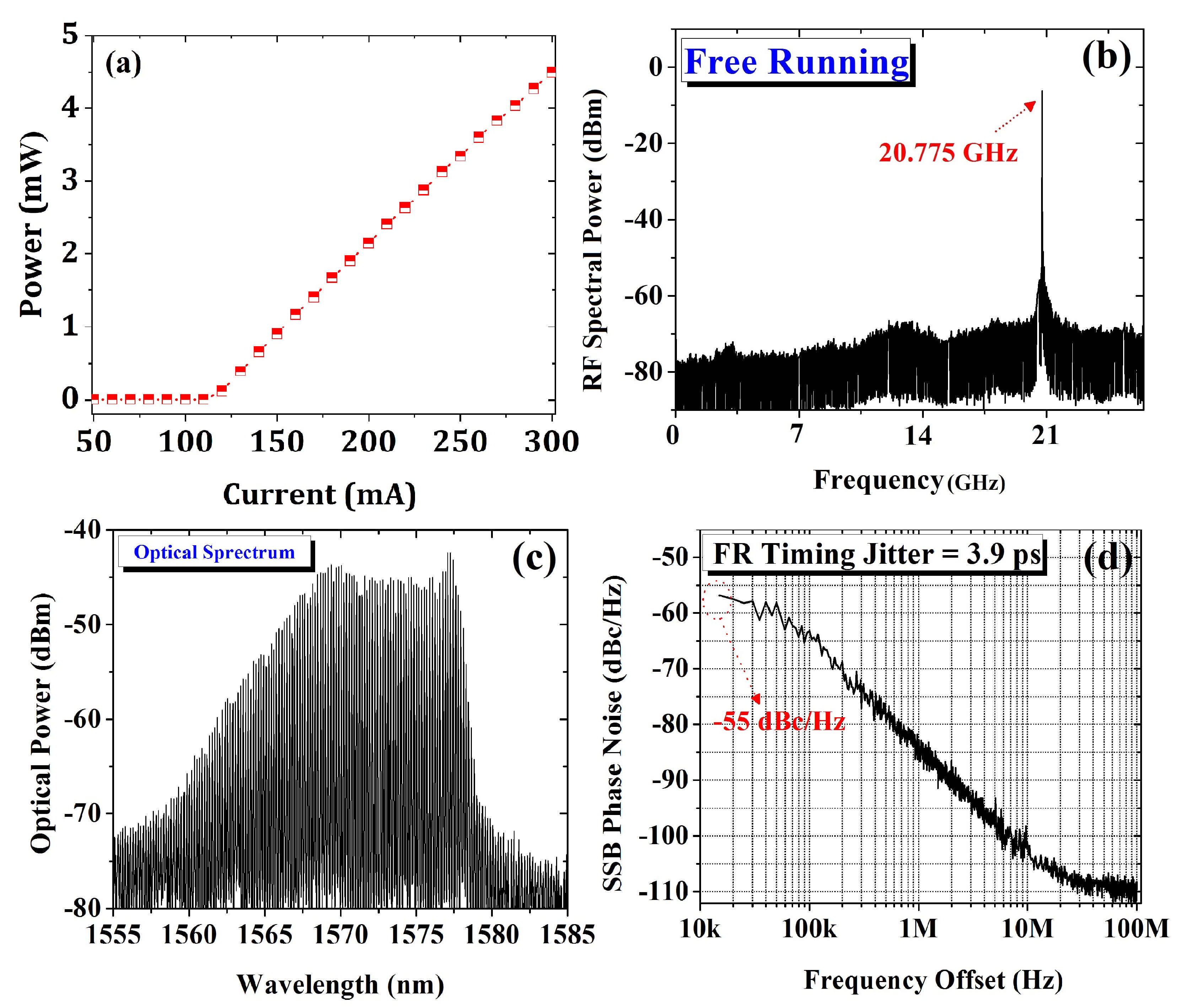
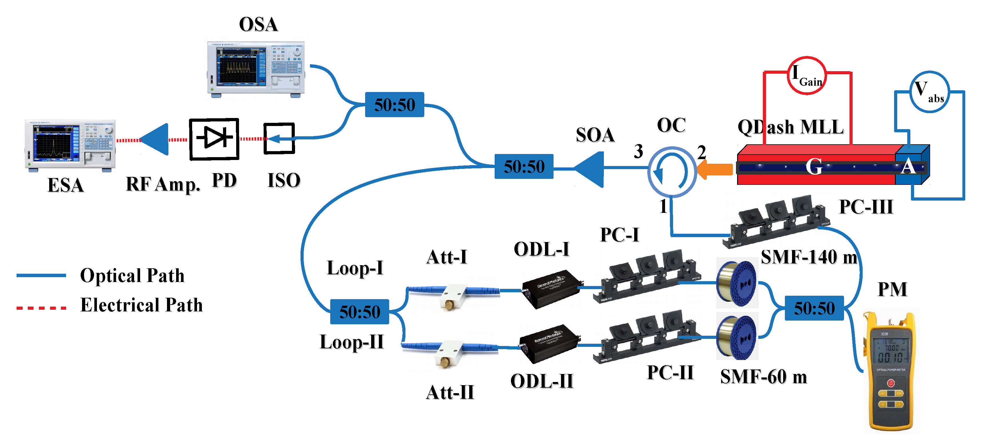
2. Experimental Arrangements

The laser under investigation is two-section InAs/InP QDash SMLLs with active layers consist of 9 InAs QDash monolayers [39]. The laser is similar to that described in [32,34]. The emission wavelength of laser is ∼1.55 μm and operating frequency is around ∼21 GHz. The total cavity length of the laser was 2030 μm including 240 μm length of absorber section. The gain section of the laser was operated at fixed gain current 300 mA with a average free-space output powers of a few mW. The L-I characteristics of SML QDash lasers are shown in Figure 1a from the current ranges from 50 mA to 300 mA with the threshold at 120 mA. Furthermore, the temperature of the laser was fixed at 19 C.
The diagram of the experimental arrangement is shown in Figure 2. The light from the QDash MLL was coupled into lensed fibre through port 2 of an optical circulator and then coupled into a semiconductor amplifier through port 3. After amplification, the light was then equally splited via 3-dB coupler. Half of the light was used for the analysis of optical and RF spectra. RF spectrum was captured using RF spectrum analyzer (Keysight E-series, E4407B) via 21 GHz photodiode. Figure 1b shows RF spectra under full frequency span [0–26.5 GHz]. The minimum RF linewidth was measured to be 100 kHz for the case of free-running laser. Besides the optical spectrum of the QDash MLL was recorded using a diffraction-grating based commercial optical spectrum analysers (Ando AQ6317B) covering the infrared wavelength range up to 1700 nm with a minimum resolution bandwidth of 0.01 nm. Measured optical spectrum of SML QDash laser under free-running condition is shown in Figure 1c. The spectrum was centered at 1570 nm with a 3 dB bandwidth spanning 12 nm and containing 68 longitudinal modes, with 0.18 nm free spectral range (FSR). The other half was fed into a dual-loop feedback configuration. Each feedback loop composed of a polarization controller (PC), variable optical attenuator (Att) and optical delay line (ODL). In each feedback loop the coupling strength was adjusted using a variable optical attenuator. The overall feedback ratio was fed into the gain section of the laser through port 1 of an optical circulator and feedback strength was monitored using a power meter. The microscopic length of the fibre loops were optimized by optical delay lines attached with each feedback loop. Single side-band (SSB) phase noise trace of the free-running laser under integration limits 10 kHz–100 MHz is shown in Figure 1d and minimum timing jitter was measured to be as low as 3.9 ps.

3. Results and Discussion

Semiconductor lasers are extremely sensitive to external optical feedback [22] and this technique has been proven to be an effective means of stabilizing SMLLs. Like single-loop optical feedback, dual-loop optical feedback configurations have a significant effect on the stabilization of SMLLs [28,31,32,33,34,35,36]. The major advantage of adding a feedback cavity to single-loop feedback provides additional control on parameters including optical delay line, variable optical attenuator and polarization controller. These parameters have a significant influence on the stability of QDash MLLs including suppression noise-induced oscillations subject to delayed optical feedback.

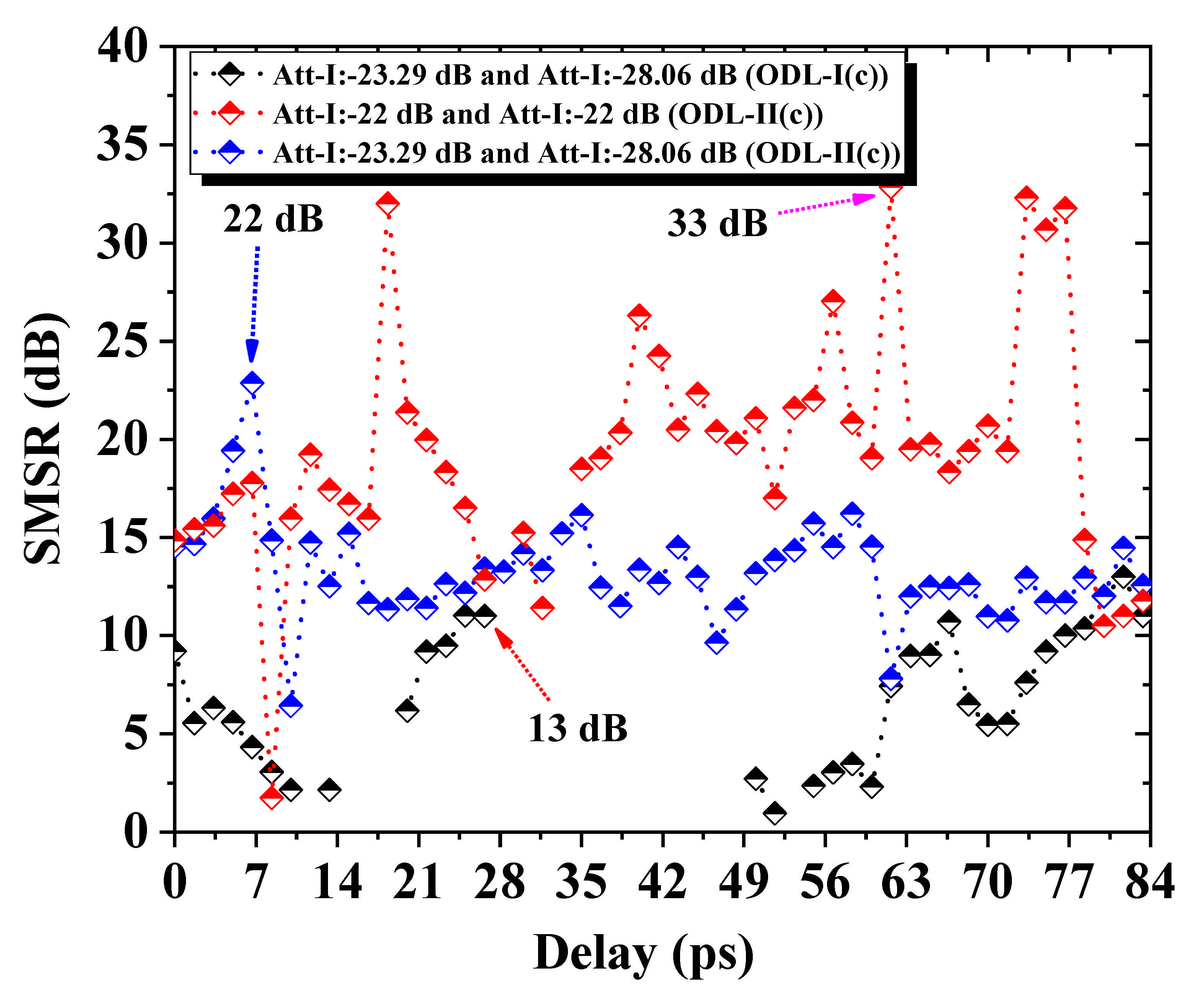
3.1. Effect of Coupling Strengths and Delay Phase Settings on the Suppression of Cavity Induced Frequency-Fluctuations

High performance of SMLLs including low timing jitter and narrow RF linewidth can be achieved using long fiber spool in a feedback loop. With low phase-noise, such feedback configuration induces narrowly spaced noise-oscillations close to the fundamental mode-locked frequency. Frequency spacing around the target frequency depends on the length of external feedback loops.
In the following, we discussed the effects of two chosen feedback strengths (Loop-I: −23.29 dB and Loop-II: −28.06 dB, Loop-I and Loop-II: −22 dB) and two optical delay phase settings (weaker cavity set to integer resonance, fine-tuning of stronger cavity and stronger cavity set to integer resonance, fine-tuning of weaker cavity) on the suppression of external cavity induced frequency-fluctuations.

3.1.1. Loop-I: ∼−23.29 dB and Loop-II: ∼−28.06 dB (Fine-Tuning of Stronger Cavity and Set Weaker Cavity to Fully Resonance)

First, higher coupling strength was fixed through loop-I (∼−23.29 dB) and lower feedback ratio through loop-II (∼−28.06 dB). The ODL-II attached with loop-II was adjusted to fully resonance and ODL-I(c) was fine-tuned over maximum available delay range, 0–84 ps. Measured side-band suppression versus microscopic fine-tunable delay (0–84 ps) is shown in Figure 3 (black squares). A maximum 13 dB suppression in first-order side-band was achieved when the mode of loop-I coincides precisely with that of loop-II (at optical delay phase setting 28 ps). With this selected combination of feedback ratio, the SMSR varies in between 0 dB to 13 dB from delay range (0–28 ps). However, when the delay was tuned from 28 to 49 ps, no SMSR was achieved because the laser was unstable between these delay ranges and no significant suppression in cavity side-band occurred.

3.1.2. Loop-I: ∼−23.29 dB and Loop-II: ∼−28.06 dB (Fine-Tuning of Weaker Cavity and Set Stronger Cavity to Fully Resonance)

The SMSR was further investigated for feedback coupling ratio ∼−23.29 dB through loop-I and ∼−28.06 dB through loop-II. Besides ODL-I was adjusted to integer resonance and ODL-II was fine-tuned. Measured side-band suppression versus microscopic fine-tunable delay (0–84 ps) is shown in Figure 3 (blue squares). It can be seen that under integer resonance a maximum 22 dB side-mode suppression was achieved (at optical delay phase setting ∼7 ps) which was ∼2× higher than the previous combination. Furthermore, on maximum available delay range (0–84 ps), a better side-band suppression was observed. It should be noted that coupling strength was similar to that discussed above (Loop-I: ∼−23.29 dB and Loop-II: ∼−28.06 dB) but fine-tuning of optical delay setting were different. This better stabilization results due to less sensitivity of optical delay phase setting [36].

3.1.3. Loop-I: ∼−22 dB and Loop-II: ∼−22 dB

We also assessed the influence of equal coupling strengths (Loop-I: ∼−22 dB and Loop-II: ∼−22 dB) from both external feedback cavities on the cavity induced side-bands. The feedback strength in both feedback loops was adjusted using variable optical attenuator attached in each external feedback cavity. This arrangement yields optimum suppression in cavity induced side-modes and under full resonance, a maximum 33 dB suppression in first harmonic occurred. Besides, on full delay range (0–84 ps), side-band suppression takes place from 13 to 33 dB. Side-band suppression versus delay is shown in Figure 3 (red squares).
Measured experimental SMSR on integer resonance as well as on full delay range (0–84 ps) are summarized in Table 1 under three chosen combinations of power split ratios and optical delay phase settings. In column 1, coupling strength is given, SMSR at integer resonance is listed in column 2, and SMSR versus maximum available delay range tuning (0–84 ps) are presented in column 3.

4. Key Parameters Desired to Optimize External Cavity Induced Side-Bands

Measured experimental results demonstrates that side-band suppression depends on the three key parameters: lengths of both feedback loops, coupling strengths in each cavity, and optical delay phase settings attached within each loop. A theoretical analysis was conducted on the dual-loop optoelectronic oscillator and it was found that characteristics and performance depend on parameters including coupling strength ratio and delay phase setting [38]. The parameters mentioned above are discussed below.
Loop-Length: The suppression of external cavity induced frequency-fluctuations depends on the length of second feedback delay-time relative to first. By simply choosing the second loop length equal to half the length of the first loop, suppress first harmonics of frequency while second harmonics remained unsuppressed. When the second delay time was resonant with the third harmonics of the first loop, two harmonics suppressed while third remain unsuppressed and appeared as modal overlap [34]. In [34], dual-loop feedback with large (8×) disparity in loop lengths was introduced gives significant suppression in noise-oscillations and produces flat RF spectra close to the main peak. Therefore, for better suppression of external cavity side-bands, a precise length of the second delay time is highly desirable. Most recently, the suppression of noise-induced modulations in oscillatory systems using an additional feedback term was theoretically investigated [37].
Power split ratio: Dual-loop optical feedback with the power split ratio has a significant influence on the suppression of external cavity induced side-bands. The different coupling strengths via single- and dual-loop optical feedback influence the RF linewidth of our device under investigation [36]. Measured experimental results in Section 3.1 demonstrates that side-band suppression depends on the power split ratio through each external feedback loop. Better side-mode suppression can be achieved when equal coupling strength (∼−22 dB:∼−22 dB) passes through both feedback loops relative to other chosen combinations of feedback ratios and delay settings (∼−23.29 dB(c):∼−28.06 dB and ∼−23.29 dB:∼−28.06 dB(c)). Unbalanced (different percentage of power split ratio) symmetric dual-loop was studied to achieve optimum stabilization in SML QDash laser [36]. It was also observed that balanced (equal percentage of feedback strength) symmetric dual-loop optical feedback leads QDash MLLs towards destabilization [32]. However, in this contribution, we observed that better side-band suppression was achieved under a balanced feedback ratio through asymmetric (loop-I: 160 m and loop-II: 80 m) dual-loop optical feedback configuration. The first-factor influence side-band suppression due to overlap of frequency spacing of modes of loop-I with that of loop-II, at the 3 dB coupler. The second factor that caused the suppression is the coupling strength through each external feedback cavity.
Delay phase-tuning: Similar to loop lengths and power split ratio, the optical delay phase setting is another key parameter by tuning which the characteristics and efficiency of the SMLLs could be efficiently controlled. Most recently, a comprehensive analysis based on different optical delay phase settings and power split ratio is presented [36]. Including timing stability, optical delay phase settings improve external cavity induced side-band suppression. Measured results indicate that upon tuning of ODL-I, the side-mode suppression on full delay was below 13 dB with coupling strength −23.29(c):−28.06 (refer. Figure 3: black squares). However, when ODL-II was tuned the side-band suppression was much improved and at most of the delay settings side-mode suppression was lower than 22 dB at coupling strength −23.29:−28.06(c) (refer. Figure 3: blue squares). This occurred when stronger cavity is finely tuned then ODL-I becomes highly sensitive to frequency pulling, consequently the modes of loop-I does not precisely coincides with modes of loop-II. Therefore, broaden RF linewidth and less side-band suppression was noticed. However, when second delay line (with weaker coupling strength) becomes less sensitive to frequency pulling, precise coincidence occurs at the 3 dB coupler and better side-band suppression was achieved. In [32], we demonstrate that unbalanced symmetric dual-loop feedback, with the inner cavity resonant and fine delay tuning of the outer loop, gives the narrowest RF linewidth and reduced timing jitter over a wide range of delay.

5. Conclusions

We have investigated a power split ratio and optical delay phase dependent asymmetric dual-loop optical feedback to study suppression of frequency-fluctuations induced due to longer feedback cavities. Self-mode-locked (SML) two-section quantum-dash (QDash) laser operating at ∼21 GHz and emitting at ∼1.55 μm was device under investigation. This study revealed that efficiency and performance of dual-loop optical feedback including better side-band suppression can be achieved by controlling three key parameters: lengths of each external feedback cavities, coupling strengths and optical delay phase settings of both feedback loop. Measured experimental results further demonstrates that dual-loop optical feedback with power split ratio (∼−22 dB: ∼−22 dB) including longer feedback cavity at integer resonance and fine-tuning of shorter feedback cavity yield better side-band suppression (>33 dB) at integer resonance as well as on full delay range tuning (0–84 ps) (13–33 dB). This study suggest that asymmetric dual-loop optical feedback is a cost-effective and inexpensive solution to eliminate external cavity induced noise-fluctuations and offers compact and efficient OEOs for fully monolithic integration.

Author Contributions

Supervision, J.G.M.; Writing—original draft, H.A. All authors have read and agreed to the published version of the manuscript.

Funding

European Office of Aerospace Research and Development (FA9550-14-1-0204); Science Foundation Ireland (SFI) (12/IP/1658).

Conflicts of Interest

The authors declare no conflict of interest.

References

  1. Devgan, P. A review of optoelectronic oscillators for high speed signal processing applications. ISRN Electron. 2013, 2013, 401969. [Google Scholar] [CrossRef]
  2. Jiang, F.; Lam, H.Q.; Zhou, J.; Zhang, H.; Shum, P.P.; Zhang, X. Application of coupled optoelectronic oscillator on optical sampling. Procedia Eng. 2016. [Google Scholar] [CrossRef] [Green Version]
  3. Devgan, P. Applications of optoelectronic oscillators for high speed clock recovery and RF signal discrimination. In Proceedings of the 2014 IEEE Photonics Conference, San Diego, CA, USA, 12–16 October 2014; pp. 410–411. [Google Scholar]
  4. Dai, J.; Xu, X.; Wu, Z.; Dai, Y.; Yin, F.; Zhou, Y.; Li, J.; Xu, K. Self-oscillating optical frequency comb generator based on an optoelectronic oscillator employing cascaded modulators. Opt. Express 2015, 23, 30014–30019. [Google Scholar] [CrossRef] [PubMed]
  5. Zhou, P.; Zhang, F.; Gao, B.; Pan, S. Optical pulse generation by an optoelectronic oscillator with optically injected semiconductor laser. IEEE Photonics Technol. Lett. 2016, 28, 1827–1830. [Google Scholar] [CrossRef]
  6. Yao, X.S.; Lutes, G.F.; Maleki, L.; Cao, X. Novel photonic clock and carrier recovery device. In Proceedings of the 27th Annual Precise Time and Time Interval Systems and Applications Meeting, San Diego, CA, USA, 29 November–1 December 1995; Volume 2556, pp. 118–128. [Google Scholar]
  7. Yao, X.S.; Lutes, G. A high-speed photonic clock and carrier recovery device. IEEE Photonics Technol. Lett. 1996, 8, 688–690. [Google Scholar] [CrossRef]
  8. Bánky, T.; Horváth, B.; Berceli, T. Optimum configuration of multiloop optoelectronic oscillators. JOSA B 2006, 23, 1371–1380. [Google Scholar] [CrossRef]
  9. Beato, V.; Sendina-Nadal, I.; Gerdes, I.; Engel, H. Noise-induced wave nucleations in an excitable chemical reaction. Phys. Rev. E 2005, 71, 035204. [Google Scholar] [CrossRef] [Green Version]
  10. Stegemann, G.; Balanov, A.G.; Schöll, E. Noise-induced pattern formation in a semiconductor nanostructure. Phys. Rev. E 2005, 71, 016221. [Google Scholar] [CrossRef]
  11. Hizanidis, J.; Balanov, A.; Amann, A.; Schöll, E. Noise-induced front motion: Signature of a global bifurcation. Phys. Rev. Lett. 2006, 96, 244104. [Google Scholar] [CrossRef] [Green Version]
  12. Giacomelli, G.; Giudici, M.; Balle, S.; Tredicce, J.R. Experimental evidence of coherence resonance in an optical system. Phys. Rev. Lett. 2000, 84, 3298. [Google Scholar] [CrossRef] [Green Version]
  13. Ushakov, O.V.; Wünsche, H.; Henneberger, F.; Khovanov, I.A.; Schimansky-Geier, L.; Zaks, M.A. Coherence resonance near a Hopf bifurcation. Phys. Rev. Lett. 2005, 95, 123903. [Google Scholar] [CrossRef] [Green Version]
  14. Shamim, M.H.M.; Shemis, M.A.; Shen, C.; Oubei, H.M.; Ng, T.K.; Ooi, B.S.; Khan, M.Z.M. Investigation of Self-Injection Locked Visible Laser Diodes for High Bit-Rate Visible Light Communication. IEEE Photonics J. 2018, 10, 7905611. [Google Scholar] [CrossRef]
  15. Khan, M.T.A.; Shemis, M.A.; Ragheb, A.M.; Esmail, M.A.; Fathallah, H.A.; Alshebeili, S.; Khan, M.Z.M. 4 m/100 Gb/s Optical Wireless Communication Based on Far L–Band Injection Locked Quantum-Dash Laser. IEEE Photonics J. 2017, 9, 7901807. [Google Scholar] [CrossRef]
  16. Kemal, J.N.; Marin-Palomo, P.; Panapakkam, V.; Trocha, P.; Wolf, S.; Merghem, K.; Lelarge, F.; Ramdane, A.; Randel, S.; Freude, W.; et al. Coherent WDM transmission using quantum-dash mode-locked laser diodes as multi-wavelength source and local oscillator. Opt. Express 2019, 27, 31164–31175. [Google Scholar] [CrossRef] [Green Version]
  17. Ellis, A.; Gunning, F. Spectral density enhancement using coherent WDM. IEEE Photonics Technol. Lett. 2005, 17, 504–506. [Google Scholar] [CrossRef]
  18. Yilmaz, T.; DePriest, C.; Turpin, T.; Abeles, J.; Delfyett, P. Toward a photonic arbitrary waveform generator using a mode-locked external cavity semiconductor laser. IEEE Photonics Technol. Lett. 2002, 14, 1608–1610. [Google Scholar] [CrossRef]
  19. Misas, J.; Petropoulos, P.; Richardson, D. All-optical signal processing of periodic signals using a brillouin gain comb. J. Lightw. Technol. 2008, 26, 3110–3117. [Google Scholar] [CrossRef] [Green Version]
  20. Liu, G.; Lu, Z.; Liu, J.; Mao, Y.; Vachon, M.; Song, C.; Barrios, P.; Poole, P.J. Passively mode-locked quantum dash laser with an aggregate 5.376 Tbit/s PAM-4 transmission capacity. Opt. Express 2020, 28, 4587–4593. [Google Scholar] [CrossRef]
  21. Fukushima, S.; Silva, C.; Muramoto, Y.; Seeds, A. Optoelectronic millimeter-wave synthesis using an optical frequency comb generator, optically injection locked lasers, and a unitraveling-carrier photodiode. J. Lightw. Technol. 2003, 21, 3043–3051. [Google Scholar] [CrossRef] [Green Version]
  22. Lang, R.; Kobayashi, K. External optical feedback effects on semiconductor injection laser properties. IEEE J. Quantum Electron. 1980, 16, 347–355. [Google Scholar] [CrossRef]
  23. Kobayashi, S.; Kimura, T. Injection locking in AlGaAs semiconductor laser. IEEE J. Quantum Electron. 1981, 17, 681–689. [Google Scholar] [CrossRef]
  24. Solgaard, O.; Lau, K.Y. Optical feedback stabilization of the intensity oscillations in ultrahigh-frequency passively modelocked monolithic quantum-well lasers. IEEE Photonics Technol. Lett. 1993, 5, 1264–1267. [Google Scholar] [CrossRef]
  25. Lin, C.-Y.; Grillot, F.; Li, Y.; Raghunathan, R.; Lester, L.F. Microwave characterization and stabilization of timing jitter in a quantum-dot passively mode-locked laser via external optical feedback. IEEE J. Sel. Top. Quantum Electron. 2011, 17, 1311–1317. [Google Scholar] [CrossRef]
  26. Arsenijević, D.; Kleinert, M.; Bimberg, D. Phase noise and jitter reduction by optical feedback on passively mode-locked quantum-dot lasers. Appl. Phys. Lett. 2013, 103, 231101. [Google Scholar] [CrossRef]
  27. Sooudi, E.; de Dios, C.; McInerney, J.G.; Huyet, G.; Lelarge, F.; Merghem, K.; Rosales, R.; Martinez, A.; Ramdane, A.; Hegarty, S.P. A novel scheme for two-level stabilization of semiconductor mode-locked lasers using simultaneous optical injection and optical feedback. IEEE J. Sel. Top. Quantum Electron. 2013, 19, 1101208. [Google Scholar] [CrossRef]
  28. Haji, M.; Hou, L.; Kelly, A.E.; Akbar, J.; Marsh, J.H.; Arnold, J.M.; Ironside, C.N. High frequency optoelectronic oscillators based on the optical feedback of semiconductor mode-locked laser diodes. Opt. Express 2012, 20, 3268–3274. [Google Scholar] [CrossRef]
  29. Jaurigue, L.; Nikiforov, O.; Schöll, E.; Breuer, S.; Lüdge, K. Dynamics of a passively mode-locked semiconductor laser subject to dual-cavity optical feedback. Phys. Rev. E 2016, 93, 022205. [Google Scholar] [CrossRef]
  30. Nikiforov, O.; Jaurigue, L.; Drzewietzki, L.; Lüdge, K.; Breuer, S. Experimental demonstration of change of dynamical properties of a passively mode-locked semiconductor laser subject to dual optical feedback by dual full delay-range tuning. Opt. Express 2016, 24, 14301–14310. [Google Scholar] [CrossRef]
  31. Asghar, H.; Sooudi, E.; McInerney, J.G. Stabilization of self-mode-locked QDash lasers subject to simultaneous continuous-wave optical injection and optical feedback. Appl. Opt. 2018, 57, E45–E49. [Google Scholar] [CrossRef]
  32. Asghar, H.; Wei, W.; Kumar, P.; Sooudi, E.; McInerney, J.G. Stabilization of self-mode-locked quantum dash lasers by symmetric dual-loop optical feedback. Opt. Express 2018, 26, 4581–4592. [Google Scholar] [CrossRef] [Green Version]
  33. Asghar, H.; Sooudi, E.; Kumar, P.; Wei, W.; McInerney, J.G. Optimum stabilization of self-mode-locked quantum dash lasers using dual optical feedback with improved tolerance against phase delay mismatch. Opt. Express 2017, 25, 15796–15805. [Google Scholar] [CrossRef] [PubMed]
  34. Asghar, H.; McInerney, J.G. Asymmetric dual-loop feedback to suppress spurious tones and reduce timing jitter in self-mode-locked quantum-dash lasers emitting at 1.55 μm. Opt. Lett. 2017, 42, 3714–3717. [Google Scholar] [CrossRef] [PubMed]
  35. Asghar, H.; Sooudi, E.; Baig, M.A.; McInerney, J.G. Recent advances in stabilization of mode-locked quantum dash lasers at 1.55 μm by dual-loop optical feedback. Opt. Laser Technol. 2020, 122, 105884. [Google Scholar] [CrossRef]
  36. Asghar, H.; McInerney, J.G. Effects of Power Split Ratio and Optical Delay Phase Tuning on Stabilization of Self-Mode-Locked Quantum-Dash Lasers Subject to Dual-Loop Optical Feedback. IEEE Photonics J. 2020, 12, 1–11. [Google Scholar] [CrossRef]
  37. Jaurigue, L.; Schöll, E.; Lüdge, K. Suppression of noise-induced modulations in multidelay systems. Phys. Rev. Lett. 2016, 117, 154101. [Google Scholar] [CrossRef]
  38. Cho, J.-H.; Kim, H.; Sung, H. Performance optimization of an optically combined dual-loop optoelectronic oscillator based on optical interference analysis. Opt. Eng. 2017, 56, 066111. [Google Scholar] [CrossRef]
  39. Lelarge, F.; Dagens, B.; Renaudier, J.; Brenot, R.; Accard, A.; van Dijk, F.; Make, D.; Le Gouezigou, O.; Provost, J.-Y.; Poingt, F.; et al. Recent Advances on InAs/InP Quantum Dash Based Semiconductor Lasers and Optical Amplifiers Operating at 1.55 μm. IEEE J. Sel. Top. Quantum Electron. 2007, 13, 111–124. [Google Scholar] [CrossRef]
Figure 1. (a) L-I curve of QDash MLLs; (b) RF spectra of free-running QDash MLLs across the full frequency span [0–26 GHz]; (c) Optical spectra of free-running SML QDash laser at gain current 300 mA; (d) SSB phase-noise trace of the free-running laser using integration limits 10 kHz to 100 MHz.
Applsci 11 04529 g001
Figure 2. Schematic of the experimental arrangement for dual-loop configurations. Acronyms—OC: Optical circulator; SOA: Semiconductor Optical Amplifier; ISO: Optical isolator; PD: Photodiode; RF Amp.: RF amplifier; ODL: Optical delay line; Att: Variable optical attenuator; PC: Polarization controller; ESA: Electric spectrum analyzer; OSA: Optical spectrum analyzer; SMF: Single mode fibre; PM: Power Meter; QDash MLL: Quantum dash mode-locked laser.
Applsci 11 04529 g002
Figure 3. Side-mode suppression ratio (SMSR) as a function of delay tuning (0–84 ps) for dual-loops with coupling strengths: ∼−23.29 dB (c): ∼−28.06 dB (black squares), ∼−23.29 dB: ∼−28.06 dB (c) (blue squares), ∼−22 dB: ∼−22 dB (red squares).
Applsci 11 04529 g003
Table 1. Side mode suppression ratio (SMSR) under fully resonance and maximum available delay range tuning (0–84 ps).
Coupling StrengthSMSR (i)SMSR (0–84 ps)
−23.29 (c):−28.06 dB13 dB>1–13 dB
−23.29:−28.06 (c) dB22 dB>6–22 dB
−22:−22 dB33 dB>13–33 dB
Publisher’s Note: MDPI stays neutral with regard to jurisdictional claims in published maps and institutional affiliations.

