Article

Finite Element Analysis of the Milling of Ti6Al4V Titanium Alloy Laser Additive Manufacturing Parts

School of Mechanical Engineering & Automation, Northeastern University, Shenyang 110819, China
*
Author to whom correspondence should be addressed.
Appl. Sci. 2021, 11(11), 4813; https://doi.org/10.3390/app11114813
Submission received: 10 April 2021 / Revised: 25 April 2021 / Accepted: 18 May 2021 / Published: 24 May 2021
(This article belongs to the Section Additive Manufacturing Technologies)

Abstract

:
This study aimed to analyze the defects of large residual stress in laser additive manufacturing metal parts by establishing a milling numerical simulation of Ti6Al4V titanium alloy thin-walled parts based on the Johnson-Cook constitutive model of Ti6Al4V titanium alloy, a modified Coulomb friction stress model, the physical chip separation criterion and other theories, combined with the finite element software ABAQUS. The influences of milling depth, initial temperature and milling speed on the forming quality of the formed part were analyzed. The results show that milling changes the residual stress distribution of the deposition layer, which can reduce or even change the residual tensile stress on the surface of the deposition layer produced by the additive manufacturing process into compressive stress, and the equivalent Mises stress decreases by 47% compared with the original forming surface. When the initial temperature increases from 20 °C to 400 °C, the maximum equivalent Mises stress of the milling surface decreases by 26%.

1. Introduction

Additive manufacturing technology directly produces parts without the need for specific tools, which can enhance the geometric freedom of the process and allow for the manufacturing of complex geometric shapes, as well as reduce time and production costs [1]. Compared with traditional manufacturing methods, additive manufacturing production costs and manufacturing cycles are reduced, and materials are well utilized. Therefore, this process has received significant attention from many industrial departments and has become a hot research topic [2,3,4,5]. This study looks at Ti6Al4V, a α + β phase titanium alloy. Due to its good mechanical and thermochemical properties, such as specific strength and corrosion resistance, as well as its low cost, it is widely used in the aerospace industry, deep-sea operations, medical equipment, and value markets. Compared with parts made by traditional forging processes, additive-manufactured parts usually have more prominent physical and mechanical properties, which increase the difficulty of machining [6]. However, additive manufacturing technology inevitably produces defects, such as dimensional errors, deformation and high residual stress and cracking [7,8,9,10], caused by layered and superimposed manufacturing, which cannot achieve the required accuracy, uniformity of material characteristics and surface quality. Thus, the metal parts of additive manufacturing are restricted in tolerance and critical applications. In order to enhance the performance of parts and debase the residual stress, metal parts made of additive materials almost always require post-processing. As a method of machining, milling can eliminate the step effect caused by the principle of layered manufacturing and ensure the accuracy of the processed parts [11]. Additive-subtractive composite manufacturing technology allows for the composite manufacturing of additive manufacturing and subtractive processing by synergistically combining the additive forming and subtractive processing processes in a single workstation. The relative advantages of each process can be used to reduce manufacturing costs. Much research has been conducted with the aim of improving production efficiency [12,13]. Du et al., reported the additive manufacturing precision milling composite manufacturing method, which can obtain better geometric accuracy and surface quality than selective laser cladding (SLM) [14]. Zhang et al., studied the effects of milling on the machining performance of selected melts and analyzed the effects of different factors on roughness and residual stress. The results show that the roughness and residual stress were significantly reduced, and the surface quality of the additive products was effectively improved [15]. Lopes et al., studied the effect of milling on the thin-walled parts produced by welding wire arc additive manufacturing. The results show that roughness is negatively correlated with cutting speed and positively related to the feed rate of each tooth. [16]. Bordin et al., proposed a finite element analysis model for turning Electron Beam Melted (EBM) Ti6Al4V alloy. To calibrate and validate the model, the modified the Johnson-Cook (J-C) constitutive equation was used, combined with the mixed adhesive sliding friction model to model the tool friction. The model was implemented by cutting force and temperature measurements obtained under dry and low-temperature lubrication conditions [17]. Imbrogno et al., established a simulation model for turning Direct Metal Laser Sintering (DMLS) Ti6Al4V alloy, and through the established user subroutines, predicted the cutting force and temperature during the machining process [18]. Bordin et al., compared the semi-finish machining of forged Ti6Al4V and additively formed titanium alloys’ cutting performance under conditions. The results show that the processing difficulty of additive manufacturing alloys is greater than that of forged alloys, and the surface roughness value is higher, which causes more serious tool wear. The time to reach the tool wear standard is more than 100% higher than that of forged alloys [19]. Shunmugavel et al., studied and compared the mechanical properties and workability of additive titanium manufacturing alloy Ti6Al4V and wrought titanium manufacturing alloy Ti6Al4V. The results showed that additive titanium alloy, due to its unique acicular structure, has a strength and hardness higher than forged Ti6Al4V, but its ductility is poor [20]. Milton et al., studied the surface integrity of Ti6Al4V parts in three forming directions under finishing conditions. The results show that, compared with traditional alloys, the additively manufactured samples have higher work hardening performance, and larger residual stresses are generated during the milling process [21]. Polishetty et al., found that, because of selective laser melting, Ti6Al4V has higher yield strength and hardness. The cutting force of selective laser melting is larger than forging, and the cutting force increases with the cutting speed, which is opposite to that of forging; this may be affected by the thermal softening characteristics of Ti6Al4V titanium alloy [22].
In general, most research focuses on experimentation; there is little research on the methods, principles and numerical simulation of additive/subtractive composite manufacturing. Based on the simulation results of the additive manufacturing process, this study coupled additive manufacturing and the milling process of titanium alloy and considered the influence of initial residual stress and temperature factors on the milling performance of additive manufacturing parts. Milling materials and processes were used as specified in the Johnson-Cook (J-C) constitutive model, and the physical chip separation criteria and modified Coulomb friction model theory were used to guide the coupled model. The influence of initial temperature and milling speed on residual stress was also analyzed. The results can provide a theoretical basis and reference for the milling of titanium alloy laser fuse additive parts.

2. Finite Element Model

2.1. J-C Constitutive Model

The J-C constitutive model [23,24,25] chosen for this research links the hardening, strengthening and thermal softening effects and affects the flow stress of the cladding layer material. It can better reflect the mechanical change behavior of Ti6Al4V titanium alloy materials under the milling model; the expression is as follows [26,27]:
σ J C = A + B ε n 1 + C ln ε ˙ ε ˙ 0 1 T T r T m T r m
where A is the initial yield stress; B is the strain hardening parameter; C represents the strain rate hardening parameter; n is the hardening index; m is the thermal softening index; ε ˙ is the equivalent plastic strain rate; ε ˙ 0 indicates the reference strain rate, the value used in this study is 0.001/s; Tr = 20 °C; Tm = 1668 °C. A, B, C, m and n are undetermined material parameters, which need to be determined according to the experimental curves of stress-strain relationship under different strain rates and different temperatures. The process of determining the parameters of the J-C model is generally as follows.
First, the complete stress-strain curve of the material is obtained through the quasi-static compression experiment, and the first parameter of the J-C model is determined by data fitting number A, B, n:
σ J C = A + B ε n
Then, the current temperature is taken as the reference temperature (room temperature), namely T = Tr, and it is brought into Equation (1):
σ J C = A + B ε n + 1 + C ln ε ˙ ε ˙ 0
Then,
C = σ J C A + B ε n A + B ε n ln ε ˙ ε ˙ 0
The stress-strain curve of titanium alloy is obtained through the Hopkinson bar experiment at room temperature and different strain rate, and the parameter C is obtained by the data fitting method.
In the same way, under the condition of the determined first two parameters of the J-C mode, the movable terms of Equation (1) are combined as follows:
m = ln 1 σ J C A + B ε n 1 + C ln ε ˙ ε ˙ 0 ln T T r T m T r m
The stress-strain curve of titanium alloy can be obtained through the Hopkinson bar experiment under different temperature and constant strain rate conditions, and the coefficient m is obtained by the data fitting method. The specific parameters of Ti6Al4V titanium alloy in this paper are obtained in accordance with reference [26] and are shown in Table 1. In addition, the material properties of Ti6Al4V alloy are listed in Table 2.
The geometric structure design of the tool includes the basic dimensions of the tool and the basic sectional design. The basic sectional design of the tool mainly includes the parameters of the tool’s rake angle, rear angle, helix angle, and so on. The geometric structure parameters of the tool are related to the deformation and interaction between the chip itself, the chip and the tool, and the workpiece matched surface and the tool, which plays a major role in cutting performance and cutting effect of the tool. According to the cutting characteristics of Ti6Al4V titanium alloy material, integral carbide milling cutter YG8 [28] was selected as the tool, and the specific physical parameters were set as follows: the number of the blade was 4, the front angle was 10°, the back angle was 12°, and the helix angle was 30°. The surface coating of milling cutter used an AlCrN coating hardness of 89HRA, bending strength of 1.5 GPa, compressive strength of 4.5 GPa, density of 14.4 × 10³–14.6 × 10³kg/m3 and impact toughness of 2.5 J/cm2. Other tool material performance parameters are shown in Table 3.

2.2. Modified Coulomb Friction Stress Model

The milling process of the cladding layer is a complex three-dimensional elastoplastic deformation process. There is a strong interaction between the milling cutter and the cladding layer. Therefore, the friction stress model selected in the finite element simulation calculation is very important for the accuracy of the calculation results. This study adopts the modified Coulomb friction stress model, which is expressed as follows [29]:
τ f = μ σ n , μ σ n < τ s   Sliding   friction   zone
τ f = τ s , μ σ n τ s   Bonding   friction   zone
where τf is the friction stress; μ is the friction coefficient, which is taken as 0.5 in the calculation in this study; τs is the ultimate shear stress of the material; σn is the normal stress on the contact surface. The improved Coulomb friction stress model can automatically determine the friction state based on the contact stress in the milling process.

2.3. Chip Separation Guidelines

The milling process is often accompanied by the continuous removal of material, and the milling cutter continuously cuts the material from the workpiece. The cutting separation criterion is used to judge whether the chips can be separated from the cladding layer. In the ABAQUS finite element simulation calculation, there are mainly geometric and physical separation criteria. The definition of a geometric separation criterion is simple, easy to judge, and stable [30]. When creating the cladding layer milling model, the separation line between the chip and the cladding layer must be established artificially, but the selection of the separation value requires certain engineering practice experience, so the calculation results of geometric separation criteria generally have larger errors and lower accuracy. The physical separation criterion does not need to artificially establish a separation line when modeling, and the calculation results of the cutting simulation are more real and reasonable and more in line with the actual machining process; thus, the physical separation criterion is selected in the simulation calculation.
For the Ti6Al4V titanium alloy material milling model, the J-C material damage model was selected, which considers the influences of the stress, strain rate, and milling cladding temperature of Ti6Al4V titanium alloy wire on material damage. The specific expression is as follows [31]:
D = ε p ¯ ε p ¯ f ε p ¯ f = D 1 + D 2 exp D 3 σ m σ ¯ 1 + D 4 ln ε ˙ p ¯ ε ˙ 0 ¯ × 1 D 5 T T r T m T r
where Δ ε p ¯ is the equivalent plastic strain coefficient increment; ε p ¯ f is the equivalent strain when the material fails; D1, D2 and D3 are strain related parameters respectively; D4 and D5 are strain rate related parameters and thermal softening parameters respectively; ε ˙ 0 ¯ is the reference strain rate, which is taken as 1/s in the calculation in this study; σm and ε ¯ are the average normal stress and the equivalent stress, respectively. Related parameter settings are shown in Table 4.

2.4. Basic Settings of the Finite Element

The size of the substrate in the model is set to 15 mm × 9 mm × 4 mm, and the size of the deposition layer is 11 mm × 1 mm × 2.2 mm. The deposition layer and the substrate use the C3D8RT unit. In the model, the part of the deposition layer involved in cutting is divided into finer meshes. The milling cutter adopts a rigid body setting and refines part of the mesh involved in milling; the diameter of the milling cutter is 5 mm, and the C3D4T unit is used, as shown in Figure 1. Ti6Al4V is a common titanium alloy wire material. The cutting simulation boundary conditions include the following: the substrate is completely fixed at all four corners, the motion of the milling cutter is set to rotate clockwise along the center line of the milling cutter, and the feed movement is carried out along the workpiece. The milling method is dry milling.
According to the actual physical process of milling, the following assumptions are made without affecting the accuracy of the simulation results:
(1)
Ti6Al4V titanium alloy material is isotropic;
(2)
set the tool to a rigid body, only consider the heat conduction of the tool, and ignore the deformation and friction loss of the tool;
(3)
during the milling process, the vibration of the tool and workpiece caused by environmental factors is not considered.

3. The Results of the Numerical Experiment

3.1. Residual Stress Analysis

Figure 2 shows the evolution of the stress field in which laser fuses are deposited and are thin-walled; Figure 2a–e are cloud maps of the stress field distribution of the cladding layer at the end of the layer 1 to layer 5 scan. From these pictures, when the number of forming layers is low, it is due to the low substrate temperature. After each layer of sedimentation, there is a large residual stress, and as the number of sediments increases, the substrate is fully warmed up and the residual stress generated by the front layer is released when the back layer is deposited. Thus, with an increase of cladding layers, the stress decreases and the distribution becomes more uniform.
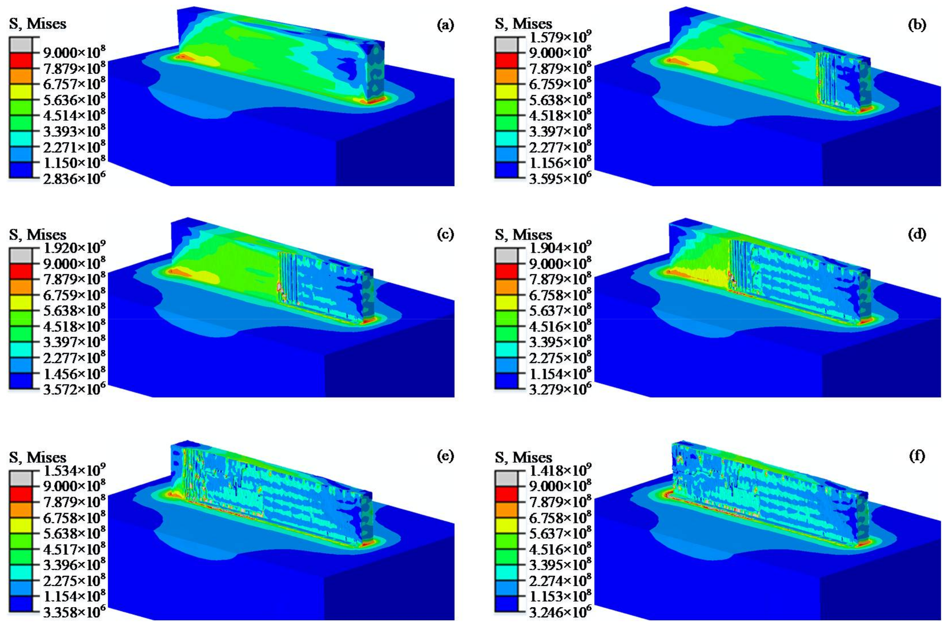
Figure 3 shows the cloud maps of stress field distribution at different times during milling; 0 s in the figure is the stress field cloud map after the additive manufacturing cools for 900 s. As seen in Figure 3a, there are significant differences in stress states in different regions; the residual stresses in the central region are relatively stable and basically consistent, and the stress fluctuations are large in the two regions of the start and end points of the laser heat source. The maximum residual stress is concentrated at the intersection of the cladding layer and the substrate. These results are due mainly to the thermal end effect [22]. As seen in Figure 3b–f, as milling progresses, the Von Mises values of the thin-walled pieces are significantly reduced, and at the same time, the distribution of residual stress in thin-walled parts is changed. At the initial moment, the sedimentary layer as a whole is in a pull stress state; as the cutting process progresses, and with the gradual removal of sedimentary surface materials, the pull stress that remains on the surface of the sediment layer caused by the additive manufacturing process decreases or even becomes pressure stress.
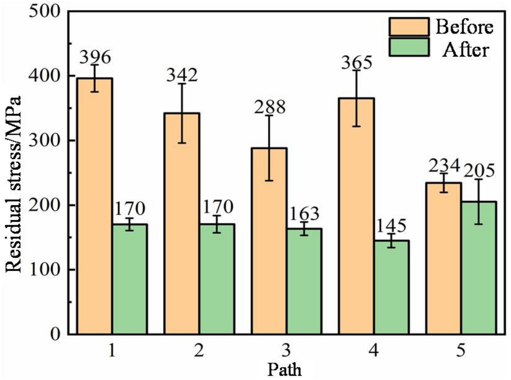
For studying the distribution of residual stress better, this study selects five paths from the bottom up at equal intervals in the cutting stability area of the machining surface and selects 20 nodes at equal intervals in each path. Residual stress values are collected for each node based on the path selected, and the collected residual stresses are calculated and averaged to obtain the residual stress for each path.
As shown in Figure 4, with the other parameter conditions unchanged, the milling speed vc is set to 140 m/min and the radial cutting depth ae is set to 0.3mm; then, the difference between the residual stress of the milling surface and the original forming surface is determined. It can be found that the maximum pull stress of the original face reaches 396 MPa, with the minimum being 234 MPa. After milling, the maximum pull stress is 205 MPa, and the minimum is 145 MPa; compared with the original surface residual pull stress, this represents a decrease of about 47% on average, showing a great reduction. At the same time, it can be found that after milling, the standard deviation of residual stresses throughout the surface is reduced; this can be explained by the fact that residual stress distribution is more uniform after milling and its anisotropy improves considerably.
Cutting temperature is an important variable to be monitored during milling. Figure 5 shows the comparison of the peak temperature of the tool tip during the processing of forged parts and additive manufacturing Ti6Al4V titanium alloy at different milling speeds. As can be seen from the figure, at different milling speeds, the cutting peak temperature of additive manufacturing Ti6Al4V titanium alloy is higher than that of forging Ti6Al4V parts, and when the milling speed increases, the milling temperature increases accordingly. Under the same processing conditions, compared with the forging, the cutting peak temperature of the additive manufacturing Ti6Al4V titanium alloy milling model is increased by about 26.2%.
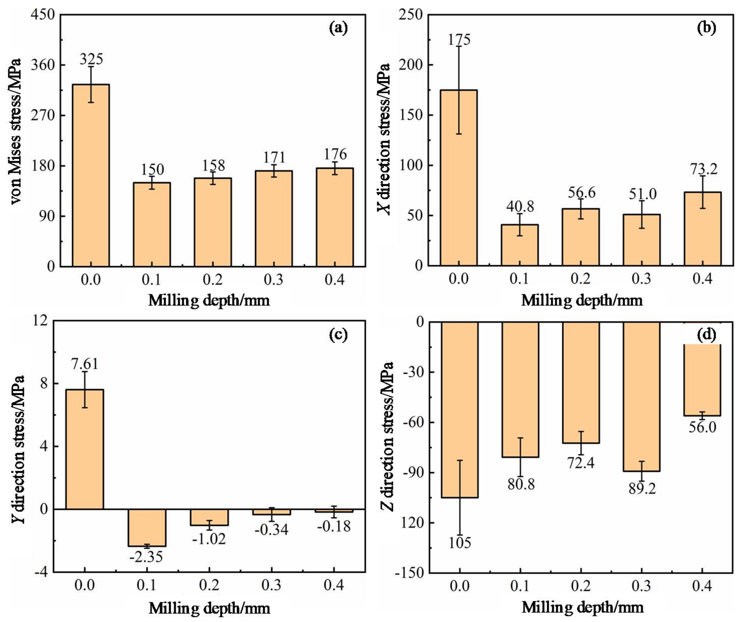
Figure 6 compares the residual stress changes of milling surfaces at different milling depths, with other parameters as constant and considering a milling depth of 0mm as the size of the residual stress of the original face. Figure 6a presents a comparison of Mises stress; it shows that the maximum pull stress of the original face is 325 MPa after milling and the maximum tensile stress is 176 MPa. Where the milling depth is 0.1 mm, the residual stress drop is the largest, reduced by approximately 54%. By observing the influence of milling depth on surface residual stress, it can be found that the surface residual tensile stress increases as the depth of milling increases. As can be seen from Figure 6b–d, milling has a significant impact on surface X direction and Y direction stresses, with the largest decreases being 77% and 131%, respectively. The effect on Z direction stress is weak, with the biggest drop being about 47%. At the same time, the X direction, Y direction and Z direction stresses of the milling surfaces as a whole show the trend of gradually decreasing the pull stress as the milling depth increases towards the pressure stress.
The initial temperature has a significant effect on the milling performance of titanium alloys. In the composite manufacturing process of adding and subtracting materials, the additive and subtractive processing alternate with each other; this results in the subtractive processing being performed in a high-temperature environment. Therefore, laser melting is studied. Wire additive manufacturing Ti6Al4V titanium alloy deposits have important guiding significance for the milling performance under hot, dry milling conditions. Figure 7 shows the residual stress under different initial temperatures and milling speeds. Figure 7a shows the equivalent Mises stress comparison of the milling surface. It can be found that when the initial temperature increases, the milling surface residual stress decreases gradually. As the initial temperature increases from room temperature to 400 °C, the maximum value of the milling surface average equivalent Mises stress drops from 122 MPa to 90 MPa, an average drop of about 26%. In Figure 7b, the residual stress in the X direction of the milling surface gradually decreases with an increase in the initial temperature. When the initial temperature increases from room temperature to 400 °C, the stress in the X direction of the milling surface decreases by 136.5% on average and the X direction residual tensile stress is greatly reduced, which can effectively reduce the risk of cracks and other defects in the additive part perpendicular to the X direction.
At the same time, as seen in Figure 7b, the milling speed has a significant influence on the directional stress. As the milling speed increases, the X direction stress gradually decreases or even becomes a compressive stress. As seen in Figure 7c, the initial temperature and milling speed have little effect on the Y direction stress of the milling surface. Figure 7d shows the comparison of the Z direction stress of the milling surface. It can be seen from the figure that the initial temperature has little effect on the Z direction stress of the milling surface. When the initial temperature increases, the compressive stress increases accordingly. The milling speed has a remarkable effect on the Z direction stress. As the milling speed increases, the Z direction compressive stress of the milling surface gradually increases. It can be seen from the above that appropriately increasing the initial preheating temperature and increasing the milling speed are beneficial in reducing the residual stress and improving the surface quality of the workpiece.

3.2. Model Validity Verification

To prove the validity of the model, it needs to be verified with the experimental results. Figure 8 displays the comparison between simulation data and experiment involving milling force variation [32]. From the change curve, it can be found that the milling force change trend during the simulation process and the results are basically consistent with the experimental data, which indirectly proves the validity of the model.

4. Conclusions

This study established a laser-fuse-increase material manufacturing 3D finite element model for milling titanium alloy using titanium alloy material manufacturing and milling process coupling. The material parts were considered with regard to the initial residual stress and temperature factors affecting the performance of milling, making the simulation more realistic. The cutting depth, milling speed, and other factors were analyzed to determine material manufacturing titanium alloy milling performance, the following conclusions were drawn:
(1)
Milling processes change the distribution state of residual stress in the cladding layer, which can reduce the tensile stress generated by additive manufacturing processes and even change it into compressive stress. Meanwhile, the residual stress distribution on the surface of the milling layer is more uniform, and the anisotropy is greatly improved. The equivalent Mises stress is reduced by 47% on average compared with that of the original forming surface.
(2)
At different milling speeds, the milling peak temperature of additive manufacturing parts is higher than that of forging parts, and the milling temperature gradually increases when the milling speed increases. Under the same processing conditions, the milling peak temperature of the additive manufacturing Ti6Al4V titanium alloy milling model increases by about 26.2%.
(3)
The residual stress on the milling surface decreases with an increase in the initial temperature. When the initial temperature increases from room temperature to 400 °C, the maximum Mises stress of the milling surface decreases by 26% on average, the X direction stress decreases by 136.5% on average, and the residual tensile stress decreases significantly.

Author Contributions

Z.R.: Conceptualization, Formal analysis, Writing-original draft, Writing-review & editing. X.Z.: Formal analysis. Y.W.: Visualization. Z.L. (Zhuhong Li): Software. Z.L. (Zhen Liu): Investigation. All authors have read and agreed to the published version of the manuscript.

Funding

This research was funded by National Key Research and Development Program Funded Project, grant number 2017YFB1103700.

Institutional Review Board Statement

Not applicable.

Informed Consent Statement

Not applicable.

Acknowledgments

The project is supported by National key R & D Program Funding (2017YFB1103700).

Conflicts of Interest

The authors declare no conflict of interest.

Nomenclature

SLMSelective laser melting
EBMElectron beam melted
DMLSDirect metal laser sintering
J-CJohnson-Cook constitutive model
AInitial yield stress
BStrain hardening parameter
CStrain rate hardening parameter
nHardening index
mThermal softening index
ε ˙ Equivalent plastic strain rate
ε ˙ 0 Reference strain rate
TrAmbient temperature
TmTi6Al4V melting point
τfFriction stress
μFriction coefficient
τsUltimate shear stress of the material
σnNormal stress on the contact surface
Δ ε p ¯ Equivalent plastic strain coefficient increment
ε p ¯ f Equivalent strain when the material fails
ε 0 ˙ ¯ Reference strain rate
σmAverage normal stress
ε ¯ Equivalent stress
vcMilling speed
aeCutting depth

References

  1. Zhang, Q.S.; Li, C.G.; Li, S.; Sui, S.; Wang, E.T. Research status and prospect of laser additive manufacturing technology for titanium alloy. Hot Work. Tech. 2018, 47, 21–24. [Google Scholar]
  2. Aremu, A.; Ashcroft, I.; Wildman, R.; Hague, R.; Tuck, C.; Brackett, D. The effects of bidirectional evolutionary structural optimization parameters on an industrial designed component for additive manufacture. Proc. Ins. Mech. Eng. 2013, 227, 794–807. [Google Scholar] [CrossRef]
  3. Maskery, I.; Aremu, A.; Simonelli, M.; Tuck, C.; Wildman, R.; Ashcroft, I.; Hague, R. Mechanical properties of Ti-6Al-4V selectively laser melted parts with body-centred-cubic lattices of varying cell size. Exp. Mech. 2015, 55, 1261–1272. [Google Scholar] [CrossRef] [Green Version]
  4. Yang, J.D.; Liu, R.H. Research development of 3D printing for large complex metal parts. Ordnan. Ind. Auto. 2017, 36, 8–12. [Google Scholar]
  5. Mok, S.H.; Bi, G.; Folkes, J.; Pashby, I. Deposition of Ti-6Al-4V using a high power diode laser and wire, Part I: Investigation on the process characteristics. Surf. Coat. Tech. 2008, 202, 3933–3939. [Google Scholar] [CrossRef]
  6. Pimenov, D.Y.; Mia, M.; Gupta, M.K.; Machado, A.R.; Tomaz, Í.V.; Sarikaya, M.; Wojciechowski, S.; Mikolajczyk, T.; Kapłonek, W. Improvement of machinability of Ti and its alloys using cooling-lubrication techniques: A review and future prospect. J. Mater. Res. Technol. 2021, 11, 719–753. [Google Scholar] [CrossRef]
  7. Syed, A.K.; Zhang, X.; Davis, A.E.; Kennedy, J.R.; Martina, F.; Ding, J.; Williams, S.; Prangnell, P.B. Effect of deposition strategies on fatigue crack growth behaviour of wire + arc additive manufactured titanium alloy Ti–6Al–4V. Mater. Sci. Eng. A 2021, 814, 1–12. [Google Scholar] [CrossRef]
  8. Chen, Y.; Chen, H.; Jiang, Y.S.; Wang, Q.; Wu, Y.; Xiong, J.; Dong, S.Y. Research progress in stress and deformation control in laser additive manufacturing for high-performance metals. J. Mater. Eng. 2019, 47, 1–10. [Google Scholar]
  9. Rodrigues, T.A.; Duarte, V.; Miranda, R.M.; Santos, T.G.; Oliveira, J.P. Current Status and Perspectives on Wire and Arc Additive Manufacturing (WAAM). Materials 2019, 12, 1121. [Google Scholar] [CrossRef] [Green Version]
  10. Ke, L.; Yin, J.; Zhu, H.; Peng, G.; Sun, J.; Chen, C.; Wang, G.; Li, Z.; Zeng, X. Numerical simulation of stress evolution of thin-wall titanium parts fabricated by selective laser melting. Acta Metall. Sin. 2020, 56, 374–384. [Google Scholar]
  11. Xiong, X.H.; Zhang, H.O.; Wang, G.L. Metal direct prototyping by using hybrid plasma deposition and milling. J. Mater. Process. Tech. 2009, 209, 124–130. [Google Scholar] [CrossRef]
  12. Lu, Z.; Tian, H.; Chen, S.; Li, F. Review on precision control technologies of additive manufacturing hybrid subtractive process. Acta Metall. Sin. 2020, 56, 83–98. [Google Scholar]
  13. Dong, Y.W.; Zhao, Q.; Li, X.L. The key technology and development of the compound processing of adding and reducing materials. MW Met. Cut. 2016, 13, 7–12. [Google Scholar]
  14. Du, W.; Bai, Q.; Zhang, B. A novel method for additive/subtractive hybrid manufacturing of metallic parts. In Proceedings of the 44th North American Manufacturing Research Conference, Virginia Polytechnic & State University, Blacksburg, VA, USA, 27 June–1 July 2016; pp. 1018–1030. [Google Scholar]
  15. Zhang, Y.J.; Song, B.; Zhao, X.; Zhang, L.C.; Wei, Q.S.; Shi, Y.S. Aisi 420 stainless steel fabricated by laser selective melting additive and machining: Evolution of surface roughness and residual stress. J. Mech. Eng. 2018, 54, 170–178. [Google Scholar] [CrossRef]
  16. Lopes, J.; Machado, C.M.; Duarte, V.R.; Rodrigues, T.A.; Santos, T.G.; Oliveira, J. Effect of milling parameters on HSLA steel parts produced by Wire and Arc Additive Manufacturing (WAAM). J. Manuf. Process. 2020, 59, 739–749. [Google Scholar] [CrossRef]
  17. Bordin, A.; Imbrogno, S.; Rotella, G.; Bruschi, S.; Ghiotti, A.; Umbrello, D. Finite element simulation of semi-finishing turning of electron beam melted Ti6Al4V under dry and cryogenic cooling. In Proceedings of the 15th CIRP Conference on Modelling of Machining Operations, Karlsruhe, Germany, 11–12 June 2015; pp. 551–556. [Google Scholar]
  18. Imbrogno, S.; Rinaldi, S.; Raso, A.; Bordin, A.; Bruschi, S.; Umbrello, D. 3D FE simulation of semi-finishing machining of Ti6Al4V additively manufactured by direct metal laser sintering. In Proceedings of the 21st International ESAFORM Conference on Material Forming, Palermo, Italy, 23–25 April 2018; pp. 1–6. [Google Scholar]
  19. Bordin, A.; Bruschi, S.; Ghiotti, A.; Bucciotti, F.; Facchini, L. Comparison between wrought and EBM Ti6Al4V machinability characteristics. In Proceedings of the 17th Conference of the European-Scientific-Association-on-Material-Forming, Espoo, Finland, 7–9 May 2014; pp. 1186–1193. [Google Scholar]
  20. Shunmugavel, M.; Polishetty, A.; Goldberg, M.; Singh, R.; Littlefair, G. A comparative study of mechanical properties and machinability of wrought and additive manufactured (selective laser melting) titanium alloy-Ti-6Al-4V. Rapid Prototyp. J. 2017, 23, 1051–1056. [Google Scholar] [CrossRef]
  21. Milton, S.; Morandeau, A.; Chalon, F.; Leroy, R. Influence of finish machining on the surface integrity of Ti6Al4V produced by selective laser melting. Proc. CIRP 2016, 45, 127–130. [Google Scholar] [CrossRef] [Green Version]
  22. Polishetty, A.; Shunmugavel, M.; Goldberg, M.; Littlefair, G.; Singh, R.K. Cutting force and surface finish analysis of machining additive manufactured titanium alloy Ti-6A1-4V. Proc. Manuf. 2017, 7, 284–289. [Google Scholar]
  23. Johnson, G.R.; Cook, W.H. A constitutive model and data for metals subjected to large strains, high rates and high temperatures. In Proceedings of the Seventh International Symposium on Ballistics, The Hague, The Netherlands, 1 January 1983; pp. 541–547. [Google Scholar]
  24. Johnson, G.R.; Cook, W.H. Fracture characteristics of three metals subjected to various strains, strain rates, temperatures and pressures. Eng. Fract. Mech. 1985, 21, 31–48. [Google Scholar] [CrossRef]
  25. Li, Y.F.; Zeng, X.G.; Liao, Y. Thermal-viscoplastic constitutive relation of Ti-6Al-4V alloy and numerical simulation by modified Johnson-Cook modal. Chin. J. Nonferr. Metal. 2017, 27, 1419–1425. [Google Scholar]
  26. Wu, H.B.; Zhang, S.J. 3D FEM simulation of milling process for titanium alloy Ti-6Al-4V. Int. J. Adv. Manuf. Tech. 2014, 71, 1319–1326. [Google Scholar] [CrossRef]
  27. Wang, Z.X.; Tian, X.G.; Gan, C.; Wei, B.H. Dynamic mechanical behavior of U75V steel under uniaxial compression and its modified J-C constitutive model. Trans. Mater. Heat Treat. 2019, 40, 156–164. [Google Scholar]
  28. Liu, Z. Numerical Simulation of Additive Manufacturing and Milling Performance of Titanium Alloy Laser Fuse. Master’s Thesis, Northeastern University, Shenyang, China, 2020. [Google Scholar]
  29. Ozel, T. The influence of friction models on finite element simulation of machining. Int. J. Mach. Tools Manuf. 2006, 46, 518–530. [Google Scholar] [CrossRef]
  30. Mackerle, J. Finite element analysis and simulation of machining: A bibliography (1976–1996). J. Mater. Process. Technol. 1999, 86, 17–44. [Google Scholar] [CrossRef] [Green Version]
  31. Pratap, T.; Patea, K.; Dyakonov, A.A. Modeling cutting force in micro-milling of Ti-6Al-4V titanium alloy. Proc. Eng. 2015, 129, 134–139. [Google Scholar] [CrossRef] [Green Version]
  32. Wang, H.X.; Xu, T.; Yang, J. Finite element simulation of titanium alloy milling process. Mech. Drive 2012, 36, 33–37. [Google Scholar]
Figure 1. 3D finite element model meshing.
Applsci 11 04813 g001
Figure 2. Stress field cloud diagram during thin-walled part forming: (a) the first floor ends; (b) the two floor ends; (c) the three floor ends; (d) the four floor ends; (e) the five floor ends.
Applsci 11 04813 g002
Figure 3. Stress cloud at different times during the milling process: (a) 0 s; (b) 0.037 s; (c) 0.074 s; (d) 0.111 s; (e) 0.148 s; (f) 0.185 s.
Applsci 11 04813 g003
Figure 4. Residual stress on milled surface and residual stress on original forming surface.
Applsci 11 04813 g004
Figure 5. Cutting temperature of forged and additive Ti6Al4V at different milling speeds.
Applsci 11 04813 g005
Figure 6. Residual stress of milling surface and original forming surface under different milling depths: (a) von Mises stress; (b) X direction stress; (c) Y direction stress; (d) Z direction stress.
Applsci 11 04813 g006
Figure 7. Residual stress of milling surface under different initial temperatures and milling speeds: (a) von Mises stress; (b) X direction stress; (c) Y direction stress; (d) Z direction stress.
Applsci 11 04813 g007
Figure 8. Comparison between simulation data and experiment involving milling force variation.
Applsci 11 04813 g008
Table 1. Johnson-Cook constitutive model parameters of Ti6Al4V titanium alloy.
MaterialA(MPa)B(MPa)nmC
Ti6Al4V10007800.471.020.033
Table 2. Chemical composition of Ti6Al4V titanium alloy (mass fraction, wt%).
Chemical ElementAlSiFeVCONTi
wt%5.40.150.303.4111.00.150.15Bal
Table 3. Tool material performance parameters.
Modulus of Elasticity (MPa)Poisson’s RatioCoefficient of Linear Expansion (°C)Specific Heat (J/kg·°C)Coefficient of Thermal Conductivity (W/m·°C)
6.4 × 1050.224.5 × 10−622075.4
Table 4. Ti6Al4V titanium alloy material damage failure parameters.
D1D2D3D4D5TmT0
−0.090.25−0.50.0143.871668 °C20 °C
Publisher’s Note: MDPI stays neutral with regard to jurisdictional claims in published maps and institutional affiliations.