Abstract
Efforts to enhance thermal efficiency of turbines by increasing the turbine inlet temperature have been further accelerated by the introduction of 3D printing to turbine components as complex cooling geometry can be implemented using this technique. However, as opposed to the properties of materials fabricated by conventional methods, the properties of materials manufactured by 3D printing are not isotropic. In this study, we analyzed the anisotropic thermal conductivity of nickel-based superalloy CM247LC manufactured by selective laser melting (SLM). We found that as the density decreases, so does the thermal conductivity. In addition, the anisotropy in thermal conductivity is more pronounced at lower densities. It was confirmed that the samples manufactured with low energy density have the same electron thermal conductivity with respect to the orientation, but the lattice thermal conductivity was about 16.5% higher in the in-plane direction than in the cross-plane direction. This difference in anisotropic lattice thermal conductivity is proportional to the difference in square root of elastic modulus. We found that ellipsoidal pores contributed to a direction-dependent elastic modulus, resulting in anisotropy in thermal conductivity. The results of this study should be beneficial not only for designing next-generation gas turbines, but also for any system produced by 3D printing.
1. Introduction
To increase the efficiency of gas turbines used in the industry, the turbine inlet temperature must be high [1]. Therefore, the turbine must be able to withstand a temperature high enough to accommodate the turbine inlet temperature. A material for turbine components that can be used at high operating temperatures is a nickel-based superalloy. Superalloys have been developed as a method of increasing temperature acceptance through various chemical compositions and casting methods [2,3,4]. In addition, research on film cooling technology that can increase the acceptance temperature is also being con-ducted. Film cooling technology is used as a method to prevent overheating of turbine components [5]. The film cooling hole consists of a large number of small diameters [6]. Since it is difficult to implement the design of the film cooling hole in the casting method, various studies on the manufacturing method have been carried out [7,8].
Although it is difficult to fabricate turbine components with a good cooling mechanism using the conventional casting method, additive manufacturing (AM) can overcome this limitation. Among AM technologies, selective laser melting (SLM) is a technology that partially melts a powder to create a desired shape [9]. The advantage of SLM is that it can produce structures with complex shapes, such as thin walls or small holes, with the same mechanical properties as those obtained via conventional manufacturing methods. SLM technology not only can create complex shapes but can also produce special shapes that cannot be manufactured by conventional casting methods [10].
Various studies are being conducted on the mechanical properties of materials made with SLM. In materials manufactured using SLM, the anisotropy that occurs due to the effect of the growth of grains and the pores generated inside according to the AM method also affects the mechanical properties. Yadroitsev et al. [11] found that the difference in elastic modulus, which is 1.5 times higher in the in-plane direction than in the cross-plane direction, and anisotropy occurs due to defects along the building direction using the nickel-based superalloy Inconel 625. Liu et al. [12] showed that the mechanical properties vary according to the building direction because the energy density of the SLM affects the grain growth using the nickel-based superalloy Inconel 718. Vilaro et al. [13] investigated that columnar grain growth of nickel-based superalloy Nimonic 263 affects difference in orientation of mechanical properties such as ductility and elastic modulus. In addition, Joguet et al. [14] conducted the Co28Cr6Mo alloy and showed a higher elastic modulus in the in-plane direction than in the cross-plane direction because pores prevented the growth of columnar grains.
Studies on the thermal properties of materials manufactured with SLM were also conducted. Alkahari et al. [15] found that the effective thermal conductivity is affected by the diameter of the metal powder, and that the thermal conductivity decreases as the porosity increases. Zhou et al. [16] demonstrated that the thermal conductivity of the Cu–Ni–Si alloy is higher in the cross-plane direction than in the in-plane due to the difference in scattering at the grain boundary. Strumza et al. [17] observed anisotropic thermal conductivity along the cross-plane and in-plane direction of AlSi10Mg materials owing to the texture and pore distribution. In addition, they observed the increase in thermal properties after heat treatment. Furthermore, Kim et al. [18] studied the thermal conductivity of AlSi10MG with changing polar angle, scan speed, and hatch spacing of the building direction. From this study, they confirmed that the directions of the melt pool and the cellular structure caused a change in thermal conductivity according to the polar angle. In addition, they found that the cell size influences the thermal conductivity due to the change in energy density of the laser during synthesis.
High thermal conductivity of superalloys is known to enable effective cooling and lower thermal stress to improve the lifespan of turbine components [19,20]. Superalloys with low thermal conductivity have the disadvantage of being damaged by temperature gradients and thermal stresses during turbine operation [21]. Understanding the thermal properties is necessary to calculate the heat transfer that occurs in many engineering situations [22], and to calculate the heat transfer simulation with accurate data [23,24]. In order to replace the material manufactured by the casting method with the material of the 3D printing manufacturing method, it is necessary to study the manufacturing conditions and anisotropy of thermal properties as well as mechanical properties. The turbine blades and vanes with complex thermal designs that were previously not achievable using conventional casting methods can now be manufactured by 3D printing. Consequently, further increase in the turbine inlet temperature becomes possible as complicated, yet heat-dissipation-friendly, geometries can be fabricated, leading to an enhancement in thermal efficiency of the turbine.
In this study, thermal properties of the nickel-based superalloy CM247LC manufactured by the SLM method, which is used as a material for turbine blades and vanes of gas turbines, were investigated to understand how they differ from those of CM247LC grown using conventional methods, i.e., directional solidification, polycrystalline, and single-crystalline material. In order to study the difference in density and anisotropy that occurs from the SLM method, the thermal conductivity of the prepared samples was measured by varying the control parameters such as laser power, scan speed, and layer thickness. Changes in thermal conductivity and anisotropy caused by additive manufacturing conditions were analyzed through the observation of the microstructure of the manufactured material.
2. Experimental Procedure
CM247LC powder was procured from Carpenter Additive Co., with particle sizes ranging from 15 µm to 45 µm. The chemical composition of CM247LC is identical to that of casting CM247LC by measuring powders via X-ray fluorescence (XRF, S8 Tiger, Bruker, Karlsruhe, Germany) [25]. We used an EOS M290 (EOS, Krailling, Germany) laser powder bed fusion (L-PBF) machine for SLM. The scan speed, laser power, and layer thickness were used as parameters to characterize the thermal conductivity, as shown in Figure 1. SLM was carried out using an Yb fiber laser. To prevent oxidation, a low oxygen level was maintained in the working environment using argon gas with flow rate of 20 m3/h. The SLM machine controls the laser power, scan speed, layer thickness, and hatch spacing to fabricate samples. The laser power represents the intensity of the Yb fiber laser, the scan speed is the rate at which the powder is melted using a laser in one layer, the layer thickness denotes the layer of the powder to be melted, and the hatch spacing is the distance between layers. Samples were prepared using laser powers of 100 W, 150 W, and 200 W; scan speeds of 1200 mm/s and 1800 mm/s; and layer thicknesses of 20 µm, 25 µm, and 30 µm. A scanning rotation angle of 67° was used to minimize defects caused by thermal residual stress [26]. The cross-plane direction is parallel to the building direction, and the in-plane direction is perpendicular to the stacking direction. We compared the differences in anisotropic thermal conductivity by measuring the microstructure, thermal conductivity, and electrical conductivity in the cross-plane and in-plane directions.

Figure 1.
Schematic of parameters for SLM and property measurement direction.
X-ray diffraction (XRD) spectra were obtained using high-resolution XRD (SmartLab, Rigaku, Tokyo, Japan) with CuKα radiation. Measurements were performed in the 2θ range of 20–80° with a step size of 0.02° at room temperature.
Three density measurement methods are commonly used in SLM: Archimedes’ method, microstructure analysis, and X-ray scanning [27]. Archimedes’ method is fast and easy to use. It is also accurate and repeatable at low density. Microstructure analysis involves determining the relative density by analyzing pores based on a scanning electron microscope (SEM, IT-500HR, JEOL, Tokyo, Japan) or optical microscope (OM, Olympus, Tokyo, Japan). SEM or OM analysis programs calculate partial areas, and therefore not all cross-sections are represented. Because the program measures a random part, the relative density varies depending on the magnification at low density. X-ray scanning can derive the density by analyzing the distribution of pores inside a material in three dimensions. The density may vary depending on the X-ray scan resolution. In this study, we used Archimedes’ method, which allows reliable results to be obtained repeatedly regardless of density. In addition, to observe the morphology and grain size, the samples were etched in 2% nitric acid for a few minutes. An OM was used to characterize the microstructure.
To characterize the anisotropy in thermal conductivity according to the building direction of the sample, the samples were prepared in the cross-plane and in-plane directions. The cross-plane direction is parallel to the building direction, and the in-plane direction is perpendicular to the building direction. The temperature-dependent thermal diffusivity was measured using a laser flash apparatus (LFA 457 MicroFlash, NETZSCH, Selb, Germany) under a nitrogen environment from 100 °C to 1100 °C at 100 °C intervals. In addition, the electrical conductivities were measured using an electrical resistance measurement system (ZEM-3, ULVAC-RIKO, Yokohama, Japan) to decompose the total thermal conductivity into electronic and lattice thermal conductivities.
3. Results
Figure 2 shows XRD spectra of the CM247LC powder, directional solidification [28], and SLM samples. Consistent with findings by Divya et al. [29] and Kim et al. [28], a face-centered cubic (FCC) γ + γ’ phase was detected in all samples. The samples all have the same peak corresponding to the crystallographic planes of (111), (200), and (220), but the intensity varies depending on the control parameters. It can be seen that the directional solidification casting shows a high peak in plane (200) due to the grains grown in the casting direction. In the case of SLM manufacturing, it is possible to estimate how much grain growth has occurred depending on the control parameter.
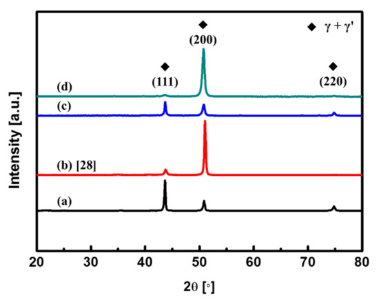
Figure 2.
CM247LC XRD data; (a) powder, (b) directional solidification [28], (c) laser power 100 W, scan speed 1800 mm/s, layer thickness 30 µm, and (d) laser power 150 W, scan speed 1200 mm/s, layer thickness 20 µm.
The growth parameters, i.e., laser power (W), P, scan speed (mm/s), v, and layer thickness (mm), t, can be combined into the volumetric energy density (J/mm3) using the following equation [30]:
where H is the hatch spacing (mm). Figure 3 shows the density with respect to the energy density. The dotted box denotes the density at the same energy density. It can be seen that the density varies even at the same energy density. The blue area indicates a density decrease with an increase in layer thickness at 100 W of laser power and a scan speed of 1200 mm/s. The green area indicates a density decrease with an increase in layer thickness at 100 W of laser power and a scan speed of 1800 mm/s. Overall, the density decreases as the layer thickness and scan speed increase. At the same energy density, laser power has the greatest effect on density, followed by layer thickness and scan speed. It is known that the porosity of the cross-section decreases as the density increases, regardless of the building direction, as shown in studies regarding the correlation between energy density and porosity [31,32].
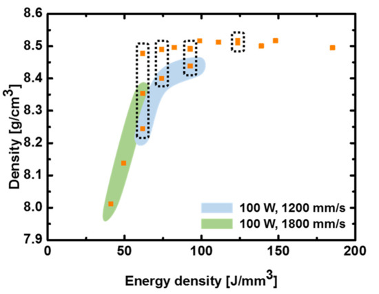
Figure 3.
Dependence of CM247LC density on energy density.
The thermal conductivity of CM247LC can be decomposed into the effects of electrons and lattice vibrations, based on kinetic theory:
where k is thermal conductivity (W/m-K), L is the Lorenz number (WΩ/K2), σ is the electrical conductivity (S/m), T is the absolute temperature (K), Cv is the volumetric specific heat (J/m3-K), ν is the speed of sound (m/s), and l is the mean free path (m). Figure 4 shows the electrical and lattice thermal conductivities of a sample fabricated using a laser power, scan speed, and layer thickness of 100 W, 1800 mm/s, and 30 µm, respectively. The electronic thermal conductivity of the nickel-based superalloy CM247LC dominates the lattice thermal conductivity. The electronic thermal conductivity, derived from the measured electrical conductivity, does not vary with temperature in either the cross-plane or in-plane direction. However, the lattice thermal conductivity is higher in the in-plane direction than it is in the cross-plane direction.
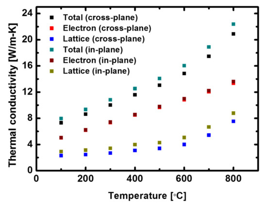
Figure 4.
Dependence of cross-plane and in-plane electronic and lattice thermal conductivities on temperature.
Figure 5a shows the cross-plane and in-plane thermal conductivities according to the density at 800 °C, clearly showing that as the density increases, so does the thermal conductivity. A decrease in thermal conductivity with porosity is typical [33]. However, the thermal conductivities in the cross-plane and in-plane directions differ, especially at low density. At low densities, the in-plane direction shows higher thermal conductivity than that in the cross-plane direction. The thermal conductivity at 800 °C is shown in Figure 5b. Similarly, the electronic thermal conductivity in the two directions is the same, but the lattice thermal conductivity is approximately 16.5% higher in the in-plane direction. The electronic thermal conductivities in the cross-plane and in-plane direction are comparable, but the lattice thermal conductivity is higher in the in-plane direction. The speed of sound, ν, in Equation (2) can be expressed as follows:

Figure 5.
(a) Dependence of thermal conductivity in the cross-plane and in-plane directions on density and (b) electronic and lattice contributions to cross-plane and in-plane thermal conductivities.
The speed of sound of the lattice thermal conductivity shown in Equation (2) is the square root of the ratio of the elastic modulus (GPa), E, and density (kg/m3), ρ, as shown in Equation (3). Samples manufactured by SLM with metallic powder have a higher elastic modulus in the in-plane direction compared with the cross-plane direction [11]. In the manufacturing process, thermal stress accumulates as a result of rapid heating and cooling [34], or flat pores are generated because of the low energy density [35,36] between layers. These defects result in a higher elastic modulus in the in-plane direction than in the cross-plane direction [11,14]. The anisotropy according to direction varies depending on the porosity, but the in-plane direction has an elastic modulus that is approximately 50% higher than that in the cross-plane direction [11]. Therefore, the thermal conductivity is higher in the in-plane direction because it is proportional to the square root of the elastic modulus.
To analyze the change in thermal conductivity caused by the difference in density, the microstructure of the cross-section was observed. Figure 6a–d show cross-plane and in-plane OM images of high- and low-density samples. Figure 6a,b show the cross-plane and in-plane cross-sections from a high-density sample fabricated with a laser power of 150 W, 1200 mm/s scan speed, and 20 µm layer thickness. Figure 6c,d show the cross-plane and in-plane cross-sections from a low-density sample fabricated with a laser power of 100 W, 1800 mm/s scan speed, and 30 µm layer thickness. It can be seen that the difference in density reflects the influence of defects and pores generated inside the material. Defects and pores can be classified into three groups: pores, melting-related defects, and cracks [37]. In Figure 6, blue circles indicate that unmelted particles are present in large pores. This is because the particles did not melt, as the low laser power could not supply sufficient heat. These pores are formed because of the low energy density [35]. The black dotted line in Figure 6d represents the process of generating irregular-shaped pores. The mechanism of irregular pore generation is shown in a schematic diagram in Figure 6e. Gas is trapped in the pores during manufacturing. Irregular pores are formed between the layers because of the gas contraction force and gravity during rapid heating and cooling [36]. The ellipsoid pores expand because of the high gas temperature. As the temperature decreases, the gas in the pores contracts, leading to the formation of flat pores as a result of gravity. Therefore, the pores have a flat shape in the in-plane direction. Furthermore, the pores marked with red circles in Figure 6 are the result of an incomplete melting process. The pores can reduce the density, but they also interfere with grain growth. As shown in Figure 6d, the grain growth is limited by the presence of pores, and thus the grains are smaller than those shown in Figure 6b.
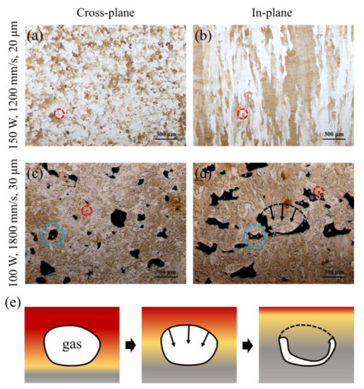
Figure 6.
OM images of sample fabricated with laser power 150 W, scan speed 1200 mm/s, and layer thickness 20 µm (a) cross-plane and (b) in-plane; images of sample fabricated with laser power 100 W, scan speed 1800 mm/s, and layer thickness 30 µm (c) cross-plane and (d) in-plane; (e) schematic diagram of irregular pore generation.
4. Conclusions
In this study, the thermal conductivity of the nickel-based superalloy CM247LC manufactured by the SLM method was analyzed. Samples with different densities were fabricated by controlling the parameters of SLM. The density of a sample is proportional to the energy density and is proportional to the thermal conductivity. We found there exists an anisotropy in lattice thermal conductivity owing to the low density of a sample. At low density, pores trapped in the gas form various shapes because of the insufficient energy density. During the manufacturing process, the contraction of gas with rapid heating and cooling causes the pores to change into irregular shapes, resulting in anisotropy in the elastic modulus. The lattice thermal conductivity and elastic modulus are greater in the in-plane direction than they are in the cross-plane direction because the lattice thermal conductivity is proportional to the square root of the elastic modulus, and the difference in the lattice thermal conductivity is proportional to difference in the square root of the elastic modulus (16.5%). Our finding can be useful in designing a device using additive manufacturing where thermal properties are important.
Author Contributions
Conceptualization, K.K. and W.K.; methodology, K.K. and W.K.; investigation, K.K and W.K; resources, J.K., E.P., and N.K.; writing—original draft preparation, K.K. and W.K.; writing—review and editing, K.K and W.K.; supervision, W.K. All authors have read and agreed to the published version of the manuscript.
Funding
This work was supported by the Korea Institute of Energy Technology Evaluation and Planning (KETEP) grant funded by the Korea government (MOTIE) (20193310100030, Development of high efficient F-class gas turbine hot component by controlling and applying Design for Additive Manufacturing).
Institutional Review Board Statement
Not applicable.
Informed Consent Statement
Not applicable.
Data Availability Statement
Not applicable.
Conflicts of Interest
The authors declare no conflict of interest.
References
- Rahman, M.M.; Ibrahim, T.K.; Abdalla, A.N. Thermodynamic performance analysis of gas-turbine power-plant. Int. J. Phys. Sci. 2011, 6, 3539–3550. [Google Scholar]
- Chumsty, N.; Heyes, A. Jet Propulsion, 3rd ed.; Cambridge University Press: New York, NY, USA, 2003. [Google Scholar]
- Reed, R.C. The Superalloys: Fundamentals and Applications, 1st ed.; Cambridge University Press: New York, NY, USA, 2008. [Google Scholar]
- Wee, S.; Do, J.; Kim, K.; Lee, C.; Seok, C.; Choi, B.-G.; Choi, Y.; Kim, W. Review on mechanical thermal properties of superalloys and thermal barrier coating used in gas turbines. Appl. Sci. 2020, 10, 5476. [Google Scholar] [CrossRef]
- Yao, Y.; Zhang, J.-Z.; Tan, X.-M. Numerical study of film cooling from converging slot-hole on a gas turbine suction side. Int. Commun. Heat Mass Transf. 2014, 52, 61–72. [Google Scholar] [CrossRef]
- Fang, X.; Qu, N.; Li, H.; Zhu, D. Enhancement of insulation coating durability in electrochemical drilling. Int. J. Adv. Manuf. Technol. 2013, 68, 2005–2013. [Google Scholar] [CrossRef]
- Zhang, Y.; Xu, Z.; Zhu, Y.; Zhu, D. Machining of a film-cooling hole in a single-crystal superalloy by high-speed electrochemical discharge drilling. Chin. J. Aeronaut. 2016, 29, 560–570. [Google Scholar] [CrossRef]
- Zhang, Y.; Xu, Z.; Zhu, D.; Qu, N.; Zhu, Y. Drilling of film cooling holes by a EDM/ECM in situ combined process using internal and side flushing of tubular electrode. Int. J. Adv. Manuf. Technol. 2016, 83, 505–517. [Google Scholar] [CrossRef]
- Yap, C.Y.; Chua, C.K.; Dong, Z.L.; Liu, Z.H.; Zhang, D.Q.; Loh, L.E.; Sing, S.L. Review of selective laser melting: Materials and applications. Appl. Phys. Rev. 2015, 2, 041101. [Google Scholar] [CrossRef]
- Sotov, A.V.; Agapovichev, A.V.; Smelov, V.G.; Kokareva, V.V.; Dmitrieva, M.O.; Melnikov, A.A.; Golanov, S.P.; Anurov, Y.M. Investigation of the IN-738 superalloy microstructure and mechanical properties for the manufacturing of gas turbine engine nozzle guide vane by selective laser melting. Int. J. Adv. Manuf. Technol. 2020, 107, 2525–2535. [Google Scholar] [CrossRef]
- Yadroitsev, I.; Thivillon, L.; Bertrand, P.; Smurov, I. Strategy of manufacturing components with designed internal structure by selective laser melting of metallic powder. Appl. Surf. Sci. 2007, 254, 980–983. [Google Scholar] [CrossRef]
- Liu, S.Y.; Li, H.Q.; Qin, C.X.; Zong, R.; Fang, X.Y. The effect of energy density on texture and mechanical anisotropy in selective laser melted Inconel 718. Mater. Des. 2020, 191, 108642. [Google Scholar] [CrossRef]
- Vilaro, T.; Colin, C.; Bartout, J.-D.; Nazé, L.; Sennour, M. Microstructural and mechanical approaches of the selective laser melting process applied to a nickel-base superalloy. Mater. Sci. Eng. A 2012, 534, 446–451. [Google Scholar] [CrossRef]
- Joguet, D.; Danlos, Y.; Bolot, R.; Montavon, G.; Coddet, C. Modeling and measurement of the effective young modulus of porous biomedical materials manufactured via SLM. Key Eng. Mater. 2014, 606, 125–128. [Google Scholar] [CrossRef]
- Alkahari, M.R.; Furumoto, T.; Ueda, T.; Hosokawa, A.; Tanaka, R.; Abdul Aziz, M.S. Thermal conductivity of metal powder and consolidated material fabricated via selective laser melting. Key Eng. Mater. 2012, 244–249. [Google Scholar] [CrossRef]
- Zhou, Y.; Zeng, X.; Yang, Z.; Wu, H. Effect of crystallographic texture on thermal anisotropy of selective laser melted Cu-2.4 Ni-0.7 Si alloy. J. Alloys. Compd. 2018, 743, 258–261. [Google Scholar] [CrossRef]
- Strumza, E.; Yeheskel, O.; Hayun, S. The effect of texture on the anisotropy of thermophysical properties of additively manufactured AlSi10Mg. Additive Manuf. 2019, 29, 100762. [Google Scholar] [CrossRef]
- Kim, M.-S. Effects of processing parameters of selective laser melting process on thermal conductivity of AlSi10Mg alloy. Materials 2021, 14, 2410. [Google Scholar] [CrossRef]
- Zieliñska, M.; Yavorska, M.; Porêba, M.; Sieniawski, J. Thermal properties of cast nickel based superalloys. Arch. Mater. Sci. Eng. 2010, 44, 35–38. [Google Scholar]
- Terada, Y.; Ohkubo, K.; Miura, S.; Sanchez, J.M.; Mohri, T. Thermal conductivity and thermal expansion of Ir3X (X= Ti, Zr, Hf, V, Nb, Ta) compounds for high-temperature applications. Mater. Chem. Phys. 2003, 80, 385–390. [Google Scholar] [CrossRef]
- Przeliorz, R.; Piątkowski, J. Thermophysical properties of nickel-based cast superalloys. Metalurgija 2015, 54, 543–546. [Google Scholar]
- Ormerod, J.; Taylor, R.; Edwards, R. Thermal diffusivity of cast irons. Met. Technol. 1978, 5, 109–113. [Google Scholar] [CrossRef]
- Brooks, R.; Day, A.; Mills, K.; Quested, P. Physical property measurements for the mathematical modeling of fluid flow in solidification processes. Int. J. Thermophys. 1997, 18, 471–480. [Google Scholar] [CrossRef]
- Matsushita, T.; Fecht, H.-J.; Wunderlich, R.K.; Egry, I.; Seetharaman, S. Studies of the thermophysical properties of commercial CMSX-4 alloy. J. Chem. Eng. Date 2009, 54, 2584–2592. [Google Scholar] [CrossRef]
- Harris, K.; Erickson, G.L.; Schwer, R.E. MAR M 247 derivations—CM 247 LC DS alloy, CMSX single crystal alloys, properties and performance. Superalloys 1984, 1984, 221–230. [Google Scholar]
- Ali, H.; Ghadbeigi, H.; Mumtaz, K. Effect of scanning strategies on residual stress and mechanical properties of selective laser melted Ti6Al4V. Mater. Sci. Eng A 2018, 712, 175–187. [Google Scholar] [CrossRef]
- Spierings, A.B.; Schneider, M.; Eggenberger, R. Comparison of density measurement techniques for additive manufactured metallic parts. Rapid Prototyp. J. 2011, 17, 380–386. [Google Scholar] [CrossRef]
- Kim, K.; Kim, W. Thermophysical properties of nickel-based superalloy CM247LC. Trans. Korean Soc. Mech. Eng. B 2020, 44, 619–625. [Google Scholar] [CrossRef]
- Divya, V.D.; Muñoz-Moreno, R.; Messé, O.M.D.M.; Barnard, J.S.; Baker, S.; Illston, T.; Stone, H.J. Microstructure of selective laser melted CM247LC nickel-based superalloy and its evolution through heat treatment. Mater. Charact. 2016, 114, 62–74. [Google Scholar] [CrossRef]
- Kurzynowski, T.; Stopyra, W.; Gruber, K.; Ziółkowski, G.; Kuźnicka, B.; Chlebus, E. Effect of scanning and support strategies on relative density of SLM-ed H13 steel in relation to specimen size. Materials 2019, 12, 239. [Google Scholar] [CrossRef]
- Gu, H.; Gong, H.; Pal, D.; Rafi, K.; Starr, T.; Stucker, B. Influences of energy density on porosity and microstructure of selective laser melted 17-4PH stainless steel. In Proceedings of the 2013 Solid Freeform Fabrication Symposium, Austin, TX, USA, 12–14 August 2013. [Google Scholar]
- Sallica-Leva, E.; Jardini, A.L.; Fogagnolo, J.B. Microstructure and mechanical behavior of porous Ti–6Al–4V parts obtained by selective laser melting. J. Mech. Behav. Biomed. Mater. 2013, 26, 98–108. [Google Scholar] [CrossRef]
- Koh, J.C.Y.; Fortini, A. Thermal Conductivity And Electrical Resistivity of Porous Material; NASA: Washington, DC, USA, 1971. [Google Scholar]
- Kruth, J.-P.; Froyen, L.; Van Vaerenbergh, J.; Mercelis, P.; Rombouts, M.; Lauwers, B. Selective laser melting of iron-based powder. J. Mater. Process. Technol. 2004, 149, 616–622. [Google Scholar] [CrossRef]
- Ronneberg, T.; Davies, C.M.; Hooper, P.A. Revealing relationships between porosity, microstructure and mechanical properties of laser powder bed fusion 316L stainless steel through heat treatment. Mater. Des. 2020, 189, 108481. [Google Scholar] [CrossRef]
- Dong, S.; Zhang, X.; Ma, F.; Jiang, J.; Yang, W.; Lin, Z. Research on metallurgical bonding of selective laser melted AlSi10Mg alloy. Mater. Res. Express 2020, 7, 025801. [Google Scholar] [CrossRef]
- Sola, A.; Nouri, A. Microstructural porosity in additive manufacturing: The formation and detection of pores in metal parts fabricated by powder bed fusion. J. Adv. Manuf. Process. 2019, 1, e10021. [Google Scholar] [CrossRef]


Publisher’s Note: MDPI stays neutral with regard to jurisdictional claims in published maps and institutional affiliations. |
© 2021 by the authors. Licensee MDPI, Basel, Switzerland. This article is an open access article distributed under the terms and conditions of the Creative Commons Attribution (CC BY) license (https://creativecommons.org/licenses/by/4.0/).