Article

Development of a Drone’s Vibration, Shock, and Atmospheric Profiles

1
Department of Packaging Science, Rochester Institute of Technology, Rochester, NY 14623, USA
2
Patent Examination Cooperation, Jiangsu Center of the Patent Office, Suzhou 215000, China
3
Department of Packaging Engineering, Jiangnan University, Wuxi 214122, China
*
Author to whom correspondence should be addressed.
Appl. Sci. 2021, 11(11), 5176; https://doi.org/10.3390/app11115176
Submission received: 9 April 2021 / Revised: 18 May 2021 / Accepted: 25 May 2021 / Published: 2 June 2021
(This article belongs to the Section Acoustics and Vibrations)

Abstract

:
Technological advances in unmanned aerial vehicles (UAVs) have made it possible to employ drone deliveries for packaged products, but currently no standards of practice are available to qualify packaged products traveling through this distribution channel. This research proposes a methodology to collect field data from a UAV to develop simulation techniques for use with package testing equipment. This project utilized data recorders to measure the vibration, shock, and atmospheric field data on two models of the DJI drones. The root mean square G value (Grms), the power spectral density (PSD), maximum G-values and shock response spectrum, and atmospheric data were reported in this study. The study found that the general shape of the PSD profile of the drones differed from the PSD air profiles of the aircraft. The overall recorded Grms levels of the drones were also significantly higher than those of the published air profile of the aircraft. Moreover, the study found that the drone’s in-flight vibration intensities in the horizontal level were consistently higher than those in the vertical direction. The major sources of vibration and shock in both drones’ models originated from the two-propeller rotations. Shocks recorded during the flight reached 14 G, took place in the horizontal plane with the drone accelerating as opposed to the vertical plane where the drone is landing.

1. Introduction

Technological advances in unmanned aerial vehicles (UAV) have made it possible to operate drone deliveries of packaged products. Since 2011, the drone firm Matternet has used drones to deliver medical supplies and specimens to countries around the world, including Switzerland, Haiti, and the Dominican Republic [1]. In 2017, Matternet and Mercedes-Benz collaborated and used vans as rolling distribution hubs (drone-van combos) for a three-week aerial package delivery to deliver goods for local e-tailer Siroop in a Swiss city [2]. JD.com in China plans to build 185 drone ports in China’s mountainous southwest region to cut logistical costs [3]. The logistics affiliate of e-commerce titan Alibaba, Cainiao, recently used drones to deliver tea leaves from mountain slopes directly to processing centers below, shortening the time to market [4]. The Icelandic company, Aha, which launched a limited trial with Israeli company Flytrex in 2019, will phase in further drones over the next two years [5]. UPS and DHL also conducted trial runs for residential delivery [6].
Similar to other transport means, the drone and its payload experience vibration, shock, and atmospheric hazards during the take-off, in-flight, and landing [7]. The vibration and shock to the drones are usually associated with two sources. The first is the structural vibration and shock resulting from periodic excitation from drone motors and propeller blades [8]. Throttling up or down can increase or reduce the periodic excitation frequency. The second is the interaction between the drone quadcopter/propellers and the airflow, which is also variable as it depends on air turbulence and weather patterns. The atmospheric hazards are due to the atmospheric environment acting upon the goods without shielding. Understanding these input vibrations as well as the generated shock and atmospheric conditions will help packaging engineers better understand these hazards and provide sufficient protective design for various goods delivered by the drone.
In contrast to the numerous measurements on the truck [9,10,11] and rail [12,13] environment garnered within the last 30 years, only a few major research studies have been conducted in the field of aircraft environment to better characterize its vibration, shock and atmospheric profile. The Forest Products Laboratory’s (FPL) General Technical Report 22 is an early report conducted on aircraft vibration during taxi, takeoff/landing, and cruise mode [14]. The study indicated that the excitation frequencies are highly dependent on the type of aircraft engines such as turbojet and turboprop whereas the amplitudes are more dependent on the flight modes (takeoff, climb, cruise, and landing). For example, the engine of turboprop had an excitation frequency of 68 Hz for C-130 aircraft and 48 Hz for C-133 aircraft. However, the data included in the FPL report did not indicate overall Grms (overall energy of random vibration) levels for the different aircraft types. In 1988, Trost conducted a research study to measure an aircraft’s acceleration, involving mechanical stresses during air cargo shipment [15]. The recording device was mounted on the pallet in the air cargo. The measured maximum G-level ranged from 0.05 G to 0.16 G during cruising of the flight and 0.20 G to 0.42 G during the taxiing, takeoff, touchdown, descent and landing. The Amgen Air PSD profile was developed by mounting the data recorder to the floor of a unit load device (ULD) inside of a jet engine aircraft [16]. The resulting PSD published had an overall Grms level of 0.017 Grms level. The collected vibration was not measured directly from air cargo but from the ULD.
In order to develop a vibration profile as direct input, Dunno and Batt [17] mounted the recorder in the cargo area next to the wing of the aircraft and recorded the in-flight vibrations of a turbo propeller aircraft. The overall in-flight Grms value measured during 30 individual flights was 0.155, which is significantly higher than that of the Amgen study. The maximum acceleration recorded was 2.11 G, which occurred predominantly during the ascent and descent of the aircraft. The typical steady-state vibration did not exceed an intensity of 0.2 g. Figure 1 created by Dunno illustrated the comparison in air profiles between Amgen’s study, Dunno’s study, ASTM D 4169 Air (level II), and ISTA 4AB [18,19]. Although the time compression, from the actual field time to the laboratory testing time, was already factored in in both ASTM D 4169 level II and ISTA 4AB air profiles, both Dunno’s and Amgen studies exhibited a significantly lower vibration intensity compared to the ASTM D 4169 air assurance Level II and the ISTA 4AB. Currently, no drone vibration, shock, and atmospheric data specifically linked to the delivery of packaged products have been published.
The aim of this research is to capture and characterize the drone’s input vibration and shock, as well as the in-flight atmospheric condition, which could be utilized by packaging engineers to develop a test method for drone delivery. The vibration and shock profiles obtained from this research are intended to be applied in simulations for in-flight vibrations and shock of the drone chassis in a laboratory environment. The in-flight atmospheric profile was intended for preconditioning for the laboratory simulation.

2. Materials and Methods

2.1. Drones and the Data Logger

The DJI Matrice 600 Pro and DJI Matrice 100 (SZ DJI Technology Co., Ltd., Shenzhen, Guangdong, China) were the two drones used for this research study. These drones were selected as they have similar payload capacity with multi-rotor configurations as compared to other drones currently being explored in the area of parcel delivery. Their specifications and capacities are shown in Table 1. Figure 2 illustrates the different drones and the locations in which the data loggers were rigidly mounted.
Pak-Track™ data loggers were utilized to capture triaxial vibration and shock, temperature, humidity, light, and pressure conditions (Rochester Institute of Technology, Rochester, NY, USA). Each drone was outfitted with two Pak-Track™ data loggers to understand and correlate the differences between the rigid chassis and potential compartment where the payload could be stored for transport. For the DJI Matrice 600 Pro, one data logger was rigidly mounted to the top platform, while the other was mounted above the frame of the payload. The DJI Matrice 100 had one data logger rigidly mounted to the top platform, and the other data logger was placed on the quadcopter frame. The orientation of the mounted sensors was such that the X-axis was the longitudinal (forward) direction of travel, Y-axis was the lateral direction of travel, and Z-axis was the vertical direction. The signal trigger sampling method was used for collecting all field data, meaning the data were recorded during an event when the data intensity exceeded a preset threshold. The signal trigger threshold levels are displayed in Table 2 and were selected to ensure only events of interest were collected. The vibration sampling frequency was set to 1600 Hz, and each sampled vibration period was determined to be 1.28 s for 2048 data points [20,21]. The flight time for the DJI Matrice 600 was approximately 60 min. The flight time for the DJI Matrice 100 was 10 min due to the limited flight capacity of the drone being 25 min of potential flight time. Figure 3 and Figure 4 show the flight path (dark line) of the two drones. The flight paths chosen were part of a study seeking to identify the potential of image collection for the detection of agricultural vegetation growth. The flight patterns and durations of service drones for delivery are likely to be much longer than collected here [22]. However, the research aimed to develop a methodology for which to generate test profiles based on field-measured data.

2.2. Characterization Methods

The vibration and shock data collected from data loggers were channeled into the software for calculating the consolidated PSD chart, Grms histogram, and shock response spectrum. The atmospheric data were plotted with timestamps.

2.2.1. Consolidated Vibration PSD Spectrum

The consolidated PSD charts combined all PSD plots of the recorded vibration events, without deletion or overwriting. Power spectral density (PSD) is measured vibration signals using the Fast Fourier Transform (FFT) algorithm, which represents the average intensity of the vibration [9]. Each consolidated PSD value on the consolidated PSD chart at a particular frequency was calculated from Equation (1), meaning that the combined PSD chart was created by consolidating the root mean square of PSD values at respective frequencies [13].
PSDconsolidated   ( frequency ) = PSD 1 2 + PSD 2 2 + PSD 3 2 + + PSD n 2 n
The root mean square G value (Grms) corresponds to the square root of the area under the PSD plot, which can be computed through the integration of the PSD curve. Grms represents the value of alternating vibration acceleration and its capability of vibration energy transfer.
Grms = Area   under   the   PSD   plot

2.2.2. Grms Histogram

While the PSD charts correlated the excitation frequencies and the PSD values, the Grms histogram represented the relationship between the numbers of events occurred and the respective Grms values. The Grms value in the histogram is calculated based on each of the individual PSD plots that are based on 2048 sampling points over 1.28 s. These histograms enabled the packaging engineers to develop the laboratory vibration profile with different assurance levels.

2.2.3. Shock Respond Spectrum (SRS)

The shock response spectrum is an effective tool for estimating the damage potential of a shock pulse to a structure. The shock response spectrum is calculated based on the acceleration time history. It assumes that an excitation is applied as base excitation, to an array of single-degree-of-freedom (SDOF) systems [23]. The two main parameters of the SDOF system, which are specifying free oscillation, are the structure’s natural frequency and damping [24]. For a normalized value of the damping parameter Q, typically assumed as 5% (Q = 10), the response is dependent on the natural frequency of the system [23]. The dependence of the peak values on the natural frequency in the form of a diagram is called Shock Response Spectrum (SRS) [24].

3. Results and Discussion

Overall, a significant amount of high vibration G-value was recorded that was near or over the limit of the accelerometer’s measuring range of ±4 G. For the DJI Matrice 600 Pro, 40% and 72% of the vibration events exhibited G-values at or above 4 G for the bottom and top data logger, respectively. For the DJI Matrice 100, 76% and 65% of the vibration events exhibited G-values at or above 4 G for the bottom and top data logger, respectively. When comparing the timestamp of high vibration G-values from the data logger with the drone control platform, it is evident that the high vibration G-values occurred mostly at the points of turning. Figure 5 shows the exemplary vibration data and PSD chart at the moment of turning.

3.1. Consolidated PSD Vibration Spectrum

The PSD plots from the data loggers show that the shapes of the curves were similar to each other for each drone. The vibration intensities at the higher frequency range are generally higher than those observed in the lower frequency region (Figure 6 and Figure 7). All of the PSD plots are characterized by three distinctive vibration regions. Region 1 (1.56 to 10 Hz) shows the interaction between the quadcopter frame (around 10 Hz and below) and the airflow caused by the drone’s rotating and moving around of the quadcopter (around 1.56 Hz and above). Region 2 (10–70 Hz) represents the RPM of the motor shaft and 2-blade rotations between the minimum stable throttle to 50–60% of the throttle. The vibration frequency of the motor shaft is the RPM divided by 60. For example, a 600 RPM will have a 10 Hz vibration frequency, and the 2-blade vibration frequency is twice that of the motor shaft. Region 3 (70–230 Hz) the excitation frequencies were a function of the motors and 2-blade propeller at the high rotations per minute (RPM). The motor shaft generated vibration frequency can be estimated using (Motor RPM)/60 Hz. The 2-blade propellers’ corresponding vibration frequency can be estimated using (Motor RPM)/30 Hz.
Comparing the PSD spectra of the DJI Matrice 600 Pro to that of the DJI Matrice 100, the shapes are similar in the higher frequency range, reflecting the characteristics of the motor and two-blade propeller structure. However, they differ in the lower frequency regions for all three directions on the vibration intensities. The PSD plot of the DJI Matrice 100 showed higher vibration intensities in the low-frequency region than that of the DJI 600 Pro at the horizontal level, alluding to the fact that the DJI Matrice 100 is more susceptible to fluttering—a dynamic instability of flight vehicle associated with the interaction of aerodynamic, elastic, and inertial forces [25]—and rotation by airflow due to its relatively light weight. In contrast, the DJI Matrice 600 Pro exhibited higher vibration intensities in low frequency only in the vertical direction.
Table 3 and Table 4 illustrated the major frequencies and PSD breakpoints corresponding to Figure 6 and Figure 7. These were selected after smoothing the PSD curves and to allow for the ability to be used by vibration test systems to represent this type of package delivery method.

3.2. Grms Values

Table 5 illustrates the maximum Grms and the Grms values range where 68% of the vibration events fall in. The overall recorded Grms levels of the drones were significantly higher than those in the published air profile of the aircraft [17,26]. The DJI Matrice 600 Pro tends to have a higher vibration Grms than DJI Matrice 100, especially in X-direction. The Grms recorded in the horizontal level are higher in general than that in the vertical direction.
The Grms histogram indicated that overall Grms values are close to the normal distribution (Figure 8 and Figure 9).
Overall, the major vibration sources are inherited from the high-frequency motor and structure and not from the interaction between the drone and the airflow characterized by lower vibration frequency. This is different from the truck and railroad profiles where the high vibration intensity comes mainly from the interaction between the road and suspension to the products.

3.3. Shock

For DJI Matrice 600 Pro, there was a total of 39 shock events recorded by the top data logger in the Y direction during the flight, with an averaged G-value of 5.57 ± 0.9. The intensity of a given shock is characterized by its acceleration level (amplitude), and the length of time (duration) over which the shock takes place [27]. Shock events are either positive or negative because of the orientation of the impact event. No shock events were recorded in the X and Z directions. The Y direction is in line with the axis of the two arms (Figure 2). On the other hand, three shock events were detected by the data logger on the platform above the payload in the Z direction, its averaged G-value recorded was 6.40 ± 0.9. No shocks were recorded in the X and Y directions by this data logger. The buffer between the motor and platform is effective in filtering out most shock events in the horizontal level caused by motors.
For DJI Matrice 100, a total of 128 shock events in the Y direction were recorded by the data logger installed on the frame during the flight (Bottom data logger). The average shock value was 7.80 ± 1.6. The top data logger recorded eight shock events in the Z direction. The averaged G-value was 6.16 ± 0.5. There were no big major shocks recorded during the takeoff and landing for both drones in all three directions.
Table 6 revealed some of the major shocks above the average and their SRS frequencies. The shock frequencies corresponding to the peak values for both drones are between 171.85 Hz to 182.67 Hz, indicating the same shock response frequencies related to the two-propeller rotations across the two drones.
Figure 10 shows continuous shocks in the Y direction recorded by the bottom data logger on the DJI Matrice 100. Figure 11 illustrates the SRS spectrum of the number 9 event in Figure 10. The 12.8 G in the Y direction occurred at 182.01 Hz, which could be the effect of the 2-blade propeller’s structure frequency (Motor RPM)/30 Hz, originating from the motor shaft frequency 91 Hz, (Motor RPM)/60. These values suggest that the aforementioned shocks are likely caused by the throttle jumps of the drone operator pilot. The quadcopter frame where the bottom data logger was located, connects all four arms of the propellers and directly receives the shock from the propellers when the throttle jumps occurred, whereas the top data logger had relative minimal shocks due to its location in the center of the drone, furthest from the propellers.

3.4. Atmospheric Data

Figure 12 displays the light, atmospheric pressure, temperature, and humidity data collected by the top data logger on DJI Matrice 600 Pro during the one-hour flight. Compared to bottom data loggers, the top data logger was exposed to open air, allowing for easier collection of data pertaining to light and atmospheric pressure. It should be noted that all atmospheric data experienced fluctuation within the one-hour flight due to the change of altitude. The fluctuation in atmospheric conditions within a short time is unique for the drone. Usually, if the air cargo is pressurized and temperature controlled, there will be no dramatic change in atmospheric conditions [28].

4. Conclusions

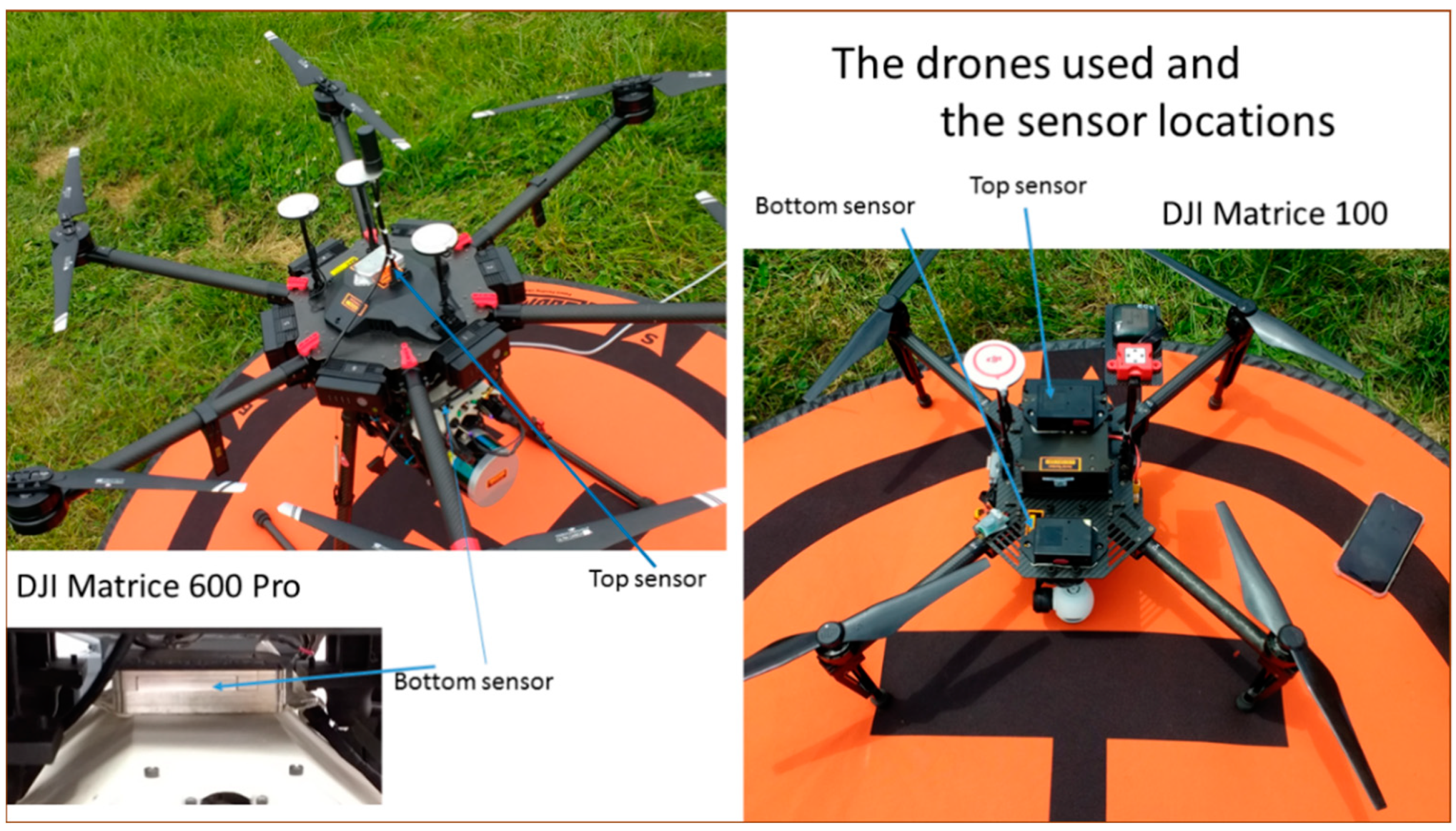
The general shape and vibration intensity of the PSD profiles of the two drones showed no similarities to those that are currently used for representing package delivery via air transport. However, the PSD profiles of the drones selected for this study were similar in their overall shape. They share the same range of exciting vibration frequencies caused by the motor and 2-blade propellers due to the similar propeller speeds, which ranged from the minimal frequency 40–70 Hz for keeping drone steady, to high Grms values in the 165–182 Hz range in which the drones were at cruising speed. Both PSD profiles also share similar patterns in lower frequency zones, for which the interaction between the drone and airflow is responsible. The interaction of the drone with airflow, in the form of bump and lurch, is characterized by low frequencies between about 1.56 to 10 Hz.
The overall recorded Grms levels of the drones were significantly higher than those currently published for package testing for air transport. The recorded Grms values range from 0.49 to 1.69 in the lateral direction and from 0.54 to 0.99 in the vertical direction. The larger size drone generally tended to have higher Grms values than the smaller drone, especially in the horizontal plane. Most of the high vibration Grms values took place at the turning point of the drones.
The motor and 2-propellers are also sources of the shocks at the horizontal level. These shock values can reach numbers as high up as 14 G. The throttle jumps of the drone were likely created by the significant horizontal impacts. In contrast, the vertical shock levels, originally thought to have the greatest severity, were significantly lower than horizontal impacts, even during landing.
Fluctuation of atmospheric data during the flight is unique to the drone and attention should be paid when considering what kind of products can be shipped out as all the atmospheric conditions were affected by the change in altitude.
The data collected by the data logger on the platform of the payload and the data logger on the quadcopter frame are the most relevant information that can be applied to simulate in-flight vibration and shock of the drone chassis in a laboratory environment. Data in Table 2 and Table 3 can be used to drive vibration test systems and results shown in Table 5 can be channeled into a shock tester for simulation. Future studies should involve additional trip destinations, utilization of different models of drones, as well as placing the data logger in different locations to develop test methods that could be used to evaluate packaged products traveling through this emerging delivery channel.

5. Recommendations

Based on the results from this project, the authors make the following recommendations:
  • As UAVs become more practical as a mode to deliver packages to consumers, further work to characterize this transport environment is critical for product and package engineers. The field measured levels can be incorporated into package test protocols that can be used to aid in the development of packaged product systems passing through this distribution network.
  • Further field measurement using actual products would aid in understanding the effects of this transport environment on product quality. The focus should be around areas related to vibration and shock response.

Author Contributions

Conceptualization, C.G.; methodology, C.G., K.D., L.Y., and L.-X.L.; software, M.A.S., C.G.; validation, C.G., K.D., L.Y., and L.-X.L.; formal analysis, M.A.S., C.G., and K.D.; data curation, C.G., M.A.S., K.D.; writing—original draft preparation, C.G., M.A.S., K.D., L.Y., L.-X.L.; writing—review and editing, C.G., K.D.; visualization, C.G., K.D.; supervision, C.G.; All authors have read and agreed to the published version of the manuscript.

Funding

This research received no external funding.

Institutional Review Board Statement

Not applicable.

Informed Consent Statement

Not applicable.

Data Availability Statement

The data presented in this study are available on request from the corresponding author.

Acknowledgments

The authors wish to thank Donald McKeown for his valuable contributions to this project.

Conflicts of Interest

The authors declare no conflict of interest.

References

  1. Turban, E.; Whiteside, J.; King, D.; Outland, J. Electronic Commerce Payment Systems and Order Fulfillment. In Introduction to Electronic Commerce and Social Commerce; Turban, E., Whiteside, J., King, D., Outland, J., Eds.; Springer Texts in Business and Economics; Springer International Publishing: Cham, Germany, 2017; pp. 331–380. ISBN 978-3-319-50091-1. [Google Scholar]
  2. Mercedes-Benz: Vans & Drones. Available online: https://www.mercedes-benz.com/en/vehicles/transporter/vans-drones-in-zurich/ (accessed on 2 February 2021).
  3. Chan, T.F. One of China’s Biggest Online Retailers Plans to Build Nearly 200 Drone Airports to Bring e-Commerce to Rural China. Available online: https://www.businessinsider.com/chinese-online-retailer-is-building-200-drone-airports-rural-china-2017-12 (accessed on 2 February 2021).
  4. Riley, C. Alibaba Is Using Drones to Deliver Tea. Available online: https://money.cnn.com/2015/02/04/technology/alibaba-delivery-drones/index.html (accessed on 2 February 2021).
  5. Iceland Expands Food Delivery by Drone in Reykjavik. BBC News. 13 June 2018. Available online: https://www.bbc.com/news/technology-44466353 (accessed on 1 April 2021).
  6. Heutger, M.; Kückelhaus, M. Unmanned Aerial Vehicles in Logistics: A DHL Perspective on Implications and Use Cases for the Logistics Industry; DHL Customer Solutions & Innovation: Troisdorf, Germany, 2014. [Google Scholar]
  7. Oakey, A.; Waters, T.; Zhu, W.; Royall, P.G.; Cherrett, T.; Courtney, P.; Majoe, D.; Jelev, N. Quantifying the Effects of Vibration on Medicines in Transit Caused by Fixed-Wing and Multi-Copter Drones. Drones 2021, 5, 22. [Google Scholar] [CrossRef]
  8. Verbeke, J.; Debruyne, S. Vibration analysis of a UAV multirotor frame. In Proceedings of the of ISMA 2016 International Conference on Noise and Vibration Engineering, Leuven, Belgium, 9–21 September 2016; pp. 2329–2337. [Google Scholar]
  9. Park, J.; Choi, S.; Jung, H.M. Measurement and Analysis of Vibration Levels for Truck Transport Environment in Korea. Appl. Sci. 2020, 10, 6754. [Google Scholar] [CrossRef]
  10. Singh, J.; Singh, S.P.; Joneson, E. Measurement and Analysis of US Truck Vibration for Leaf Spring and Air Ride Suspensions, and Development of Tests to Simulate These Conditions. Packag. Technol. Sci. 2006, 19, 309–323. [Google Scholar] [CrossRef]
  11. Singh, S.P.; Joneson, E.; Singh, J.; Grewal, G. Dynamic Analysis of Less-than-Truckload Shipments and Test Method to Simulate This Environment. Packag. Technol. Sci. 2008, 21, 453–466. [Google Scholar] [CrossRef] [Green Version]
  12. Böröcz, P.; Singh, S.P. Measurement and Analysis of Vibration Levels in Rail Transport in Central Europe. Packag. Technol. Sci. 2017, 30, 361–371. [Google Scholar] [CrossRef]
  13. Chonhenchob, V.; Singh, S.P.; Singh, J.J.; Sittipod, S.; Swasdee, D.; Pratheepthinthong, S. Measurement and Analysis of Truck and Rail Vibration Levels in Thailand. Packag. Technol. Sci. 2010, 23, 91–100. [Google Scholar] [CrossRef] [Green Version]
  14. Ostrem, F.E.; Godshall, W.D. An Assessment of the Common Carrier Shipping Environment; Department of Agriculture, Forest Service, Forest Products Laboratory: Madison, WI, USA, 1979. [Google Scholar]
  15. Trost, T. Mechanical Stresses on Products during Air Cargo Transportation. Packag. Technol. Sci. 1988, 1, 137–155. [Google Scholar] [CrossRef]
  16. Wallin, B. Developing a Random Vibration Profile Standard. In Proceedings of the 2007 IAPRI Symposium, Windsor, UK, 3–5 September 2007. [Google Scholar]
  17. Dunno, K.; Batt, G. Analysis of In-flight Vibration of a Twin-engine Turbo Propeller Aircraft. Packag. Technol. Sci. Int. J. 2009, 22, 479–485. [Google Scholar] [CrossRef]
  18. ASTM International. D4169-16 Standard Practice for Performance Testing of Shipping Containers and Systems; ASTM International: West Conshohocken, PA, USA, 2016. [Google Scholar]
  19. ISTA. Project 4AB: Packaged-Products for Shipment in Known Distribution Channels; ISTA: East Lansing, MI, USA, 2009. [Google Scholar]
  20. Ge, C.; Pan, L. Vibration Damage Rate Curves for Quantifying Abrasion of Printed Packaging in Accelerated Random Vibration Test. Packag. Technol. Sci. 2018, 31, 71–81. [Google Scholar] [CrossRef]
  21. Paternoster, A.; Vanlanduit, S.; Springael, J.; Braet, J. Measurement and Analysis of Vibration and Shock Levels for Truck Transport in Belgium with Respect to Packaged Beer during Transit. Food Packag. Shelf Life 2018, 15, 134–143. [Google Scholar] [CrossRef]
  22. Huang, H.; Savkin, A.V.; Huang, C. Scheduling of a Parcel Delivery System Consisting of an Aerial Drone Interacting with Public Transportation Vehicles. Sensors 2020, 20, 2045. [Google Scholar] [CrossRef] [PubMed] [Green Version]
  23. Irvine, T. An Introduction to the Shock Response Spectrum (Revision S). 2012. Available online: https://www.vibrationdata.com/tutorials2/srs_intr.pdf (accessed on 1 April 2021).
  24. Tuma, J.; Koci, P. Calculation of a Shock Response Spectrum. In Proceedings of the 2011 12th International Carpathian Control Conference (ICCC), Velke Karlovice, Czech Republic, 25–28 May 2011; pp. 404–409. [Google Scholar]
  25. Ansari, A.R.; Novinzadeh, A.R.B. Designing a Control System for an Airplane Wing Flutter Employing Gas Actuators. Int. J. Aerosp. Eng. 2017, 2017, 1–9. [Google Scholar] [CrossRef] [PubMed] [Green Version]
  26. Dunno, K. Analysis of In-Flight Vibration of a Single Engine Propeller Aircraft. Int. J. Adv. Packag. Technol. 2014, 2, 105–111. [Google Scholar] [CrossRef] [Green Version]
  27. Goodwin, D.; Young, D. Protective Packaging for Distribution; DEStech Publications, Inc.: Lancaster, PA, USA, 2011. [Google Scholar]
  28. Singh, S.P.; Singh, J.; Stallings, J.; Burgess, G.; Saha, K. Measurement and Analysis of Temperature and Pressure in High Altitude Air Shipments. Packag. Technol. Sci. 2010, 23, 35–46. [Google Scholar] [CrossRef] [Green Version]
Figure 1. Air vibration PSD profile comparison.
Applsci 11 05176 g001
Figure 2. The DJI Matrice 600 Pro and The DJI Matrice 100 and the data logger locations.
Applsci 11 05176 g002
Figure 3. Cruise route of the DJI Matrice 600 Pro.
Applsci 11 05176 g003
Figure 4. Cruise route of the DJI Matrice 100.
Applsci 11 05176 g004
Figure 5. Exemplary vibration events during the turning of the drone.
Applsci 11 05176 g005
Figure 6. Consolidated PSD profiles of the top and bottom part of the DJI Matrice 600 Pro.
Applsci 11 05176 g006
Figure 7. The consolidated PSD air profiles of the top and bottom part of the DJI Matrice 100.
Applsci 11 05176 g007
Figure 8. Vibration Grms histogram for DJI 600.
Applsci 11 05176 g008
Figure 9. Vibration Grms histogram for DJI 100.
Applsci 11 05176 g009
Figure 10. Exemplary shock data collected by the bottom data logger on the DJI Matrice 100.
Applsci 11 05176 g010
Figure 11. SRS spectrum of shock event number 9 from Figure 11.
Applsci 11 05176 g011
Figure 12. Exemplary atmospheric data collected by the bottom data logger on the DJI Matrice 600 Pro.
Applsci 11 05176 g012
Table 1. Specification of the DJI Matrice drones.
Model NameDJI Matrice 600 ProDJI Matrice 100
Number of rotors64
Drone Weight22.05 lbs. (10 kg)5.35 lbs. (2.43 kg)
Payload weight34.17 lbs. (15.5 kg)7.93 lbs. (3.6 kg)
Propellers2 Blade2 Blade
Motor modelDJI 6010DJI 3510
Table 2. Data logger recording parameters.
Event TypeEvent Trigger Threshold
Temperature26.7 °C
Humidity50% RH
Vibration0.09 g
Shock4.48 g
Pressure101 KPa
Light500 Clear
Table 3. Frequencies and PSD breakpoints for DJI Matrice 600 Pro.
Frequency and PSD breakpoints for DJI Matrice 600 Pro top
X-Axis (Lateral)Y-Axis (Longitudinal)Z-Axis (Vertical)
Frequency (Hz)PSD (g2/Hz)Frequency (Hz)PSD (g2/Hz)Frequency (Hz)PSD (g2/Hz)
1.560.0002641.560.0002911.560.000749
3.130.0003357.810.0004005.470.000921
77.340.00048114.060.00048313.280.001013
89.840.00186228.130.00033265.630.000442
96.090.00358771.880.00031978.130.002540
150.000.00575196.880.00349796.880.032923
164.000.060750145.310.026648167.970.021617
175.000.140900160.150.032923175.000.038123
179.680.165814178.130.030444210.940.002561
210.940.007295210.940.011054
Frequency and PSD breakpoints for DJI Matrice 600 Pro bottom
X-Axis (Lateral)Y-Axis (Longitudinal)Z-Axis (Vertical)
Frequency (Hz)PSD (g2/Hz)Frequency (Hz)PSD (g2/Hz)Frequency (Hz)PSD (g2/Hz)
6.250.0002516.250.0007083.1250.002264
10.160.00049711.720.0005099.3750.001788
21.880.00077321.090.00056420.310.001160
80.470.00179352.340.00113092.960.001107
97.660.01163399.230.004898110.940.001150
167.190.007783171.880.009151173.440.004891
178.130.017958180.470.017030178.130.006435
181.250.024818188.280.011457
210.940.001084
Table 4. Frequencies and PSD breakpoints for DJI Matrice 100.
Frequency and PSD breakpoints for DJI Matrice 100 top
X-Axis (Lateral)Y-Axis (Longitudinal)Z-Axis (Vertical)
Frequency (Hz)PSD (g2/Hz)Frequency (Hz)PSD (g2/Hz)Frequency (Hz)PSD (g2/Hz)
1.560.0001961.560.0000951.560.002401
7.030.0002039.380.0001726.250.001030
14.840.00028219.530.0002669.380.001658
19.530.00023627.340.00036044.530.001255
25.780.00033181.250.00133891.410.001667
72.660.00043296.880.002042117.970.002057
98.440.012128164.060.016571169.530.003886
165.630.024107 194.530.009995
189.840.013427
Frequency and PSD breakpoints for DJI Matrice 100 bottom
X-Axis (Lateral)Y-Axis (Longitudinal)Z-Axis (Vertical)
Frequency (Hz)PSD (g2/Hz)Frequency (Hz)PSD (g2/Hz)Frequency (Hz)PSD (g2/Hz)
3.130.0003771.560.0018201.560.000214
8.590.0005725.470.0019533.130.000316
60.150.00462219.530.0022659.380.000325
96.880.00580482.030.00265979.690.003400
161.720.058768120.310.002689100.780.004283
175.000.095141139.840.019277121.090.043357
185.150.029264144.530.017011136.720.021441
159.380.049592144.530.017361
167.190.034629175.000.056834
Table 5. Overall vibration Grms value and Grms values near 68%.
DroneDJI Matrice 600 ProDJI Matrice 100
Data loggerTopBottomTopBottom
AxisXYZXYZXYZXYZ
Overall Grms1.61.010.950.780.650.540.660.490.531.090.970.99
No. of events67.8%64.5%70.2%68.9%59.2%68.8%70.6%73.5%70.2%72.9%70.3%78.3%
Range of the Grms0.42–1.030.36–0.720.33–0.650.25–0.500.21–0.420.20–0.390.15–0.440.12–0.330.15–0.430.24–0.700.21–0.620.23–0.66
Table 6. Major shocks and their SRS frequencies.
DJI Matrice 600 Pro Shock Values above the Average
Max. XMax. YMax. ZLocation of Data LoggerSRS Frequency (Hz)
−3.20−7.043.84Top data logger171.85
−3.20−6.403.20Top data logger171.85
−3.20−7.043.84Top data logger182.01
−3.20−6.403.84Top data logger182.01
DJI Matrice 100 Pro shock values above the average
−2.56−12.80−3.20Bottom data logger182.67
−2.56−12.163.20Bottom data logger182.01
−4.48−14.083.84Bottom data logger171.85
−4.48−10.883.84Bottom data logger182.01
−3.20−10.883.84Bottom data logger182.01
−3.84−10.883.84Bottom data logger182.01
−3.84−10.243.84Bottom data logger171.85
−3.20−11.523.84Bottom data logger171.85
−3.20−10.243.84Bottom data logger182.01
−3.84−10.243.84Bottom data logger136.61
Publisher’s Note: MDPI stays neutral with regard to jurisdictional claims in published maps and institutional affiliations.

