1. Introduction
Stirred reactors with baffles are used in the chemical industry to obtain chemical products by mixing two or more components, [
1]. The quality of the final chemical product obtained inside the industrial reactor is influenced by the performance of the stirring mechanism that equips the reactor. For the industrial reactors operating with a liquid-solid mixture it is of great importance that the stirring mechanism ensures a homogenous dispersion of the solid particles inside the entire volume of liquid and to prevent the sedimentation of the solid particles on the lower cover of the reactor.
Using CFD for modelling the complex flow inside industrial reactors proves to be an efficient, time saving and tractable method to analyze the performances of the stirring mechanism that is present in the reactor. Many researchers have used different types of expert CFD codes (Fluent, CFX) [
2,
3,
4,
5,
6,
7,
8,
9] for investigating the multiphase flow inside stirred reactors. A part of the previous research focused on identifying the appropriate turbulent model to be used [
5,
6]. Another preoccupation of the researchers was to identify the best suitable model for modelling the solid suspension inside the liquid volume from the ones available in the expert CFD codes [
10,
11,
12,
13,
14,
15,
16,
17,
18,
19,
20].
Taking into consideration the results from [
10,
11,
12,
13,
14], the best suited model for our research was the RNG k-ε turbulence model, which allows sufficient accuracy of the turbulent quantities within a reasonable calculation time, and the Eulerian multiphase model for calculating the liquid–solid mixture.
This research paper represents the third paper from a series of three that investigate the performance of a new stirring mechanism from a baffle industrial reactor [
21,
22]. The main idea behind the three research papers is to develop a tractable and robust numerical approach for customized design and assessment of mixing impellers, beyond the rather classical approach of selecting on-the-shelf impellers based on empirical correlations. In the first paper [
21], we investigate the performances of the original stirring mechanism fitted with an impeller with two blades, that was initially designed to operate with a liquid-liquid combination. An extensive presentation of the numerical model and numerical set-up is presented in this paper. This type of impeller proves to be not appropriate for mixing a liquid–solid combination because there is a consistent amount of solid particles sedimented on the bottom of the reactor and a large share of the volume of liquid is depleted of solid particles. We designed a new impeller with three blades and with a smaller diameter than the original one and, in our second research paper [
22], we analysed the performance of the stirring mechanism fitted with the new impeller in the same position, regarding the bottom of the reactor, as the original impeller. The new impeller proved to have a better performance from the point of view of solid particle sedimentation, but it still cannot ensure a homogenous distribution of the solid particles in the entire volume of the liquid phase.
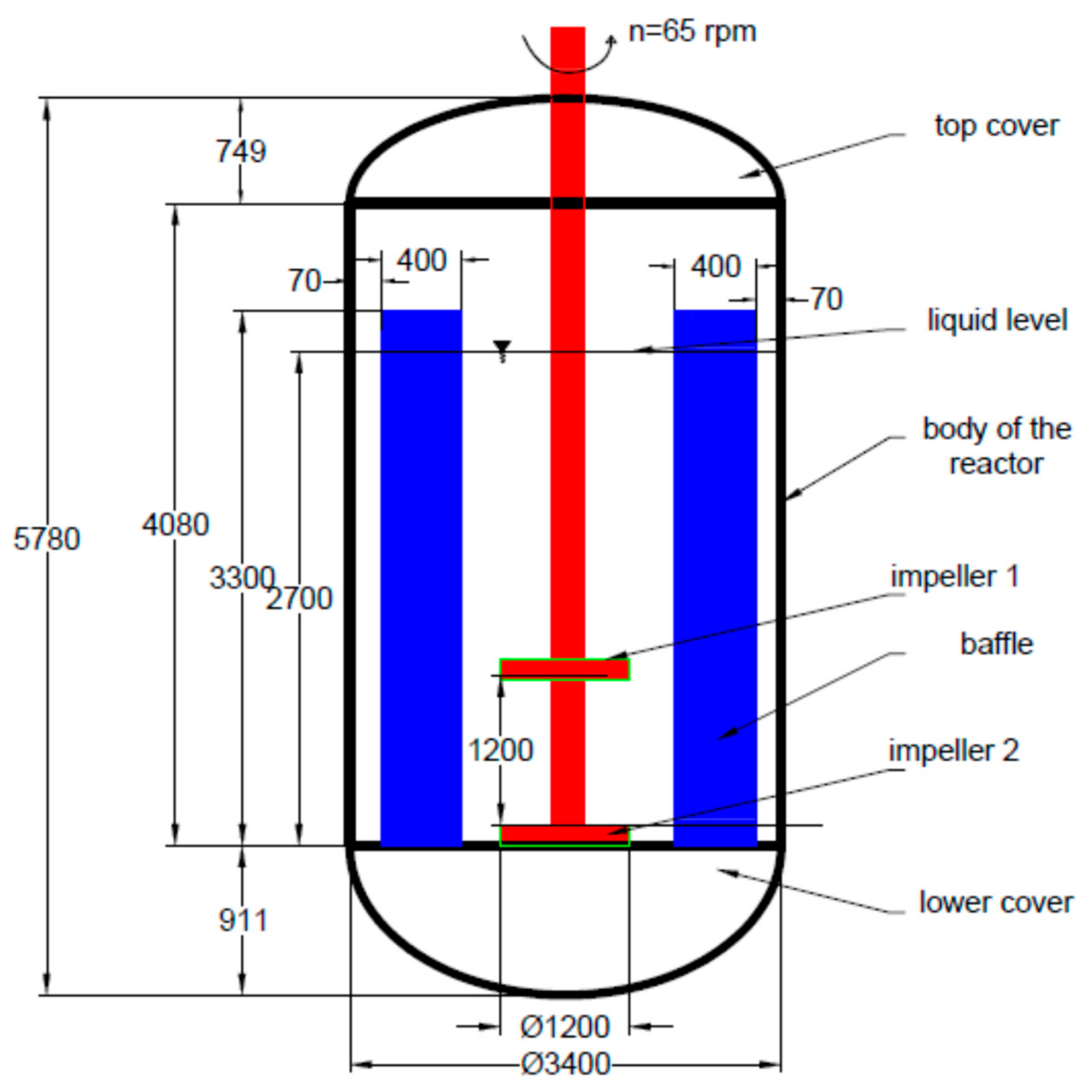
Since the results presented in the previous two papers indicate that the two solutions investigated did not ensure a proper dispersion of the solid particles in the volume of the liquid phase, in the current paper we analyse a new solution consisting in fitting on the existing stirring mechanism two new designed impellers operating in tandem. A schematic representation of the investigated stirred reactor is presented in
Figure 1, where the two new designed impellers are fitted on the stirring mechanism. The two impellers have three blades each and operate at the same rotational speed of 65 rpm. The lower impeller is positioned in the same place, regarding the lower cover of the reactor, as the original impeller. The upper impeller is positioned at a distance equal with the diameter of the impeller, regarding the position of the lower impeller, as suggested in [
1].
After analysing the results obtained from CFD simulation of the flow, from the point of view of the dispersion of the solid phase in the entire volume of the liquid phase and judging the hydrodynamic performance of the two impellers operating in tandem, a decision will be made if the new arrangement with two impellers in tandem will be implemented in the industrial reactor.
2. Numerical Methods
The Eulerian multiphase model is use for modelling the flow behaviour for each of the liquid and solid phases. This model is the most complex model, as it solves a set of momentum equations for each phase and is the most time-consuming model. For liquid-solid interaction we took into consideration only the drag force according to the Huilin–Gidaspow model and the air–liquid interaction employs the Schiller–Naumann model. We considered one dispersed phase, the solid particles, one continuous phase, the liquid, and above free surface we consider a volume of air. We did not apply surface compression and we did not include the effect of surface tension.
For simulating the turbulence effects, the RNG k-ε model with the dispersed option has been chosen. The dispersed turbulence model is the appropriate model when using the granular model.
The geometry of the industrial stirred reactor fitted with the two new designed impellers in tandem and the mesh was generated with the help of the software Gambit 2.4. The mesh of finite elements consists of approximately 0.94 million tetrahedral elements. As regards the mesh quality, we use hybrid tetrahedral/hexahedral mesh cells as recommended for such complex geometries [
2,
3]. In this study a good quality of mesh (skewness < 0.84) has been ensured throughout the computational domain. Although the mesh influence upon numerical results was not addressed and a larger mesh element number may generate more accurate results, the size of the mesh employed in this study may be assumed to be appropriate to compare the performances of the single and tandem impellers.
As in our previous research papers [
21,
22], we used the Sliding Mesh approach, and four fluid zones were defined: an inner rotating cylindrical volume centered on the two impellers and three other volumes containing the rest of the reactor and the baffles. The interface is located at equal distance from the blades of the two impellers and the inside edge of the baffles. An illustration of the domain and the mesh of the domain is given in
Figure 2, which shows that finer meshes have been used around the two impellers where the velocity spatial gradients are expected to be large. Good care was taken in keeping the same mesh dimensions between the rotating and the stationary interface to ensure a good exchange of the hydrodynamic quantities between the two zones during calculation. A “no-slip” condition is applied on all walls of the geometry.
Simulations of the turbulent multi-phase flow are then performed with the help of the commercial CFD code Ansys® Fluent, Release 16 using the RNG k-ε model. There are three working materials corresponding to the three phases: liquid with the density ρl = 690 kg∙m−3 and viscosity of 0.00023 kg/m∙s, powder with the density ρp = 1520 kg∙m−3 and the particle size d = 171 µm, and air with the density ρa = 1.225 kg∙m−3 and viscosity of 1.7894 × 10⁻⁵ kg/m∙s. At the liquid surface, a gas zone consisting of air was added at the free surface of water, a method that has been reported to dampen the instabilities which means top surface being exposed to atmospheric pressure.
Using the sliding mesh approach, one has to solve for an unsteady flow. At each time step, the position of the rotating zone relative to the stationary one is recomputed and the grid interface of the rotating zone slides along the interface of the stationary zone. For all simulations, the time step is set as a function of the two impellers rotational speed, 65 rot/min, and the number of the cells from the interface surface, so that the time step is set to a value of 5 milliseconds.
At the end of each time step, after a maximum of 5 iterations, the convergence criterion reaches 10
−3 for the continuity, for momentum and turbulence quantities. Simulations are performed in double precision with the segregated implicit solver. Transient formulation is of second order, and the spatial discretization scheme for pressure is PRESTO! and for momentum and turbulence is QUICK. The SIMPLE algorithm has been employed for the pressure-velocity coupling [
15,
16,
17,
18,
19].
The analysis of the results is performed after a total flow time of 90 s, with a total of 62 h of computing time.
3. Results and Discussion
For the analysed industrial reactor is important that the stirring mechanism to generate a homogenous suspension of the solid particles in the entire volume of the liquid phase. The stirring mechanism must generate an appropriate hydrodynamic field of the multiphase flow so that no sedimentation of the solid particles to appear in the lower part of the reactor. It is important for obtaining a good quality chemical product that all the solid particles remain suspended in the volume of liquid for a sufficient period of time for the chemical reaction to take place.
The results presented in the next figures correspond to the operation of the single new designed impeller and the operation of the two new designed impellers in tandem. For both cases, the initial state of the flow corresponds to the homogeneous distribution of the volume fraction of the solid phase in the entire volume of liquid. As in our previous research work, this is the most favourable situation for the best operation of the reactor.
To analyse the suspension of the solid phase inside the volume of liquid, the distribution of the volume fraction of the solid phase is plotted on a vertical plane through the middle part of the reactor. The most relevant quantitative representation for the analysis of the performance of the stirring mechanism is represented by the histogram of the distribution of the volume fraction of the solid phase. Similar results of the distribution of the solid phase were presented by Gohel et al. [
3], in order to analyse the performance of the stirring mechanism.
Analysing the distribution of the solid phase inside the industrial reactor in
Figure 3, it is shown that by using two new designed impellers in tandem, a better homogenization of the liquid–solid mixture is obtained. Moreover, the level of the liquid that contains a low loading of solid particles is reduced to an acceptable value and the sedimentation of the solid particles in the lower part of the reactor is avoided. Comparing the two histograms presented in
Figure 3a,b clearly shows that the volume of liquid containing no solid particles has decreased from 20% to a value of approximately 13%. This value might be even lower because the numerical simulation of the flow did not take in consideration the lift effect of the gas bubbles developed during the chemical reaction upon the solid particles. The stirring mechanism fitted with the two impellers in tandem manage to prevent the sedimentation of the solid particles on the lower cover of the reactor, as supported by all the distributions presented in
Figure 3.
To underline the reasons for different performances of the stirring mechanism for both cases, once equipped with one impeller and once with two impellers in tandem, the distribution of the velocity components, axial,
v-a, [m/s], radial,
v-r, [m/s], and tangential
v-u, [m/s], are plotted on a vertical plane through the middle of the reactor and on three axial planes situated above (y+), at the impellers level (y0) and below the impellers (y−). A Similar representations of the velocity field, employed for analysing the hydrodynamic performance of the impeller and also for the validation of the numerical results, are presented in other research papers [
3,
5,
6,
7,
8].
Analysing the distribution of the axial velocity on the vertical plane in
Figure 4, and on three horizontal sections, in
Figure 5, shows that the two new impellers in tandem generates a larger value for the axial component of the velocity, oriented towards the lower cover of the reactor. The two new impellers generate, in the central zone, a downward jet below the two impellers that keeps the entire volume fraction of the solid phase in suspension. Advancing to the walls of the reactor, the axial velocity is decreasing, and the flow turns upwards near the baffles of the reactor, where we have positive values for the axial component of the velocity. The zones of liquid with higher values of the axial component of the velocity are larger in the case of the two new impellers than in the case of the single new impeller. This distribution of velocity is the reason why, in the case of using two impellers in tandem, the quantity of liquid with a low load of solid particles decreases from 20% to only 13%.
The axial component of the velocity generated by the two impellers in tandem has superior values, and a distribution that generates a better mixing of the two phases for all the investigated sections, than in the case of using only one new impeller, as shown in
Figure 5.
A comparison of the radial profiles of the radial velocity is presented in
Figure 6 and
Figure 7.
Figure 6 shows that the areas with high positive values of the radial component of velocity increase in the case of using two impellers in tandem.
For the two new impellers in tandem,
Figure 7b, the radial flow increases gradually starting from the wall and a maximum value occurs near the impeller blade tip. This maximum value has the highest value in the case of the lower impeller from the tandem.
Figure 7 shows that, overall, for all three investigated sections, the radial component of the velocity generated by the two new impellers in tandem has higher values and better distribution than in the case of the new single impeller.
Figure 8 and
Figure 9 present the tangential velocity distribution. It can be noticed that the tangential flow for both cases is in the same direction of rotation of the impeller at all the axial levels, as in
Figure 9. In both cases, the value of the tangential velocity increases and decrease steeply as going from the axis towards the tip of the blades. The maximum value of the velocity is comparable with the maximum axial velocity at all the axial levels.
From the analysis of the velocity components distribution presented in
Figure 4,
Figure 5,
Figure 6,
Figure 7,
Figure 8 and
Figure 9, it is clear that the solution with two new designed impellers operating in tandem generates a much more suitable hydrodynamic field for a better mixing of the liquid and solid phase. That is why only a small amount of the total volume of liquid remains without solid particles inside. Moreover, the better hydrodynamics of the tandem impellers lead to no sedimentation of the solid particles on the lower cover of the industrial reactor.
The power needed by the two impellers to operate in tandem was calculated and has the value of 3.45 kW. Although the existing electrical motor generates a power of 3.6 kW, in order for the solution with two impellers in tandem to perform at its best, a replacement of the existing electrical motor is recommended. The new electrical motor should operate at the same rotational speed as the existing one and should provide a power in the range of 4.5 to 5 kW.
Figure 10 presents a comparison of the distribution of the velocity vectors, corresponding to the liquid phase, which are coloured as a function of the velocity magnitude of the liquid phase. The employment of the upper impeller leads to the better performance of the stirring mechanism and the quantity of liquid without any solid particles is decreasing. The better performance is determined by the fact that, when employing the tandem of impellers, the flow at the side of the reactor is much stronger and it is extending well above the position of the lower impeller. The vertical flow generated by the tandem of impellers pushes the solid particles further up into the reactor, ensuring that a smaller volume of the liquid is depleted of solid particles.
4. Conclusions
In our first study [
21], we analysed the performances of a stirring mechanism from a real industrial reactor, that was originally employed for mixing a liquid–liquid combination, when operating with a liquid–solid combination. In that paper, we presented the significant results from the domain of CFD applied for stirring industrial reactors. An extensive presentation of the numerical setting is performed. The conclusion of the research is that the original impeller is not able to prevent the sedimentation process of the solid particles in the lower part of the reactor so that the original impeller must not be employed for mixing liquid-solid combination. The second paper [
22] presents the performances of a new designed impeller against the performances of the original one. The new designed impeller has a better performance and there is no more sedimentation of the solid particles. However, the new impeller is not able to ensure the distribution of the solid particles in the entire volume of liquid. Around 20% of the volume of liquid contains no solid particles.
Following our previous studies [
21,
22], we examined in this paper a tandem configuration of the newly design three-blades impeller for stirring a liquid-solid mixture in a baffle industrial reactor. The numerical analysis, performed with the expert software Ansys
® Fluent, Release 16 employs the Eulerian multiphase model with a sliding mesh approach. The numerical data analysed and presented are similar to the results obtained and presented in other research papers [
2,
3,
4,
5,
6,
7,
8,
9,
10].
It is shown that the tandem impeller configuration examined in this paper is definitely superior in terms of mixing capabilities compared with a single impeller. While sedimentation of the solid phase is practically mitigated, the tandem configuration reduces the fraction of liquid phase depleted from solid particles, at the minimal additional expanse in terms of power consumption.
Because the shape of the blades of the impeller is too complex and the cost of manufacturing such an impeller would be too significant, a simplified version of the impeller was manufactured. The simplified version produces the same hydrodynamic field, and this solution was implemented in the existing industrial reactor. The tests performed on the reactor fitted with the simplified tandem of impellers showed that no solid particles were sedimented on the lower part and that the final chemical product has the required properties.


