4.1. WEB Part of T-Shape PC Girder Bridge
X-ray transmission images for a typical T-shaped PC girder bridge were acquired onsite, as shown in
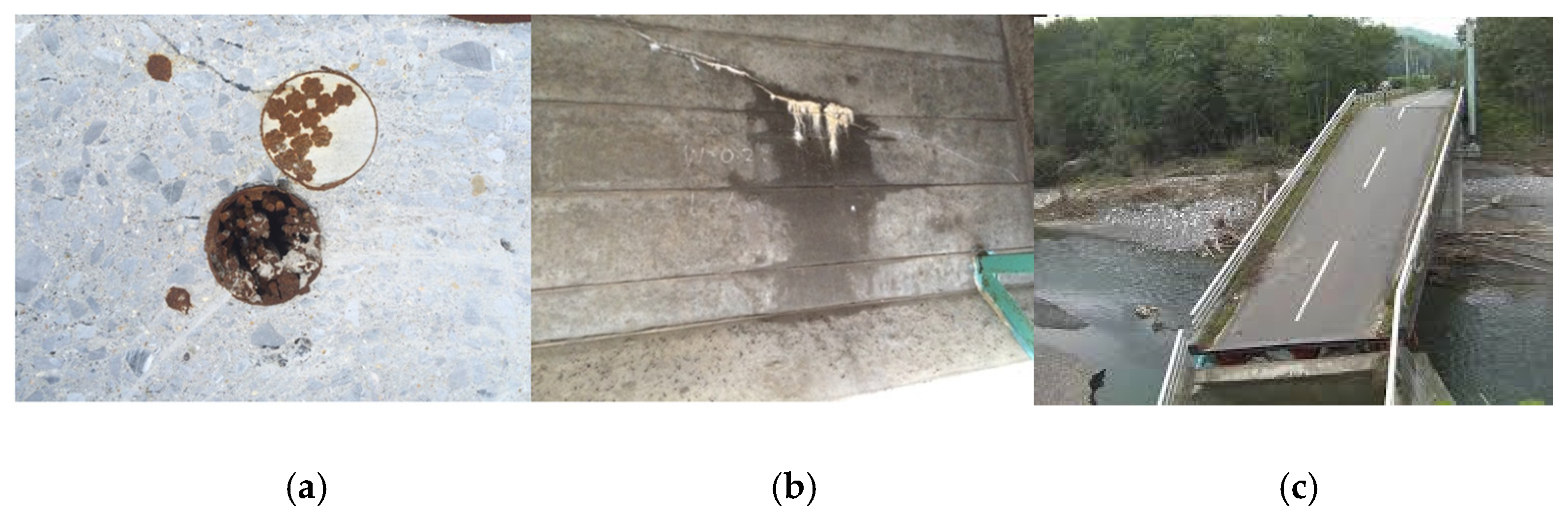
Figure 12a. The portable X-ray source box and magnetron box were lifted and finely positioned to the WEB part of the T-shaped PC girder bridge. The electric power source and water chiller are installed in a special vehicle with a 20 kVA electric diesel generator. The X-ray FPD was attached to the opposite side of the WEB part with respect to the X-ray source. Based on visual inspection, the WEB part indicated by the lines became the target ((b)). We found large surface concrete cracks and an exuded white Ca water stain. The inspection region of the PC wires, shown in (b), was examined using an X-ray source.
Figure 12c shows the surface cracks and the stain and X-ray transmitted images at the two flaws. In the two X-ray images, we observed declined PC sheaths, where PC wires and grout were inserted, and vertical/horizontal reinforcing rods. In the upper and lower cases, the lower halves beneath the PC wires appear dark/black and bright/white, respectively. In particular, it was speculated that the grout was unfilled and as a result, rainwater was retained in (c). Then, the PC sheath was corroded, and water exuded from the corroded cracks of the sheath to the surface via cracks in the concrete. The obtained X-ray images were attached to the design drawing, as shown in
Figure 12d. The inner situation of the PC sheaths in a rather wide region was then visualized.
We then evaluated the stage of unfilled grout in the PC sheath by gray value plotting, using the ratio of the gray values of unfilled grout and PC wires from the measured X-ray images. Here, we needed to consider and calibrate the uniformity of the background X-ray intensity distribution.
The X-rays used were emitted from a point with diameter of 2 mm at the W target and collimated by 17° by the W collimator. Therefore, the X-ray intensity at the FPD had an axisymmetric distribution. As the radius increased, the intensity decreased. As shown in
Figure 13, if the source releases the X-ray beam in parallel, the dose is equally received by the detector at every location. The beam distribution is uniform. However, the X-rays from our point-source have a cone shape and radial intensity distribution at the FPD, as shown on the right-hand side of the figure.
A typical X-ray image is shown in
Figure 14. This was acquired from a 200 mm-thick WEB part of the T-shaped PC girder bridge using the 950 keV X-ray source. The PC sheath, wires, and other rods are observed. The definition of the gray value is shown in
Figure 15. In this measurement, the black and white parts correspond to highly and slightly X-ray-attenuated parts, respectively. According to the X-ray attenuation coefficient, PC wires appear very dark while grout in the PC sheath and concrete appears bright. The locations of typical materials such as PC wires, rods, concrete, and filled/unfilled grouts are shown in
Figure 14.
Then, we checked the background X-ray intensity distribution on the line segment, as indicated in
Figure 14. Here, we used an 8-bit system so that the full scale corresponds to 256. Darkness, or a lower gray value near the corners, is a result of an ununiformly distributed X-ray dose. The effect must be considered when the evaluation is based on gray values. The gray value of the line segment, where only concrete exists (see
Figure 14), is plotted in
Figure 16. An 8th-degree polynomial fitting curve was added to the original profile. At that stage, the relative background X-ray intensity distribution was obtained. These data were utilized to compensate for the gray values of unfilled grout and PC wires to obtain their ratio, which is the proposed index for the stage of unfilled grout.
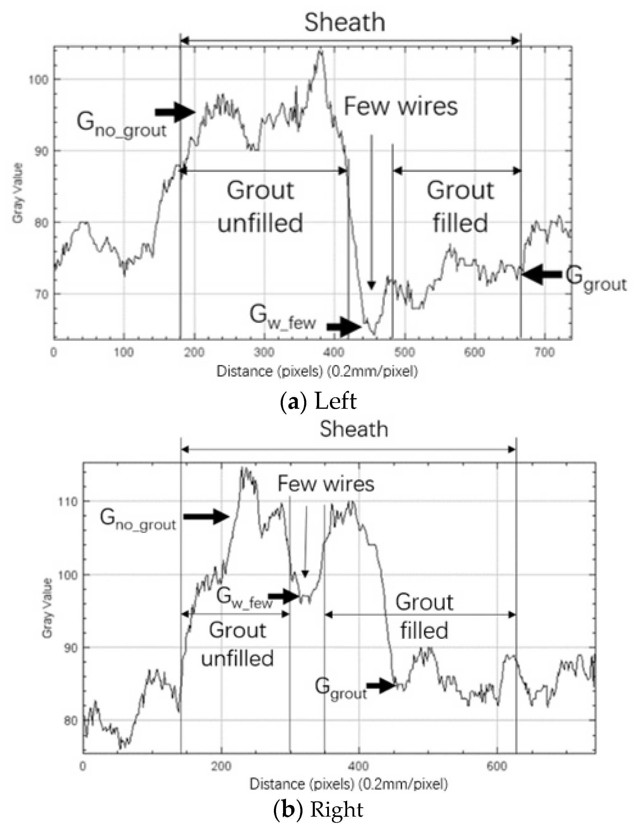
Schematic gray value profiles of the filled and unfilled grout cases are shown in
Figure 17a. In fact, these lie on the background of the X-ray point source, as shown in (b). In this measurement by the X-ray FPD, heavy and light materials appear dark and gray, respectively. The gray values of the dark and gray parts correspond to the low and high gray values, respectively. We needed to evaluate the background X-ray intensity distribution first and subtract it from the measured data. We tried to represent the gray value at the plateau,
Gw, for PC wires, as shown in (a). The boundary to the grout area appeared to be less dark and its gray value,
Gw_few, became lower because only a few wires were located. There was gradation in the region of the filled grout as the effective thickness changes (see (a)). Thus, the medium gray value was selected for the filled grout as
Ggrout. The gray value at the high/bright peak was regarded as
Gno_grout. The ratio,
K, of the gray values at filled/unfilled grout and PC wires was calculated for several situations as
Because Gw is lower than Ggrout and Gno_grout, both Kuw and Kfw must be higher than 1. Kuw at the unfilled grout must also be higher than Kfw at the filled grout, as explained above.
The inner contents of the image in
Figure 14 are explained in
Figure 18. The grout appears wholly unfilled in the broken line frame. The bright blank indicates the vacancy at this location, leading to a high dose at the FPD, which reveals a grout flaw. In comparison, the dark straight region above the broken line frame indicates the existence of PC wires, which remarkably attenuate X-rays. To make a quantitative evaluation, it was necessary to establish a method based on sufficient numerical tools. Gray value evaluation of the raw images was expected to be effective on this occasion.
Figure 19 shows the gray value profile plotted along the line segment that crosses the PC sheath transversely. The diameter and thickness of the PC sheath tube were ~38 mm and ~1 mm, respectively. Approximately 15 PC wires of ~7 mm in diameter were installed in a sheath. Each wire can be recognized almost entirely. The magnified profile of the gray value across the PC sheath is shown in
Figure 19. We can clearly observe the locations of the PC wires and grout in the concrete. The dark and bright/white parts of the PC wires and grout correspond to the lower and upper gray value peaks, respectively. This quantitative result is consistent with our visual recognition of the original X-ray image. That is, the bright/white part beneath the PC wires appears as a fully unfilled grout. This is supported by gray value analysis. Thus, this case can be evaluated as a fully unfilled grout.
Next, we proposed a quantitative index of the stage of the unfilled grout. The gray value profile along the line segment across the PC sheath and nearby reinforcing rods (see
Figure 20) was obtained, as shown in
Figure 21. Regions of “A” and “B” correspond to the PC wires and unfilled grout, respectively. A few wires are seen less to be dark in the region between them, as depicted in
Figure 17a. Additionally, two lower peaks attributed to the two rods can be clearly observed as “C” and “D”. Because this profile contains an ununiform background distribution of irradiating X-rays, it has to be compensated by using the data shown in
Figure 16. The compensated profile is shown in
Figure 22. We used these compensated profiles for the gray value analysis to evaluate the filled and unfilled grouts quantitatively.
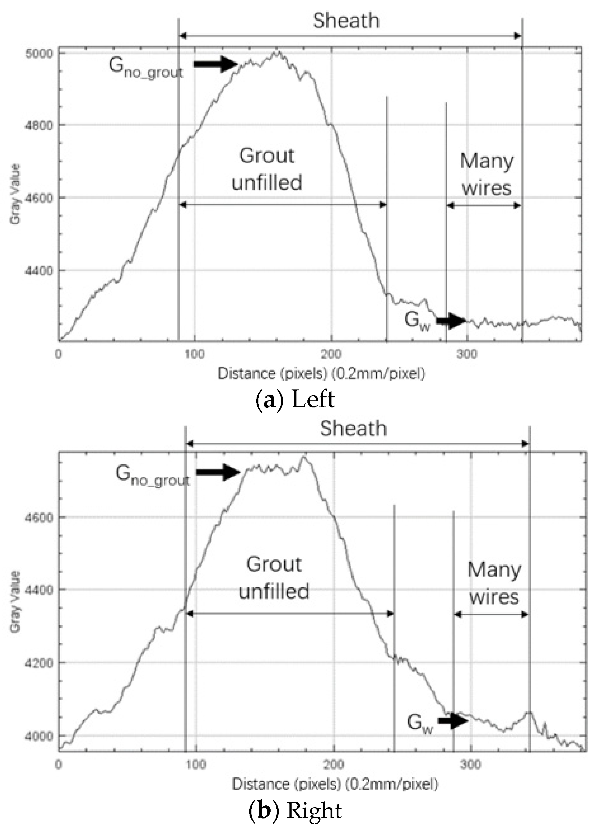
Line segments for gray value analysis are indicated in
Figure 23 in this X-ray image of the 200 mm thick WEB of the T-shaped PC girder bridge by the 950 keV X-ray source. The gray-value profiles are shown in
Figure 24.
By identifying the sheath range within the gray value profile, gray values could be obtained. The evaluated values are summarized in
Table 2. As predicted above, the average ratio of
K is clearly higher than 1 and is approximately 1.4.
Moreover, we plotted another set of gray values for the unfilled grout.
Figure 25 shows the original image of the same WEB part (200 mm-thick T-shaped PC girder bridge) taken by the 950 keV source. The inspection location is different from that shown in
Figure 23, as exhibited in
Figure 12d. Line segments for gray value analysis are also indicated in the figure.
The gray value distributions on the line segments in
Figure 25 are shown in
Figure 26.
Table 3 lists the gray values and
K ratios. The average ratio of
Kuw is approximately 1.5. Meanwhile,
Kuw_few is lower at ~1.1 This is because the parts of many and a few wires look dark and less dark, that is,
Gw_few >
Gw.
After looking into the unfilled sample, we proceeded to the filled grout case.
Figure 27 shows an image taken from the same WEB part (200 mm-thick T-shaped PC girder bridge) by the 950 keV source. The lower half of the PC sheath appears to be dark compared to that in
Figure 23 and
Figure 25. Line segments for plotting the gray values are also observed.
In the same way, the profiles were plotted as shown in
Figure 28, and the
K ratios are calculated in
Table 4. The average ratio of
Kfw is ~1.3, which is lower than the
Knw of ~1.4 and ~1.5 indicated in
Table 2 and
Table 3. If we used the gray value at the wire boundary,
Gw_few, the ratio of
Kfw_few became rather low at ~1.1. Again, the gray value at the wire boundary does not appear appropriate for the evaluation of unfilled and filled grouts.
4.2. Model Samples of 750 mm Thickness for Box-Shape PC Girder Bridge
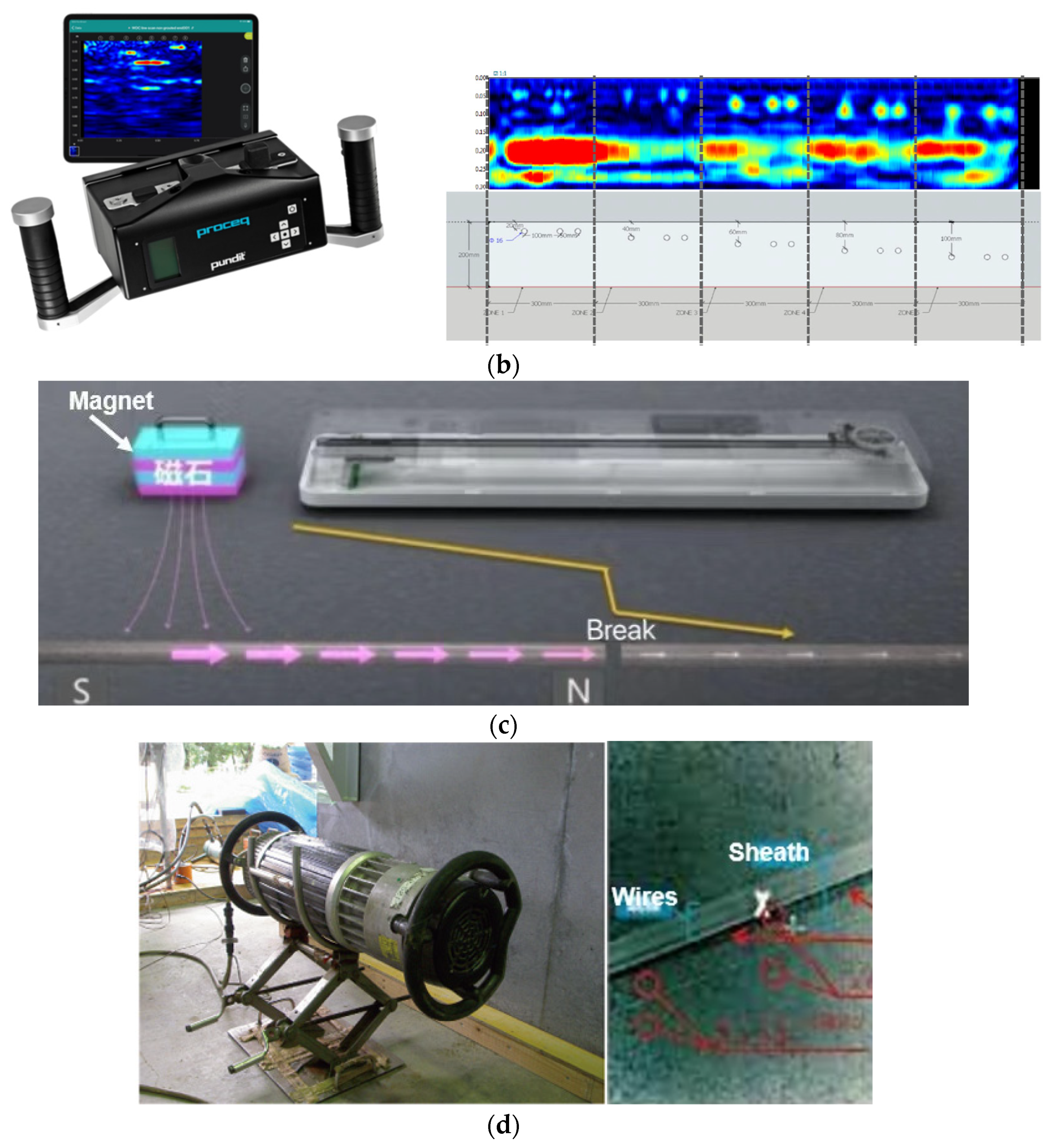
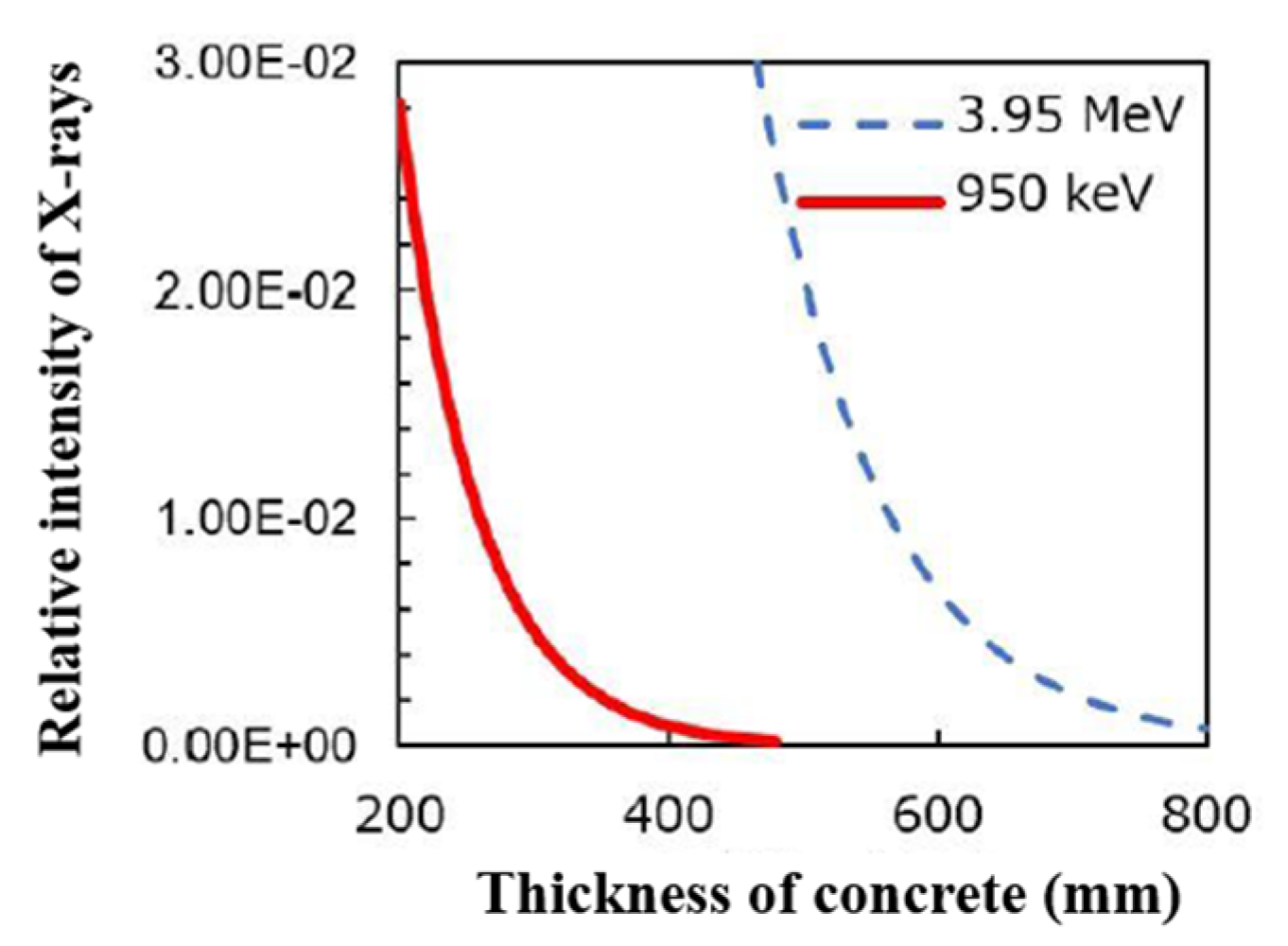
Now, we explain the similar filled/unfilled grout analysis for the side WEB of a box-shaped PC girder bridge using the 3.95 MeV X-ray source. Because the PC concrete thickness is far greater than 400 mm, we needed to use the 3.95 MeV X-ray source here. Real bridge inspection continued, and the obtained results are currently under evaluation. Hence, the results of the preparatory experiments modeling the real situation are introduced in this paper.
The target was a 750 mm thick PC WEB wall. We constructed model samples using pieces cut from real old bridges. The 750 mm thick assemblies are located between the 3.95 MeV X-ray source and the X-ray FPD detector, as shown in
Figure 29a. The photograph is shown in (b). The PC wire used for insertion is shown in (c).
For better image quality, multiple X-ray shots should be averaged into a single image. As shown in
Figure 29, the 750 mm-thick assembly is irradiated by the 3.95 MeV X-ray source.
Figure 30 shows the X-ray images for 1, 25, 50, and 100 shots, where one shot means 10 s exposure, and their averages are taken for each image to smooth the image [
19]. When the exposure time is short and the transmitted X-ray intensity is weak, the image appears spotty and the gray value profile becomes noisy. If the exposure time is increased, the profile is expected to be smoother. Such a denoising effect by stacking 1, 25, 50, and 100 X-ray shots is clear, as shown in
Figure 31. The noise attributed to the lack of X-ray intensity is remarkably reduced for many stacking shots. Because the concrete is significantly thick, the intensity of the transmitted X-ray becomes attenuated. Therefore, stacking using appropriate shots is necessary for an accurate quantitative analysis of filled and unfilled grouts based on their gray value difference.
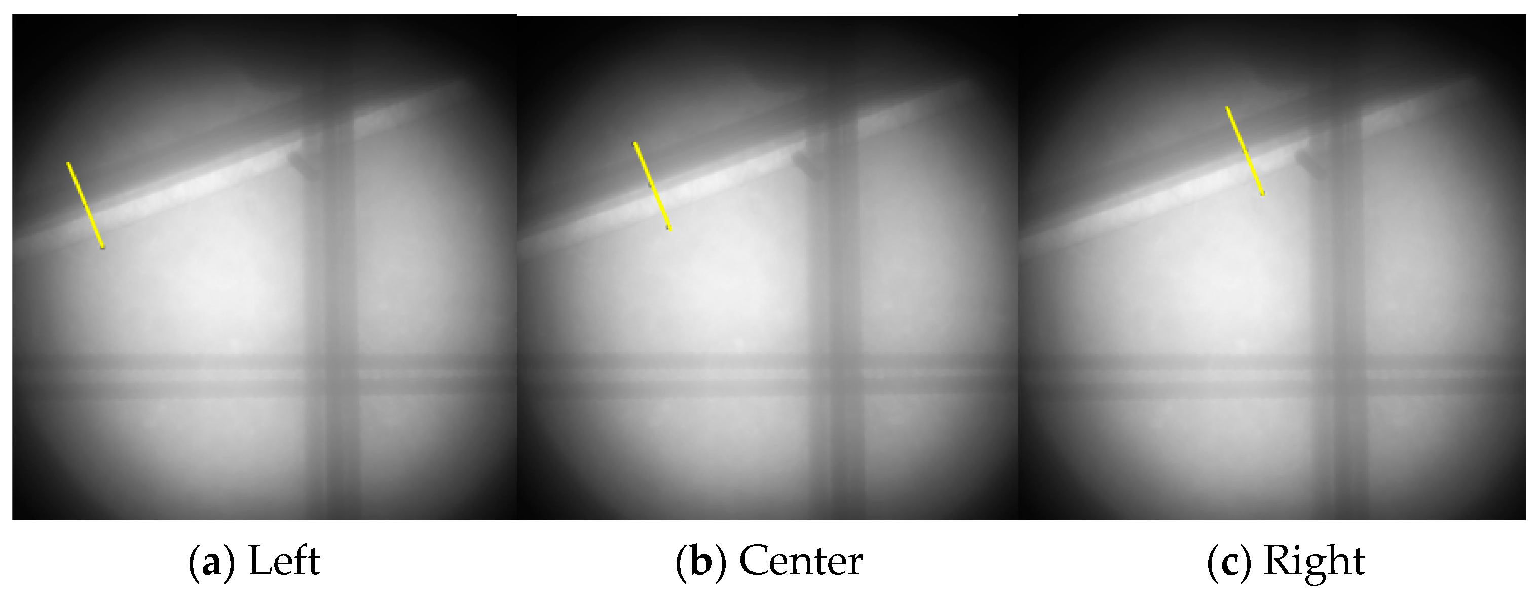
Now, X-ray images taken by the 3.95 MeV source for the model samples of a box-shaped PC girder bridge were analyzed. The inner contents of the samples are shown in
Figure 32. Two declined sheaths can be observed. In this case, only a few wires are inserted into the remaining grout in the upper sheath 1, and many wires are located in the lower sheath 2. The gray value profiles were evaluated on the indicated line segments. Gray value profiles and analysis were performed, as shown in
Figure 33. A few wires are clearly recognized by the small negative peak in the figure. The calculated values are listed in
Table 5. Because there were only a few wires in sheath 2, only
Kuw_few and
Kfw_few were evaluated. Additionally,
Kuwf was calculated.
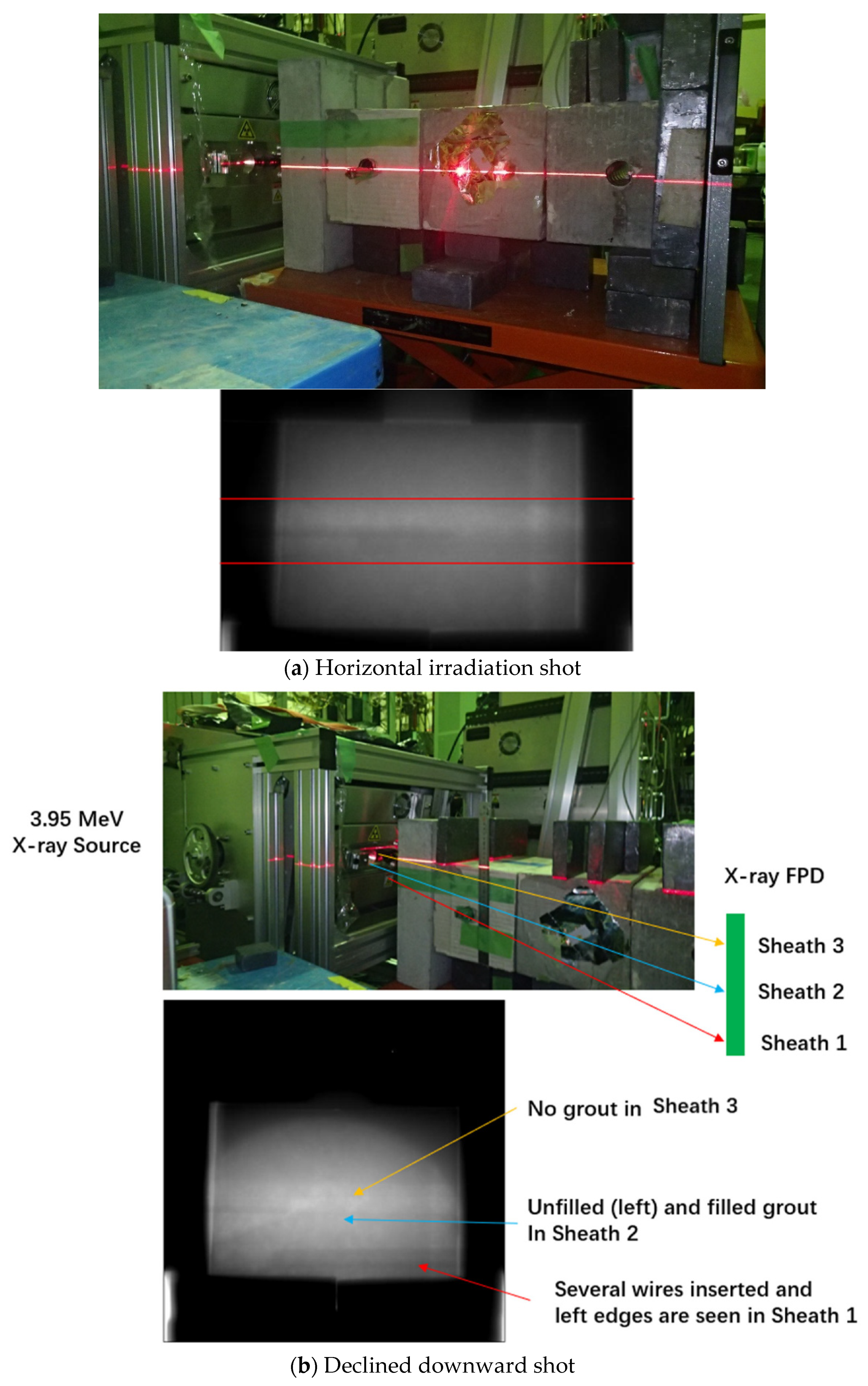
We then analyzed an additional case for the 750 mm thick concrete of a box-shaped PC girder bridge. We prepared three sheaths, 1, 2, and 3, at the same horizontal level, as shown in
Figure 34. In the lower half of sheath 1, several wires were inserted, whereas the upper half was vacant. The grout is filled only in the lower half of sheath 2, and a few wires are placed on it. Sheath 3 is completely empty. First, we carried out a horizontal shot in (a). In this case, only sheath 1, which is the nearest to the X-ray source, could be clearly recognized. We could also observe a few wires in sheath 2 at the wire grout boundary in the X-ray image. Next, the downward shot was reduced to shift the images vertically at the FPD, as shown in (b). The three sheaths were still partially overlapped at their edges.
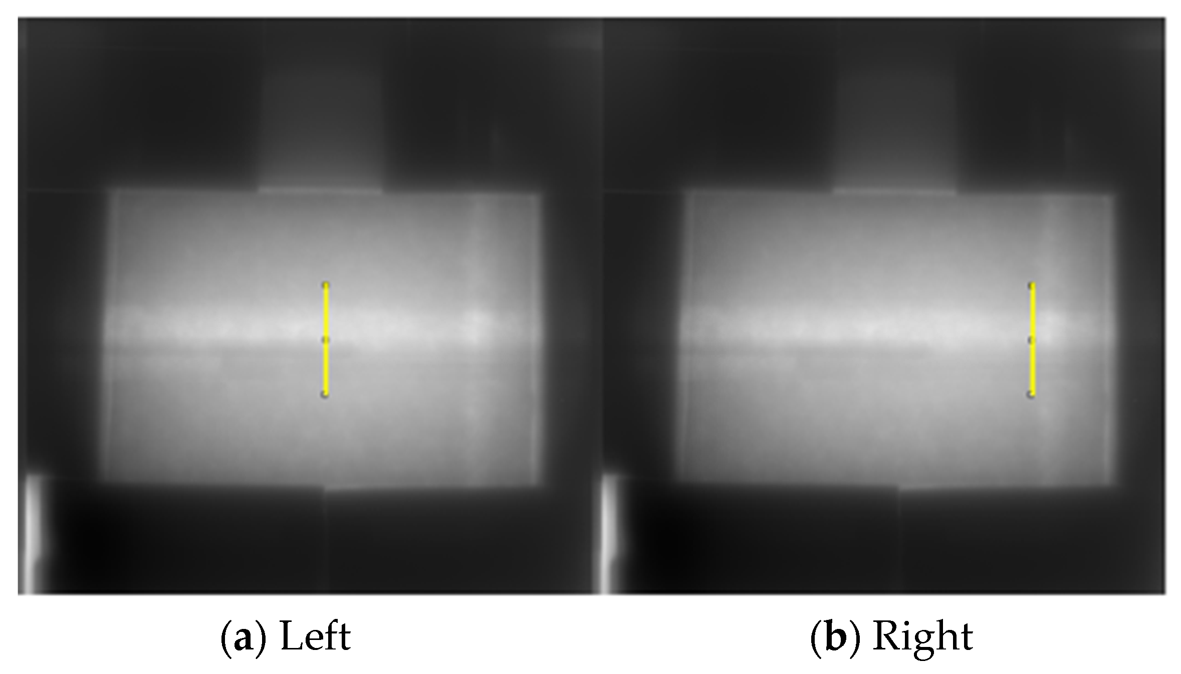
Because the three sheaths partially overlap at each edge, treatment of the regions and gray values was complicated for the gray value analysis in the declined shot case. Thus far, the inner structures were also rather complicated. Therefore, we also adopted a 16-bit system with a full scale of 65,536 to upgrade the resolution of the analysis. Thus, the gray value profile analysis was performed only for sheath 1 in the horizontal shot case, as shown in
Figure 35 and
Figure 36. We could also observe a few wires in sheath 2 near the wire grout boundary of the sheath 1 image in
Figure 35. Therefore, we did not use the gray value at the boundary as
Gw_few and only calculated
Knw.
Knw became ~1.2 as given in
Table 6.


 ,
, 


