Article

Quality Evaluation of Epoxy Pore Casts Using Silicon Micromodels: Application to Confocal Imaging of Carbonate Samples

The Ali I. Al-Naimi Petroleum Engineering Research Center, King Abdullah University of Science and Technology, Thuwal 23955-6900, Saudi Arabia
*
Author to whom correspondence should be addressed.
Appl. Sci. 2021, 11(12), 5557; https://doi.org/10.3390/app11125557
Submission received: 13 May 2021 / Revised: 4 June 2021 / Accepted: 8 June 2021 / Published: 16 June 2021

Abstract

:
Pore casting refers to filling the void spaces of porous materials with an extraneous fluid, usually epoxy resin, to obtain a high-strength composite material, stabilize a fragile porous structure, produce a three-dimensional replica of the pore space, or provide imaging contrast. Epoxy pore casting may be accompanied by additional procedures, such as etching, in which the material matrix is dissolved, leaving a clean cast. Moreover, an epoxy resin may be mixed with fluorophore substances to allow fluorescence imaging. Our work aims to investigate and optimize the epoxy pore casting procedure parameters, for example, impregnation pressure. We use silicon micromodels as a reference to validate the key parameters of high-pressure resin impregnation. We demonstrate possible artifacts and defects that might develop during impregnation with resin, e.g., resin shrinkage and gas trapping. In the end, we developed an optimized protocol to produce high-quality resin pore casts for high-resolution 3D imaging and the description of microporosity in micritic carbonates. In our applications, the high-quality pore casts were acid-etched to remove the non-transparent carbonate material, making the pore casts suitable for imaging with Confocal Laser Scanning Microscopy (CLSM). In addition, we evaluate the quality of our etching procedure using micro-computed tomography (micro-CT) scans of the pre- and post-etched samples and demonstrate that the etched epoxy pore casts represent the pore space of microporous carbonate rock samples with high fidelity.

1. Introduction

The saturation of porous samples with extraneous material, e.g., epoxy, that provides a contrast between the optical and/or electric properties of the void space and material grains has been used extensively in various fields. Paleontologists Waters and Savage [1] pioneered the use of epoxy pore casts in the characterization of microfossils by optical microscopy, while Purnell [2], Mihlbachler et al. [3] used Scanning Electron Microscopy (SEM) and Confocal Laser Scanning Microscopy (CLSM).
In bioscience, pore casts are widely combined with CLSM in tissue characterization and dental morphology [4]. On the other hand, archaeologists use surface casts as an analytical tool to understand material cultures through experimentation to imitate ancient gestures and technologies [5]. In geoscience, pore identification from pore cast thin-section images is widely used to estimate porosity and evaluate the types of pores and pore structure parameters [6,7,8,9,10,11].
For geological samples, epoxy resin casting is typically used to preserve the mechanical integrity of the sample and produce 15-micrometer thick rock slices. Blue dyes enable porosity counting, and fluorescent dyes have been receiving increasing attention recently in geoscience for fluorescent or confocal imaging. Several studies have reported applications of epoxy pore casts to gain a better understanding of the fluid flow capacity of carbonate rocks [12,13,14]. In this work, using a well-known pore geometry, we experimentally determine the optimal resin impregnation parameters for high-resolution 3D imaging.

1.1. Resin Impregnation

Despite the importance of rock saturation with epoxy resin, currently, there exists no standard approach for high-pressure pore casting. The impregnation procedure generally consists of three steps: (i) resin preparation, (ii) rock sample degassing, and (iii) resin injection into the sample. Vacuum impregnation or vacuum pore casting is the most widely adopted method of resin pore casting. It is used to produce thin sections of geological samples [15], cement [16] or reinforced wood. Alternative methods, such as high-pressure impregnation and epoxy-solvent replacement, are also adopted for rock analysis [8,17]. The preference for the vacuum process stems from its low cost, safety, and general availability of laboratory equipment.
Although vacuum impregnation is a simple and efficient method for preparing standard rock thin sections, it has some limitations when the samples are tight or microporous. A key limitation of vacuum impregnation is that the epoxy resin cannot access the pore volume associated with sub-micron scale pore throats, a major issue in microporous and tight rock samples. In addition, the application of a vacuum for a long time for a complete pore filling of a rock sample may deform the pore shapes [18] or even induce cracks [19].
Beckett and Sellwood [20] specified certain experimental parameters for impregnating carbonate samples at high pressure generated by nitrogen gas. However, their description did not address any artifacts or defects that may emerge during the impregnation process. For example, the impact of dissolved gas in the epoxy mixture was not considered a source of defects. The vacuum level at which the degassing step occurs prior to applying high pressure has varied significantly in the literature—even for the same material.
Porous materials were reported to be impregnated at different vacuum levels. For example, unconsolidated samples were impregnated at 700–800 mbar [21,22], while higher vacuum levels (8–30 mbar) were used for cementitious materials [19,23]. Rock samples on the other hand are impregnated under more aggressive vacuum levels to ensure that the air is evacuated from the sub-micron scale pore throats. Carbonates and tight rocks were reported to be degassed under 1.33 mbar [20] and 0.067 mbar [24], respectively.
Some studies, e.g., [15,25,26,27], suggested that mixing solvents, such as acetone or toluene, into epoxy material to decrease its viscosity for more efficient impregnation. Such a technique negatively impacts the shrinkage of the epoxy. However, shrinkage has been considered irrelevant or “negligible” in earlier studies [15,20,24,25,28,29]. While it may hold true for linear shrinkage determined according to the standard ASTM and low solvent fractions, we will show below that other types of shrinkage defects may develop using this technique. Unless prevented from occurring or properly identified in the samples, these defects may lead to false interpretations of the subsequent high-resolution images.
All these variations and discrepancies regarding the resin impregnation procedure have resulted in the general lack of standard sample preparation protocol. In this study, we used custom-fabricated micromodels with well-defined pore geometry to validate the parameters of high-pressure resin impregnation. Based on these experiments, we attempted to address the above-mentioned concerns and provide guidelines for obtaining high-quality pore casts for high-resolution imaging. We applied the optimized resin-impregnation-procedure and produced quality epoxy pore casts for high-resolution 3D imaging with CLSM.

1.2. Confocal Imaging

CLSM is an imaging technique that can increase the optical resolution and contrast of a micrograph by eliminating out-of-focus light. CLSM uses a laser light source tightly focused through a slit or pin-hole aperture, limiting the depth of field to a single plane. By varying the focal point, the confocal microscope can obtain multiple images of different surface planes to produce a sharply focused 3D image of the object [30].
During CLSM imaging, the true 3D resolution is, thus, accomplished by actively suppressing light waves coming from out-of-focus planes [31]. CLSM can achieve resolutions of around 0.2 and 0.3 µm in the XY and Z planes, respectively, by using high numerical aperture (NA) objectives and by minimizing the pinhole size [32]. However, the imaging depth of CLSM is small for non-transparent materials because light scattering limits laser penetration and degrades the obtained fluorescence signal. CLSM penetrates as deeply as 7 µm for concrete [26], 90–100 µm for sandstone [33,34], and 10 µm for carbonates [27,35].
In this study, we image silicon micromodels impregnated under different conditions and identify defects and artifacts that may emerge during gas-assisted high-pressure resin impregnation. Based on these experiments, we optimized the parameters of the process for high-resolution 3D confocal imaging of pore space. Implementing the optimized approach, we were able to obtain high-resolution 3D images of the microporosity present in carbonate samples.

1.3. X-ray Computed Tomography (XCT)

X-ray Computed Tomography (XCT) illuminates a specimen with X-ray photons, which interact principally with electrons in the target. Thus contrast in XCT images is generated by local differences in mass density and mean atomic number. In a typical cone beam system, such as the one used in this study, the rotating sample is exposed to an X-ray beam from a point source and the transmitted X-rays are captured by a detector. The 2D radiographs produced during the image acquisition are then ‘reconstructed’ into 3D tomography images using specially designed reconstruction algorithms.
More details of the working principle of XCT imaging and recent advances can be found in [36,37] and the references therein. Although both CLSM and XCT can be used to obtain 3D images of a suitable sample, they are different in terms of the acquisition methods, image processing, volume of investigation in 3D, and image resolution. An important difference is that the samples need to be optically transparent for confocal imaging, whereas XCT imaging can be used for optically opaque samples.
The fields of application of CLSM and XCT imaging, therefore, vary significantly, in that the former is most widely used in biosciences, whereas the latter is also prominently used in physical and materials science applications. XCT is frequently used for the non-destructive characterization of materials, for example metal composites and alloys [38,39]. In this study, we used micro-CT, a high resolution industrial XCT, for evaluating the quality of the resin pore casts.

2. Methods

2.1. Silicon Micromodels

2.1.1. Lithography

Single-side polished, P-type, <1,0,0>, four-inch silicon wafers with a thickness of 525 µm, procured from LUVA System Inc. (Santa Clara, CA, USA), were used in this study. First, the silicon wafers were spin-coated with a positive photoresist, AZ 5214, procured from Merck Performance Materials GmbH, at the speed of 2800 r/min for 40 s, to make the photoresist reach a thickness of around 1.6 µm. Second, the coated wafers were prebaked on hot plates at the temperature of 110 C for 2 min. Third, the Heidelberg μ PG 501 was used to direct-write custom patterns, shown in Figure 1A, on the silicon wafers using a laser with 390 nm wave-length and exposure time of 55 ms. Finally, the wafers were developed in AZ 726 MIF, procured from Microchemicals GmbH, for 1 min.

2.1.2. Deep Reactive Ion Etching (DRIE)

Etching the patterns into the silicon models was carried out using DRIE following the Bosch procedure [40], in which the etching and passivation steps are used alternatively to etch the silicon wafers vertically. We used the Plasmalab System 100 provided by Oxford Instruments. The passivation and etching parameters are summarized in Table 1.
After running the etching and passivation steps alternatively 180 times for about 45 min, approximately 100 µm of the engraved pattern was etched in the silicon wafer. Afterward, another run was required to etch the inlets through the entire wafer thickness. Finally, the silicon micromodel was sealed from one end with a glass wafer using anodic bonding.

2.2. Sintered Glass Beads

Class V soda-lime glass spheres of 75–90 µm in size were procured from Mo-Sci specialty products, L.L.C. The beads were packed inside a 1-m square quartz capillary that was sealed from one end. The capillary was then loaded into an oven preheated to 870 C . The capillary was kept inside the oven for only 3 min, giving enough time for the beads to be sintered. Longer heating periods caused melting. Figure 1B shows the final sintered glass bead model.

2.3. Materials

2.3.1. Resin and Chemicals

For impregnation, we used a two-component amine-cured epoxy resin R3501/H5064 (part A polymer and part B hardener) with a mixture viscosity of 468 cP and a glass transition temperature of 54– 57 C procured from EpicResins Inc. (Palmyra, WI, USA). The fluorochrome used to dye the epoxy was Rhodamine-B, procured from Alfa Aesar (Ward Hill, MA, USA). This particular epoxy resin and dye were selected after testing several combinations of commercially available products.
The fluorescence excitation and emission wavelengths of Rhodamine-B are in the range of 514–568 nm and 570–600 nm, respectively. Rhodamine-B was dissolved in part A of the epoxy with a weight ratio of 1:200 by stirring with magnetic stirrer for an hour until complete dissolution. Then part B was added to the solution, usually with 25% excess to what was recommended by the supplier, to avoid developing shrinkage defects due to the low conversion ratio caused by the evaporation during application of the vacuum when the resin vitrifies as discussed earlier.

2.3.2. Viscosity Measurement

Epoxy resins have a low initial viscosity that grows with time exponentially. While curing, the resin undergoes chemical reactions that cross-link the polymer chains and, thus, connect the entire matrix together in a three-dimensional network until it solidifies. The authors in Canamero-Martínez et al. [41] expressed the evolution of viscosity μ with the following equation:
μ ( t ) = μ 0 e k n t
where μ 0 is the initial viscosity before the start of curing, k n is a rheological kinetic constant measured experimentally, and t is the time. In Figure 2, we plotted the viscosity measurements of the pure resin and compared them to the resin diluted with toluene at three different weight ratios, 5%, 10%, and 30%. The viscosity was measured for 3 h using an electromagnetic viscometer, EMS 1000, provided by KEM Kyoto Co., Ltd. (Kyoto, Japan) Then, the constants μ 0 and k n in Equation (1) were determined for every mixture so that the viscosity behavior could be extrapolated.

2.3.3. Rock Samples

We used the well-known Indiana limestone for rock impregnation which has the porosity of 0.17, and permeability of 180 mD. We machined 5 mm cubic samples from 1.5-inch core plugs to be more suitable for epoxy impregnation. Indiana limestone is of the Mississippian age and is quarried from the Salem Formation, Indiana [42]. Indiana limestone can be classified as a fossiliferous, calcite-cemented grainstone predominantly composed of pellets, moderately rounded skeletal grains, ooids, and shell fragments.
The allochems were coated with micritic cement, which comprises equant sparry calcite crystals. The well-connected intergranular pores commonly dominate the pore system in the Indiana limestone rock type used in this study [43,44], which makes up the pore space between the allochems. The micritic material of the pore-lining micritic cement was highly microporous (MC). Micropores were also observed within the microcrystalline material of the allochems resulting in intragranular microporosity (IGM).

2.3.4. Pore Throat Size Measurement

We used Mercury Intrusion Porosimetry (MIP) to evaluate the pore size distribution of the carbonate samples used in this study. The MIP results, plotted in Figure 3, indicate the bi-modal pore types with a median and minimum pore throat diameter of 39.1 µm and 0.04 µm, respectively. This bimodality is due to the contribution of MC created by fine calcite crystals lining the pores and the IGM present in the allochems, mainly oolites.

2.4. Vacuum Impregnation and Degassing

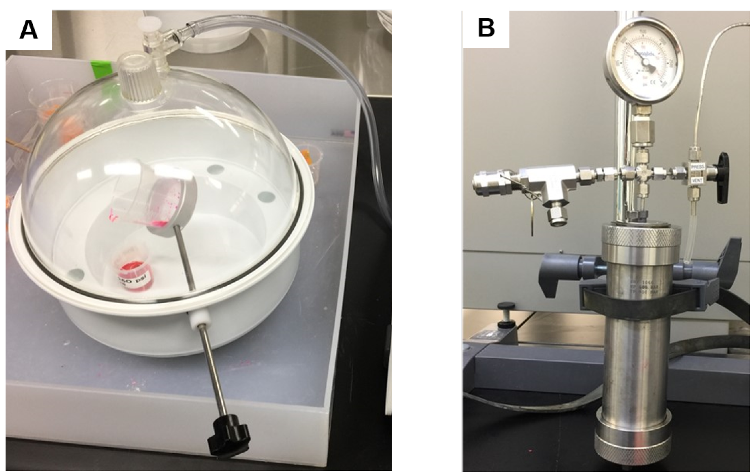
A desiccator with a tilting handle, shown in Figure 4A, was connected to a pump for pulling vacuum and degassing the epoxy and the impregnated material. The vacuum impregnation unit model was LSSA-011, procured from Pace Technologies. For the vacuum levels of 10 mbar and higher, we used a vacuum oil pump model 15501 procured from Robinair, and for the vacuum levels of 120 mbar and higher, we used an in-house vacuum. The sample and epoxy mixtures were vacuumed together in one chamber without being in direct contact. For the vacuum levels of 120 mbar and higher, the degassing procedure typically lasted for 15 min. For the vacuum levels below 10 mbar, the duration was approximately 5 min. Otherwise, the epoxy would boil quite aggressively. Then, the epoxy was poured over the sample contained inside a disposable mold.

2.5. High-Pressure Impregnation

Once the degassing procedure was completed, the samples were immediately transferred into the high-pressure vessel shown in Figure 4B and slowly pressurized at a rate of 50 psi/min to 1000 psi (6.5 MPa) with G6 nitrogen. The desired pressure was reached via a high delivery pressure regulator (Air Liquide, model Q1-208CS-CGA580). The high-pressure vessel was a pipe cell procured from MetaRock Laboratories with a 60-mm diameter and 190-mm height, made of 17-4 PH annealed stainless steel, and tested up to 13,000 psi (89.7 MPa). The sample was kept under high pressure until the resin was completely cured; otherwise, excessive bubbles would emerge, as also discussed in Figure 10.

2.6. Sample Preparation

After the resin had been cured, the vacuum- or high-pressure impregnated samples were released from the disposable molds. The excess resin surrounding the sample was removed using M-Prep 5TM Grinder/Polisher from Allied High Tech. First, the sample was ground by silicon carbide abrasive paper (320 grit size) for 1 min, followed by 3 min and 5 min with the grit sizes 600 and 1200, respectively. The final polishing was done with a polishing cloth (Red final C) and a 0.04 µm colloidal silica suspension. Once polished, the samples were visually inspected using the Olympus BX61 optical material microscope for defects, such as bubbles and micro-fractures as well as polishing quality.

Etching

For high-resolution confocal imaging, we dissolved the rock matrix of the epoxy pore casts. We used 0.5 M HCl at room temperature to etch the Indiana limestone samples. Rather than etching the whole thickness of 5 mm, we etched the 1-mm slices of the impregnated sample, cut with a circular diamond saw. After 2 h, the acid was gently discarded from the samples and replaced with DI water. To remove traces of HCl, the water was exchanged several times over the course of 3 h. After rinsing with water, the sample was dried in air at room temperature. We observed that samples with a smaller thickness, smaller than 0.7 mm, may experience buckling after drying; therefore, it is recommended to ensure the sample thickness is not below 1 mm.

2.7. Imaging

2.7.1. CLSM Imaging

The impregnated samples were then imaged using the Zeiss LSM 880 confocal microscope. An argon 514 nm laser was used to excite Rhodamine-B. All impregnated micromodels were imaged by the 10× plan apochromat objective lens with a NA of 0.45. The epoxy pore casts of Indiana limestone were imaged using the aforementioned lens, and for higher magnification, the 20× plan apochromat water-immersion objective lens with a NA of 1. The photomultiplier gain was set between 450 and 580, while the laser intensity was kept between 2.5 and 3.5 for all the samples. The tile scanning module in Zen software enabled the imaging of samples across the entire investigation area. Stitching was implemented on the tiles with a 12–15% overlap.

2.7.2. Micro-CT

The impregnated epoxy pore cast of Indiana limestone was imaged using the uniTOM system provided by Tescan-XRE. The system was a closed-type X-ray tube with energy levels of 40–130 kV/39 W, and the acquired voxel size was 5.41 µm. We also performed time-lapse micro-CT scanning of the epoxy-impregnated samples, to evaluate any pore cast deterioration during etching, at incremental time intervals of 1 h during the first 10 h, and then after 12, 16, 19, and 69 h. The 2D radiographs of all the micro-CT scans performed in this study were reconstructed using the filtered back projection method. We used Avizo TM for pre-processing and visualizing the 3D tomography images. We used a non-local mean filter for denoising and the interactive overlay threshold method for segmentation of the rock and epoxy resin phases.

3. Results & Discussion

3.1. Assessment of Impregnation Parameters

We evaluated the impregnation parameters by understanding the mechanisms controlling resin impregnation in a porous medium. We qualitatively assessed the relative effect of each parameter and later used experiments to properly quantify them, as an explicit theoretical model was beyond the scope of our study. Hence, we assumed an incompressible Newtonian fluid in creeping laminar flow and neglected the time derivative of the fluid velocity and gravity. In this case, the Navier–Stokes equation reduces to
P = μ 2 v
where v is the fluid velocity, μ is the dynamic viscosity, and P is the pressure. Based on Equation (2), Caccia et al. [45] derived an expression to predict the infiltration distance ( h ) of polymers with variable viscosity into a porous composite material. In other words, the polymer/epoxy changed its viscosity while curing and loosing its fluidity as described in Equation (1). The derived relationship was
h 2 = 2 k Δ P ϕ μ 0 k n ( 1 e k n t )
where k is the permeability, Δ P is the differential pressure, and ϕ is the porosity. In the case of epoxy impregnation of a rock sample, the effective pressure was attributed to capillary forces and any external forces acting upon the surface of the epoxy. In Table 2, we show that epoxy wetted the silica surface. Similar behavior for carbonate impregnation has also been reported by others (e.g., [8,29,46]), thus, confirming the wetting behavior of epoxy on rock surfaces. Thereby, we can write
Δ P = 2 γ R cos θ + P i m p r e g
where γ is the surface tension and θ is the advancing contact angle. 2 γ R cos θ represents the capillary pressure and P i m p r e g is the impregnation pressure imposed on the resin. Now, we can rewrite Equation (3) to estimate the impregnation penetration length ( h ) as
h = 2 k ( 1 e k n t ) ϕ μ 0 k n ( 2 γ R cos θ + P i m p r e g )
Equation (5) was used to evaluate the impregnation of the epoxy system summarized in Table 2, into the Indiana limestone sample described earlier. Figure 5 plots the impregnation penetration length (h) against time for three different pressures: P i m p r e g = 0 bar models the behavior of epoxy in spontaneous inhibition, P i m p r e g = 1 bar models vacuum impregnation, and P i m p r e g = 65 bar models the high-pressure assisted impregnation. The relative effect of the imposed impregnation pressure on the impregnation penetration length is demonstrated. In this model, the flow stopped when the resin was too viscous to flow discernibly.
On top of the simplifications mentioned earlier, this model assumes single-phase flow and an absolute vacuum to be achieved, i.e., no possibility of modeling trapped gases, which is a major concern that we discuss in the following section. Several models have been proposed in the literature to address the limitations of this model [47,48,49,50,51,52]. Although the proposed model is a great simplification of the experimental system, it can provide useful insights into the impregnation process and its efficiency, which can be summarized as follows:
  • Resin should fill the pore space completely by spontaneous imbibition owing to its wetting behavior. However, this typically never happens in practice because of limited impregnation times.
  • The application of high pressure helps resin impregnation, especially at the significant pressures that can be generated in a laboratory. The drastic effect of pressure on the impregnation penetration distance is exemplified in Figure 5, where high-pressure-assisted impregnation is an order of magnitude longer than the other cases.

3.2. Factors Controlling Pore Cast Quality

To reveal the factors that determine the quality of resin impregnation, e.g., pressure, shrinkage, and trapped gases, we used the silicon micro models shown in Figure 1. In contrast to the complex heterogeneous pore space of rocks, our micromodels have clearly defined simple and straight pores, so even slight defects or artifacts from the resin impregnation procedure could be easily detected. Table 3 summarizes the main defect types.

3.2.1. Vacuum Level

To evaluate the efficiency of vacuum impregnation, we tested two scenarios: (i) residual pressure of 120 mbar, and (ii) residual pressure of 10 mbar. Figure 6 shows two micromodels impregnated according to the aforementioned scenarios. We observed two distinctive types of defects, Type 1 and Type 2, in both models. Green circles and ovals highlight Type 1 defects formed around trapped gas. These defects have round or elliptical shapes and appear mostly near the channel ends. The residual gas was snapped off and trapped in the channels. This interpretation is consistent with lower residual pressure experiments, where such defects were absent.
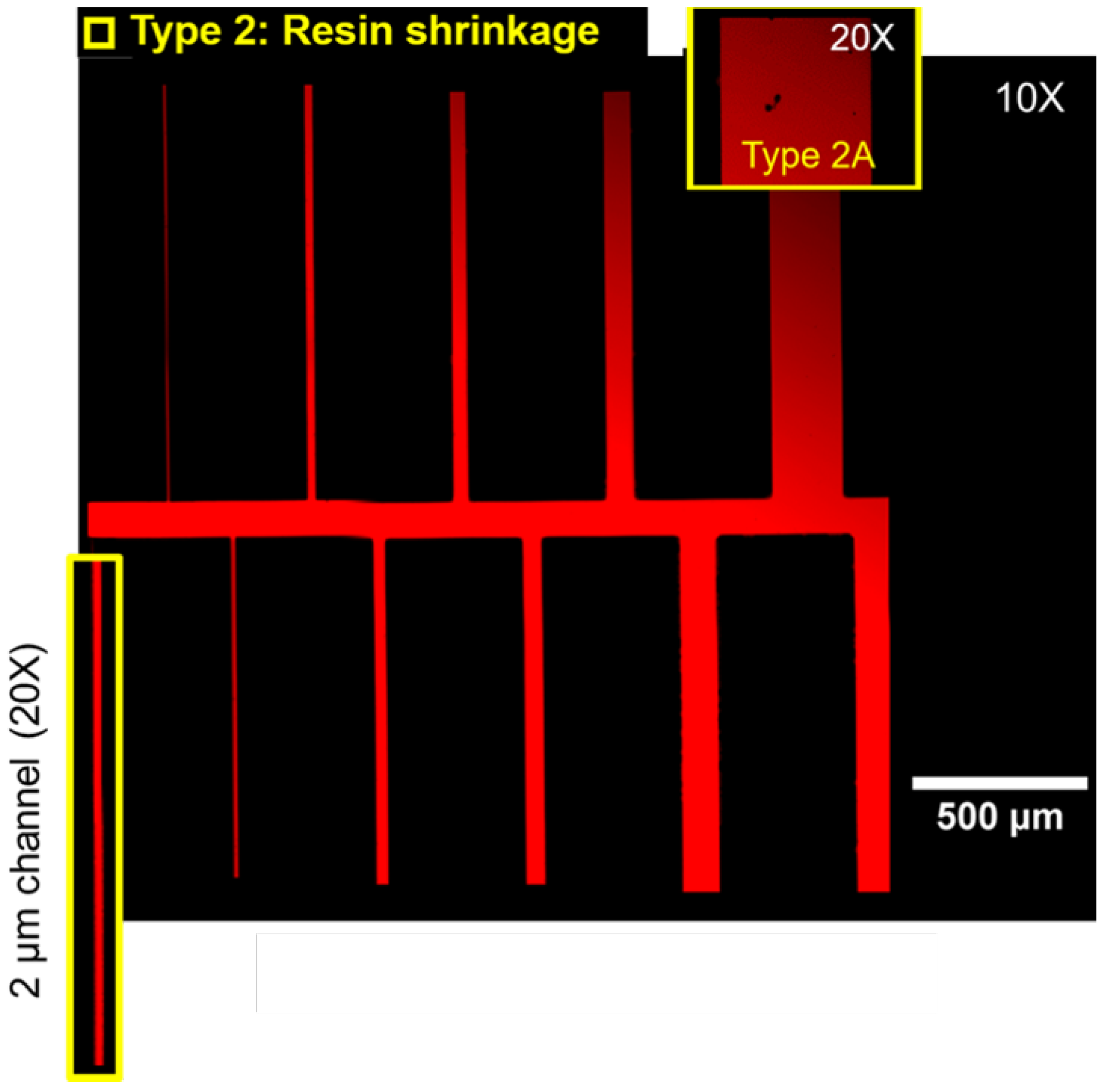
Type 2 defects are highlighted yellow in Figure 6. These defects are smaller than Type 1, have corrugated boundaries and irregular shapes. Resin shrinkage causes type 2 defects, which are frequently referred to as “volume decrease”. The two main causes of resin shrinkage are: (i) thermal expansion and contraction due to heating or cooling, and (ii) curing shrinkage due to polymer chain cross-linking after phase transition [53]. In this study, we were only concerned with the curing shrinkage since, in our experiments, the epoxy resin cross-linked at room temperature.
Figure 7 shows the two subtypes of shrinkage defects: (i) most frequent type 2A: voids of 10–40 µm in diameter, and (ii) rare type 2B: large cracks. Shrinkage defects are caused by tensile stresses that arise when the resin is cured inside a constrained volume to which it adheres [54,55]. Evidently, from our experiments, the large cracks seem to appear near stress concentration points mostly.
Shrinkage defects are more pronounced in Figure 6A, where the high vacuum level, 10 mbar, was applied. Reaching 10 mbar in our setup requiresed significantly more time than reaching 120 mbar. Long vacuum exposure results in excessive evaporation of the hardener despite the excess amount added. The hardener deficiency causes a lower resin conversion ratio, slows down gelation, and generates resin inhomogeneity and voids.

3.2.2. Impregnation Pressure

Figure 8 shows two silicon micromodels impregnated at low pressure (vacuum) (A) and at high pressure (B). We can clearly identify type 1 defects inside the impregnated model under vacuum (Figure 8A) and with less severity in the model that was impregnated under high pressure (Figure 8B). Hence, a degassing step before injection of the resin at high pressure is needed to reduce the defects by removing fluids from the sample and limit gas bubble formation.
As discussed earlier, the vacuum level control is crucial in limiting shrinkage defects formation where a higher vacuum level is associated with more abundant shrinkage defects; see Figure 6A. Therefore, we opted to use a lower vacuum level, 120 mbar, for the degassing step before high pressure-assisted impregnation. Figure 9 shows a micromodel impregnated at high pressure preceded by degassing at 120 mbar vacuum. The impregnated model does not feature type 1 defects even at the smallest channel, showing the importance of the degassing step. We still observed minor shrinkage defects, even though we used a low vacuum level. However, pressure-assisted impregnation preceded by degassing at a low vacuum level showed higher quality impregnation compared to other recipes, and hence it was applied to our rock sample impregnation.
Pressure-assisted impregnation may also play an important role in controlling the curing kinetics [53] and the mechanical properties of the cured epoxy resin [19]. Experimentally, this leads to increasing the curing time by almost 50%. Figure 10 shows an abrupt release of the dissolved gas when the sample was depressurized at the original curing time. On the other hand, resin curing under pressure prevents the volatile components from being released by applying a pressure greater than their vapor pressure.
This approach yields a denser structure free of porosity and with better mechanical properties [56,57]. Chen et al. [19], Gündüz et al. [58], Gündüz and Yalçin [59] all reported higher tensile and flexural strength samples in comparison with samples after the vacuum process, implying higher stability of the samples during the preparation phases, e.g., cutting, grinding, and polishing.

3.2.3. Viscosity Modifiers

Some authors suggested that adding solvents, such as toluene or acetone, lowers the viscosity of the epoxy mixture and results in better impregnation. We added toluene to the epoxy mixture at three different weight ratios: 5%, 10%, and 30%. We used the viscosity behavior of the different epoxy and toluene compositions, depicted in Figure 2, to estimate the resin impregnation penetration length according to Equation (5). Figure 11 shows h plotted against time for three epoxy mixtures under two different impregnation schemes.
The modeled behavior indicated no substantial change in the resin impregnation rate or volume unless the toluene weight ratio was more than 30%. However, the mechanical properties of the epoxy mixture with 30% of toluene deteriorated severely, i.e., lower hardness and toughness were observed. Figure 12 features two micromodels impregnated with different compositions of resin and toluene. We observed mechanical property deterioration and severe shrinkage defects, both type 2A and 2B, with a higher toluene/resin ratio.
Moreover, Figure 12A shows a clear phase boundary between toluene and resin mixtures despite the single-phase injected into the micromodel. The phase separation likely occurred during the epoxy resin curing, followed by the expulsion of excess toluene. Therefore, we conclude that adding solvents, such as toluene, impairs the quality of pore casts. This will not cause a significant increase in the impregnation volume but will cause severe defects that may lead to false interpretations.

3.2.4. Optimum Impregnation Parameters

When present in a pore cast, the various defects discussed above can lead to erroneous imaging results. Based on several experimental observations, we summarize the main attributes of the impregnation parameters as follows:
  • The vacuum level should not exceed 80 mbar for amine-based epoxy systems to avoid excessive shrinkage defects. Our guideline is different than the suggested values of 1.33 mbar [20] and 0.067 mbar [24] for carbonates and tight rocks, respectively.
  • Pressure-assisted impregnation is essential to ensure complete pore invasion. Pressures of up to 65 bars were experimentally verified to have no adverse effects on both sample integrity (i.e., no cracks) and resin curing.
  • A degassing step prior to pressurized-impregnation is needed to remove any fluid traces and avoid bubble formation.
  • The benefits of adding viscosity modifiers to the epoxy system do not outweigh the risks, and hence a selection of epoxies that have adequate viscosity (i.e., below 0.5 Pa · s) leads to a higher pore cast quality.
We followed these guidelines to fabricate high quality epoxy pore casts of microporous carbonate samples. Table 4 summarizes the impregnation parameters of Indiana limestone samples with the epoxy system described earlier.

3.3. Imaging Etched Carbonates Pore Casts

3.3.1. Pore Cast Quality

We used micro-CT imaging to evaluate the quality of the cured epoxy pore casts of the carbonate rock samples. Micro-CT images of the samples were screened for resin penetration depth and the aforementioned defects. We verified the homogeneity of resin impregnation throughout the full sample thickness of 5.1 mm. We did not find any changes in the intensity values through all 943 slices, one of which is shown in Figure 13. We can still identify some defects highlighted in Figure 13, but these defects represent only 0.21% of the total pore volume throughout the entire sample thickness. Since the voxel size is 5.41 µm, the microporosity is characterized only by the difference in grayscale values; however, no further information regarding its geometry and distribution inside the grain can be obtained at this resolution.

3.3.2. Etching Quality

Micro-CT scanning was also used to understand the effect of dissolving the rock matrix on the epoxy conforming to the pore volume and the overall integrity of the pore cast. CT scans of the pore cast were performed before and after the etching of the rock matrix with a spatial resolution of 5.41 µm, as shown in Figure 14. Threshold segmentation was applied to the 8-bit gray-level TIFF images to identify pore volume -epoxy- and rock matrix. Based on the 3D topographical image of 5-mm thick Indiana limestone sample, the total pore volume was calculated before and after acid dissolution and was found to be 0.158 and 0.151, respectively.
We verified that matrix dissolution would have almost no effect on the epoxy representation of the pore volume from the pore volume calculation. We tested the resilience of epoxy pore casts over a wide range of HCl concentrations from 0.25 to 12 molar, and the pore volume calculation of these samples showed almost no change across the entire range.
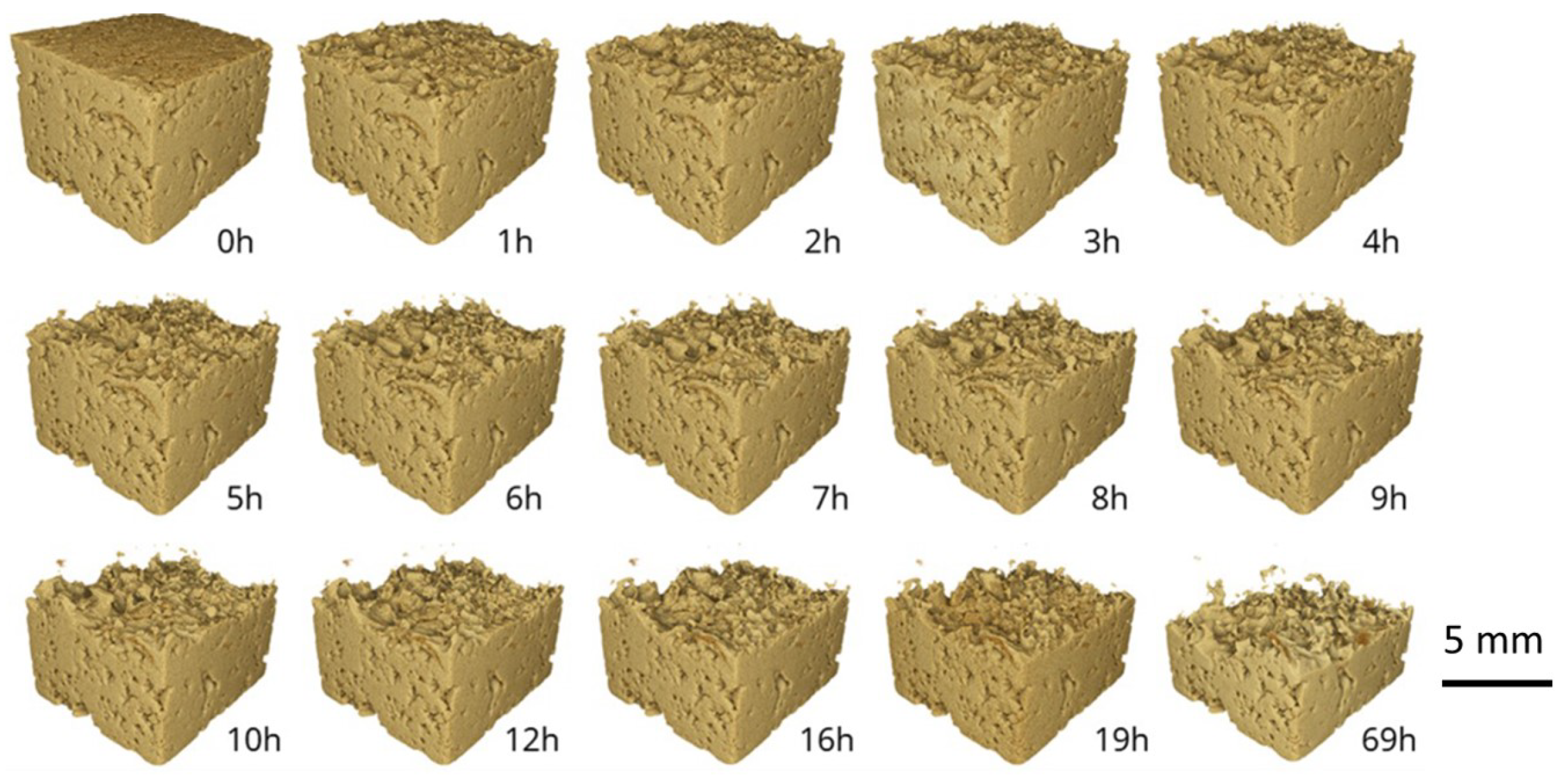
We investigated the dynamics of etching an epoxy impregnated sample by time-series X-ray CT scans, shown in Figure 15. We observed that the etching rate decreased rapidly with the sample thickness, i.e., the etching time of the first mm was 10 h, while it was 50 h for the second mm. The dissolution of calcite in acids is a rapid heterogeneous reaction [60], and Lund et al. [61] showed that, in strong acids like hydrochloric acid (HCl), the dissolution would only be limited by the diffusion of acid to the calcite surface and the reaction at the solid–liquid interface.
In pore casts, the pore space is filled with epoxy, and thus the sample tortuosity limits the rock surface area exposed to the acid. Moreover, the mass transfer of reactants and/or products slows the etching rate. Hence, the maximum etching rate will be observed at open boundaries of the sample, and the rate will decrease rapidly with the sample thickness. To have faster and more homogeneous etching, we mechanically cut slices with a 1-mm thickness where both upper and lower surfaces are not encapsulated by resin. In comparison to a few days for a 5-mm sample, the total etching time of a 1-mm slice was around 3 h.

3.3.3. Confocal Microscopy

Figure 16 illustrates the confocal images of the epoxy pore casts of Indiana limestone obtained from the high-pressure resin impregnation. Before impregnation, the rock sample was heated in an oven at 60 C for 12 h. Then, the sample was degassed under vacuum of 120 mbar for about 10 min, followed by pressurized resin impregnation at 65 bar for 36 h. We followed the procedure described in [62] to image of the etched epoxy pore casts of Indiana limestone with confocal microscopy. The samples were etched with dilute acid to dissolve the opaque rock matrix. This etching process rendered the residual pore cast more “transparent” to CLSM.
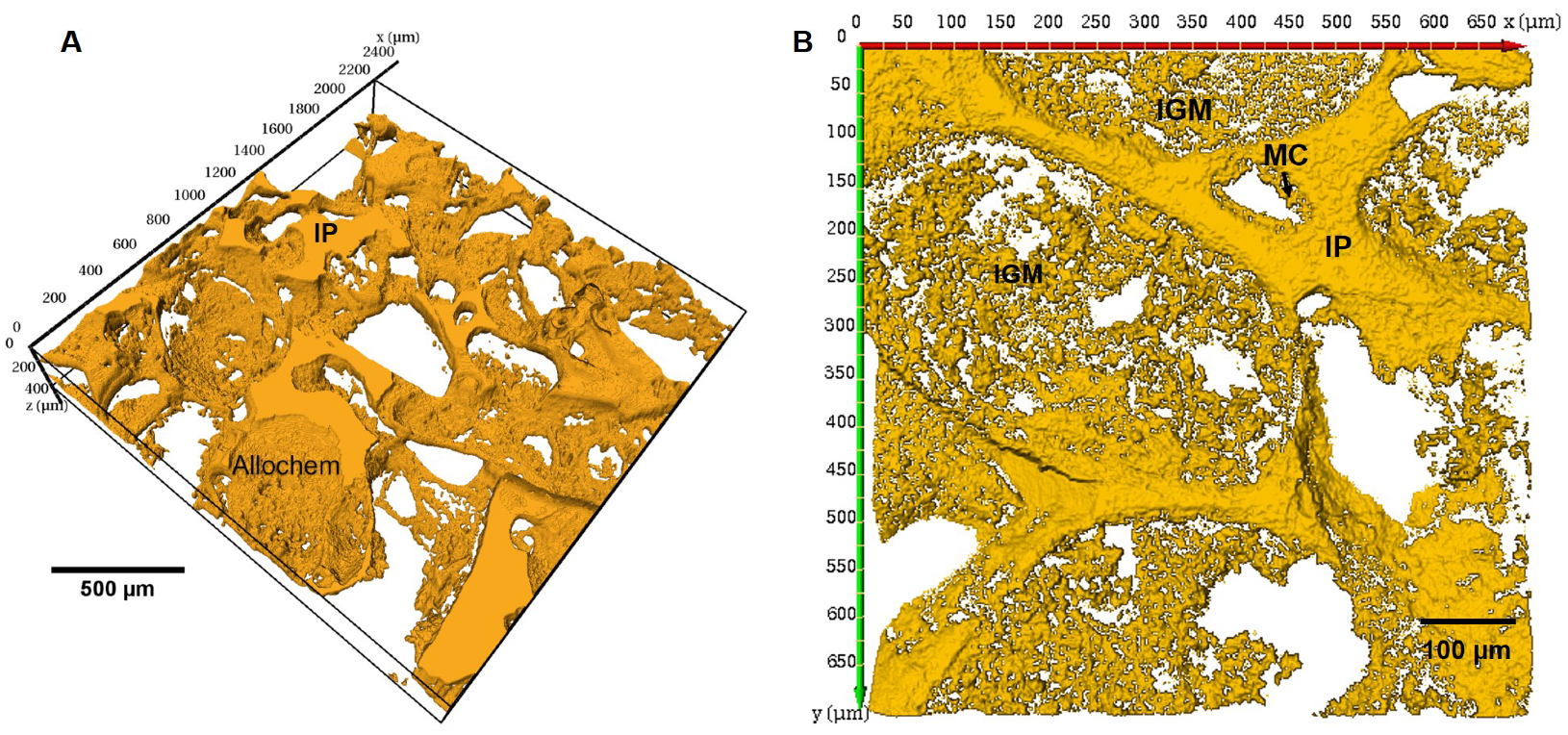
We achieved depths of investigation of up to a few hundreds of micrometers. The high-resolution 3D CLSM images of the pore cast helped to identify the allochems and the interparticle porosity (IP), which is made up of the relatively large pores shown in Figure 16A. The micrite cement (MC) coating the allochem rims along with the intergranular microporosity (IGM) were identified using the 20X-water immersion objective as shown in Figure 16B. These details were not observed in the microCT images, hence the importance of the 3D images acquired using CLSM.

4. Conclusions

In this study, we developed a protocol to evaluate the parameters of the resin impregnation procedure used to fabricate pore casts of porous materials. We used silicon micromodels as testing specimens to optimize the impregnation pressure, time, and resin viscosity, producing high-quality pore casts. Then, we used the optimized pore casting fabrication procedure to capture the complex pore space of micritic carbonates. Carbonate pore casting was accompanied by rock matrix etching for the casts to be suitable for high-resolution 3D confocal imaging.
From our silicon micromodel experiments, we identified a number of defects and artifacts that arose during the resin pore casting. Most of these defects can be attributed to resin shrinkage, which we think is generally underreported. In our work, we identified two types of shrinkage defects: voids formed within the resin and cracks developed across the resin structure. The shrinkage defects were found to be more aggressive when degassing was performed under higher vacuum levels or for a longer time. We also noted that diluting resin with solvents, such as toluene, to reduce the resin viscosity caused aggressive defects and deteriorated the optical and mechanical properties of the cured resin.
Pore cast etching is a critical prerequisite to capturing the high-quality 3D images of carbonates pore space. Thus, micro-CT scans validated our etching procedure by evaluating the porosity values of the pre- and post-etching sample. The micro-CT images also showed that some minor defects still persisted, but these defects represented only 0.21% of the sample’s pore volume.
In summary, the main outcome of this paper is a robust experimental procedure for obtaining high-quality epoxy pore casts of complex porous materials. We applied this procedure to characterize the pore space of micritic carbonates with confocal imaging.

Author Contributions

Conceptualization, T.P., M.Y. and A.H.; methodology, M.Y. and A.H.; software, A.H.; validation, A.H., V.C. and M.Y.; formal analysis, A.H. and M.Y.; investigation, A.H., M.Y. and V.C.; resources, T.P.; data curation, T.P.; writing—original draft preparation, A.H.; rewriting manuscript—review and editing, T.P., M.Y. and V.C.; visualization, A.H.; supervision, T.P., M.Y. and V.C.; project administration, T.P.; funding acquisition, T.P. All authors have read and agreed to the published version of the manuscript.

Funding

Ahmed Hassan (Ph.D. student) and Maxim Yutkin (Research Scientist) are supported by baseline research funding from KAUST to Tadeusz Patzek. Viswasanthi Chandra is supported by Ali I. Al-Naimi Petroleum Engineering Research Center (ANPERC) at KAUST.

Institutional Review Board Statement

Not applicable.

Informed Consent Statement

Not applicable.

Acknowledgments

We thank Marijn Boone from Tescan-XRE for acquiring the micro-CT images. We are grateful to the Nanofabrication Core Lab team at KAUST, especially to Ulrich Buttner and Ahad Syed, for their support in fabricating the silicon micromodels. KAUST has funded this project through the Ali I. Al-Naimi Petroleum Engineering Research Center (ANPERC).

Conflicts of Interest

The authors declare no conflict of interest.

Abbreviations

The following abbreviations are used in this manuscript:
CLSMConfocal Laser Scanning Microscopy
NANumerical Aperture
DRIEDeep Reactive Ion Etching
SCCMStandard Cubic Cm per Minute
MCMicritic Cement
MIPMercury Intrusion Porosimetry
IGMIntragranular Microporosity
Micro-CTMicro-Computed Tomography
IPInterparticle Porosity

References

  1. Waters, B.T.; Savage, D.E. Making duplicates of small vertebrate fossils for teaching and for re-search collections. Curator 1971, 14, 123–132. [Google Scholar] [CrossRef]
  2. Purnell, M.A. Casting, replication, and anaglyph stereo imaging of microscopic detail in fossils, with examples from conodonts and other jawless vertebrates. Palaeontol. Electron. 2003, 6, 1–11. [Google Scholar]
  3. Mihlbachler, M.C.; Foy, M.; Beatty, B.L. Surface replication, fidelity and data loss in traditional dental microwear and dental microwear texture analysis. Sci. Rep. 2019, 9, 1–13. [Google Scholar] [CrossRef] [Green Version]
  4. Jernvall, J.; Selänne, L. Laser confocal microscopy and geographic information systems in the study of dental morphology. Palaeontol. Electron. 1999, 2, 18. [Google Scholar] [CrossRef]
  5. Macdonald, D.A.; Harman, R.; Evans, A.A. Replicating surface texture: Preliminary testing of molding compound accuracy for surface measurements. J. Archaeol. Sci. Rep. 2018, 18, 839–846. [Google Scholar] [CrossRef]
  6. Waldo, A.W.; Yuster, S.T. Method of impregnating porous materials to facilitate pore studies. AAPG Bull. 1937, 21, 259–267. [Google Scholar]
  7. Pittman, E.D.; Duschatko, R.W. Use of pore casts and scanning electron microscope to study pore geometry. J. Sediment. Res. 1970, 40, 1153–1157. [Google Scholar]
  8. Wardlaw, N. Pore geometry of carbonate rocks as revealed by pore casts and capillary pressure. AAPG Bull. 1976, 60, 245–257. [Google Scholar]
  9. Yanguas, J.; Paxton, S.T. A new technique for preparation of petrographic thin sections using ultraviolet-curing adhesive. J. Sediment. Res. 1986, 56, 539–540. [Google Scholar] [CrossRef]
  10. Klaver, J.; Hemes, S.; Houben, M.; Desbois, G.; Radi, Z.; Urai, J. The connectivity of pore space in mudstones: Insights from high-pressure Wood’s metal injection, BIB-SEM imaging, and mercury intrusion porosimetry. Geofluids 2015, 15, 577–591. [Google Scholar] [CrossRef]
  11. Jobe, T.; Geiger, S.; Jiang, Z.; Agar, S. Micropore network modelling from 2D confocal imagery: Impact on reservoir quality and hydrocarbon recovery. Pet. Geosci. 2018, 24, 323–334. [Google Scholar] [CrossRef]
  12. Cantrell, D.L.; Hagerty, R.M. Microporosity in arab formation carbonates, Saudi Arabia. GeoArabia 1999, 4, 129–154. [Google Scholar]
  13. Morrow, N.R.; Buckley, J. Wettability and Oil Recovery by Imbibition and Viscous Displacement from Fractured and Heterogeneous Carbonates; Chemical & Petroleum Engineering, University of Wyoming: Laramie, WY, USA, 2006. [Google Scholar]
  14. Fullmer, S.M.; Guidry, S.A.; Gournay, J.; Bowlin, E.; Ottinger, G.; Al Neyadi, A.; Gupta, G.; Gao, B.; Edwards, E. Microporosity: Characterization, distribution, and influence on oil recovery. In Proceedings of the IPTC 2014: International Petroleum Technology Conference, Doha, Qatar, 19–22 January 2014. [Google Scholar]
  15. Minoura, N.; Conley, C. Technique for impregnating porous rock samples with low-viscosity epoxy resin. J. Sediment. Res. 1971, 41, 858–861. [Google Scholar] [CrossRef]
  16. John, D.S. The use of large-area thin sectioning in the petrographic examination of concrete. In Petrography Applied to Concrete and Concrete Aggregates; ASTM International: West Conshohocken, PA, USA, 1990. [Google Scholar]
  17. Smith, S.J.; Anderson, R.S. A method for impregnating soft sediment cores for thin-section microscopy. J. Sediment. Res. 1995, 65, 576–577. [Google Scholar] [CrossRef]
  18. Hurst, A.; Nadeau, P.H. Clay microporosity in reservoir sandstones: An application of quantitative electron microscopy in petrophysical evaluation. AAPG Bull. 1995, 79, 563–573. [Google Scholar]
  19. Chen, J.; Zampini, D.; Walliser, A. High-pressure epoxy-impregnated cementitious materials for microstructure characterization. Cem. Concr. Res. 2002, 32, 1–7. [Google Scholar] [CrossRef]
  20. Beckett, D.; Sellwood, B. A simple method for producing high-quality porecasts of carbonate rocks. Sediment. Geol. 1991, 71, 1–4. [Google Scholar] [CrossRef]
  21. Camuti, K.S.; McGuire, P.T. Preparation of polished thin sections from poorly consolidated regolith and sediment materials. Sediment. Geol. 1999, 128, 171–178. [Google Scholar] [CrossRef]
  22. Boës, X.; Fagel, N. Impregnation method for detecting annual laminations in sediment cores: An overview. Sediment. Geol. 2005, 179, 185–194. [Google Scholar] [CrossRef]
  23. Kjellsen, K.; Monsøy, A.; Isachsen, K.; Detwiler, R. Preparation of flat-polished specimens for SEM-backscattered electron imaging and X-ray microanalysis importance of epoxy impregnation. Cem. Concr. Res. 2003, 33, 611–616. [Google Scholar] [CrossRef]
  24. Soeder, D.J. Applications of Fluorescence Microscopy to Study of Pores in Tight Rocks. AAPG Bull. 1990, 74, 30–40. [Google Scholar]
  25. Spurr, A.R. A low-viscosity epoxy resin embedding medium for electron microscopy. J. Ultrastruct. Res. 1969, 26, 31–43. [Google Scholar] [CrossRef]
  26. Head, M.; Buenfeld, N. Confocal imaging of porosity in hardened concrete. Cem. Concr. Res. 2006, 36, 896–911. [Google Scholar] [CrossRef]
  27. Shah, S.; Crawshaw, J.; Boek, E. Preparation of microporous rock samples for confocal laser scanning microscopy. Pet. Geosci. 2014, 20, 369–374. [Google Scholar] [CrossRef]
  28. Jim, C. Impregnation of moist and dry unconsolidated clay samples using Spurr resin for microstructural studies. J. Sediment. Res. 1985, 55, 597–599. [Google Scholar] [CrossRef]
  29. Yadav, G.; Dullien, F.; Chatzis, I.; Macdonald, I. Microscopic distribution of wetting and nonwetting phases in sandstones during immiscible displacements. SPE Reserv. Eng. 1987, 2, 137–147. [Google Scholar] [CrossRef]
  30. Rothwell, R.G.; Rack, F.R. New techniques in sediment core analysis: An introduction. Geol. Soc. Lond. Spec. Publ. 2006, 267, 1–29. [Google Scholar] [CrossRef] [Green Version]
  31. Muller, M. Introduction to Confocal Fluorescence Microscopy; SPIE Press: Bellingham, WA, USA, 2006; Volume 69. [Google Scholar]
  32. Pawley, J. Handbook of Biological Confocal Microscopy; Springer: Berlin/Heidelberg, Germany, 2010. [Google Scholar]
  33. Fredrich, J.; Menendez, B.; Wong, T.F. Imaging the pore structure of geomaterials. Science 1995, 268, 276–279. [Google Scholar] [CrossRef]
  34. Petford, N.; Davidson, G.; Miller, J. Investigation of the petrophysical properties of a porous sandstone sample using confocal scanning laser microscopy. Pet. Geosci. 2001, 7, 99–105. [Google Scholar] [CrossRef]
  35. Fredrich, J. 3D imaging of porous media using laser scanning confocal microscopy with application to microscale transport processes. Phys. Chem. Earth Part A Solid Earth Geod. 1999, 24, 551–561. [Google Scholar] [CrossRef] [Green Version]
  36. Hsieh, J. Computed Tomography: Principles, Design, Artifacts, and Recent Advances, 3rd ed.; SPIE: Bellingham, WA, USA, 2015. [Google Scholar]
  37. Withers, P.J.; Bouman, C.; Carmignato, S.; Cnudde, V.; Grimaldi, D.; Hagen, C.K.; Maire, E.; Manley, M.; Du Plessis, A.; Stock, S.R. X-ray computed tomography. Nat. Rev. Methods Prim. 2021, 1, 1–21. [Google Scholar]
  38. Sánchez, S.; Narciso, J.; Rodríguez-Reinoso, F.; Bernard, D.; Watson, I.; Lee, P.; Dashwood, R. Characterization of Lightweight Graphite Based Composites Using X-Ray Microtomography. Adv. Eng. Mater. 2006, 8, 491–495. [Google Scholar] [CrossRef]
  39. Salvo, L.; Suéry, M.; Marmottant, A.; Limodin, N.; Bernard, D. 3D imaging in material science: Application of X-ray tomography. C. R. Phys. 2010, 11, 641–649. [Google Scholar] [CrossRef]
  40. Lärmer, F.; Schilp, A. Verfahren zum anisotropen Ätzen von Silizium. Dtsch. Pat. DE 1994, 42, 045. [Google Scholar]
  41. Cañamero-Martínez, P.; Fernández-García, M.; De la Fuente, J.L. Rheological cure characterization of a polyfunctional epoxy acrylic resin. React. Funct. Polym. 2010, 70, 761–766. [Google Scholar] [CrossRef]
  42. Patton, J.B.; Carr, D.D. The Salem Limestone in the Indiana Building-Stone District; Technical Report; Indiana Geological Survey: Indianapolis, IN, USA, 1982. [Google Scholar]
  43. Churcher, P.; French, P.; Shaw, J.; Schramm, L. Rock properties of Berea sandstone, Baker dolomite, and Indiana limestone. In Proceedings of the SPE International Symposium on Oilfield Chemistry, Anaheim, CA, USA, 20–22 February 1991. [Google Scholar]
  44. Vajdova, V.; Baud, P.; Wu, L.; Wong, T.f. Micromechanics of inelastic compaction in two allochemical limestones. J. Struct. Geol. 2012, 43, 100–117. [Google Scholar] [CrossRef]
  45. Caccia, M.; Camarano, A.; Sergi, D.; Ortona, A.; Narciso, J. Wetting and Navier-Stokes equation—The manufacture of composite materials. Wetting Wettability 2015, 2015, 105–137. [Google Scholar]
  46. Shah, S.M.K. Multi-Scale Imaging of Porous Media and Flow Simulation at the Pore Scale. Ph.D. Thesis, Imperial College London, London, UK, 2014. [Google Scholar]
  47. Szekely, J.; Neumann, A.; Chuang, Y. The rate of capillary penetration and the applicability of the Washburn equation. J. Colloid Interface Sci. 1971, 35, 273–278. [Google Scholar] [CrossRef]
  48. Maija Leskinen, A. Layer structure in model coatings. Tappi J. 1987, 70, 101–106. [Google Scholar]
  49. Marmur, A. Penetration and displacement in capillary systems of limited size. Adv. Colloid Interface Sci. 1992, 39, 13–33. [Google Scholar] [CrossRef]
  50. Pesse, A.V.; Warrier, G.R.; Dhir, V.K. Experimental study of the gas entrapment process in closed-end microchannels. ASME Int. Mech. Eng. Congr. Expo. 2004, 4711, 119–128. [Google Scholar]
  51. Hamraoui, A.; Nylander, T. Analytical approach for the Lucas—Washburn equation. J. Colloid Interface Sci. 2002, 250, 415–421. [Google Scholar] [CrossRef]
  52. Dudgeon, A. Penetration of Surfactant Solutions into Capillaries. Ph.D. Thesis, Durham University, Durham, UK, 2011. [Google Scholar]
  53. Ramos, J.; Pagani, N.; Riccardi, C.; Borrajo, J.; Goyanes, S.; Mondragon, I. Cure kinetics and shrinkage model for epoxy-amine systems. Polymer 2005, 46, 3323–3328. [Google Scholar] [CrossRef]
  54. Plepys, A.; Farris, R. Evolution of residual stresses in three-dimensionally constrained epoxy resins. Polymer 1990, 31, 1932–1936. [Google Scholar] [CrossRef]
  55. Eom, Y.; Boogh, L.; Michaud, V.; Sunderland, P.; Månson, J.A. Stress-initiated void formation during cure of a three-dimensionally constrained thermoset resin. Polym. Eng. Sci. 2001, 41, 492–503. [Google Scholar] [CrossRef]
  56. Thomas, S.; Bongiovanni, C.; Nutt, S. In situ estimation of through-thickness resin flow using ultrasound. Compos. Sci. Technol. 2008, 68, 3093–3098. [Google Scholar] [CrossRef]
  57. Potter, K. Resin Transfer Moulding; Springer: Berlin/Heidelberg, Germany, 2012. [Google Scholar]
  58. Gündüz, G.; Yeter, B.; Tuğlu, P.; Ahmed, I. Styrene-acrylonitrile co-polymer impregnated mortar. J. Mater. Sci. 1981, 16, 221–225. [Google Scholar] [CrossRef]
  59. Gündüz, G.; Yalçin, N. Strength of steel-fibre-reinforced polymer concrete: Effect of impregnation technique. Compos. Sci. Technol. 1987, 30, 127–135. [Google Scholar] [CrossRef]
  60. Langmuir, D. Stability of calcite based on aqueous solubility measurements. Geochim. Cosmochim. Acta 1968, 32, 835–851. [Google Scholar] [CrossRef]
  61. Lund, K.; Fogler, H.S.; McCune, C.; Ault, J. Acidization–II. The dissolution of calcite in hydrochloric acid. Chem. Eng. Sci. 1975, 30, 825–835. [Google Scholar] [CrossRef] [Green Version]
  62. Hassan, A.; Chandra, V.; Yutkin, M.P.; Patzek, T.W.; Espinoza, D. Imaging and Characterization of Microporous Carbonates Using Confocal and Electron Microscopy of Epoxy Pore Casts. SPE J. 2019, 24, 1–220. [Google Scholar] [CrossRef]
Figure 1. The fabricated micromodels used to study the epoxy impregnation parameters. (A) Two patterns engraved in silicon micromodels. (B) The sintered glass beads inside a 1-mm square glass capillary imaged with an optical microscope.
Applsci 11 05557 g001
Figure 2. Resin viscosity vs. time. The gelation behavior was measured with a viscometer, under an average shear rate of 4 s 1 , for 3–4 h, and Equation (1) was fitted to extrapolate the behavior. The viscosity was measured for four resin and toluene (tol.) compositions: (a) pure resin, (b) resin + 5 wt.% tol., (c) resin + 10 wt.% tol., and (d) resin + 30 wt.% tol. The composition (d) experienced viscosity reduction of almost 15 times; however, the curing time nearly doubled, and the mechanical properties greatly suffered.
Applsci 11 05557 g002
Figure 3. Pore throat size distribution based on the MIP data represented by a plot of the log-differential of mercury volume intrusion (mg/L) vs. the pore throat diameter (µm).
Applsci 11 05557 g003
Figure 4. The equipment used for resin impregnation. (A) The desiccator with a tilting handle used for degassing the sample and epoxy separately when connected to a vacuum source. (B) High pressure vessel connected to high pressure gas line.
Applsci 11 05557 g004
Figure 5. Visualization of Equation (5) for impregnating Indiana limestone with epoxy at three different pressures: P i m p r e g = 0 bar (case I), P i m p r e g = 1 bar (case II, vacuum), and P i m p r e g = 65 bar (case III). In case I, the flow is driven only by capillary forces, while in cases II and III, P i m p r e g consists of capillary pressure and applied overpressure. The advantage of pressure-assisted impregnation (case III) is an order of magnitude higher than that of the other cases.
Applsci 11 05557 g005
Figure 6. Confocal images of the micromodels impregnated by resin under two vacuum levels: (A) 10 mbar, and (B) 120 mbar. Type 1 defects, trapped gas, are more abundant in model B due to the inefficient degassing and impregnation energy. Type 2 shrinkage defects are more abundant in model A, because the epoxy resin is more aggressively vaporized. Type 2A refers to void shrinkage defects, while type 2B refers to cracks.
Applsci 11 05557 g006
Figure 7. Confocal images of type 2 shrinkage defects: (A) The voids in the resin that have 10–40 µm size. (B) The rough shrinkage cracks that develop across the structure indicate high residual shrinkage stresses.
Applsci 11 05557 g007
Figure 8. Confocal images of silicon micromodels impregnated by resin mixed with a fluorescent dye. Impregnation is carried out at: vacuum (A) and at high pressure (B). Type 1 defects (gas bubbles) trapped during the inefficient impregnation are highlighted inside the channels of both micromodels. Type 2 defects were only observed in the high-pressure impregnated model.
Applsci 11 05557 g008
Figure 9. Confocal image of the silicon micromodel impregnated by resin mixed with fluorescent dye under high pressure preceded bya degassing step at a low vacuum level, 120 mbar. No trapped gases were observed even at the smallest channel, which shows the importance of the degassing step, while type 2 shrinkage defects were still persistent but with less severity due to the lower vacuum level used at the degassing step.
Applsci 11 05557 g009
Figure 10. Confocal images of two types of the micromodels impregnated with resin under high pressure (65 bar) released to atmospheric pressure before complete curing took place. (A) Silicon micromodel, and (B) sintered glass beads. Defects in both models occurred when nitrogen gas dissolved at 65 bar was abruptly released when the pressure was dropped to atmospheric and the resin was incompletely cured. The gas release in model B was severe enough to debond some of the sintered glass beads.
Applsci 11 05557 g010
Figure 11. Estimated lengths of impregnation penetration into Indiana limestone versus time. Three resin and toluene (tol.) compositions were tested: (a) pure resin, (b) resin + 5% tol., and (c) resin + 30% tol. Both vacuum and high pressure impregnation schemes were considered for all compositions. The resin penetration length did not change significantly unless the toluene content was more than 30%; however, the mechanical properties for this composition greatly deteriorated.
Applsci 11 05557 g011
Figure 12. Confocal images of two micromodels impregnated under a vacuum. Two compositions of resin and toluene were used: (A) epoxy mixed with 5% toluene and (B) epoxy mixed with 30% toluene. In model A, a phase boundary between toluene and epoxy was detected. Shrinkage defects, especially type 2A, were visibly more abundant in model B where the toluene fraction was higher.
Applsci 11 05557 g012
Figure 13. The micro-CT image of the Indiana limestone sample impregnated with epoxy. This grayscale image is but one of the 943 slices representing the 5.1-mm sample thickness. The sample is composed mainly of allochems as indicated; however, the microporosity geometry can hardly be identified at the resolution of 5.41 µm per voxel. Defects, such as the highlighted type 2A shrinkage defect, could still be identified in the impregnated sample. They represent only 0.21% of the pore volume. Colors are assigned to different grayscale values to aid visualization. The color code indicates the different elements of the image.
Applsci 11 05557 g013
Figure 14. Two micro-CT scans of resin impregnated sample pre-etching (left) and post-etching (right) the rock matrix with hydrochloric acid. Color coding based on threshold segmentation was used to identify rock matrix (grey), and resin (green).
Applsci 11 05557 g014
Figure 15. Time-series of micro-CT scans of an epoxy impregnated sample etched with 0.5 M HCl. Only the rock matrix is represented in the 3D images by solid (yellow) to detect the evolution of the acid etching process, while the resin was digitally removed. The scans show that dissolution rate of deeper pats of the impregnated sample was significantly slower compared to the upper parts.
Applsci 11 05557 g015
Figure 16. Confocal images of the etched epoxy pore cast of Indiana limestone, where the solid represents the pore space and the etched away grains are white. Sample (A) was imaged with the 10× air objective and the resolution of 1.6 µm per pixel for the total size of 2.3 mm × 2.3 mm × 0.33 mm. Sample (B) was imaged with the 20× water immersion objective and the resolution of 0.34 µm per pixel for the total size of 0.7 mm × 0.7 mm × 0.9 mm. The higher resolution CLSM images allowed detecting types of microporosity: the micritic intragranular microporosity (IGM) can be seen within the grains. The micrite cement (MC) can be seen along the rims of allochems. The inter-particle (IP) pores are the relatively large voids at the junctions of the allochems.
Applsci 11 05557 g016
Table 1. DRIE parameters for etching patterns into silicon models.
ParameterPassivationEtching
ICP Power1300 Watts
Pressure30 mTorr
Temperature 20 C
C4F8 flow rate100 SCCM *5 SCCM
SF6 flow rate5 SCCM100 SCCM
* Standard Cubic Cm per Minute.
Table 2. Epoxy resin properties.
Epoxy Resin
Density1118 kg/m 3
Viscosity0.468 Pa · s
Surface tension0.039 N/m
Contact-angle on silica31
Curing agentPrimary amine
Curing time *24–36 h *
Curing temperature25 C
* Curing time is pressure-dependent.
Table 3. Types of defects observed in resin-impregnated micromodels.
Defect TypeDescription
Type 1Trapped gases
Type 2Shrinkage defects
Type 2AVoids with corrugated boundaries and irregular shapes
Type 2BRough cracks
Table 4. Epoxy pore casting of Indiana limestone.
Impregnation Parameters
Degassing80 mbar
Degassing time30 min
Impregnation pressure65 bar
Curing time30 h
Resin viscosity0.468 Pa · s
Temperature25 C
Publisher’s Note: MDPI stays neutral with regard to jurisdictional claims in published maps and institutional affiliations.