Article

Interdisciplinary Learning Methodology for Supporting the Teaching of Industrial Radiology through Technical Drawing

1
Department of Mechanical Engineering, Catholic University of Ávila, 05005 Ávila, Spain
2
Construction Department, University of Salamanca, 49029 Zamora, Spain
3
Computer Science and Automatics, University of Salamanca, 37008 Salamanca, Spain
4
Department of Mechanical Engineering, ETSII, Avda. Fernando Ballesteros, 2, 37700 Béjar, Spain
*
Author to whom correspondence should be addressed.
Appl. Sci. 2021, 11(12), 5634; https://doi.org/10.3390/app11125634
Submission received: 14 April 2021 / Revised: 25 May 2021 / Accepted: 17 June 2021 / Published: 18 June 2021
(This article belongs to the Special Issue Engineering Applied to Sustainable Development Goals)

Abstract

:
Technical drawing (TD) is a subject frequently perceived by engineering students as difficult and even lacking in practical application. Different studies have shown that there is a relationship between studying TD and improvement of spatial ability, and there are precedents of works describing successful educational methodologies based on information and communications technology (ICT), dedicated in some cases to improving spatial ability, and in other cases to facilitating the teaching of TD. Furthermore, interdisciplinary learning (IL) has proven to be effective for the training of science and engineering students. Based on these facts, this paper presents a novel IL educational methodology that, using ICT-based tools, links the teaching of industrial radiology with the teaching of TD, enhancing the spatial ability of students. First, the process of creating the didactic material is described in summary form, and thereafter, the way in which this educational methodology is implemented in the classroom. Finally, we analyze how the use of ICT-based didactic tools such as the one described in this paper can contribute to the achievement of the sustainable development goals set out in the 2030 Agenda of the United Nations.

1. Introduction

The subject of technical drawing (TD) is present in the program of many engineering courses due to the importance it will have throughout the development of the professional activity of many future engineers. However, TD is considered by a large number of students as a difficult subject to pass [1,2], besides being sometimes perceived as a subject without many practical applications [3]. These facts lead many students to feel discouraged and unmotivated to study TD. Different studies have analyzed the relationship between TD and the spatial visualization skills that students have, and how learning the former can lead to an improvement in the latter. The work of Contreras et al. [4] points out that the study of subjects such as TD, geometry, or graph analysis (among others) results in an indirect training of spatial ability. Mendez et al. [5] found that TD first-year engineering students who studied TD during their pre-university studies presented better visual discrimination and spatial memory than university philology students, who had not studied TD previously. Studies conducted by Ogunkola and Knight involving secondary school students concluded that there are significant positive effects of technical drawing on spatial visualization and orientation [6,7].
On another note, it is increasingly common to resort to the use of information and communications technology (ICT) to assist in the teaching–learning process of disciplines that by their very nature may be difficult for many students to understand [8,9,10,11,12,13]. Thus, the use of ICT has proven to be effective in improving the spatial ability of science and engineering students through different technological solutions, such as augmented reality [14], non-immersive virtual reality [15,16,17], web-based learning tools [18], PDF-3D [19], etc. Likewise, TD teaching has also benefited from the use of new technologies, as evidenced by the existence of several works in which different solutions based on the use of ICT were shown to support the teaching–learning process of this discipline [3,7,14,18,20,21,22,23].
Mansilla et al. [24] defined interdisciplinary understanding as the capacity to integrate knowledge and modes of thinking in two or more disciplines or established areas of expertise to produce a cognitive advancement, such as explaining a phenomenon, solving a problem, or creating a product, in ways that would have been impossible or unlikely through single disciplinary means. Interdisciplinary learning, which is not additive but integrative in nature, results in the student acquiring the ability to think in an interdisciplinary way [25]. This interdisciplinary thinking is a complex cognitive ability that allows changing disciplinary perspectives and creating meaningful connections between disciplines [25,26].
Interdisciplinary teaching methodologies have been the subject of a multitude of works that indicated their suitability when applied to the training of students in the areas of science and engineering [27]. One example is the work of Borrego et al. [28], which describes the implementation of a rural interdisciplinary health care training program oriented to pharmacy students, in which disciplines such as pharmacy, medicine, nursing, and dental hygiene, among others, were represented. Another example is the article by Harrison et al. [29], which describes an interdisciplinary hydropower design course in which electrical, mechanical, and civil engineering were intertwined. The work of Furlan et al. [30] is another example of an interdisciplinary teaching project that, in addition, has the particularity of uniting disciplines as apparently different as chemistry, humanities, and English. Reviewing the existing literature, it can be seen that interdisciplinary learning (IL) is a widespread teaching methodology which, when applied to engineering, allows a closer connection between the teaching–learning process and the situations that the student will encounter in the real world [27].
Moreover, radiological testing is one of the most widely used non-destructive tests (NDT) in the industrial sector to detect imperfections inside metal parts, and its teaching is often part of mechanical engineering programs, particularly in the materials science and engineering (MSE) courses. These tests consist of radiating a part or part of it, obtaining as a result a 2D image that is subsequently analyzed to detect possible imperfections or poorly welded areas (e.g., porosity, burn thru, lack of penetration, internal and external undercuts, lack of fusion, etc.) [31]. The student starting in this field must be able to place the imperfections observed in the 2D radiography in the real 3D part analyzed, which can be complicated for students who do not have adequate spatial ability [32,33,34]. For this reason, it is appropriate to teach industrial radiology by facilitating students’ spatial understanding of defects observed in radiographies through interdisciplinary teaching [3].
In the field of industrial radiology there are already methods that take advantage of the potential of ICT to analyze welding defects [35,36,37], in many cases applying them in educational environments [38,39]. Therefore, in focus with sustainable goals, the use of ICT can avoid the use of real radiation emissions by using virtual environments. Thus, taking advantage of the possibilities of 3D imaging offered by ICT, as well as the effectiveness that interdisciplinary teaching has demonstrated in other fields of science and engineering, this paper presents a new methodology for teaching industrial radiology focused on mechanical engineering students. The authors have not found research papers describing an educational methodology similar to the one described in this article, which is based on IL and creating an interdisciplinary didactic link between both subjects, TD and MSE. Hence, in the TD subject students must complete exercises consisting of obtaining the orthogonal views of a part (plant, elevation, and profile), while in the MSE subject students must identify internal defects of parts by using radiographs and based on the grayish coloration they observe in them. The didactic link between both subjects (TD and MSE) is established through certain exercises in which students analyze orthogonal views of the radiographed part to understand the shape and position of its internal defects. The implementation of this methodology allows students to improve their spatial ability for learning industrial radiology contents, establishing at the same time a didactic link with TD.
In this way, students find a greater motivation for the TD subject by perceiving and assimilating a direct application of this subject in their future professional life as engineers. Therefore, this article presents a multidisciplinary methodology for both subjects, TD and MSE, based on the simulation of radiographs of welded parts with imperfections. Since the authors have not found any similar examples in the scientific literature, this article presents the technical process of designing these type of radiographs to make them look as real as possible, so that the reader can reproduce this experience if necessary.

2. Theoretical Background of Industrial Radiology

According to the American Society for Nondestructive Testing (ASNT), an NDT is defined as “the determination of the physical condition of an object without affecting that object’s ability to fulfill its intended function” [40]. There are five basic NDT methods, which are based respectively on the use of magnetic particles, penetrating fluids, radiography (X-rays or gamma-rays), and ultrasonic and eddy currents [41]. NDT based on radiography has a widespread presence in industry, being especially important, for example, in the inspection of the welded joints of pressure pipes and vessels [42]. Industrial radiology is based on applying a penetrating radiation (usually X or gamma-rays) to a part, which is placed between the radiation source and a detector or radiographic film on which the radiography is printed [41]. In this way, the radiography obtained is an orthogonal image of the piece colored in gray scale. The grayish coloration of each zone of the image depends on the radiation density, the width of the inspected object, and its chemical composition. Thus, if the radiation beam does not encounter any obstacles in its path it will reach the sensor or film with almost the same intensity as was generated at the source, creating a dark image; conversely, if the radiation beam passes through an obstacle it will reach the sensor or film with its intensity reduced, creating a light image. Using this phenomenon, it is possible to detect in a radiograph which areas of a part are formed only by the base material and which have defects inside. Defects such as cracks, voids, blowholes, or internal cavities, which are areas with lower radiation absorption than the base material, appear on radiographies as darker areas than the surrounding base material. Similarly, defects such as refractory inclusions absorb a different amount of radiation than the base material and therefore appear as areas of a different shade of gray than the base material.
The intensity reaching the sensor or film is quantified by the Beer–Lambert equation:
I = I 0 e μ x = I 0 e μ m ρ x
where I is the intensity of the radiation beam reaching the sensor or film, I0 is the intensity reaching the part, μ is the linear absorption coefficient, μm is the mass absorption coefficient, ρ is the density of the material, and x is the thickness of the material traversed by the radiation beam. Since μ depends on the type of material, the intensity of the beam that manages to pass through a part will have one value or another, depending on whether or not it has encountered internal defects on its way through the part, since the absorption coefficient of the defects is different from that of the base material that surrounds them.
The student who faces the study of industrial radiology must be able to analyze the different shades of gray observed in a radiograph in order to understand: (i) which zones correspond to the base material of the part; (ii) identify the internal defects of the part; (iii) spatially locate the identified defects; and (iv) classify the types of defects.

3. Interdisciplinary Learning

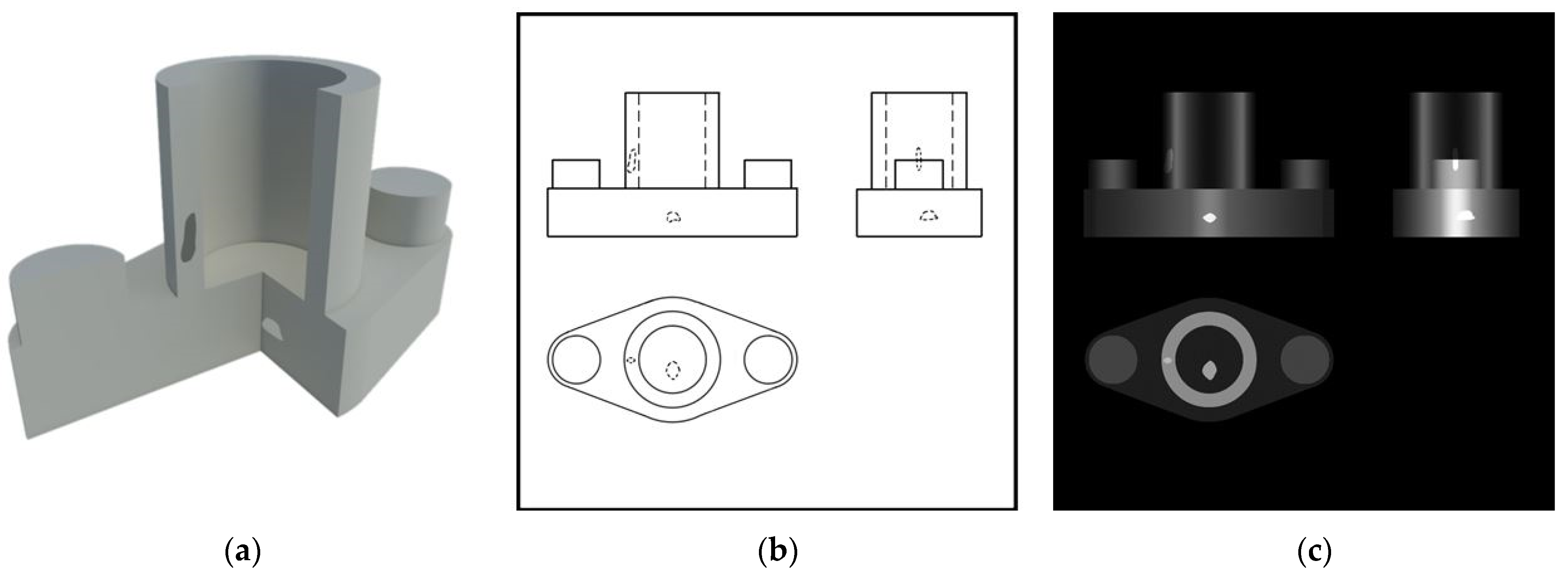
The analysis of the gray gradient of a radiograph is not trivial and presents certain difficulties that the methodology presented in this article tries to help overcome. This methodology, which takes advantage of the didactic link between TD and industrial radiology, is based on obtaining orthogonal views of a virtual part (plant, elevation, and profile) from radiographic images of that part simulated by software. As an example, Figure 1a shows a virtual part in three dimensions, while Figure 1b,c show the orthogonal views of the part (TD approach). In particular, Figure 1b shows the three orthogonal views delineated according to the TD norms, while Figure 1c shows the same three orthogonal views colored with different shades of gray depending on the thickness of each zone of the part. Note that Figure 1c simulates a simplified radiograph, i.e., it shows the edges of the part well defined (unlike in real radiographies, where the edges are blurred).
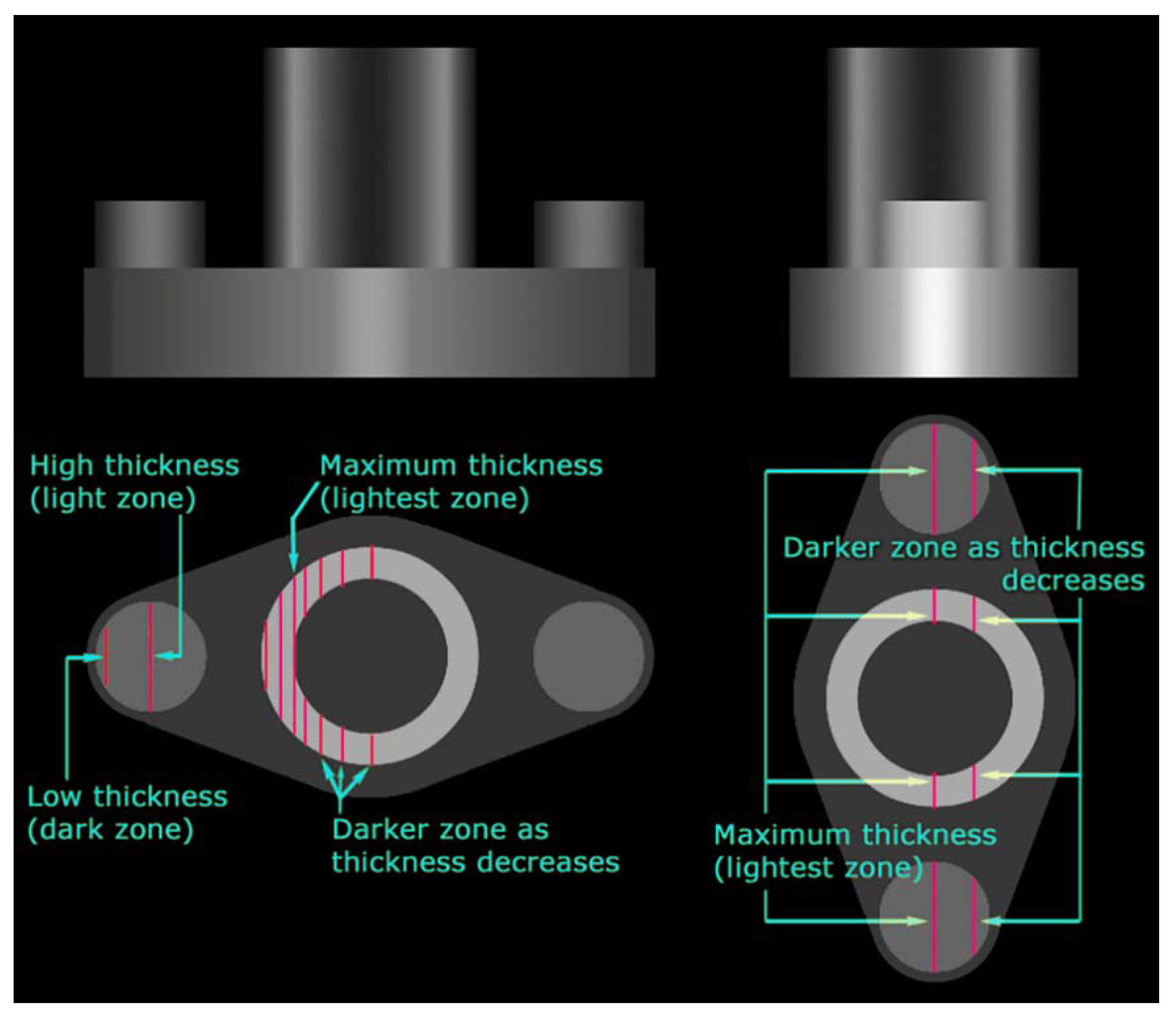
Through the view shown in Figure 1c, students can understand how the thickness of each zone of the part creates the different shades of gray shown, as per the Beer–Lambert equation. For example, in the elevation and side view of Figure 1c (located at the top of the Figure 1c) one can easily see in the cylinders of the part the influence that thickness has on the grayish coloration of the simplified radiograph. In fact, both in the elevation and profile views it is observed that the parts closer to the hollow axis of the central cylinder have a darker shade (since the radiation finds less base material to impede its passage and reaches the sensor or film with greater intensity) than in the areas closer to the center of the cylinder walls (since in these areas the radiation must pass through a greater amount of material and therefore reaches the sensor or film with less intensity). It is observed that the opposite phenomenon occurs in the two solid cylinders located on the sides of the part, in which the center is lighter in color (since the radiation beam passes through a larger amount of base material) than the ends (where the beam passes through a smaller amount of base material). Figure 2 explains graphically the gray gradient in the horizontal direction, and it is easily understood that the gray gradient of the cylinders is directly related to the thickness of the part in each zone crossed by the radiation beam.
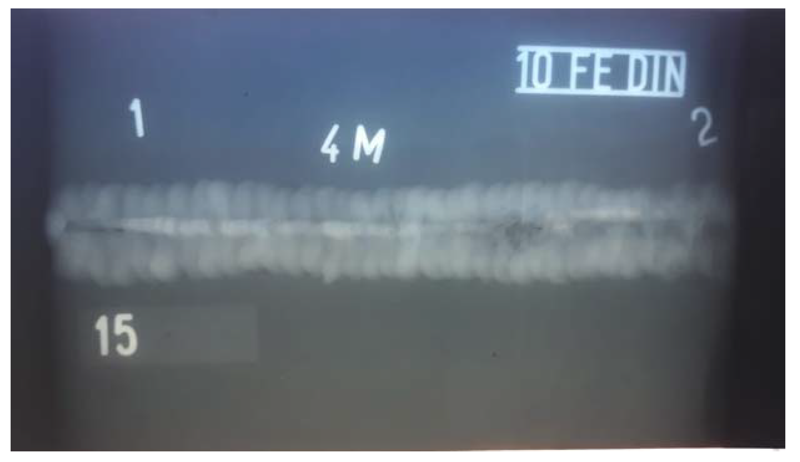
Figure 1c and Figure 2 show a simplified radiograph of a virtual part whose interior is homogeneous and free of inclusions or internal defects. The boundaries of the part can be easily identified and, by means of the gray gradient, the thickness of each zone of the part can be qualitatively estimated thanks to the ratio between the thickness of material passed through by the radiation beam in a given direction and the intensity of the radiation captured in the radiography. It is also possible to include internal defects in the virtual part, as shown in Figure 3, which allows students to use their knowledge of TD and industrial radiology to understand what they see in the radiographs. Following this process, it is possible to design exercises similar to real engineering problems that arise in industry, such as the inspection of internal defects in parts or welds (which are usually very difficult for students to understand and interpret). As an example of the radiographies used in inspections, a real X-ray is shown in Figure 4, thereby illustrating the complexity of interpreting industrial radiographs for students who are new to this activity. Thus, vermicular pores and lack of fusion are shown in this real X-ray radiograph of metallic welding, shown in Figure 4. This type of exercise that is similar to real problems makes it easier for students to appreciate that there is a direct application of what they are studying in their professional future. Figure 3 shows a virtual part, inside of which two inclusions of different shapes are housed. This image (Figure 3) is a useful tool for students to train and improve their spatial visualization skills, since they must analyze the shape, size, and position in space of the internal defects shown in the orthogonal views of the simplified radiograph (Figure 3c).

4. Interactive Virtual Platform

This paper presents an interactive virtual platform (IVP, Figure 5) that aims to improve students’ spatial vision skills while learning industrial radiology. The IVP allows students to interact in real time with three-dimensional virtual parts, it being possible to rotate them, change the point of view, etc. In addition, the IVP allows students to view opaque (Figure 5a) or translucent (Figure 5b) parts to visualize their internal defects.
In this way, through spatial understanding of the analyzed parts (IVP helps to identify the position and shape of internal defects) the students’ spatial visualization skills are trained. The use of IVP to analyze the presence of internal defects of a part involves different aspects: (i) spatial visualization skills; (ii) application of the theoretical background, supported by the equation of Beer–Lambert, to analyze the radiographies in terms of gray gradient; and (iii) the use of real engineering problems (in this case, the radiographic inspection of industrial parts).
The IVP described here helps students to appreciate the usefulness of the knowledge acquired for their future professional careers, thus increasing their motivation and improving the teaching–learning process.

5. Creation of Didactic Material

The methodology used for the creation of the didactic material, illustrated in Figure 6, consisted of three distinct phases: (i) development of 2D drawings; (ii) preparation of radiographic images (both simplified for initial application, and realistic (Figure 7) for a higher level of difficulty); and (iii) development of the IVP. Since there is no specific program that directly simulates the appearance of a radiographic part, this article describes how the authors achieved this effect.
During the first phase, two-dimensional drawings of the orthogonal views of the part, including its internal defects, were generated according to TD norms (e.g., representing hidden edges with dashed lines, Figure 1b and Figure 3b). Microsoft Word® drawing tools were used for this purpose due to their ease of use. However, despite requiring specific knowledge to be used, the authors recommend using a student version (free if used for educational and non-commercial purposes) of Autodesk AutoCAD® as it offers a large number of tools specifically oriented to the generation of drawings according to TD norms.
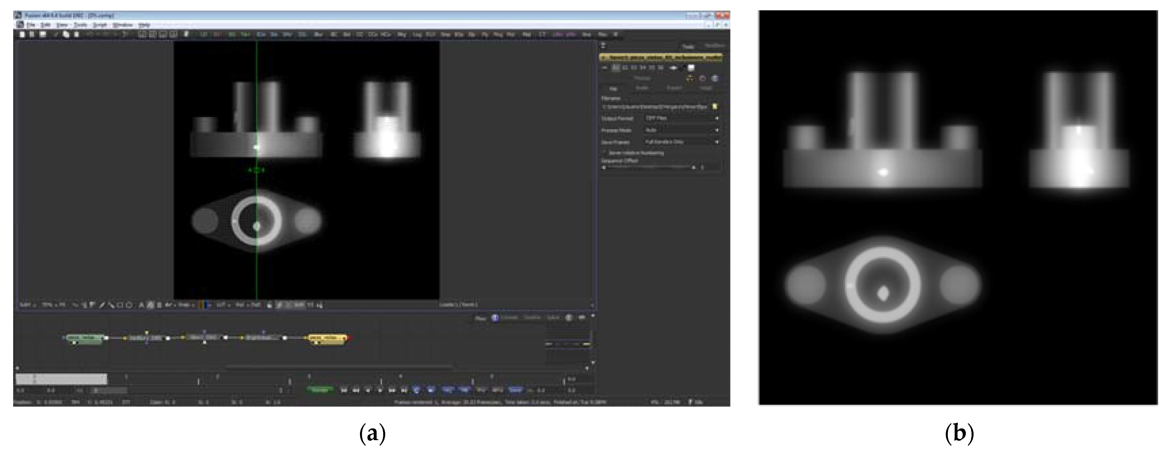
The second phase began by taking as a basis the 2D drawings generated in the first phase, creating from them images of the part to which depth gradients were applied, i.e., different shades of gray were used to represent the different thicknesses of the parts (simplified radiographs, Figure 1c and Figure 3c). To carry out this operation, the image modification program Adobe Photoshop® was used, which offers a multitude of options for manipulation and creation of gray gradients. These images were then processed using Blackmagic Design Fusion® (BDF, Figure 7a), used in digital compositing of video and film, which blurred the edges of the figures to obtain images similar to real radiographies (Figure 7b). As an alternative to BDF, The Foundry Nuke® could be used, which is a program widely used in film production. In spite of this, the authors chose BDF because to obtain similar results, the price is much lower and the working environment is more user-friendly.
The third phase was carried out by three-dimensionally modeling the part and its internal defects, using Autodesk 3DS Max®, which is a program that has advanced modeling, material application, and lighting options, and offers a student version that is free if used for non-commercial educational purposes. Alternatively, the authors believe that Blender®, which has many of the features of Autodesk 3DS Max® and is free of charge, could be used as an alternative. Once the 3D model was created, the IVP was developed (Figure 5), i.e., a computer application was generated that allows the user to interact with the different 3D models created in the previous phase (e.g., by rotating them or zooming in/out the point of view). To carry out this operation, Epic Unreal Engine 4® (UE4) was used, which is a free game engine (if not used for commercial purposes) that allows programming a multitude of functionalities without typing code, using a visual scripting system. The authors consider that Unity Technologies Unity® could be used as an alternative to UE4, since it has many of the features of UE4, both being widely used in the educational world [43,44].
It should be noted that the programs used to create the didactic material and the alternatives suggested by the authors have a large community of users who share experiences and knowledge on the Internet. This fact favors the existence of a large amount of updated and free information about the use of these programs and the resolution of possible problems that may arise during their use. However, there are several alternative programs to those described in this article that could be used in each of the three phases of creation of the methodology explained in this article.

6. Classroom Implementation

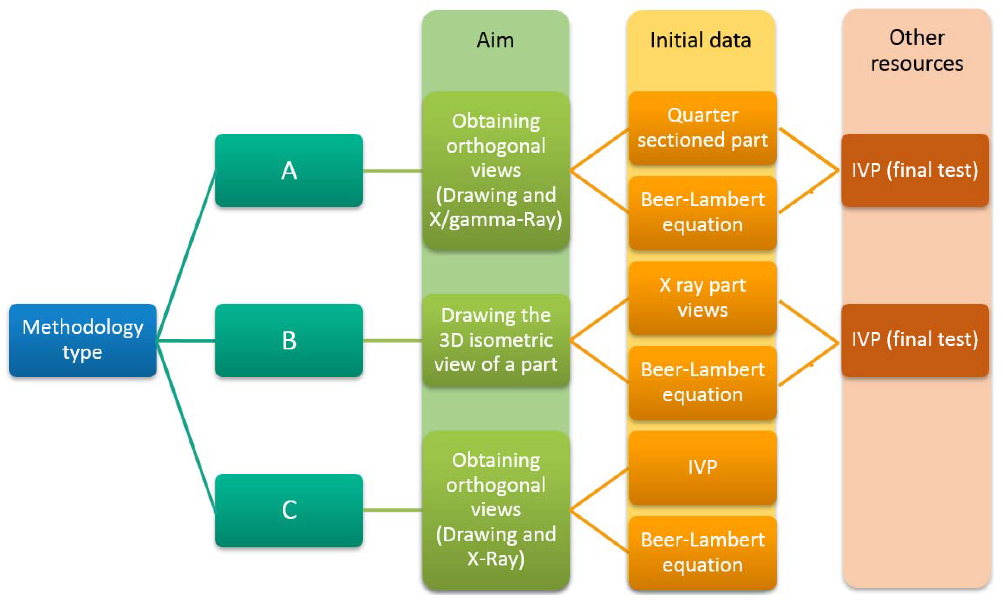
The classroom implementation of the methodology proposed in this work consists of two different stages: master class and problem solving. During the first stage the professor gives a one-hour master class explaining the theoretical background of industrial radiology and its application to the analysis of radiographed views of industrial parts, and using realistic-looking virtual radiographs (Figure 7b) to increase student motivation. During this stage, students are expected to understand the multidisciplinary link between TD and industrial radiology. After the master class, the second stage begins, which is dedicated to students solving different types of problems, such as those shown in Figure 8:
  • Methodology type A: students must obtain orthogonal views of the part quarter sectioned from both the points of view of TD and industrial radiology (i.e., from Figure 1a they must obtain Figure 1b,c; and from Figure 3a they must obtain Figure 3b,c).
  • Methodology type B: inversely to methodology type A, students must represent an isometric 3D view of the part based on the orthogonal views of the part (i.e., from Figure 1c, Figure 3c or Figure 6b they must obtain the whole part represented in Figure 1a or Figure 3a, respectively).
  • Methodology type C: students use the IVP by interacting with the 3D model of the part (Figure 5) to subsequently represent the orthogonal views of the part. Since the IVP allows interaction with the parts, the use of the IVP enables students to reinforce their spatial vision skills in a self-directed manner.
Each of the three methodologies described (Figure 8) allows the creation of exercises with different levels of difficulty, depending on: (i) the presence of internal defects inside the quarter sectioned part (lower difficulty if there are no internal defects and higher difficulty if there are); and (ii) the use of simplified or realistic-looking radiographic images (lower difficulty in the case of simplified images because they show the edges of the parts as well-defined, and higher difficulty in the case of realistic-looking images because they show the edges of the parts blurred).
The gray gradient shown in radiographic images is directly related to spatial visualization due to: (i) the gray coloration of radiographic views of a part depends on the thickness of each zone of the part, as follows from the Beer–Lambert equation; (ii) the thickness traversed by the radiation beam in each zone of the part depends on the orthogonal view used to obtain the radiography. Through the resolution of the exercises described in this work, the spatial understanding of the part and the localization of its internal defects are doubly reinforced. In fact, the student must understand the complex three-dimensional geometry of the part, and at the same time he or she must understand the gray gradient which in turn depends on the geometry of the part.
Through the exercises proposed in this work and according to the teaching experience of the authors applying this methodology, different abilities of the students are helped to improve, such as:
  • Mentally visualize complex three-dimensional geometries in space.
  • Recognize figures isolated from the context in which they are found.
  • Recognize that an object maintains its shape even if it is no longer visible in whole or in part.
  • Relate the position of a three-dimensional object with respect to an observer or other object used as a reference point.
  • Identify the relationships between different objects placed in space.
  • Compare different three-dimensional objects by visually analyzing their similarities and differences.
  • Recall and mentally recreate visual characteristics, as well as the position they occupied in space, of a set of objects.
The results of 25 sophomore students from a mechanical engineering degree, who used the methodology proposed in this article (Figure 8), solving various exercises with it, are shown in Table 1. Each student used each described methodology (A, B, and C) and the solved exercises were evaluated by a teacher. During the experience, several exercises were proposed to the students, who worked individually to spatially understand the different parts. Although cooperative work is interesting from a didactic point of view, individual resolution was planned to achieve the aim of the present study. Thus, it can be seen that methodology B (obtain 3D views from orthogonal views) was more complicated for the students than methodology A (obtain orthogonal views from 3D view). In addition, increasing the level of realism of the radiographs (2nd stage) was a more complicated challenge for the students. Similarly, including defects in the parts complicates spatial comprehension and, hence, makes it more difficult to solve the exercises. Finally, according to the results of Table 1, the use of an IVP platform, such as the one presented in this article (Figure 5), facilitates the student’s spatial understanding of the parts. Although there are studies establishing different spatial abilities as a function of gender [45], this aspect was not taken into account in the present small-scale study. Similarly, gender was excluded from the analysis in previous studies related to spatial understanding of radiographs [32] and, in other papers, the gender differences related to spatial skills were found to be non-relevant [46].

7. Described ICT-Based Didactic Tools and 2030 Agenda

The United Nations General Assembly Resolution 70/1, entitled “Transforming our world: the 2030 Agenda for Sustainable Development” (commonly known as 2030 Agenda or Agenda 2030) sets out 17 sustainable development goals (SDG), with 169 associated targets [47]. The ICT-based didactic tools described in this paper are useful means of contributing to the achievement of some of these SDG and their associated targets, in particular the ones given in Table 2.
The United Nations Educational, Scientific, and Cultural Organization (UNESCO) highlights the importance of the use of ICT in education, in particular, it indicates that “ICT can complement, enrich, and transform education for the better” and “[…] UNESCO guides international efforts to help countries understand the role such technology can play to accelerate progress toward Sustainable Development Goal 4” [48]. Furthermore, as pointed out in previous works, virtual educational tools make it possible to reduce or almost eliminate the costs associated with practical laboratory classes, since they make it possible to avoid the use of materials and machines traditionally needed to teach these classes [12]. Taking into account these facts and analyzing the description of the targets exposed in Table 1, it is possible to elucidate how the didactic tools presented in this work, as well as others of a similar nature, can contribute to achieving these targets. Indeed, the use of virtual radiographs and the IVP eliminates the need for educational centers to have real parts that must be radiographed by means of an X-ray or gamma-ray machine. This type of machine has a high cost both in economic terms (its purchase is a high outlay that many educational centers cannot afford) and in terms of the environmental impact associated with its manufacturing process.
The use of virtual radiographs and IVP can contribute to creating quality technical education that is affordable and accessible to more people (target 4.3), which would lead to a greater number of people with relevant skills who could take up decent jobs or foster entrepreneurship (targets 4.4 and 8.3), as well as promoting youth employment (targets 8.6 and 8.b). This is understandable, since the lower cost of quality technical education should result in a greater number of students accessing it [49] and, as a result, these people (especially youth) will become skilled workers with greater possibilities of getting quality jobs or creating businesses. Furthermore, since the need to use real radiology machines is eliminated, it is possible for more teachers to create the necessary educational tools to teach their subject, sharing knowledge, experiences, virtual tools and cooperating with teachers from other countries (target 4.c). In addition, replacing real radiographs and parts with their virtual equivalents implies that no X-ray or gamma-ray machines or consumables are needed to make real radiographs, a fact that contributes: (i) to a reduction in the production and consumption of goods (target 12.1), (ii) to the use of fewer natural resources (target 12.2), and (iii) to the generation of less waste (target 12.5).
At a worldwide level, there are currently a large number of educational centers that have computer equipment and Internet connection that would allow them to benefit from the use of didactic tools such as the one presented in this work. Unfortunately, these type of educational methodologies, based exclusively on ICT, are not yet usable in large regions of the world (most of them in developing countries [50], many of which are aimed at the SDG and associated targets shown in Table 2), where the income level is low and consequently this type of technology has little or no presence in educational centers.

8. Conclusions

This paper presents an original interdisciplinary learning (IL) methodology that allows engineering students to learn technical drawing (TD) and industrial radiology by creating an interdisciplinary link between both subjects. This methodology employs a set of orthogonal drawings of parts and images of virtual radiographs (simplified or realistic looking), and a computer application that allows the user to interact with these same parts virtually recreated in three dimensions. The IL methodology described is based on three types of exercises through which students can improve their spatial ability by facilitating their understanding about: (i) the position occupied by the internal defects of the different virtual parts; (ii) how the internal defects would look in radiographs taken in the direction of the orthogonal views commonly employed in TD; (iii) the different shades of gray seen in industrial radiographs and their relation to the Beer–Lambert equation; and (iv) the resolution of specific TD exercises. According to the results obtained in a small-scale study, the IL methodology described in this article is effective, as indicated by the fact that students obtain high qualifications (between 80% and 100%) when solving the proposed exercises. Furthermore, the results show that the exercises that students find most difficult to solve are those consisting of obtaining 3D isometric views from highly realistic radiographic images corresponding to parts with internal defects, while the exercises that obtain the highest scores are those corresponding to obtaining orthogonal views from the 3D model displayed in a computer application. Finally, it has been shown how the virtual teaching tools described in this work can contribute to achieving some of the sustainable development goals contained in the 2030 Agenda of the United Nations.
From the experience of using this methodology in recent years with mechanical engineering students, it has been shown that the spatial understanding of the defectology of parts shown in a radiograph is an aspect that requires training and that can have much educational content in common with TD. In this sense, the link between industrial radiology and TD has helped to enhance students’ interest in these subjects and has also helped them to appreciate practical applications of TD in the work of an engineer. In addition, the use of interactive virtual platforms helps students to improve their spatial comprehension of both the parts and the defects inside them. However, although the subjective experience of the authors, as well as the students’ own comments and the small-scale study performed, suggests that spatial ability improved in relation to the spatial understanding of parts with defects, a limitation of this work is the absence of a significant measurement of parameters that allow this aspect to be quantified.
Although this work focuses on exposing a teaching methodology focused on a particular case (TD and industrial radiology), the IL system proposed can be adapted to the multidisciplinary teaching of TD together with other subjects or concepts that require a high capacity of spatial understanding by the students, e.g., crystallography, ternary phase diagrams, constitution of mechanical machines or structures, etc.

Author Contributions

Conceptualization and methodology, D.V. and M.P.R.; software, D.V. and M.P.R.; validation, D.V., J.E. and M.L.; supervision, D.V., M.P.R., J.E. and M.L.; writing—original draft, D.V. and J.E.; writing—review & editing, D.V., M.P.R., J.E. and M.L. All authors have read and agreed to the published version of the manuscript.

Funding

This research received no external funding.

Conflicts of Interest

The authors declare no conflict of interest.

References

  1. Sierra, E.; Garmendia, M.; Barrenetxea, L. Solving the Problem of Interpreting Views: Teaching the Part Visualization Process. Int. J. Eng. Educ. 2012, 28, 663–673. [Google Scholar]
  2. Makgato, M.; Khoza, S.D. Difficulties of student teachers in the engineering Graphics and Design course at a South African university: Snapshot on sectional drawing. Eurasia J. Math. Sci. Technol. Educ. 2016, 12, 703–715. [Google Scholar] [CrossRef]
  3. Vergara, D.; Rubio, M.P. Active methodologies through interdisciplinary teaching links: Industrial radiography and technical drawing. J. Mater. Educ. 2012, 34, 175–185. [Google Scholar]
  4. Contreras, M.J.; Escrig, R.; Prieto, G.; Elosua, M.R. Spatial visualization ability improves with and without studying technical drawing. Cogn. Process. 2018, 19, 387–397. [Google Scholar] [CrossRef]
  5. Mendez, M.; Martin, S.; Arias, N.; Rubio, R.; Arias, J.L. Assessment of visual and memory components of spatial ability in engineering students who have studied technical drawing. Int. J. Eng. Educ. 2014, 30, 806–812. [Google Scholar]
  6. Ogunkola, B.; Knight, C. Does technical drawing increase students’ mental rotation ability? Cogent Educ. 2018, 5, 1–9. [Google Scholar] [CrossRef]
  7. Ogunkola, B.; Knight, C. Technical drawing course, video games, gender, and type of school on spatial ability. J. Educ. Res. 2019, 112, 575–589. [Google Scholar] [CrossRef]
  8. Levy, D. How Dynamic Visualization Technology can Support Molecular Reasoning. J. Sci. Educ. Technol. 2013, 22, 702–717. [Google Scholar] [CrossRef]
  9. Fogarty, J.; McCormick, J.; El-Tawil, S. Improving student understanding of complex spatial arrangements with virtual reality. J. Prof. Issues Eng. Educ. Pract. 2018, 144, 04017013. [Google Scholar] [CrossRef]
  10. Jamil, Z.; Saeed, A.A.; Madhani, S.; Baig, S.; Cheema, Z.; Fatima, S.S. Three-dimensional visualization software assists learning in students with diverse spatial intelligence in medical education. Anat. Sci. Educ. 2019, 12, 550–560. [Google Scholar] [CrossRef]
  11. Pei, X.; Jin, Y.; Zheng, T.; Zhao, J. Longitudinal effect of a technology-enhanced learning environment on sixth-grade students’ science learning: The role of reflection. Int. J. Sci. Educ. 2020, 42, 271–289. [Google Scholar] [CrossRef]
  12. Vergara, D.; Extremera, J.; Rubio, M.P.; Dávila, L.P. Meaningful learning through virtual reality learning environments: A case study in materials engineering. Appl. Sci. 2019, 9, 4625. [Google Scholar] [CrossRef] [Green Version]
  13. Extremera, J.; Vergara, D.; Rubio, M.P.; Dávila, L.P.; de la Prieta, F. Effects of time in virtual reality learning environments linked with materials science and engineering. In Advances in Intelligent Systems and Computing, Proceedings of the Methodologies and Intelligent Systems for Technology Enhanced Learning, 10th International Conference MIS4TEL 2020, L’Aquila, Italy, 17–19 June 2020; Vittorini, P., Di Mascio, T., Tarantino, L., Temperini, M., Gennari, R., de la Prieta, F., Eds.; Springer: Cham, Switzerland, 2020; Volume 1241. [Google Scholar]
  14. Chen, Y.C.; Chi, H.L.; Hung, W.H.; Kang, S.C. Use of tangible and augmented reality models in engineering graphics courses. J. Prof. Issues Eng. Educ. Pract. 2011, 137, 267–276. [Google Scholar] [CrossRef]
  15. Vergara, D.; Rubio, M.P.; Lorenzo, M. A virtual environment for enhancing the understanding of ternary phase diagrams. J. Mater. Educ. 2015, 37, 93–101. [Google Scholar]
  16. Vergara, D.; Rubio, M.P.; Lorenzo, M. A virtual resource for enhancing the spatial comprehension of crystal lattices. Educ. Sci. 2018, 8, 153. [Google Scholar] [CrossRef] [Green Version]
  17. Extremera, J.; Vergara, D.; Dávila, L.P.; Rubio, M.P. Virtual and augmented reality environments to learn the fundamentals of crystallography. Crystals 2020, 10, 456. [Google Scholar] [CrossRef]
  18. Melgosa, C.; Ramos, B.; Roman, A. Spatial visualization learning in engineering: Traditional methods vs. a web-based tool. Educ. Technol. Soc. 2014, 17, 142–157. [Google Scholar]
  19. Vergara, D.; Rubio, M.P.; Lorenzo, M. On the use of PDF-3D to overcome spatial visualization difficulties linked with ternary phase diagrams. Educ. Sci. 2019, 9, 67. [Google Scholar] [CrossRef] [Green Version]
  20. Murad, S.; Passero, I.; Francese, R.; Tortora, G. An empirical evaluation of technical drawing didactic in virtual worlds. Int. J. Online Eng. 2011, 7, 23–30. [Google Scholar] [CrossRef] [Green Version]
  21. Pando, P.; Suárez, J.M.; Busto, B.; Rodríguez, D.; Álvarez, P.I. Can interactive web-based CAD tools improve the learning of engineering drawing? A case study. J. Sci. Educ. Technol. 2014, 23, 398–411. [Google Scholar] [CrossRef]
  22. Baronio, G.; Motyl, B.; Paderno, D. Technical Drawing Learning Tool-Level 2: An interactive self-learning tool for teaching manufacturing dimensioning. Comput. Appl. Eng. Educ. 2016, 24, 519–528. [Google Scholar] [CrossRef]
  23. Speranza, D.; Baronio, G.; Motyl, B.; Filippi, S.; Villa, V. Best practices in teaching technical drawing: Experiences of collaboration in three Italian universities. In Lecture Notes in Mechanical Engineering, Advances on Mechanics, International Joint Conference on Mechanics, Design Engineering and Advanced Manufacturing JCM 2017; Eynard, B., Nigrelli, V., Oliveri, S., Peris-Fajarnes, G., Rizzuti, S., Eds.; Springer: Cham, Switzerland, 2016; pp. 905–914. [Google Scholar]
  24. Mansilla, V.B.; Duraising, E.D. Targeted assessment of students’ interdisciplinary work: An empirically grounded framework proposed. J. High. Educ. 2007, 78, 215–237. [Google Scholar] [CrossRef]
  25. Spelt, E.J.H.; Biemans, H.J.A.; Tobi, H.; Luning, P.A.; Mulder, M. Teaching and learning in interdisciplinary higher education: A systematic review. Educ. Psychol. Rev. 2009, 21, 365–378. [Google Scholar] [CrossRef] [Green Version]
  26. Van Merriënboer, J.J.G. Training Complex Cognitive Skills: A Four-Component Instructional Design Model for Technical Training; Educational Technology: Englewood Cliffs, NJ, USA, 1997. [Google Scholar]
  27. White, D.; Delaney, S. Full STEAM ahead, but who has the map for integration?—A PRISMA systematic review on the incorporation of interdisciplinary learning into schools. Lumat 2021, 9, 9–32. [Google Scholar] [CrossRef]
  28. Borrego, M.E.; Rhyne, R.; Hansbarger, L.C.; Geller, Z.; Edwards, P.; Griffin, B.; McClain, L.; Scaletti, J. V Pharmacy student participation in rural interdisciplinary education using problem based learning (PBL) case tutorials. Am. J. Pharm. Educ. 2000, 64, 355–363. [Google Scholar]
  29. Harrison, G.P.; Macpherson, D.E.; Williams, D.A. Promoting interdisciplinarity in engineering teaching. Eur. J. Eng. Educ. 2007, 32, 285–293. [Google Scholar] [CrossRef] [Green Version]
  30. Furlan, P.Y.; Kitson, H.; Andes, C. Chemistry, poetry, and artistic illustration: An interdisciplinary approach to teaching and promoting chemistry. J. Chem. Educ. 2007, 84, 1625–1630. [Google Scholar] [CrossRef]
  31. Mhamed, I.B.; Abid, S.; Fnaiech, F. Weld defect detection using a modified anisotropic diffusion model. J. Adv. Signal. Process. 2012, 2012, 46. [Google Scholar] [CrossRef] [Green Version]
  32. Nilsson, T.; Hedman, L.; Ahlqvist, J. Visual-spatial ability and interpretation of three-dimensional information in radiographs. Dentomaxillofac. Radiol. 2007, 36, 86–91. [Google Scholar] [CrossRef]
  33. Ramírez-Arias, J.L.; Rodriguez-Treviño, C.; González-Vergara, C. The challenge of radiology education in developing countries. Biomed. Imaging Interv. J. 2008, 4, e2. [Google Scholar] [CrossRef] [PubMed] [Green Version]
  34. Scarsbrook, A.F.; Graham, R.N.J.; Perriss, R.W. Radiology education: A glimpse into the future. Clin. Radiol. 2006, 61, 640–648. [Google Scholar] [CrossRef] [PubMed]
  35. Felisberto, M.K.; Centeno, T.M.; Arruda, L.V.R.; Lopes, H.S. Automatic analysis of radiographic images for non destructive test applications. In Proceedings of the 10th SEM International Congress on Experimental and Applied Mechanics, Costa Mesa, CA, USA, 7–10 June 2004. [Google Scholar]
  36. Nacereddine, N.; Zelmat, M.; Belaïfa, S.S.; Tridi, M. Weld defect detection in industrial radiography based digital image processing. In Proceedings of the Conference of the World Academy of Science Engineering and Technology, Berlin, Germany, 19–21 January 2005; Ardil, C., Ed.; World Academy of Science, Engineering and Technology: Canakkale, Turkey, 2005; Volume 2, pp. 112–115. [Google Scholar]
  37. Nacereddine, N.; Tridi, M. Computer-aided shape analysis and classification of weld defects in industrial radiography based invariant attributes and neural networks. In Proceedings of the 4th International Symposium on Image and Signal Processing and Analysis (ISPA 2005), Zagreb, Croatia, 15–17 September 2005; Loncaric, S., Babic, H., Bellanger, M., Eds.; IEEE: New York, NY, USA, 2005; pp. 88–93. [Google Scholar]
  38. Rodríguez-Martín, M.; Rodríguez-Gonzálvez, P. Learning methodology based on weld virtual models in the mechanical engineering classroom. Comput. Appl. Eng. Educ. 2019, 27, 1113–1125. [Google Scholar] [CrossRef]
  39. Rodríguez-Martín, M.; Rodríguez-Gonzálvez, P. 3D Learning materials from reverse engineering for weld inspection training. Dyna 2019, 94, 238–239. [Google Scholar] [CrossRef]
  40. Forsyth, D.S. Nondestructive testing of corrosion in the aerospace industry. In Corrosion Control in the Aerospace Industry; Benavides, S., Ed.; Woodhead Publishing: Cambridge, UK, 2009; pp. 111–130. [Google Scholar]
  41. Khorshidi, A.; Khosrowpour, B.; Hosseini, S.H. Determination of defect depth in industrial radiography imaging using MCNP code and SuperMC software. Nucl. Eng. Technol. 2020, 52, 1597–1601. [Google Scholar] [CrossRef]
  42. Economides, S.; Tritakis, P.; Papadomarkaki, E.; Carinou, E.; Hourdakis, C.; Kamenopoulou, V.; Dimitriou, P. Occupational exposure in Greek industrial radiography laboratories (1996–2003). Radiat. Prot. Dosim. 2006, 118, 260–264. [Google Scholar] [CrossRef] [PubMed]
  43. Vergara, D.; Rubio, M.P.; Lorenzo, M. On the design of virtual reality learning environments in engineering. Multimodal Technol. Interact. 2017, 1, 11. [Google Scholar] [CrossRef] [Green Version]
  44. Vergara, D.; Extremera, J.; Rubio Cavero, M.P.; Dávila, L.P. The technological obsolescence of virtual reality learning environments. Appl. Sci. 2020, 10, 915. [Google Scholar] [CrossRef] [Green Version]
  45. Peters, M.; Chisolm, P.; Laeng, B. Spatial ability, student gender, and academic performance. J. Eng. Educ. 1995, 84, 69–73. [Google Scholar] [CrossRef]
  46. Molina-Carmona, R.; Pertegal-Felices, M.L.; Jimeno-Morenilla, A.; Mora-Mora, H. virtual reality learning activities for multimedia students to enhance spatial ability. Sustainability 2018, 10, 1074. [Google Scholar] [CrossRef] [Green Version]
  47. United Nations, Department of Economic and Social Affairs, Sustainable Development. Available online: https://sdgs.un.org/ (accessed on 10 April 2021).
  48. United Nations Educational, Scientific and Cultural Organization. Available online: https://en.unesco.org/themes/ict-education (accessed on 10 May 2021).
  49. Vergara, D.; Rubio, M.P.; Lorenzo, M. New approach for the teaching of concrete compression tests in large groups of engineering students. J. Prof. Issues Eng. Educ. Pract. 2017, 143, 05016009. [Google Scholar] [CrossRef]
  50. Kim, B.; Park, M.J. Effect of personal factors to use ICTs on e-learning adoption: Comparison between learner and instructor in developing countries. Inf. Technol. Dev. 2018, 24, 706–732. [Google Scholar] [CrossRef]
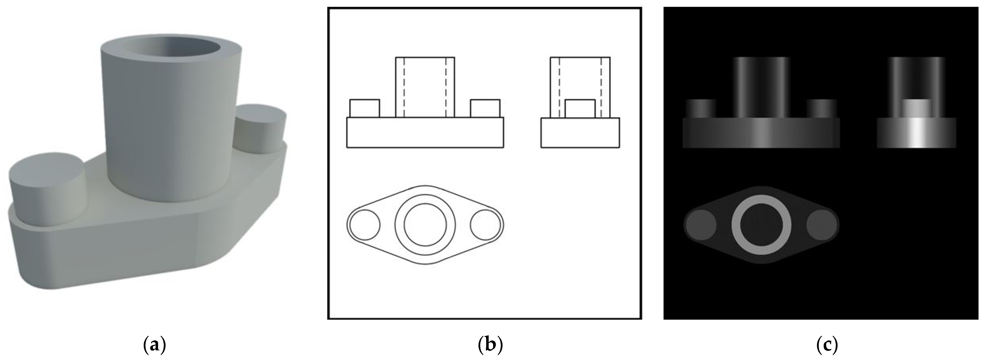
Figure 1. Relationship between TD and industrial radiology: (a) 3D view of the virtual part; (b) orthogonal views of the virtual part drawn according to TD norms; (c) orthogonal views of the virtual part represented as a simplified radiograph (with well-defined edges).
Applsci 11 05634 g001
Figure 2. Graphical justification of the gray gradient of the part cylinders.
Applsci 11 05634 g002
Figure 3. Relationship between TD and industrial radiology: (a) 3D view of the virtual part with internal defects (quarter sectioned); (b) orthogonal views of the virtual part, drawn according to TD norms, where internal defects are drawn in a dashed line; (c) orthogonal views of the virtual part represented as a radiograph (simplified, with well-defined edges) where internal defects are colored in light gray.
Applsci 11 05634 g003
Figure 4. Real X-ray radiography of a metallic weld with defects (lack of fusion and vermicular pores).
Applsci 11 05634 g004
Figure 5. IVP to allow students to freely explore the parts and their internal defects: (a) opaque view; (b) translucid view, where inner inclusions are shown.
Applsci 11 05634 g005
Figure 6. Methodology used for the creation of the didactic material.
Applsci 11 05634 g006
Figure 7. Image simulating a real radiograph: (a) manipulation of an image by means of BDF to obtain an image similar to a real radiograph; (b) realistic-looking radiographic image.
Applsci 11 05634 g007
Figure 8. Diagram showing the proposed exercises described in this work.
Applsci 11 05634 g008
Table 1. Obtained results applying the proposed methodologies.
Methodology 1Students without Errors in the Resolution (%)Remarks
AA196%Errors in the spatial visualization of parts
A292%Errors in the spatial visualization of parts
Defect spatial positioning errors
BB11st stage92%Difficulty in spatial comprehension of the complete part
2nd stage84%Difficulty in spatial comprehension of the complete part
Defect spatial positioning errors
B21st stage88%Difficulty in spatial comprehension of the complete part
2nd stage80%Difficulty in spatial comprehension of the complete part
Defect spatial positioning errors
Students need more time to solve the exercises
C100%Students emphasize the usefulness of the IVP to improve spatial comprehension of the parts
1 A1 and B1: without defects; A2 and B2: with defects; 1st stage: low realism (Photoshop®); 2nd stage: high realism (BDF).
Table 2. SDG and associated targets that can be furthered through the use of the described ICT-based didactic tools.
SDGAssociated Targets
SDG 4
Ensure inclusive and equitable quality education and promote lifelong learning opportunities for all.
Target 4.3
Ensure equal access for all women and men to affordable and quality technical, vocational and tertiary education, including university.
Target 4.4
Substantially increase the number of youth and adults who have relevant skills, including technical and vocational skills, for employment, decent jobs and entrepreneurship.
Target 4.c
Substantially increase the supply of qualified teachers, including through international cooperation for teacher training in developing countries, especially least developed countries and small island developing States.
SDG 8
Promote sustained, inclusive and sustainable economic growth, full and productive employment and decent work for all.
Target 8.3
Promote development-oriented policies that support productive activities, decent job creation, entrepreneurship, creativity and innovation, and encourage the formalization and growth of micro-, small- and medium-sized enterprises, including through access to financial services.
Target 8.6
Substantially reduce the proportion of youth not in employment, education or training.
Target 8.b
Develop and operationalize a global strategy for youth employment and implement the Global Jobs Pact of the International Labour Organization.
SDG 12
Ensure sustainable consumption and production patterns.
Target 12.1
Implement the 10-year framework of programmes on sustainable consumption and production, all countries taking action, with developed countries taking the lead, taking into account the development and capabilities of developing countries.
Target 12.2
Achieve the sustainable management and efficient use of natural resources.
Target 12.5
Substantially reduce waste generation through prevention, reduction, recycling and reuse.
Publisher’s Note: MDPI stays neutral with regard to jurisdictional claims in published maps and institutional affiliations.