Article

Comprehensive Analysis of the Microstructure and Mechanical Properties of Friction-Stir-Welded Low-Carbon High-Strength Steels with Tensile Strengths Ranging from 590 MPa to 1.5 GPa

1
Department of Mechanical and Materials Engineering, Portland State University, Portland, OR 97201, USA
2
Department of Materials Science and Engineering, Inha University, Incheon 22212, Korea
3
Joining R&D Group, Korea Institute of Industrial Technology, Incheon 21999, Korea
*
Authors to whom correspondence should be addressed.
Appl. Sci. 2021, 11(12), 5728; https://doi.org/10.3390/app11125728
Submission received: 3 May 2021 / Revised: 15 June 2021 / Accepted: 17 June 2021 / Published: 21 June 2021

Abstract

:
High-strength steels are being increasingly employed in the automotive industry, requiring efficient welding processes. This study analyzed the materials and mechanical properties of high-strength automotive steels with strengths ranging from 590 MPa to 1500 MPa, subjected to friction stir welding (FSW), which is a solid-phase welding process. The high-strength steels were hardened by a high fraction of martensite, and the welds were composed of a recrystallized zone (RZ), a partially recrystallized zone (PRZ), a tempered zone (TZ), and an unaffected base metal (BM). The RZ exhibited a higher hardness than the BM and was fully martensitic when the BM strength was 980 MPa or higher. When the BM strength was 780 MPa or higher, the PRZ and TZ softened owing to tempered martensitic formation and were the fracture locations in the tensile test, whereas BM fracture occurred in the tensile test of the 590 MPa steel weld. The joint strength, determined by the hardness and width of the softened zone, increased and then saturated with an increase in the BM strength. From the results, we can conclude that the thermal history and size of the PRZ and TZ should be controlled to enhance the joint strength of automotive steels.

1. Introduction

Friction stir welding (FSW) is a well-known solid-state welding process with minimum thermal effect on weldments. FSW was initially applied to nonferrous metals and later to high-strength steels. Thomas et al. reported the feasibility of FSW for Cr and mild steels in 1999 [1]. Compared with the FSW of Al alloys, higher-strength tools are required to mitigate tool wear in the FSW of steel. Polycrystalline cubic boron nitride, W-based materials, and Si3N4 have been proposed as tool materials instead of steel used for the FSW of Al alloys [2]. Another important feature of friction stir-welded steels is the welding system deflection due to the high applied load. The system deflection interferes with the exact plunging of the welding tool. Accurate depth control has been successfully achieved in the FSW of steels using high-stiffness welding systems [3,4] and compensation methods such as offset control, constant force control [5,6], and force-deflection models [7,8]. Hybrid processes using an additional heat source can help reduce the yield strength of base materials and enhance the process capability [9,10,11,12].
As mild steel is being gradually replaced by high-strength steel in the automotive industry, studies have been conducted on the FSW of various high-strength steels. Cui et al. introduced FSW for a high-carbon steel (S70C) under various welding conditions. When the peak temperature was under the austenization temperature (A1), refined microstructure containing fine ferrite was observed, and when the peak temperature was higher than A1 temperature, martensite was found [13]. Sakar et al. evaluated the friction stir spot welding of DP590 steel sheets. The weldment has a stronger microstructure than the base metal due to phase transformation and dynamic recrystallization, and the larger the heat input, the larger the weld nugget is formed [14]. Santella et al. investigated the friction stir weldability of 780 MPa strength steels and boron steel. The 780 MPa steels, DP780 and TRIP780, showed hardening in the welds, while the boron steel showed softening in the heat affected zone (HAZ) [15]. Lee et al. reported the metallurgical characteristics of friction-stir-welded DP980 joints and the local tensile deformation characteristics during tensile tests using the digital image correlation (DIC) method. Unlike the DP780 steel welds [15], DP980 steel welds has a softened white band on the HAZ [16]. Hovanski et al. applied FSW to a 1.5 GPa-strength hot-stamped boron steel, one of the highest grades of automotive steel sheets, and reported that the welds had narrow ferrite band along the interface and prominent tempered martensite in the HAZ [17]. They devised a friction stir scribe welding scheme for Al/Fe lap joints using a special FSW tool [18]. Kang et al. reported the behavior of a Fe–Al–Si intermetallic layer and material flow at the FSW interface of the Al alloy and Al–Si-coated boron steel. The Al–Si coating on the boron steel could influence the interface formation and the mechanical behavior of the friction stir welds [19].
Despite the extensive studies on the FSW of various grades of high-strength steels, most studies have been conducted on a specific type of steel; it is necessary to comprehensively understand the FSW characteristics of steels of various grades. Matsushita et al. evaluated the FSW weldments of high-strength steel sheets with strengths between 590 MPa and 1180 MPa, and provided the microstructure, tensile test results, and hardness profiles, but only under a few welding conditions [20]. In this study, FSW was carried out on an automotive high-strength steel with strengths ranging from 590 MPa to 1500 MPa under the same welding conditions, and the metallurgical and mechanical characteristics in terms of the location of weld zones were clarified for each grade of steel.

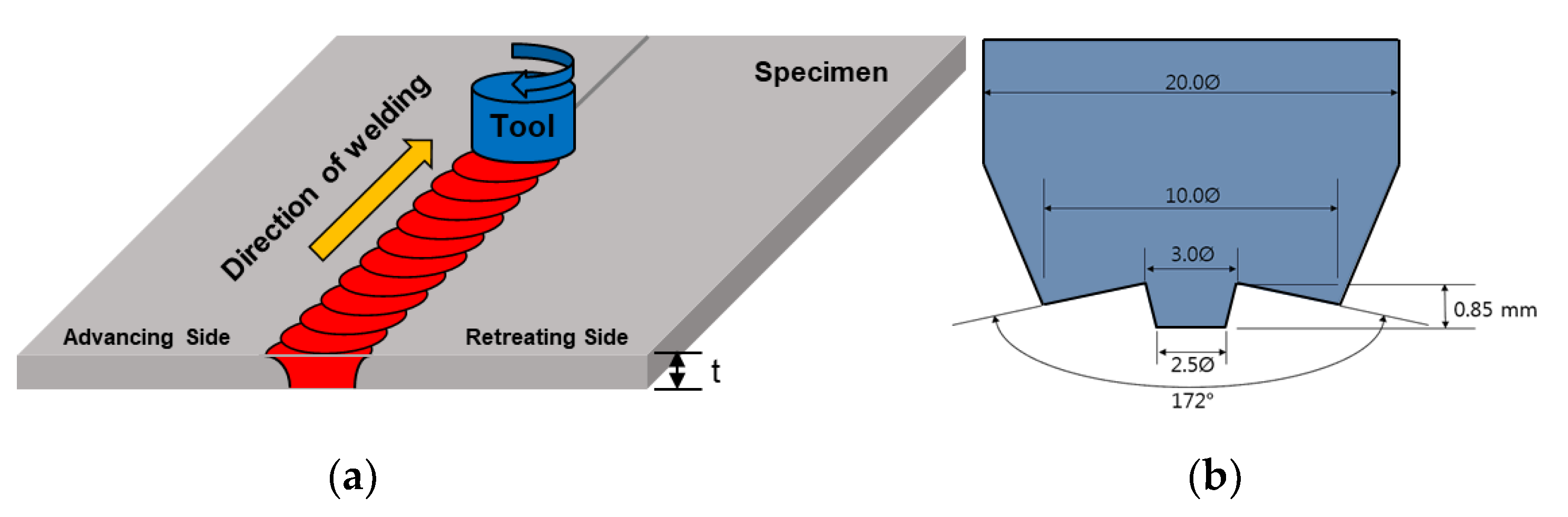
2. Experimental Setup

In this study, FSW was performed on high-strength steel sheets with a tensile strength range of 590–1500 MPa. Table 1 lists the chemical compositions of the applied materials. All the sheets were 1.0 mm thick, except for the 1.2 mm-thick (TRIP: transformation induced plasticity) 1180 steel and hot press forming (HPF) 1500 steel. HPF1500 steel sheets have a strength of 1535 MPa and a hardness of approximately 500 Hv after heat treatment, which involves heating the sheets in a furnace at a temperature of 950 °C for 6 min and then cooling them down in a quenching die through which cooling water at a temperature of 25 °C is circulated [21].
Figure 1a shows a schematic of the FSW process, where a position control welding machine (WX-FSW-03, WINZEN, Korea) is used. The tool was made of WC–Co12% with a concave-shaped shoulder and a conical frustum-shaped probe (Figure 1b). The tool was tilted by 2° in the welding direction, which is called the push or forehand angle in welding. Table 2 lists the detailed FSW conditions. When welding steel with a position control welding system, the tool cannot reach the specified position because of the heavy loads and resultant deflections of the system; therefore, an additional compensation was applied to the command value of the plunging depth to achieve full penetration for each specimen [7,8].
After FSW, the specimens were cut to a width of 25 mm, and the top and bottom surfaces were machined flat in accordance with the ISO 4136 standard. The tensile test was conducted at a head speed of 3 mm/min using a universal testing machine (AG-300 kNX plus, Shimadzu, Kyoto, Japan). The local deformation behavior of the specimen was recorded during the tensile test using the DIC technique (ARAMIS 3D, GOM GmbH, Germany). During the strain measurement, a trigger signal was sent to the camera every second. The transverse cross-section of weldment was polished and etched with 3% Nital solution (3 mL HNO3 and 100 mL ethanol), and the microstructure was observed using optical microscopy (OM) and scanning electron microscopy (SEM). The Vickers hardness was measured along the central line in the transverse section with an interval of 0.2 mm under a dwell time of 10 s and a load of 1.96 N using a microVickers hardness tester (FM-7E, Future Tech, Kawasaki, Japan).

3. Results and Discussion

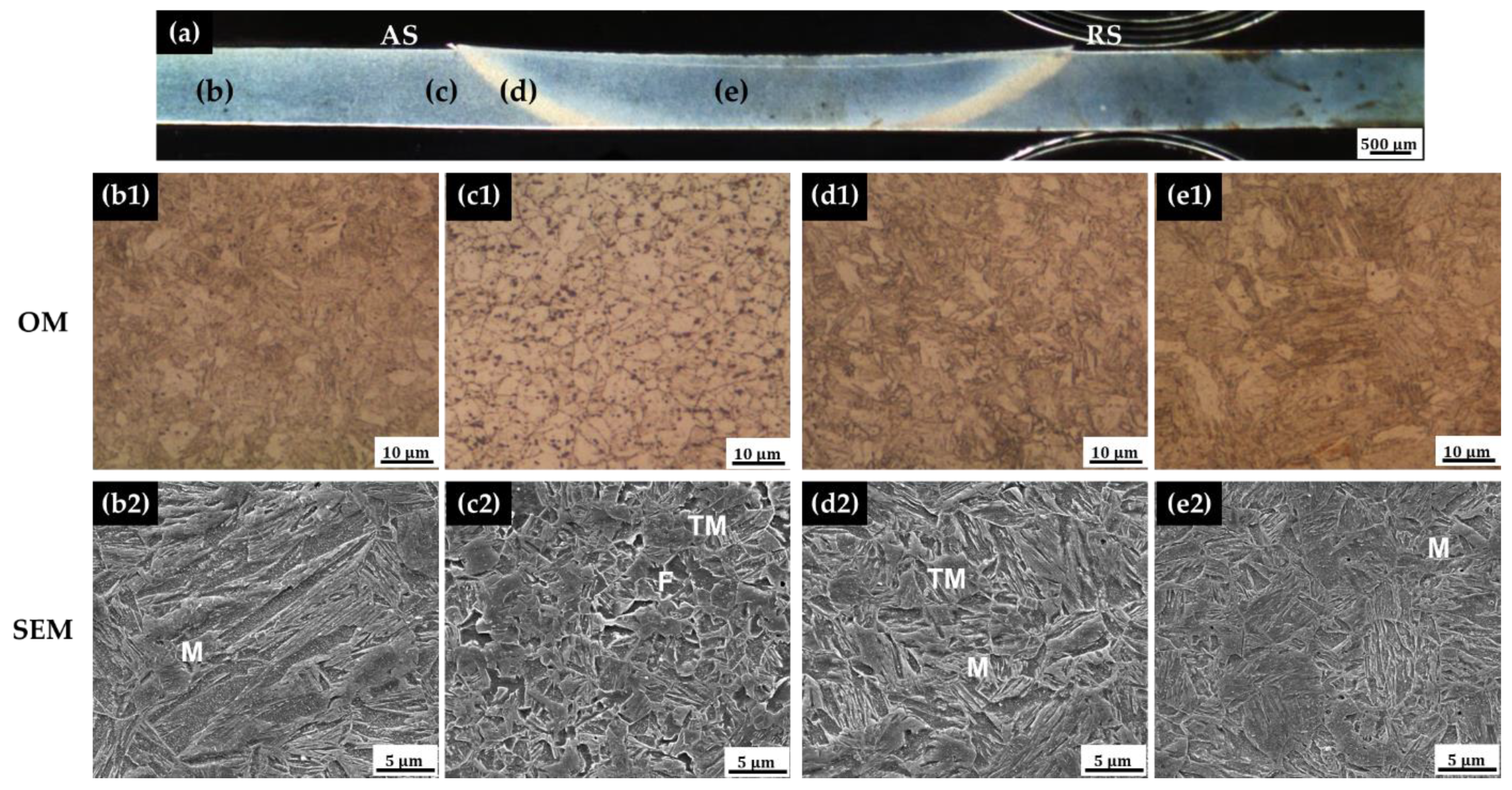
3.1. DP590, 780, and 980 Steels

The weld cross-section of the steel FSW exhibited a heterogeneous microstructure. In this study, austenization phase transformation occurred in the welds because the peak temperature was higher than the Ac3 temperature under all conditions. The Ac1 temperature represents the temperature at which pearlite begins to austenite during heating and the Ac3 temperature represents the temperature at which free ferrite is completely transformed into austenite during heating. The welds can be classified into four regions: (1) recrystallized zone (RZ), which comprises a stir zone and a heat-affected zone where the peak temperature is higher than the Ac3 temperature. The entire region was fully austenized when the temperature rose and then recrystallized because of phase transformation when cooled; (2) partial recrystallized zone (PRZ): the peak temperature is between Ac1 and Ac3; hence, the region cooled down after partial austenization at the peak temperature; (3) tempered zone (TZ): Since the peak temperature is lower than Ac1, the initial microstructure is not transformed to austenite, and only grain growth and tempered martensite could be observed because of the tempering effect; and (4) base metal (BM): the initial microstructure is maintained. Each zone was identified using the microstructure, and also the peak temperature was estimated.
The average hardness values of the DP590, DP780, and DP980 steels in the RZ were 310, 332, and 494 Hv, respectively, which were significantly higher than those in the other zones (Figure 2). The average hardness values of the BM of DP590, DP780, and DP980 steels were 227, 294, and 330 Hv, respectively, and the hardness increase in the RZ relative to the BM was approximately 37% for DP590, 13% for DP780, and 50% for DP980. The hardness increase in the RZ is relatively high in the DP980 steel compared with the other DP steels. This is because the DP980 steel has high hardenability owing to its relatively high carbon content compared with the other DP steels, as seen from the chemical compositions listed in Table 1. Unlike DP590, the DP780 and DP980 steels underwent softening in the PRZ and TZ, and the minimum hardness values in these zones were 265 Hv and 257 Hv, respectively, which are lower than the BM hardness. Slight softening occurred in the DP780 steel, whereas severe softening occurred in the DP980 steel. The softening of DP980 steel results from tempered martensite, and the high-volume fraction of martensite in the BM caused severe softening in the PRZ and TZ.
Figure 3 shows the weld cross-section of the DP590 steel welds by zone. The microstructure of the BM of the DP590 steel comprises a ferrite matrix and martensite islands along the matrix boundary (Figure 3b). In the RZ, as shown in Figure 3e, the ferrite grain size decreased, and the martensite fraction increased. As a result, the hardness of the RZ is higher than that of the BM. Because the PRZ has a peak temperature between Ac1 and Ac3, the initial microstructure is partially transformed into austenite during heating, and when cooled, fine ferrite grains and martensite are formed in the region where partial transformation occurred previously (Figure 3d). The PRZ has a lower volume fraction of martensite than the RZ because only partial austenization occurred, and its cooling rate was lower than that in the RZ. Therefore, it exhibited a lower hardness than the RZ (Figure 2). In the TZ, the peak temperature was slightly below Ac1, resulting in the formation of tempered martensite (Figure 3c).
Figure 4 shows the weld cross-section of the DP780 steel welds by zone. The microstructure of the DP780 BM has a finer grain size of the ferrite matrix and a higher volume fraction of martensite compared with that of the DP590 steel (Figure 4b). The RZ is rapidly cooled after heating above the Ac3 temperature, causing martensitic transformation, increasing the martensitic volume fraction, and making it harder than the BM (Figure 4e). Because the PRZ has a peak temperature between Ac1 and Ac3, it partially transforms to austenite during heating. Subsequently, during cooling, bainite, martensite, and a polygonal ferrite structure were formed (Figure 4d). In the TZ, the peak temperature was lower than Ac1; hence, a tempering effect can be observed, resulting in grain growth and tempered martensitic formation (Figure 4c).
Figure 5 shows the weld cross-section of the DP980 steel welds by zone. Compared with the previously observed DP590 and DP780 steel sheets, the microstructure of the DP980 steel has a finer grain size of the matrix ferrite, a larger volume fraction of martensite, and a higher carbon content, resulting in a relatively higher hardness than BM (Figure 5b). The RZ microstructure has a fully martensitic structure after being heated above Ac3 and rapidly cooled for martensitic transformation (Figure 5e). In the PRZ, as shown in Figure 5d, the peak temperature is between Ac1 and Ac3, and only partial phase transformation occurs, but most of the observation region is austenized and recrystallized as a martensitic structure during cooling. In the TZ, since the peak temperature is lower than Ac1 and because of the local tempering of the metastable martensite, the hardness decreases (Figure 5c).

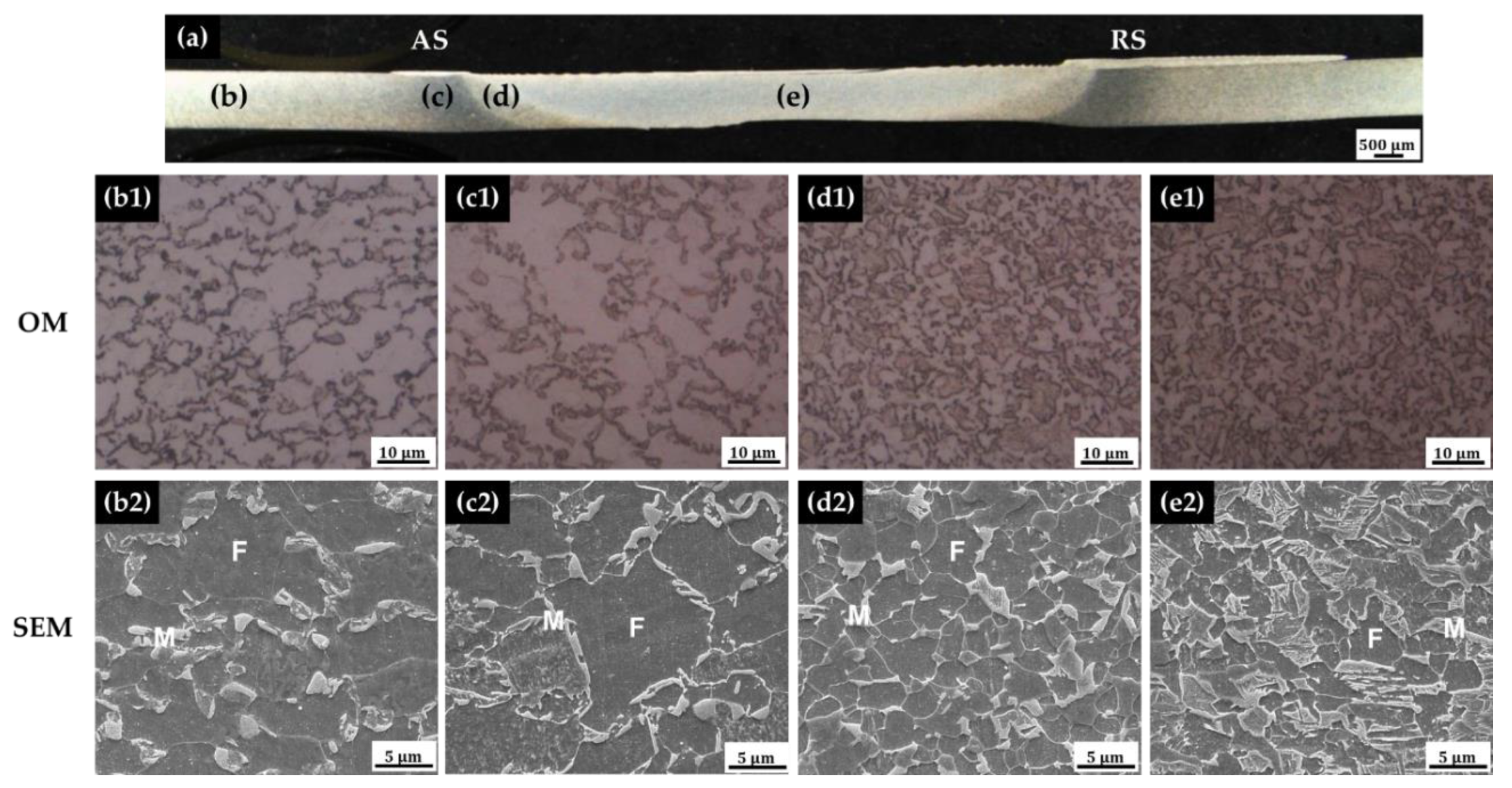
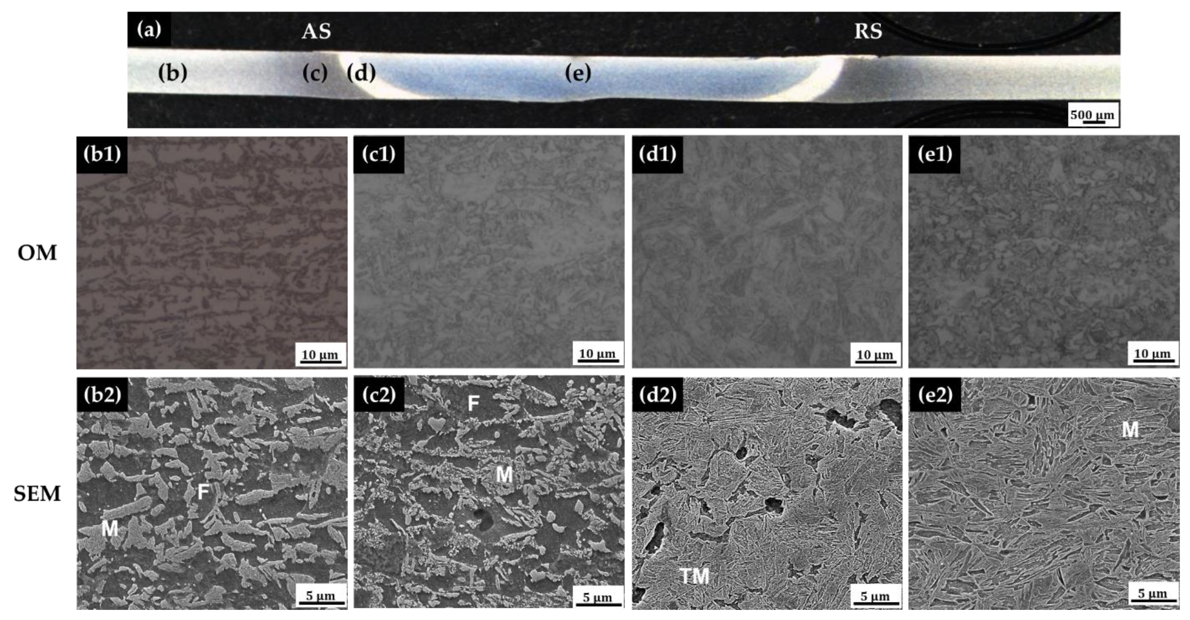
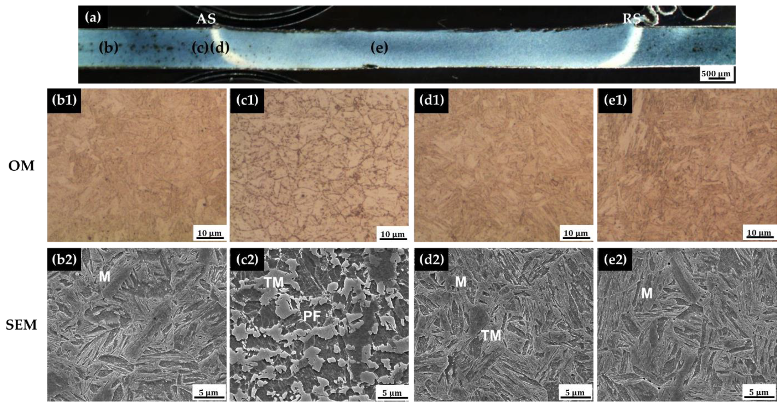
3.2. TRIP1180, MS1300, and HPF1500 Steels

Figure 6 shows the weldment hardness distributions for the TRIP1180, MS1300, and HPF1500 steels. The average hardness values of the TRIP1180, MS1300, and HPF1500 steel BM were 348, 447, and 500 Hv, respectively, and the average hardness values of the RZ were 475, 430, and 500 Hv, respectively. MS1300 steel has a lower hardness in the RZ than the TRIP1180 and HPF1500 steels, which can be attributed to the lower hardenability. The carbon equivalent (Ceq) for MS1300 is 0.27 wt%, whereas the Ceq values for the TRIP1180 and HPF1500 steels are 0.32 wt% and 0.31 wt%, respectively, when using Ceq (=C + Si/50 + Mn/25 + P/2 + Cr/25 + 14B) for high-strength steels obtained from a previous study [22]. The minimum hardness values in the PRZ and TZ were 295, 247, and 284 Hv for TRIP1180, MS1300, and HPF1500 steels, respectively, which indicates that the hardness was much lower than that of the BM due to softening. The peak temperatures of the PRZ and TZ are less than Ac3; hence, martensite could be austenized and recrystallized only partially at most in the PRZ and transformed into tempered martensite in the TZ.
Figure 7 shows the weld cross-section of the TRIP1180 steel welds by zone. The BM microstructure of the TRIP1180 steel comprises bainite, martensite, and retained austenite embedded in a primary ferrite matrix [23,24]. TRIP steel transforms into martensite when stress is applied to the retained austenite in the BM microstructure, and these properties provide excellent strength and ductility. Therefore, the microstructure of the RZ shows a fully martensitic structure owing to the stress generated during the friction stir welding process, in addition to the high peak temperatures above Ac3 and a rapid cooling rate (Figure 7e). As shown in Figure 7c, the TZ has a peak temperature lower than Ac1; hence, the carbides located in the retained austenite are dispersed by tempering, and the dispersed carbides aggregate to form coarsened carbides. Softening occurs, and the hardness decreases owing to this phase transformation [24].
Figure 8 shows the weld cross-section of the MS1300 steel by region. The microstructure of the BM is fully martensitic (Figure 8b). The RZ has a martensitic structure with a finer packet than the BM because of rapid cooling after heating to a high temperature above Ac3 (Figure 8e). Because the PRZ has a peak temperature between Ac1 and Ac3, martensite and tempered martensite can be simultaneously observed. In the TZ, the peak temperature is lower than Ac1, and the martensite has transformed into heavily tempered structure, and ferrite structures can be observed (Figure 8c), which explains the severe softening in the PRZ and TZ.
Figure 9 shows the weld cross-section of the HPF1500 steel by zone. HPF1500 steel is up to five times stronger than a conventional mild steel sheet, and it has a strength of 1500 MPa or more through martensitic quenching after heating above 900 °C, which is called hot press forming. Therefore, the microstructure of the BM exhibited a fully martensitic structure (Figure 9b). The RZ also has a fully martensite structure owing to the rapid cooling rates after being heated at a high temperature above Ac3 (Figure 9e). In the PRZ, martensite and partially tempered martensite structures can be observed (Figure 9d). Because the peak temperature in the TZ is lower than Ac1, martensite is transformed into tempered martensite or ferrite, and its structure has a mixture of polygonal ferrite and martensite (Figure 9c). This causes softening of the PRZ and TZ and lower hardness compared with that of the BM.

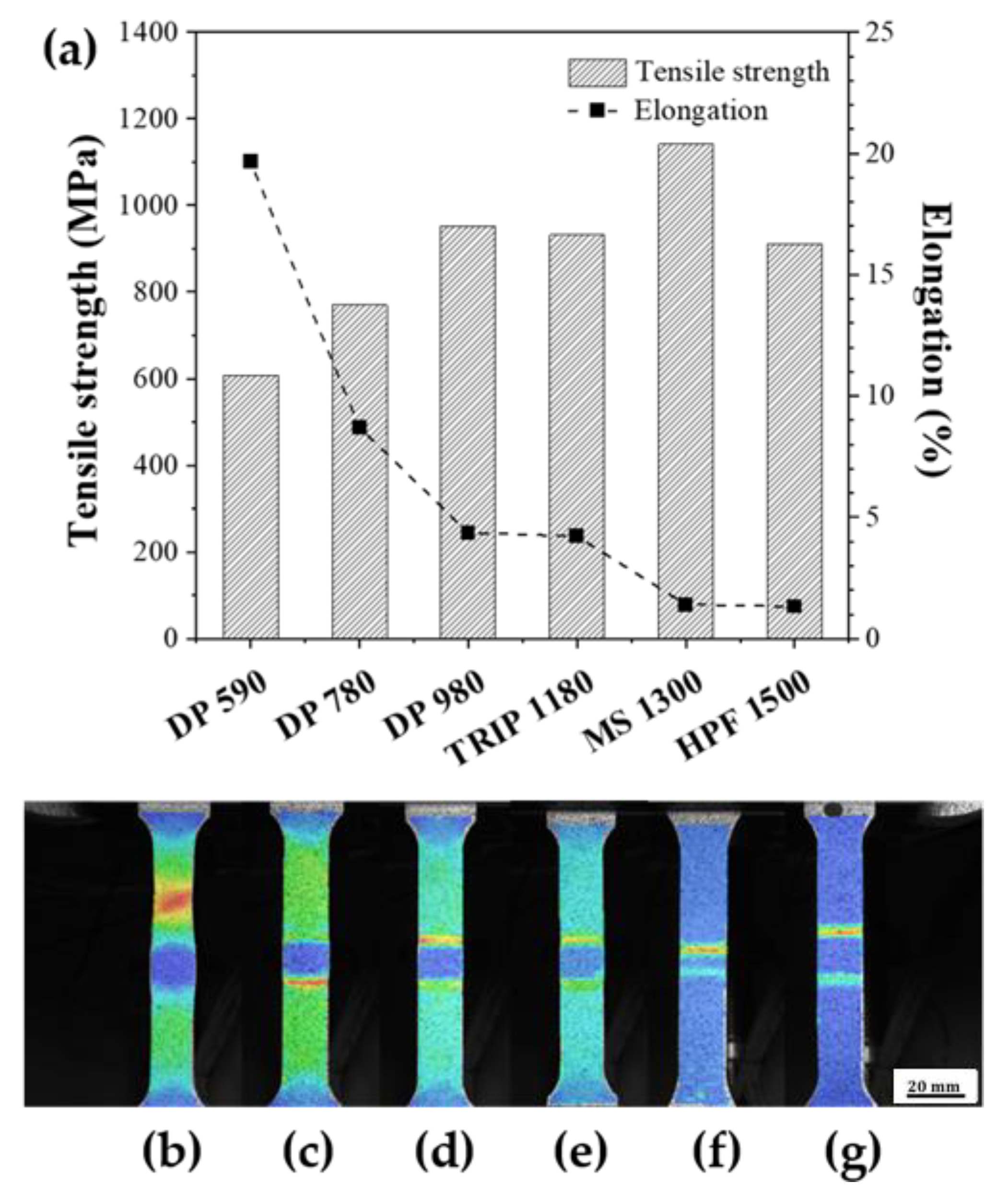
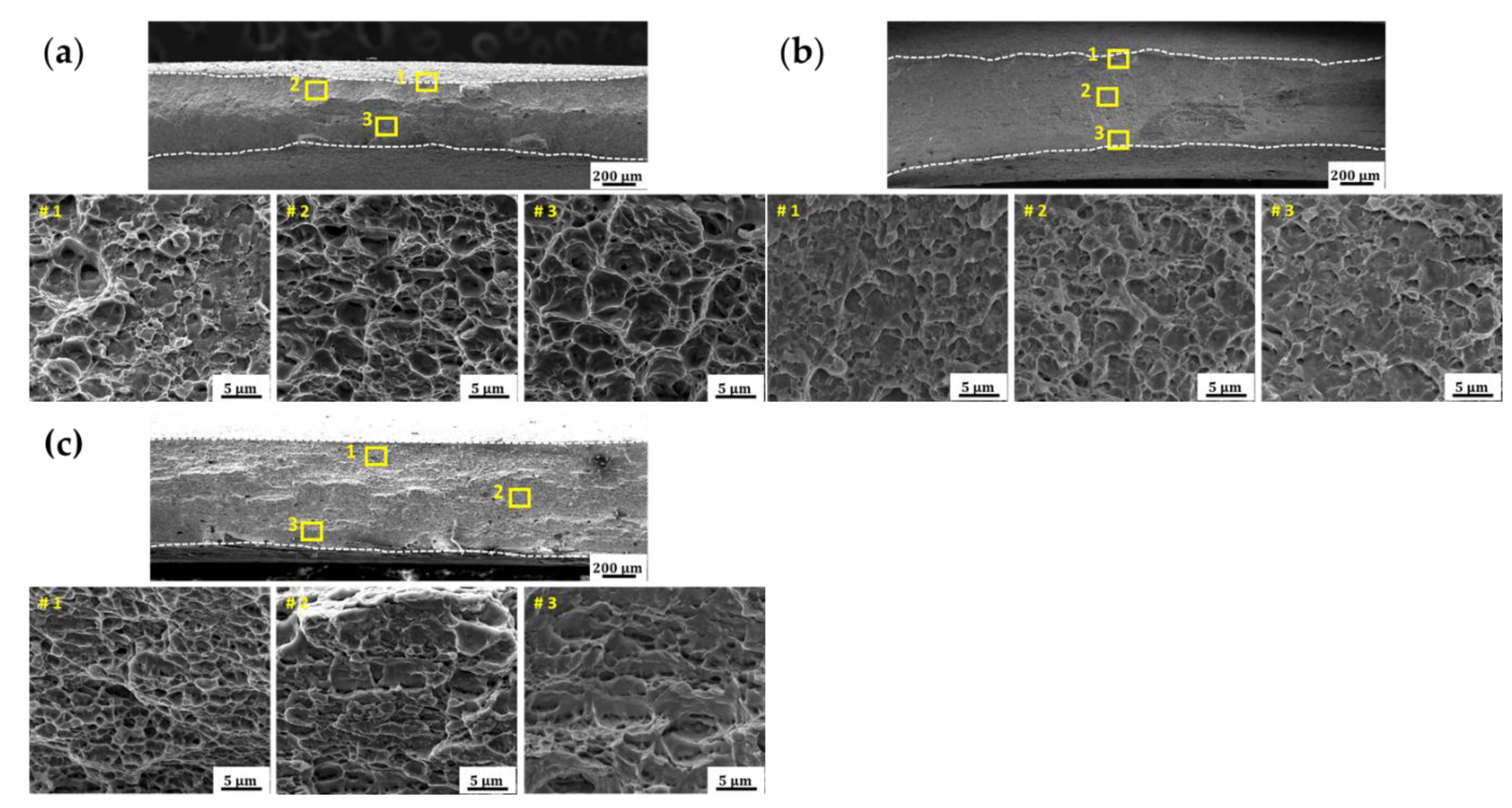
3.3. Tensile Test Results

Figure 10a shows the tensile strength and elongation of each specimen. From the TZ softening in the hardness profiles (Figure 2 and Figure 6), the weld strength is predicted to increase and then saturate with increasing BM strength. The experimental results are in good agreement with the prediction, except for the MS1300 steel, which has a higher weld strength than expected. MS1300 welds have a smaller softened zone than the others, and it seems that a narrower TZ improves the weld strength. The joint efficiency, which is defined as the ratio of the tensile strength of the welds to that of the BM, decreased with increasing strength, whereas the elongation decreased (Table 3). Materials with an elongation of less than 5% were judged to have no ductility. Therefore, it can be confirmed that the welds for DP590 and DP780 are ductile, whereas the welds for DP980, TRIP1180, MS1300, and HPF1500 are brittle. Figure 10b–g shows the results of the strain map measurement for each specimen obtained through the DIC method. In the case of the DP590 steel, stress concentration occurs in the BM, whereas the stress is concentrated in the PRZ and TZ for all the other steels. As the strength increases, the toughness and elongation decrease. Based on the strain map, the DP590 steel is observed to be broken at the base metal, and the other steels are broken in the PRZ and TZ owing to softening during welding.
Figure 11 shows the fracture surfaces of the DP590, DP780, and DP980 steels. The area indicated by the white dotted lines represents the boundary of the shear lip. The shear lip area decreased as the strength increased. In the case of the DP590 steel (Figure 11a), necking and dimples were observed. In the case of the DP780 steel (Figure 11b), river patterns were observed on the fracture surface, and ductile fracture is confirmed on the fracture surface. The DP980 steel welds (Figure 11c) are brittle with almost no ductility, and a cleavage fracture is observed on the fracture surface. Through the analysis of the fracture surface, it can be confirmed that the DP590 and DP780 steels are ductile and that the DP980 steel is brittle, consistent with the tensile test results.

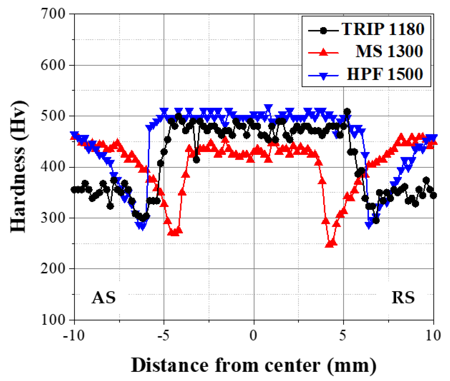
3.4. Comparison of Hardness Profiles by Process

Table 4 lists the hardness values of the RZ, PRZ, and TZ in the friction stir weldments and those from the laser weldments. In the case of the RZ of the DP590, DP780 steel laser welds, the hardness is higher than that of the friction stir welds because the cooling rate of laser welding is higher than that of FSW. On the other hand, in the case of high-strength steels, such as DP980, TRIP1180, MS1300, and HPF1500, the hardness values resulting from the FSW and laser welding processes are similar because of their high hardenability. Comparing the hardness of the PRZ and TZ in the case of FSW and laser welding, we find that softening hardly occurred in either process for DP590 and DP780. In the case of the DP980, TRIP1180, MS1300, and HPF1500 steels, the PRZ and TZ softened in both cases. However, the degree of softening for laser welding with a higher cooling rate was lower than that for FSW with a lower cooling rate.

4. Conclusions

In this study, friction stir welding was performed on high-strength steel sheets with tensile strengths ranging from 590 MPa and 1500 MPa, and their microstructures and strengths were assessed. When the strength of the BM was 980 MPa or higher, the RZ was fully martensitic, whereas evident softening could be observed in the PRZ and TZ. The softening of the PRZ and TZ could be attributed to the formation of tempered martensite, and it occurred more severely in the FSW process than in the laser welding process, wherein the cooling rate is higher.
As the strength of the material increased, the joint efficiency and elongation of the weldments decreased. The strain map results showed that for DP590 steel, the stress is concentrated in the BM, and for the other steels, the stress is concentrated in the PRZ and TZ. Because the softening of the PRZ and TZ due to the thermal history during welding deteriorated the mechanical properties, the heat input during welding and the consequent decrease in the hardness in the PRZ and TZ should be carefully managed to suppress the deterioration in the weld strength.

Author Contributions

Investigation, H.Y. and M.K.; Methodology, H.Y. and M.K.; supervision, S.Y., S.H. and C.K.; writing—original draft, H.Y. and M.K.; writing—review and editing, C.K. All authors have read and agreed to the published version of the manuscript.

Funding

This research was supported by the MOTIE (Ministry of Trade, Industry, and Energy) in Korea, under the Fostering Global Talents for Innovative Growth Program (P0008750) and Industrial Strategic Technology Development Program (20002809).

Institutional Review Board Statement

Not applicable.

Informed Consent Statement

Not applicable.

Data Availability Statement

Not applicable.

Conflicts of Interest

The authors declare no conflict of interest.

References

  1. Thomas, W.M.; Threadgill, P.L.; Nicholas, E.D. Feasibility of friction stir welding steel. Sci. Technol. Weld. Join. 1999, 4, 365–372. [Google Scholar] [CrossRef]
  2. Rai, R.; De, A.; Bhadeshia, H.K.D.H.; DebRoy, T. Review: Friction stir welding tools. Sci. Technol. Weld. Join. 2013, 16, 325–342. [Google Scholar] [CrossRef]
  3. Gibson, B.T.; Lammlein, D.H.; Prater, T.J.; Longhurst, W.R.; Cox, C.D.; Ballun, M.C.; Dharmaraj, K.J.; Cook, G.E.; Strauss, A.M. Friction stir welding: Process, automation, and control. J. Manuf. Process. 2014, 16, 56–73. [Google Scholar] [CrossRef]
  4. Mendes, N.; Neto, P.; Loureiro, A.; Moreira, A.P. Machines and control systems for friction stir welding: A review. Mater. Des. 2016, 90, 256–265. [Google Scholar] [CrossRef]
  5. Smith, C.B. Robotic friction stir welding using a standard industrial robot. In Proceedings of the Second Friction Stir Welding International Symposium, Gothenburg, Sweden, 27–28 June 2000. [Google Scholar]
  6. Cook, G.E.; Crawford, R.; Clark, D.E.; Strauss, A.M. Robotic friction stir welding. Ind. Robot Int. J. 2004, 31, 55–63. [Google Scholar] [CrossRef]
  7. Yoon, J.; Kim, C.; Rhee, S. Compensation of vertical position error using a force-deflection model in friction stir spot welding. Metals 2018, 8, 1049. [Google Scholar] [CrossRef] [Green Version]
  8. Yoon, J.; Kim, C.; Rhee, S. Performance of plunge depth control methods during friction stir welding. Metals 2019, 9, 283. [Google Scholar] [CrossRef] [Green Version]
  9. Kohn, G.; Greenberg, Y.; Makover, I.; Munitz, A. Laser-assisted friction stir welding. Weld. J. 2002, 81, 46–48. [Google Scholar]
  10. Bang, H.; Bang, H.; Jeon, G.; Oh, I.; Ro, C. Gas tungsten arc welding assisted hybrid friction stir welding of dissimilar materials Al6061-T6 aluminum alloy and STS304 stainless steel. Mater. Des. 2012, 37, 48–55. [Google Scholar] [CrossRef]
  11. Cheon, J.; Park, T.; Yoon, J.-Y.; Kim, C. Evaluation of a high-frequency induction heating assisted friction stir welding process on carbon steel sheets. J. Weld. Join. 2019, 37, 501–507. [Google Scholar] [CrossRef] [Green Version]
  12. Yoon, J.-Y.; Cheon, J.; Kim, C. Characteristic evaluation of coaxial high-frequency induction heating hybrid friction stir welding process on high strength carbon steel sheets. J. Weld. Join. 2019. [Google Scholar] [CrossRef]
  13. Cui, L.; Fujii, H.; Tsuji, N.; Nogi, K. Friction stir welding of a high carbon steel. Scr. Mater. 2007, 56, 637–640. [Google Scholar] [CrossRef]
  14. Sarkar, R.; Pal, T.K.; Shome, M. Microstructures and properties of friction stir spot welded DP590 dual phase steel sheets. Sci. Technol. Weld. Join. 2014, 19, 436–442. [Google Scholar] [CrossRef]
  15. Santella, M.; Hovanski, Y.; Pan, T.-Y. Friction stir spot welding (FSSW) of advanced high strength steel (AHSS). SAE Int. J. Mater. Manuf. 2012, 5, 382–387. [Google Scholar] [CrossRef]
  16. Lee, H.; Kim, C.; Song, J.H. An evaluation of global and local tensile properties of friction-stir welded DP980 dual-phase steel joints using a digital image correlation method. Materials 2015, 8, 8424–8436. [Google Scholar] [CrossRef]
  17. Hovanski, Y.; Santella, M.L.; Grant, G.J. Friction stir spot welding of hot-stamped boron steel. Scr. Mater. 2007, 57, 873–876. [Google Scholar] [CrossRef]
  18. Curtis, T.; Widener, C.; West, M.; Jasthi, B.; Hovanski, Y.; Carlson, B.; Szymanski, R.; Bane, W. Friction stir scribe welding of dissimilar aluminum to steel lap joints. In Friction Stir Welding and Processing VIII; John Wiley & Sons, Inc.: Hoboken, NJ, USA, 2015; pp. 163–169. [Google Scholar] [CrossRef]
  19. Kang, M.; Yoon, J.; Kim, C. Hook formation and joint strength in friction stir spot welding of Al alloy and Al-Si-coated hot-press forming steel. Int. J. Adv. Manuf. Technol. 2020, 106, 1671–1681. [Google Scholar] [CrossRef]
  20. Matsushita, M.; Kitani, Y.; Ikeda, R.; Ono, M.; Fujii, H.; Chung, Y.D. Development of friction stir welding of high strength steel sheet. Sci. Technol. Weld. Join. 2013, 16, 181–187. [Google Scholar] [CrossRef]
  21. Kang, M.; Kim, C. Corrosion assessment for boron steel weldments prepared by overlap welding and successive hot press forming processes. J. Weld. Join. 2017, 35. [Google Scholar] [CrossRef] [Green Version]
  22. Kang, M.; Jeon, I.-H.; Han, H.; Kim, C. Tensile-shear fracture behavior prediction of high-strength steel laser overlap welds. Metals 2018, 8, 365. [Google Scholar] [CrossRef] [Green Version]
  23. Xia, M.; Tian, Z.; Zhao, L.; Zhou, Y.N. Metallurgical and mechanical properties of fusion zones of TRIP steels in laser welding. ISIJ Int. 2008, 48, 483–488. [Google Scholar] [CrossRef] [Green Version]
  24. Guzman-Aguilera, J.J.; Martinez-Gonzalez, C.J.; Baltazar-Hernandez, V.H.; Basak, S.; Panda, S.K.; Razmpoosh, M.H.; Gerlich, A.; Zhou, Y. Influence of SC-HAZ microstructure on the mechanical behavior of Si-TRIP steel welds. Mater. Sci. Eng. A 2018, 718, 216–227. [Google Scholar] [CrossRef]
  25. Kim, C.-H.; Choi, J.-K.; Kang, M.-J.; Park, Y.-D. A study on the CO2 laser welding characteristics of high strength steel up to 1500 MPa for automotive application. J. Achiev. Mater. Manuf. Eng. 2010, 39, 79–86. [Google Scholar]
  26. Ahn, Y.N.; Kang, M.J.; Kim, C.H. Analysis of laser weldments for dual-phase and martensitic steel sheets for automotive applications. Defect Diffus. Forum 2014, 353, 8–12. [Google Scholar] [CrossRef]
Figure 1. Schematics of (a) FSW process, (b) tool shape used in FSW process (unit: mm).
Applsci 11 05728 g001
Figure 2. Hardness profiles for DP590, DP780, and DP980 steels.
Applsci 11 05728 g002
Figure 3. Microstructure of the DP590 steel (F: ferrite; M: martensite). (a) Joint macrograph; (b) BM; (c) TZ; (d) PRZ; (e) RZ.
Applsci 11 05728 g003
Figure 4. Microstructure of the DP780 steel (F: ferrite; B: bainite; PF: polygonal ferrite; M: martensite). (a) Joint macrograph; (b) BM; (c) TZ; (d) PRZ; (e) RZ.
Applsci 11 05728 g004
Figure 5. Microstructure of the DP980 steel (F: ferrite; TM: tempered martensite; M: martensite). (a) Joint macrograph; (b) BM; (c) TZ; (d) PRZ; (e) RZ.
Applsci 11 05728 g005
Figure 6. Hardness profiles for TRIP1180, MS1300, and HPF1500 steels.
Applsci 11 05728 g006
Figure 7. Microstructure of the TRIP1180 steel (F: ferrite; B: bainite; RA: retained austenite; TM: tempered martensite; M: martensite). (a) Joint macrograph; (b) BM; (c) TZ; (d) PRZ; (e) RZ.
Applsci 11 05728 g007
Figure 8. Microstructure of the MS1300 steel. (F: ferrite; TM: tempered martensite; M: martensite). (a) Joint macrograph; (b) BM; (c) TZ; (d) PRZ; (e) RZ.
Applsci 11 05728 g008
Figure 9. Microstructure of the HPF1500 steel (PF: polygonal ferrite; TM: tempered martensite; M: martensite). (a) Joint macrograph; (b) BM; (c) TZ; (d) PRZ; (e) RZ.
Applsci 11 05728 g009
Figure 10. Tensile strength (a) and strain maps obtained using the digital image correlation (DIC): (b) DP590, (c) DP780, (d) DP980, (e) TRIP1180, (f) MS1300, and (g) HPF1500.
Applsci 11 05728 g010
Figure 11. SEM morphology of the fracture surfaces of (a) DP590; (b) DP780; (c) DP980.
Applsci 11 05728 g011
Table 1. Chemical compositions of base materials (wt%).
Base Materials
(Thickness)
CSiMnCrSPAlNbTi
DP590 (1.0 mm)0.070.361.81------
DP780 (1.0 mm)0.060.972.25------
DP980 (1.0 mm)0.171.342.00-0.0010.016---
TRIP1180 (1.2 mm)0.161.702.310.520.0030.018
MS1300 (1.0 mm)0.200.201.50-0.0020.010.0400.0150.025
HPF1500 (1.2 mm)0.240.301.210.200.0030.014---
Table 2. FSW conditions and applied tool configuration.
Tool Rotation Speed
(rev/min)
Welding Speed
(mm/s)
Head Tilting Angle (°)Tool Geometry
Shoulder
Diameter
(mm)
Probe Diameter
(mm)
Probe
Height
(mm)
60042102.50.85
Table 3. Joint efficiency and elongation corresponding to the graph shown in Figure 10a.
DP590DP780DP980TRIP1180MS1300HPF1500
Joint efficiency (%)10098.797.178.887.860.7
Elongation (%)19.68.74.44.21.41.3
Table 4. Comparison of the microhardness of materials subjected to laser welding [25,26].
Hardness (Hv)Average Hardness
in Recrystallized Zone
Minimum Hardness in
Partial Recrystallized Zone
and Tempered Zone
Base Materials FSWLaserFSWLaser
DP590310374230225
DP780332389265252
DP980494480257287
TRIP1180475497295348
MS1300430417247270
HPF1500500493284316
Publisher’s Note: MDPI stays neutral with regard to jurisdictional claims in published maps and institutional affiliations.

