Article

Design of Bipolar Optical Code-Division Multiple-Access Techniques Using Phase Modulator for Polarization Coding in Wireless Optical Communication

1
Department of Electro-Optical Engineering, National Formosa University, Yunlin County 63201, Taiwan
2
Department of Electronic Engineering, National Formosa University, Yunlin County 63201, Taiwan
*
Author to whom correspondence should be addressed.
Appl. Sci. 2021, 11(13), 5955; https://doi.org/10.3390/app11135955
Submission received: 16 May 2021 / Revised: 17 June 2021 / Accepted: 22 June 2021 / Published: 26 June 2021
(This article belongs to the Special Issue Optical Communication Networks: Progress and Challenges)

Abstract

:
In this study, a bipolar optical code-division multiple-access (Bi-OCDMA) technique based on spectral amplitude coding (SAC) was proposed by using a phase modulator to realize polarization coding through a free-space optical (FSO) channel. Various types of noise, such as amplified spontaneous emission (ASE) noise, thermal noise, and shot noise, were included in the simulation to approach the real application. The first simulation, utilizing a modified M-sequence as signature code, demonstrated that the proposed Bi-OCDMA system could be implemented in FSO communication. The proposed Bi-OCDMA scheme improves the transmission rate and power efficiency compared with the previous scheme. The structure of the proposed system alleviates multiple-access interference (MAI) with a simple and cost-effective design. The second simulation observed the performance of the proposed Bi-OCDMA for two users with several well-known SAC codes, i.e., multi-diagonal (MD) code, modified quadratic congruence (MQC) code, modified maximum length sequence (M-sequence) code, and Walsh–Hadamard code, in extreme weather conditions, both for additive white Gaussian noise (AWGN) and turbulence-induced fading channel. The simulation results indicated that the Walsh–Hadamard code has superior performance compared to other codes. The results show the MD code can be implemented in the proposed Bi-OCDMA scheme for a medium-distance FSO.

1. Introduction

The demands of the fifth generation (5G) network are becoming challenging due to a significant increase in complexity. The 5G network requires ultra-low deterministic latency to operate normally, and must be kept running and maintained at a relatively low cost from a commercial perspective. From 2010 to 2030, the explosive growth of data traffic (expected to be approximately 20,000-fold) will require communication network technology to provide higher coverage and availability, in addition to denser networks [1]. Future networks will also need to support the continuous appearance of new services, such as machine-to-machine (M2M) applications and Internet of Things (IoT) applications.
Due to their high bandwidth, low latency, accurate synchronization, high reliability, and flexible application, optical networks are among the promising technologies that can meet the increasing demands of the upcoming 5G technology. However, in several applications, particularly in the last mile, it is costly to lay optical fiber cables for users. Free-space optical (FSO) communication has become one of the preferable methods with comparable data rates and very low error rates compared to optical fiber cables, although the biggest challenge is power attenuation due to atmospheric turbulence under various weather conditions. FSO communication is a line-of-sight wireless communication scheme designed with short optical links, typically in the range of 200–2000 m [2]. Regarding communications, FSO technology is considered to be a part of wireless optical communications applications. To fulfill the 5G or higher network technology requirements, the cross-spectrum and cross-medium of optical fibers, millimeter waves (mmWave), and optical wireless communication schemes were proposed in [3]. The proposed concept can achieve satisfactory performance by transmitting a 40 Gb/s radio signal over the hybrid system in the 100 GHz band. Different hybrid methods were investigated in [4] with a hybrid K-band (25 GHz) microwave photonic link (MPL) configuration, including optical fibers, FSO, and radio frequency (RF) wireless channels. The experimental and simulation results reported in [4] proved the feasibility of the proposed hybrid system for 5G wireless networks with the advantages of lower demand for high-frequency equipment.
Furthermore, a substantial component of FSO communication to support dense networks is the multiplexing technology. The most commonly used multiplexing technology in optical systems is wavelength division multiplexing (WDM), which enables the use of different light wavelengths to send data over the same channel. The disadvantage of WDM is spectral dispersion. With the limitation of spectral bandwidth resources, many studies have focused on improving WDM performance. In 2020, Chakkour et al. verified a novel optical transmission model with the split-step Fourier and transfer matrix methods to improve the performance of WDM for long-haul optical transmission systems [5]. Another study implemented a novel high-speed long-haul WDM-based inter-satellite optical wireless communication system. In the proposed scheme, differential quadrature phase-shift keying-polarization-shift keying was employed as an optical orthogonal modulation scheme to improve the spectral efficiency of the WDM [6].
The other multiplexing technique that implements effective spectrum sharing for multi-user schemes in optical networks is time-division multiplexing (TDM). In this technique, a single channel or band is divided into time slots, which is especially useful for compressed video and other high-speed data. The performance of the TDM is significantly affected by the optical clock distribution and synchronization [7]. In 2020, Mishra et al. proposed the delay-controlled and energy-efficient clustered (DEC) time-division multiple access (TDMA) to reduce the delay and increase the energy efficiency in fiber wireless access networks (FiWi) by utilizing time stamping for synchronization. The proposed DEC TDMA shows an improvement in delay performance with the implementation of dynamic bandwidth allocation while providing data slots in TDMA [8].
A promising multiplexing technique to achieve high-speed connectivity with large bandwidth is optical code-division multiple access (OCDMA), which has received increasing attention in optical communication due to its asynchronous transmission, flexibility, security, and scalability. Among OCDMA technologies, spectral amplitude coding (SAC) has been proposed to minimize the impact of multi-user interference and suppress the effect of phase-induced intensity noise (PIIN) with fixed in-phase cross-correlation [9]. In 2018, Mottaleb et al. utilized a single photodiode (SPD) detection technique to overcome both PIIN and multiple-access interference (MAI) to increase the performance of SAC-OCDMA [10]. Aldhaibani et al. proposed a hybrid system that combines the conventional SAC-OCDMA and orthogonal frequency division multiplexing (OFDM) to improve the performance of SAC-OCDMA at high data rates and propagate with high fidelity over fiber links [11].
In the demodulation scheme of optical signals, OCDMA can be divided into two categories: non-coherent and coherent OCDMA. The non-coherent OCDMA system uses light intensity to encode optical signals. A commonly used encoding method is unipolar encoding, which has the characteristics of simple design and low cost; however, this scheme is only suitable for low data rates such as voice data. Meanwhile, coherent systems encode the input light phase using a matching filter to change the phase of an optical signal. The autocorrelation intensity peak in the coherent system after the square-law detection with the photodetector is superior to the non-coherent scheme, and demonstrates the excellent correlation properties of coherent OCDMA. Zefreh et al. [12] proposed a power-cubic nonlinear preprocessor for a spectral-phase-encoded ultrashort light pulse optical code-division multiple-access system. The numerical results proved the superiority of the proposed system in improving the coherent SAC-OCDMA system performance, especially in high-power scenarios in which MAI becomes the dominant noise. Bipolar coding in a coherent system is advantageous in terms of spectral efficiency [13]. Therefore, bipolar coding is suitable for high-speed data transmission and real-time applications. The performance of bipolar encoding is better than that of unipolar encoding [14]. Bipolar codes can also be implemented in the non-coherent OCDMA system to stabilize the decision threshold for the improvement of bit error rate (BER) performance [15].
Several methods have been investigated to improve the performance of bipolar encoding; one of these uses a two-code keying scheme that exhibits an enhanced BER performance compared to the existing unipolar encoding with a direct detection technique [16]. Regarding security, in 2018, Patel et al. proposed a novel bipolar code based on a double-weight code pattern with a reconfigurable encoder design. Code reconfiguration at the transmitting end provides code security against an eavesdropper at the transmitter and receiver ends [17]. In 2020, Gupta et al. proposed a novel bipolar double-weight coding scheme in the spectral domain to make the system more secure against the eavesdropping situation [18].
For transmission over an atmospheric turbulence channel, the polarization state of a light beam is the most stable parameter compared to the amplitude and phase [19]. The polarization domain has the potential to improve both system capacity and spectral efficiency (SE) by utilizing the state of polarization (SOP) of light [20]. A spectral-polarization coding OCDMA configuration effectively suppresses PIIN. Our previous work [21] used horizontal and vertical polarization states to generate bipolar data. By employing the switch as user data to polarize the optical signals with a series of fiber Bragg gratings (FBGs) and optical circulators as the decoding devices, the proposed scheme successfully mitigates MAI in FSO communication systems. The system drawbacks due to the limitation in the speed of the optical switch caused the limited transmission rate of the system [21]. In our subsequent work [22], another bipolar optical code-division multiple-access (Bi-OCDMA) scheme with a dual electro-optical modulator (EOM) was proposed to improve the transmission rate and spectral-polarization coding performance compared to the switch method in a previous study. In this method, the properties of the two EOMs need to be kept as similar as possible; moreover, the signal power is limited because the proposed scheme only transmits the signal with a wavelength corresponding to chip “1” in the signature code [22].
However, for the modulation of optical signals, several techniques have been proposed; one of these is phase modulation, which is a modulation technique that encodes a message signal as variations in the instantaneous phase of a carrier wave. The phase modulator is the simplest EOM with superiority in improving immunity toward noise. In 2014, Gao et al. [23] utilized a single-phase modulator for the simultaneous generation of time-domain spectral phase encoding/decoding (SPE/SPD) and differential phase-shift keying data modulation in the OCDMA system. The scheme proved that the flexibility and confidentiality of the OCDMA system can be improved by using a single-phase modulator [23].
In addition to the system design, channel impairments, such as atmospheric conditions and turbulence-induced fading, affect the performance of wireless optical communication. In [24], different detection schemes in SAC-OCDMA systems were investigated in the presence of different atmospheric impairments. The simulation results indicate that the SPD technique has the best performance among the detection methods. Another performance analysis of climatic turbulence was simulated in [25] with the hybrid SAC-OCDMA-OFDM method to reduce the signal fluctuations and quality degradation caused by weather conditions. The simulation results showed that the SPD detection receiver achieved better BER performance than the modified AND detection receiver. The results denoted in [25] also revealed that the proposed triangular matrix-zero cross-correlation code achieved better BER performance than the proposed pulse shifting substitution-zero cross-correlation code.
Furthermore, different signature codes for SAC-OCDMA have been proposed and investigated in many studies. Several well-known SAC codes were adopted for the simulation in this study and are listed as follows:
  • Modified quadratic congruence (MQC) code: With fixed in-phase cross-correlation, the MQC code resolves the interference, which is the main factor limiting the performance of the OCDMA system [26].
  • Walsh–Hadamard code: The Walsh–Hadamard code maps messages of length n to codewords of length 2n, and each non-zero codeword has a Hamming weight of exactly 2n−1 [27,28].
  • Maximum length sequence (M-sequence) code: M-sequence code is a type of pseudorandom binary sequence with length 2m−1. The bit sequences can be generated using maximal linear feedback shift registers and periodically reproduce every sequence of bits that can be represented by the shift registers [29].
  • Multi-diagonal (MD) code: Another SAC code imposing the diagonal property is the MD code, which also has the property of zero cross-correlation. It has been shown that the MD code has been implemented in many OCDMA systems [30,31,32,33].
In this study, a Bi-OCDMA system for FSO communication was implemented by utilizing the phase modulator for polarization coding with the SAC code as the signature code. The main contributions of this study are as follows:
  • A simple, cost-effective, and moderate security scheme for a bipolar OCDMA system with a phase modulator was proposed for FSO communication. The proposed system maintains the SAC-OCDMA principles, which eliminate the MAI problem. The proposed system improves the transmission rate compared to the previous scheme with an optical switch [21]. Moreover, because all signature codes were utilized to transmit data, the proposed Bi-OCDMA improved power efficiency compared to our previous scheme with dual EOM [22].
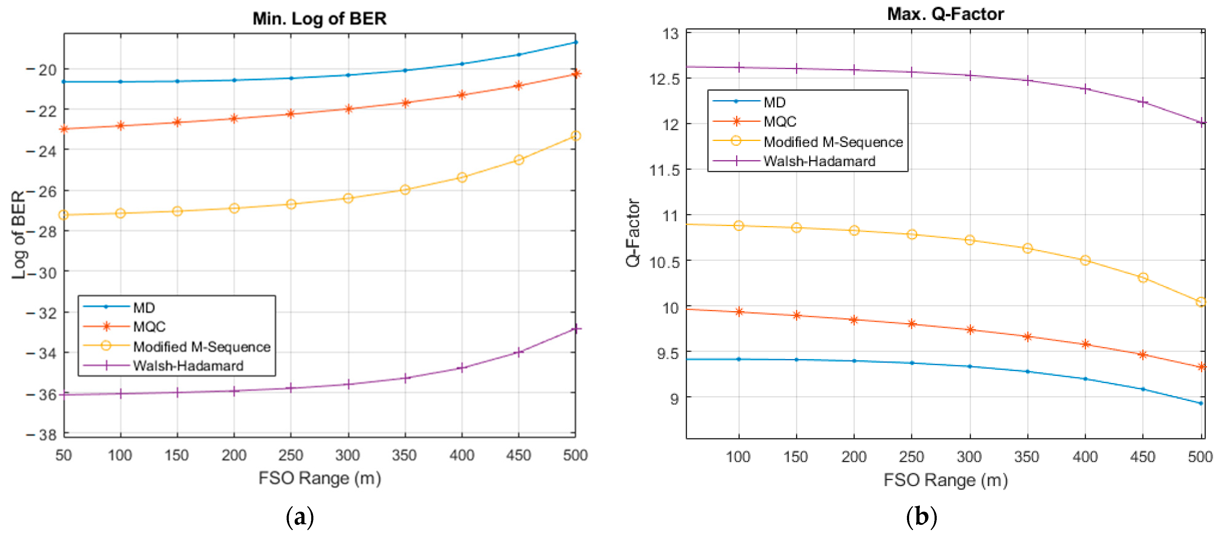
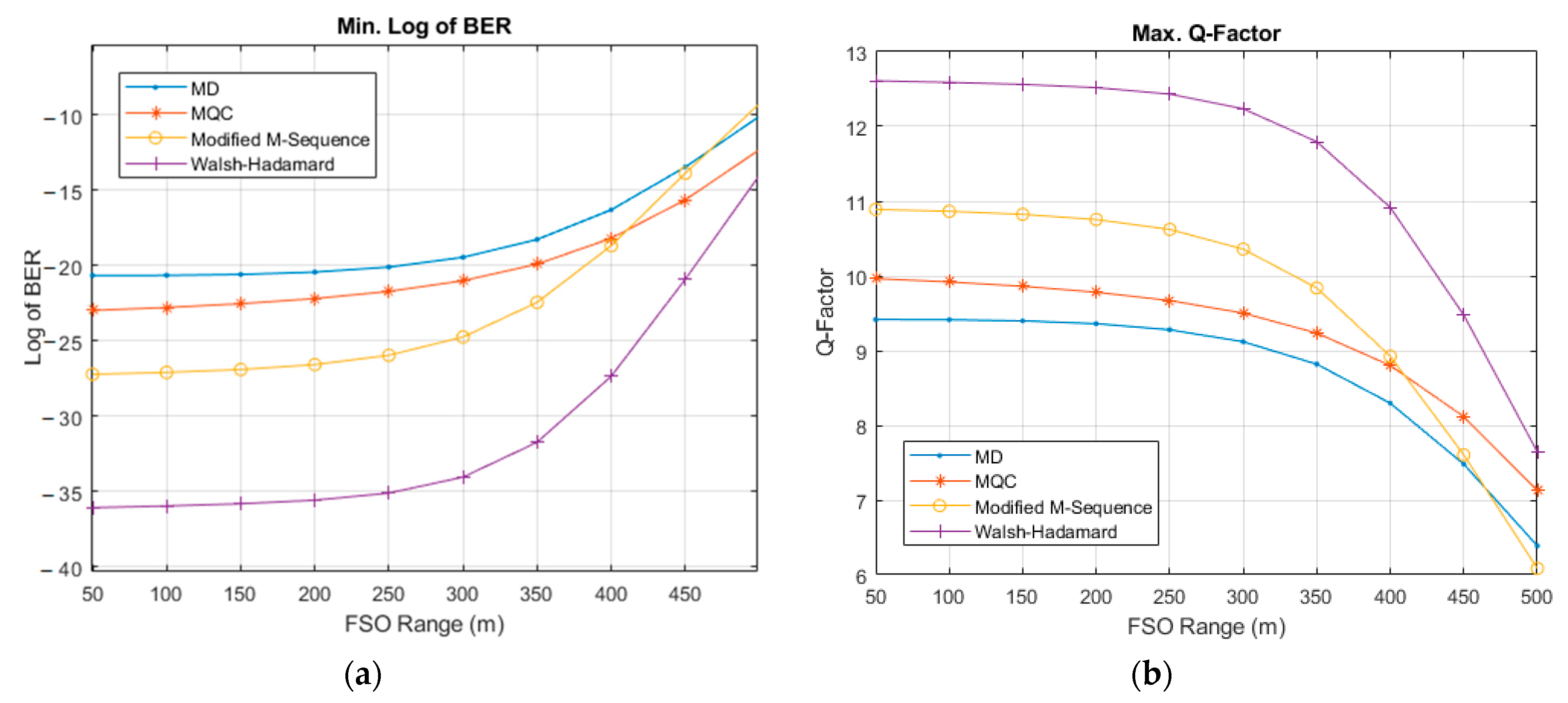
  • The proposed system was investigated under extreme weather conditions using different SAC-OCDMA codes. The performance measurements were observed in terms of BER and quality factor (Q-factor), both for additive white Gaussian noise (AWGN) and AWGN with a fading channel.
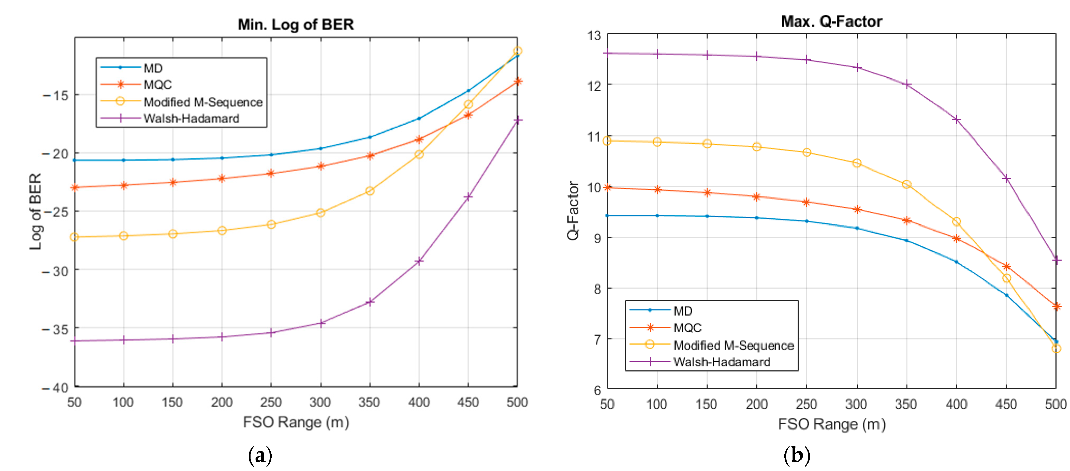
  • The proposed Bi-OCDMA architecture was further tested under different turbulence-induced fading conditions, and a performance comparison was performed between different SAC-OCDMA. The fading model implemented the gamma–gamma fading channel model.
The remainder of this paper is organized as follows. Section 2 introduces the proposed Bi-OCDMA system, including the system architecture of encoding and decoding diagrams, the derivation of the correlation function, and the multi-user structure. Section 3 presents the simulation setup and results, including the feasibility of the proposed system, performance measurement, and comparison of the Bi-OCDMA systems with extreme weather conditions in AWGN and turbulence-induced fading channels. Finally, the work is concluded in Section 4, and prospective future work is noted.

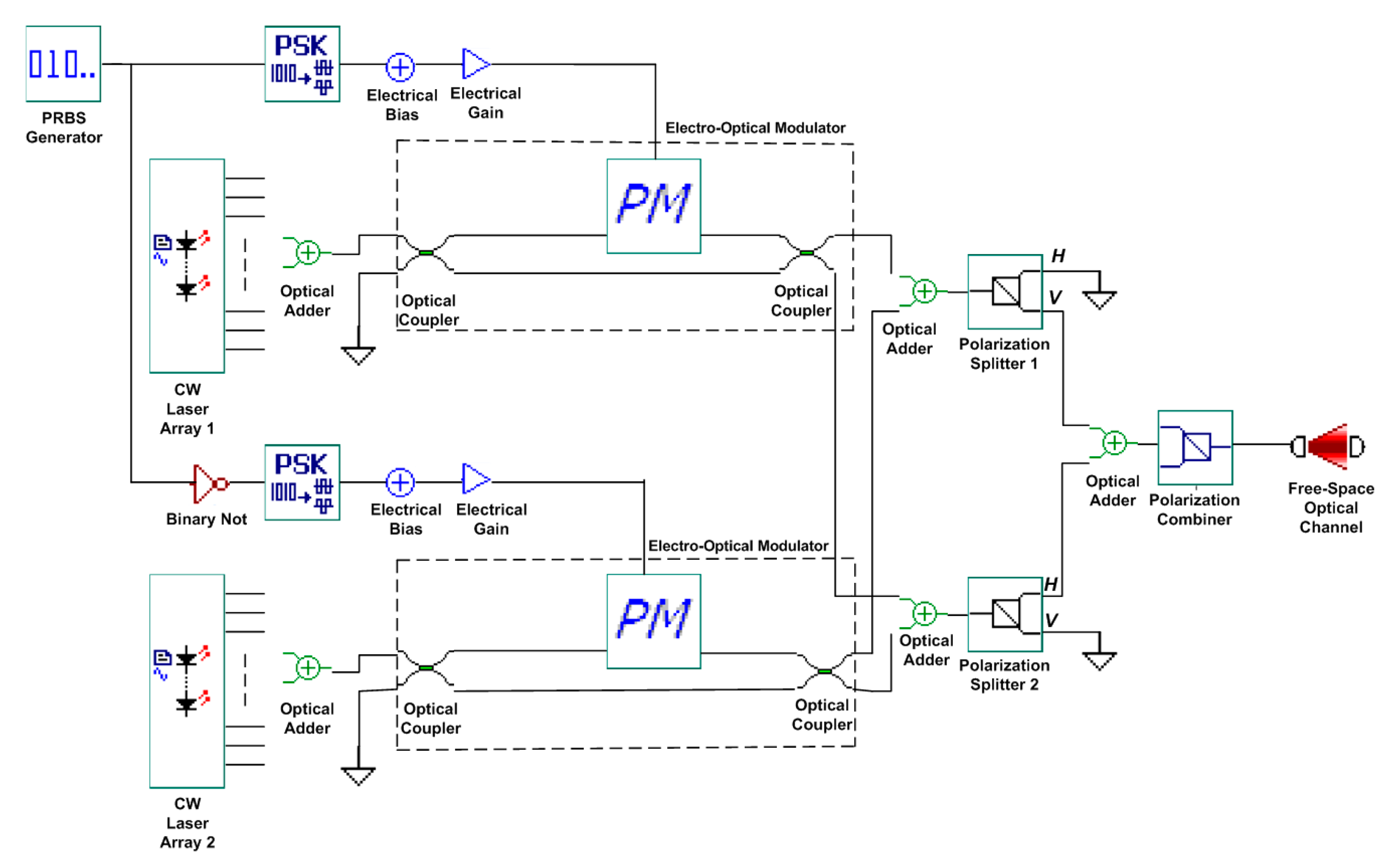
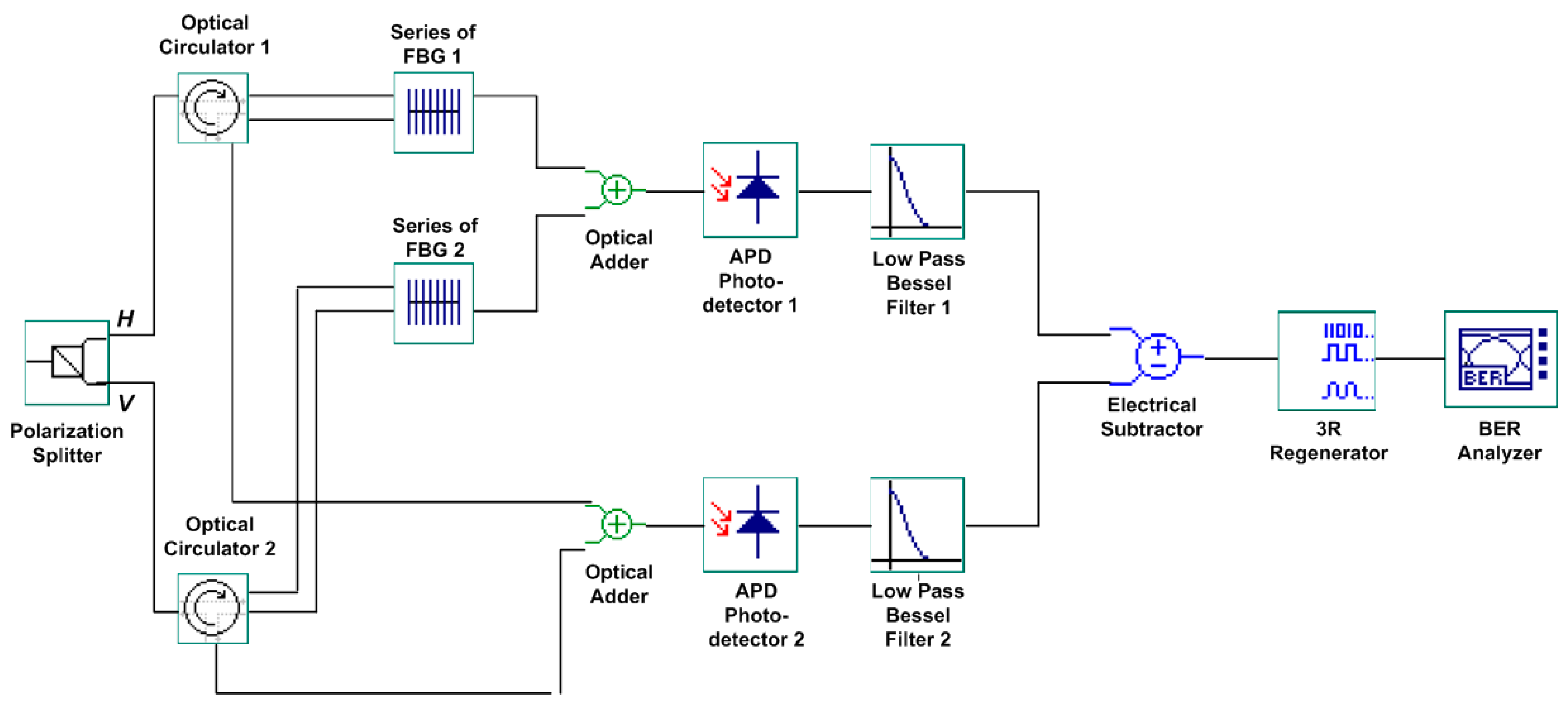
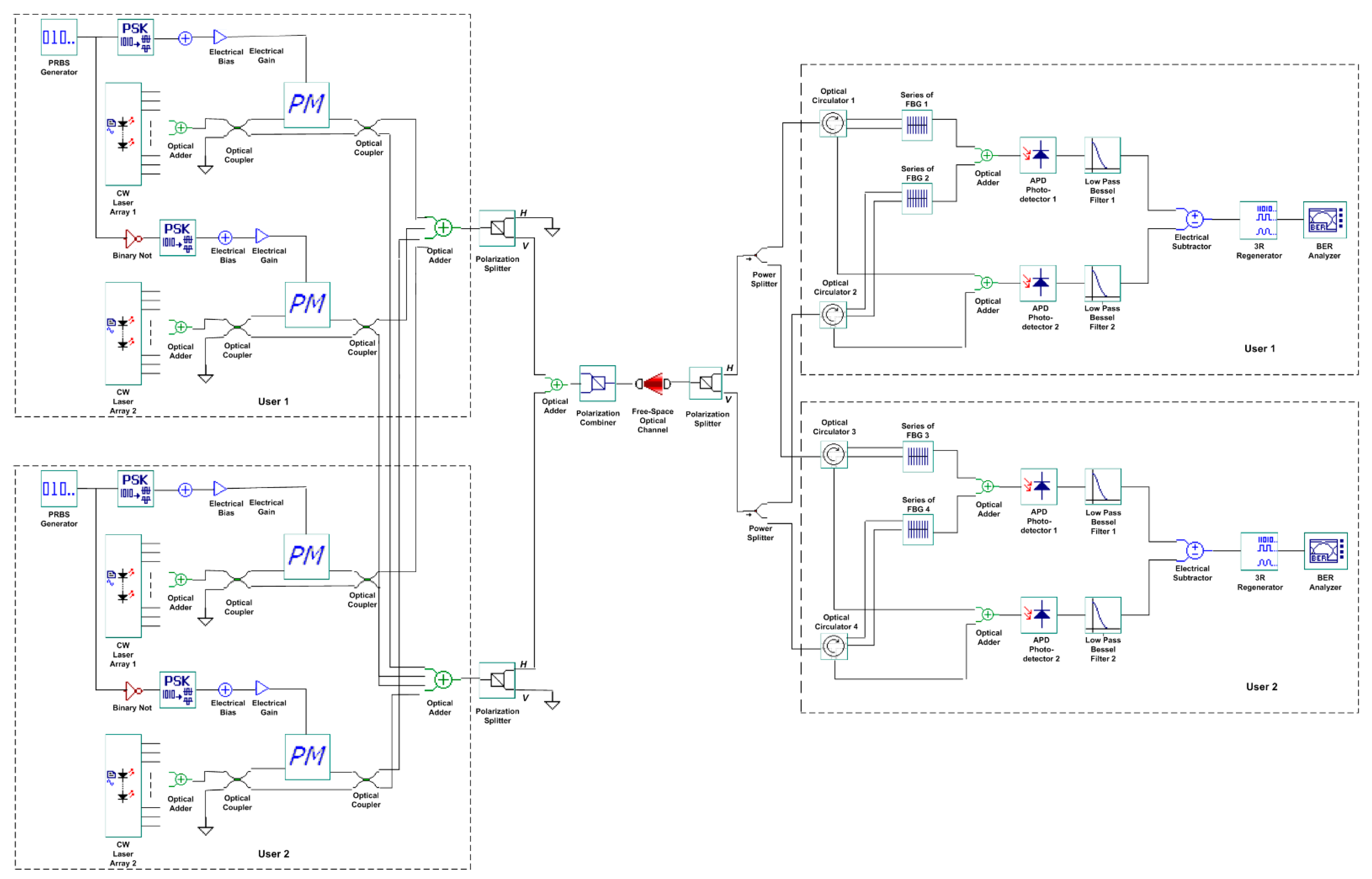
2. The Proposed Bi-OCDMA System

The proposed Bi-OCDMA technique was developed to transmit bipolar data signals over a common FSO channel. Each user data is created using a pseudorandom bit sequence (PRBS). A phase-shift keying (PSK) pulse generator along with electrical bias and electrical gain were applied to generate the modulation signal. For data processing, a phase modulator is used to encode the data bit of each user into an optical signal, which is transmitted to the decoder end through an FSO channel. Polarization splitters are utilized as polarization-shift keying devices. An optical circulator and a series of uniform FBGs were used as decoder devices. The balanced photodetection method was used to detect differences in the optical power between two optical signals using two photodiodes. In the proposed Bi-OCDMA scheme, the MAI effect was alleviated using a balanced photodetection method.
In the single-user scheme, a family of M-sequences that forms all sequences of the same length is used in the Bi-OCDMA schemes. To maintain the cross-correlation property for MAI elimination in the proposed scheme, the zero-padding method was implemented by adding zeros after the last bit of the original M-sequence. The resulting code family is named the modified M-sequence in the remainder of this paper. Let X 1 be a codeword from the modified M-sequences as follows:
X 1 = [ x 1 ( 1 ) ,   x 1 ( 2 ) , ,   x 1 ( N ) , z p ]
where x k ( i ) is the i-th element of the k-th codeword of the modified M-sequence, N is the code length of the modified M-sequence, and z p is the zero-padding element. Subsequently, the cyclic property of M-sequences is used to generate codewords of the same length using N and equation of X ( k + 1 ) = T k X 1 , where T is the shifting operator vectors cyclically to the right by one place, and k is the number of cyclic shifts to the right side.
The implementation of polarization coding and modulation techniques for Bi-OCDMA schemes using modified M-sequence codes can be described as follows: when the data bit of the k-th user is “1,” the transmitted optical signal is modulated with the vertical (or horizontal) polarization state if the chip of codeword is “0” (or “1”), respectively. However, when the data bit of the k-th user is “0,” if the chip of codeword is “0” (or “1”), the transmitted optical signal is modulated with the horizontal (or vertical) polarization state, respectively.
For example, the proposed modified M-sequence code of length 8 in the bipolar scheme can be expressed using the matrix as follows:
X = [ 1 1 1 1 1 1 1 1 1 1 1 1 1 1 1 1 1 1 1 1 1 1 1 1 1 1 1 1 1 1 1 1 1 1 1 1 1 1 1 1 1 1 1 1 1 1 1 1 1 1 1 1 1 1 1 1 ] = [ 1 0 1 1 1 0 0 0 0 1 1 1 0 0 1 0 1 1 1 0 0 1 0 0 1 1 0 0 1 0 1 0 1 0 0 1 0 1 1 0 0 0 1 0 1 1 1 0 0 1 0 1 1 1 0 0 ] [ 0 1 0 0 0 1 1 1 1 0 0 0 1 1 0 1 0 0 0 1 1 0 1 1 0 0 1 1 0 1 0 1 0 1 1 0 1 0 0 1 1 1 0 1 0 0 0 1 1 0 1 0 0 0 1 1 ] = C V C ¯ H
In Equation (2), x k denotes the k-th row in the modified M-sequence matrix, which can be split into two unipolar codes, c k V and c ¯ k H . These two codes denote the positive and negative elements of x k , and form a complementary pair in the set {0, 1}. In this approach, x k is sent a data bit “1” for the k-th user, where the complement row of x k (denoting x ¯ k ) is transmitted for a data bit “0” of the k-th user. The notation ( C V C ¯ H ) represents the matrix formed where all users sent a data bit “1.” Subsequently, the modified M-sequence matrix can be mapped to the wavelength domain, characterized by two orthogonal polarization states (vertical and horizontal). The first and second matrices are assigned to the vertical ( C V ) and horizontal ( C ¯ H ) polarization states, respectively. Similarly, the complement matrix of X can be decomposed into the following form:
X ¯ = [ 1 1 1 1 1 1 1 1 1 1 1 1 1 1 1 1 1 1 1 1 1 1 1 1 1 1 1 1 1 1 1 1 1 1 1 1 1 1 1 1 1 1 1 1 1 1 1 1 1 1 1 1 1 1 1 1 ] = [ 0 1 0 0 0 1 1 1 1 0 0 0 1 1 0 1 0 0 0 1 1 0 1 1 0 0 1 1 0 1 0 1 0 1 1 0 1 0 0 1 1 1 0 1 0 0 0 1 1 0 1 0 0 0 1 1 ] [ 1 0 1 1 1 0 0 0 0 1 1 1 0 0 1 0 1 1 1 0 0 1 0 0 1 1 0 0 1 0 1 0 1 0 0 1 0 1 1 0 0 0 1 0 1 1 1 0 0 1 0 1 1 1 0 0 ] = C V ¯ C H
Therefore, the optical signal R k sent from the encoder of the k-th user can be derived as:
R k = b k ( c k V c ¯ k H ) + ( 1 b k ) ( c ¯ k V c k H )
where b k { 0 , 1 } , c k V and c k H are the k-th codewords for encoding with the vertical and horizontal polarization states, respectively. That is, if b k = 1, the spectrum of the coded signal corresponds to ( c k V c ¯ k H ). Similarly, the spectrum of the coded signal is ( c ¯ k V c k H ) if b k = 0.
Table 1 shows the modified M-sequence code of length eight with bipolar schemes. The symbols H and V represent the optical signals with horizontal and vertical polarization states, respectively. Based on these derivations, a corresponding FSO system using Bi-OCDMA schemes can be constructed.
To implement modified M-sequence codes with length N in the proposed schemes, the results of the following correlation must be obtained:
θ x x ( k , l ) = i = 1 N ( c k V ( i ) c ¯ k H ( i ) ) ( c l V ( i ) c ¯ l H ( i ) ) = { N ,   k = l N / 2 ,   k l
θ x x ¯ ( k , l ) = i = 1 N ( c k V ( i ) c ¯ k H ( i ) ) ( c ¯ l V ( i ) c l H ( i ) ) = { 0 ,   k = l N / 2 ,   k l
The correlation properties in Equations (5) and (6) verified that the modified M-sequence codes can be implemented in the proposed system to alleviate MAI with a balanced photodetection method.
Figure 1 illustrates the design of the proposed encoder, which is composed of two continuous wave (CW) laser arrays as the light source, a PRBS generator as the bit sequence generator, two sets of electrical bias, electrical gain, and PSK pulse generator as the modulation signal, two-phase modulators for optical signal modulation, four optical couplers, several optical adders, an inverter, two polarization splitters (0° and 90°) for polarization coding, and a polarization combiner.
First, two CW laser arrays are employed to emit specific wavelengths based on the assigned modified M-sequence codeword, where CW laser array#1 (or #2) sends out the wavelength correlated with chip “1” (or “0”) of the codeword depending on the users’ data bit of “0” (or “1”). As shown in Table 1, because the modified M-sequence codeword X1 = [1 0 1 1 1 0 0 0] is assigned to user#1, the wavelengths of CW laser arrays #1 and #2 are (λ1, λ3, λ4, λ5) and (λ2, λ6, λ7, λ8), respectively. Based on the user data bit, electrical signals are generated by the PSK pulse generator. Because the in-phase output of the PSK pulse generator is −1 and 1, electrical bias and electrical gain are utilized to normalize it to 0 and 1 for the modulating signal of the phase modulator. Next, the electrical signal is sent to the EOM for optical signal modulation. The output optical signals from the phase modulator can be formulated as follows:
E o u t , P M ( t ) = E i n , P M ( t ) . exp ( j . Δ Q . X ( t ) )
where E i n , P M ( t ) denotes the electrical input signal, Δ Q is the phase deviation, and X ( t ) is the electrical input. The modulated signals are then distributed to one of the outputs from the optical coupler, depending on the user data bit. The output of the optical coupler can be expressed as:
( E 1 o u t , C E 2 o u t , C ) = ( α 1 c p j c p j c 1 c ) ( E 1 i n E 2 i n )
where α denotes the additional loss, p is the conjugate parameter, c denotes the coupling coefficient, and E i n is the input optical signal.
When the data bit of the user is “1” (or “0”), only the first (or second) output of the optical couplers will have the signals and pass into the upper (or lower) polarization splitter to polarize the signals into the horizontal (or vertical) polarization state. These polarized signals are then combined through the polarization combiner. For example, if the data bit of user#1 is “0,” the polarization combiner output corresponds to [λ1, λ3, λ4, λ5]H and [λ2, λ6, λ7, λ8]V; however, if the bit of user#1 is “1,” the polarization combiner output corresponds to [λ2, λ6, λ7, λ8]H and [λ1, λ3, λ4, λ5]V. Finally, the output of the encoder is transmitted via an FSO channel.
Figure 2 illustrates the structure of the proposed Bi-OCDMA decoder, which is composed of a polarization splitter, two optical circulators, two series of uniform FBGs, two optical adders, two photodetectors, two low-pass Bessel filters, and one electrical subtractor to complete the bipolar scheme with balanced photodetection by subtracting the upper and lower signals to mitigate the MAI.
The received optical signals are depolarized through the polarization splitter and then sent to the following two circulators, whose ports #2 are connected to two series of uniform FBGs. The wavelengths of these two series of uniform FBGs are determined using the assigned codewords. For example, the series of upper (or lower) uniform FBGs reflect the central wavelengths of λ1, λ3, λ4, and λ5 (or λ2, λ6, λ7, and λ8) that correspond to chip “1” (or “0”) of the codeword X1 = [1 0 1 1 1 0 0 0] in the uniform FBG decoder for user#1. The reflected signals subsequently enter port#3 of the circulator, whereas the transmitted signals of the two series of uniform FBGs are collected into the upper optical adder. A lower optical adder is used to gather optical signals from port#3 of each of the two optical circulators.
From Equation (4), the received vertical ( R V ) and horizontal signal ( R H ) can be derived as follows, where the received optical signal ( R ) is equal to R V + R H [21]:
R V = k = 1 K b k c k V + ( 1 b k ) c ¯ k V   and   R H = k = 1 K b k c ¯ k H + ( 1 b k ) c k H
where k denotes the number of active users, R V is the sum of the optical signal with vertical polarization, and R H represents the sum of the optical signal with horizontal polarization. Based on the above equation, the optical signal ( R V ) with specific wavelengths corresponding to the position of the “1s” of c ¯ k V is reflected by the k-th user’s uniform FBGs-based decoder, and then arrives at the lower optical adder. Simultaneously, the optical signal ( R V ) with remainder wavelengths corresponding to the position of the “1s” of c k V is sent to the upper optical adder. Conversely, the optical signal ( R H ) with specific wavelengths corresponding to the position of the “1s” of c k H arrives at the upper optical adder after a series of lower uniform FBGs. Concurrently, the optical signal ( R H ) with the reflected wavelengths is sent to the lower optical adder.
The output signals of the upper and lower optical adders are then passed to the photodetectors for electrical subtraction to complete the balanced detection. This approach is detailed in the following equation:
θ x h ( k , l ) θ x h ¯ ( k , l ) = { N ,   if   x = h ,   k = l N ,   if   x = h ¯ ,   k = l 0 ,   otherwise  
where h and h ¯ denote the assigned and complementary optical codewords of the desired user, respectively. Finally, a 3R regenerator was used to determine the data bit of the desired user. The BER and Q-factor were then measured using a BER analyzer. Mathematically, the BER of the proposed Bi-OCDMA can be evaluated using [16]:
B E R = 1 2 e r f c ( S N R 2 )
where S N R is the signal-to-noise ratio of the proposed system and e r f c denotes the complementary error function in time, which can be calculated as [34]:
e r f c = 2 π x exp ( t 2 ) d t
In this simulation, the minimum log of the BER was adopted instead of the minimum BER to simplify the system performance analysis [35]:
m i n { l o g ( B E R ) } = log 10 B E R
The correlation between the BER and Q-factor can be derived as [36,37]:
B E R = 1 2 e r f c ( Q 2 )
Figure 3 shows the proposed encoder/decoder architecture for a multi-user scheme with two users. The higher multi-user scheme can be expanded with the same architecture as that of the single-user scenario.

3. Simulation Setup and Results

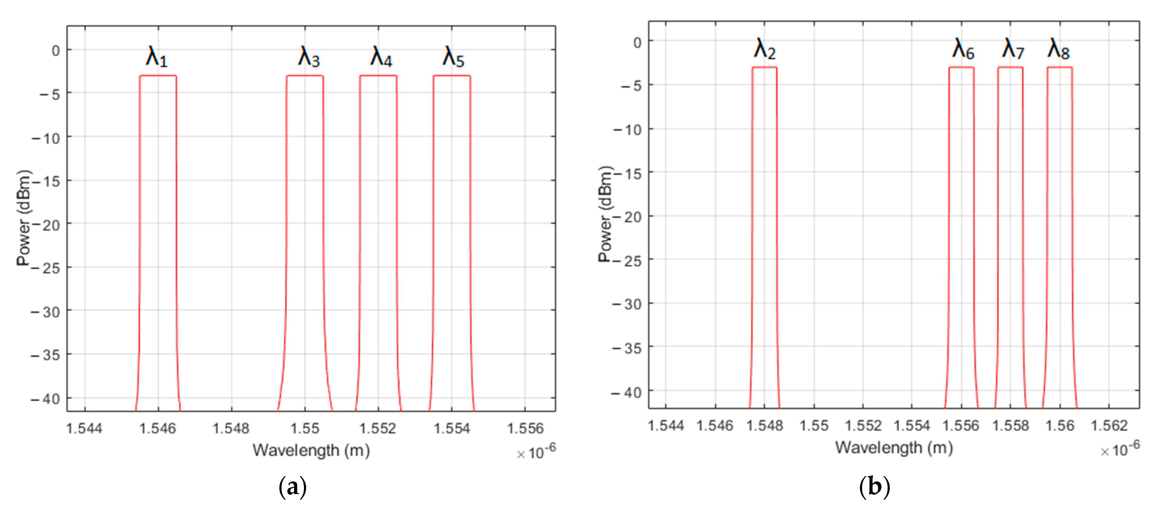
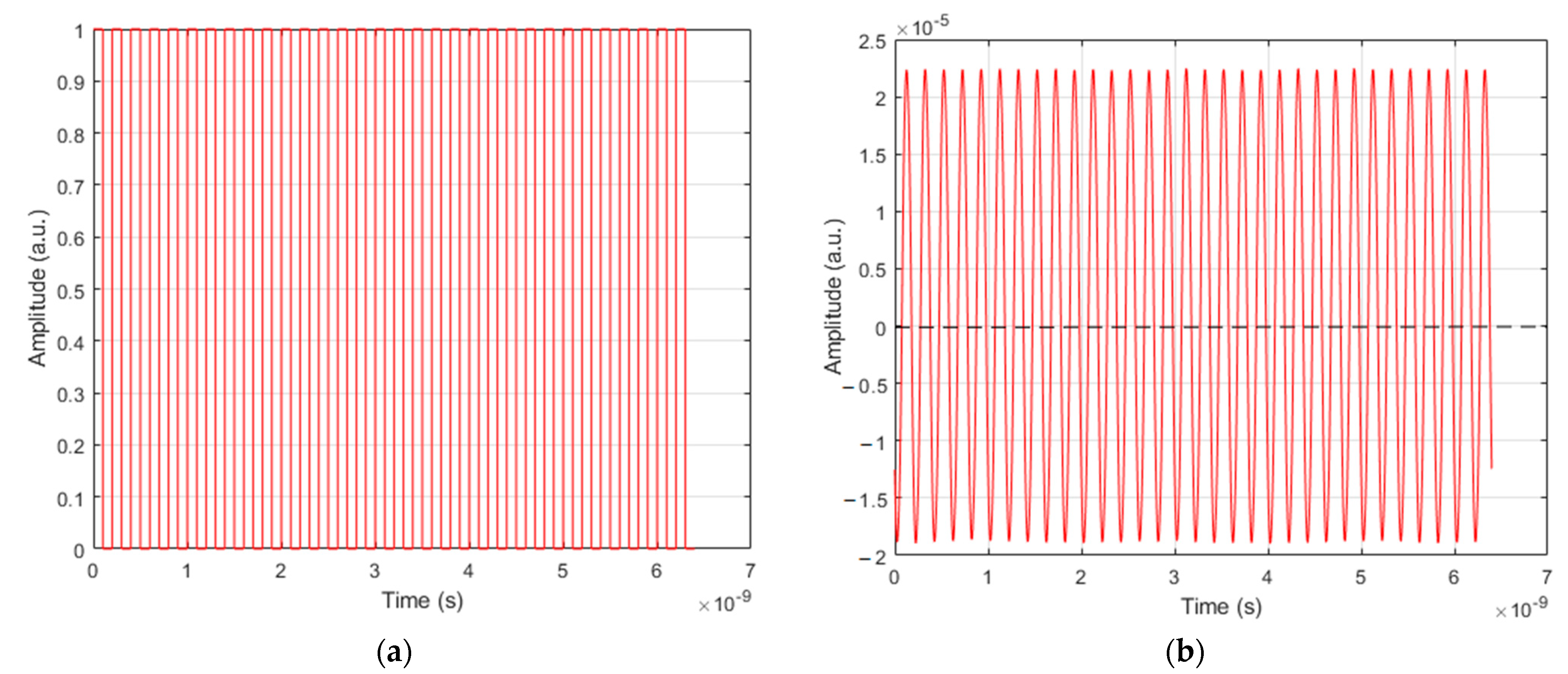
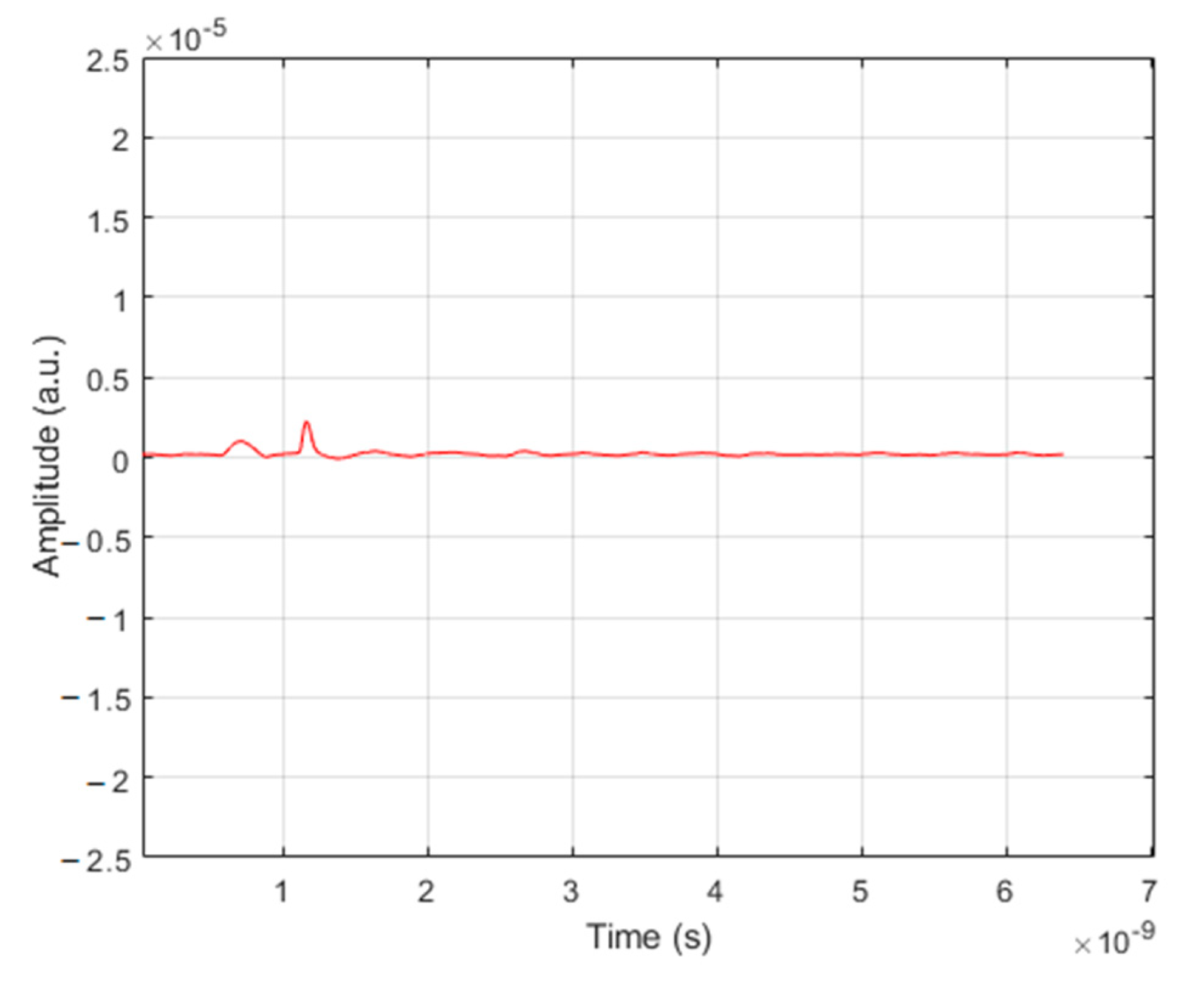
3.1. Feasibility of the Proposed Bi-OCDMA

The simulation was conducted using the well-known optical system software, OptiSystem version 10. Based on the architecture in Figure 1 and Figure 2, the first simulation was conducted with a single-user scheme to verify the feasibility of the proposed Bi-OCDMA scheme. The power of the CW laser array was set to 0 dBm to minimize the nonlinear effect, and one PRBS generator was used to generate the user’s information bit randomly with a sequence length of 512 bits and 8 samples per bit for transmission over the system.
Next, these information bits were fed to the PSK generator with a 0-degree phase offset and passed through the electrical bias and electrical gain for signal normalization before being used as a modulation signal. A phase modulator was utilized to modulate the information signals using the optical modulation signals. In addition, the coupling coefficients of all 2 × 2 couplers in the simulation were set to 0.5. A polarization splitter was used to split the signals into two orthogonal polarization states (0°and 90°, i.e., horizontal and vertical states). An optical adder was used in this simulation to combine the two optical signals. A polarization combiner was used to combine the two polarization states.
In this simulation, an FSO channel with a short-to-mid range was set as the transmission medium. An ideal circulator was used to direct the optical signal from one port to another and prevent the signal from propagating in an unintended direction. A uniform FBG was employed to reflect and transmit the wavelength based on the signature code. A photodiode was utilized as the detector for the received optical signals. A low-pass Bessel filter was used with a cut-off frequency of its linear phase response up to a bit rate of 0.75. An electrical subtractor was applied to subtract two electrical signal outputs to complete the bipolar scheme with balanced photodetection. A 3R regenerator was used to regenerate electrical signals. An optical spectrum analyzer was used to measure and investigate the optical spectra. An oscilloscope visualizer was used to monitor the output signals of the system. A BER analyzer was used to observe several parameters of the system performance, that is, BER and Q-factor. The overall parameters used in the simulations are listed in Table 2.
The modified M-sequence code with a code length of eight was used as the signature code. Based on Table 1, user#1 was assigned with the codeword X = [λ1H, λ2V, λ3H, λ4H, λ5H, λ6V, λ7V, λ8V] for user data bit of “0” and X ¯ = [λ1V, λ2H, λ3V, λ4V, λ5V, λ6H, λ7H, λ8H] for user data bit of “1.”
Figure 4 presents the measured spectra when bit “1” was transmitted after phase modulation and passing over the polarization splitter. Figure 4a illustrates the measured spectra at the upper side, λ1, λ3, λ4, λ5 measured at vertical polarization, and the light intensities were −3 dBm. Figure 4b shows the measured spectra at the lower side, λ2, λ6, λ7, λ8 measured at horizontal polarization, and the light intensities were −3 dBm.
Figure 5 depicts the measured spectra when bit “1” was transmitted after passing through the FSO channel. Figure 5a shows the encoded spectra for the horizontal polarization, λ2, λ6, λ7, λ8, which were measured with light intensities of −30 dBm. Figure 5b shows the encoded spectra for the vertical polarization λ1, λ3, λ4, λ5, which were measured with light intensities of −30 dBm. With an optical power of −3 dBm before passing through the FSO channel, the power was attenuated by approximately 27 dBm after transmission through the FSO channel due to the impact of atmospheric turbulence.
Figure 6 presents the measured spectra before the optical signals entered the upper and lower photodetectors when data bit “1” was sent. Figure 6a shows the total measured spectra at the upper branch, λ1, λ2, λ3, λ4, λ5, λ6, λ7, λ8, measured with light intensities of −30 dBm. Figure 6b presents the total measured spectra at the lower branch. No spectra were measured.
Using the same principle, when data bit “0” was sent, no spectral chip appeared at the upper branch, and eight spectral chips were measured at the lower branch, the electrical subtraction between the upper and lower branches resulted in negative signal amplitude, representing the negative parts “−1” of the bipolar scheme.
From Figure 6a,b, eight spectral chips appeared at the upper branch, and no spectral chip was observed at the lower branch; the electrical subtraction between the upper and lower branches resulted in positive signal amplitude, representing the positive parts “+1” of the bipolar scheme.
Further verification was undertaken by transmitting a series of user data bits alternating between bit “0” and “1.” Figure 7a,b illustrates the user’s information generated from PRBS, which generated a binary bit sequence between bit “0” and “1” with the corresponding received bipolar signals from the proposed Bi-OCDMA scheme, respectively.
The MAI cancelation features were evaluated using the mismatch scenario. The encoder used the user#1 signature code from the modified M-sequence, that is, 10111000, whereas the decoder was implemented with the user#2 signature code from the modified M-sequence, that is, 01110010, demonstrating the mismatch decoder. Figure 8 indicates the output spectra before photodetection when bit “0” was sent. Figure 8a shows the measured spectra at the upper branch, λ2, λ4, λ5, λ6, measured with light intensities of −30 dBm.
Figure 8b displays the measured spectra at the lower branch, λ1, λ3, λ7, λ8, and the light intensities were −30 dBm. In Figure 8a,b, four spectral chips appeared at the upper branch and four spectral chips were also measured at the lower branch, and the electrical subtraction between the upper and lower branches resulted in zero signal amplitude, proving the MAI elimination of the bipolar scheme. Figure 9 illustrates the output signals after balanced photodetection in the case of a mismatch decoder when bit “0” was sent. No signal was received by the user#2 decoder when the data bit was sent from the user#1 encoder, verifying the absence of the MAI effect on the other user. A small acceptable noise-floor signal was measured, resulting from the imperfect filter of the FBG decoder.
The simulation results proved the feasibility of the bipolar scheme from the proposed Bi-OCDMA with a phase modulator and verified the MAI elimination property of the system.

3.2. Performance of The Proposed Bi-OCDMA

A second simulation was conducted to test the proposed Bi-OCDMA under different channel conditions. The simulation was demonstrated using the architecture shown in Figure 3 with two simultaneous users. Some noise sources were implemented in the simulation to closely approximate the real environment of the FSO system. The noise sources included amplified spontaneous emission (ASE) noise, thermal noise, and shot noise with Gaussian distribution, where the total noise effect can be observed as:
σ t o t a l 2 = σ t h 2 + σ s h o t S 2 + σ s h o t A S E 2 + σ S A S E 2 + σ A S E A S E 2
Each noise induced in the simulation can be verified as follows:
  • Thermal noise:
σ t h 2 = 4 . k B . T R L . E N B
  • Shot-Signal Noise:
σ s h o t S 2 = 2 B e . ( r M 2 P S + i d )
  • Shot-ASE Noise:
σ s h o t A S E 2 = M 2 F .2 B e . q r P A S E
  • Signal-ASE Noise:
σ S A S E 2 = 4 B e . r 2 . M 2 . P S D A S E P s
  • ASE-ASE Beat Noise:
σ A S E A S E 2 = r 2 . M 2 . P S D A S E 2
where T is the absolute temperature of the device, R L denotes the receiver load resistance, k B is the Boltzmann constant, E N B is the receiver equivalent electrical noise bandwidth, B e denotes the equivalent noise bandwidth of the photodetector, r is the PIN responsivity, M is the gain, F denotes the excess noise factor, P s is the signal power, i d denotes the device dark current, q is the electron charge value, P A S E is the optical noise power, and P S D A S E denotes the power spectral density of the optical noise field (spontaneous emission).
Two channel conditions were implemented in the second simulation, namely, the AWGN channel and turbulence-induced fading channel. The AWGN channel was created by adding a white light source with a power of −130 dBm to the optical signals before transmission through the FSO channel. Furthermore, the gamma–gamma distribution was applied to model the turbulence-induced fading channel in this simulation.
In the gamma–gamma fading model, the probability of intensity I can be calculated as:
P ( I ) = 2 ( α β ) ( α + β ) / 2 Γ ( α ) Γ ( β ) I ( α + β ) / 2 1 K α β ( 2 α β I )
where Γ ( ) is the gamma function, and K α β ( ) is the modified Bessel function of the second kind 1 α and 1 β are the variances of the small- and large-scale eddies, and can be evaluated as follows:
α = exp [ 0.49 σ R 2 ( 1 + 1.11 σ R 12 / 5 ) 5 / 6 ] 1
β = exp [ 0.51 σ R 2 ( 1 + 0.69 σ R 12 / 5 ) 5 / 6 ] 1
where σ R 2 denotes the Rytov variance and is calculated from:
σ R 2 = 1.23 C n 2 k 7 / 6 z 11 / 6
where C n 2 is the parameter index refraction structure with a value varying from 10−13 m-2/3 for intense turbulence to 10−17 m−2/3 for weak turbulence, k is the optical wavenumber, and z is the parameter range.
First, a second simulation was conducted in the AWGN channel for extreme weather conditions based on the standard of propagation data required for the design of terrestrial free-space optical links from the International Telecommunication Union Radiocommunication Sector (ITU-R) P.1817 [38]. The attenuations under different weather conditions are shown in Table 3.
Four well-known SAC-OCDMA codes, that is, MD code, MQC code, modified M-sequence code, and Walsh–Hadamard code, were applied in the simulation. These four codes satisfy the correlation properties of Equations (5) and (6), revealing the compatibility to be implemented in the proposed Bi-OCDMA structure. The signature codes used in this simulation are listed in Table 4.
Figure 10 and Figure 11 show the performance of the proposed Bi-OCDMA system with four different codes under intense rainy and stormy weather conditions for the AWGN channel. The simulation results illustrate that the Walsh–Hadamard code achieved the best performance, followed by the modified M-sequence code, MQC code, and MD code. All codes had a higher impact in the stormy weather. Under intense rainy conditions, the modified M-sequence code exhibited the worst performance degradation with increasing FSO range, whereas in stormy conditions, the Walsh–Hadamard code suffered the worst performance deterioration. However, the Walsh–Hadamard code still achieved superior performance beyond a 500 m FSO range because this code had the best performance in the proposed Bi-OCDMA scheme. In stormy conditions, beyond 430 m, the modified M-sequence code worsened more than the MQC code, and beyond 500 m, it suffered the worst performance. The simulation results of the performance degradation for extreme weather conditions in the AWGN channel are displayed in Table 5.
In addition to the AWGN effects, the next simulation included turbulence-induced fading of the channel with medium turbulence conditions based on Equation (24). Simulations were also performed for extreme weather conditions, as shown in Table 3. Figure 12 and Figure 13 demonstrate the minimum log of BER and maximum Q-factor achieved by each code in intense rainy and stormy weather conditions for the AWGN and turbulence-induced fading channel.
The simulation results show that the Walsh–Hadamard code has superior performance, followed by the modified M-sequence code, MQC code, and MD code. The MD code still had the lowest performance deterioration compared to the other codes under these two weather conditions. The highest performance degradation under intense rainy conditions was suffered by the modified M-sequence code, whereas in stormy conditions, the Walsh–Hadamard code experienced the worst performance degradation even though it still achieved higher performance than the other codes, indicating that the Walsh–Hadamard code suffered great impact from optical signal attenuation in the stormy weather. Further, in stormy conditions, beyond 410 m, the modified M-sequence code became worse than the MQC code, and beyond 470 m showed the worst performance among the codes. The results of the performance degradation for extreme weather conditions in AWGN and turbulence-induced fading channel are shown in Table 6.
The final simulations tested the proposed Bi-OCDMA system under different turbulence conditions. Figure 14, Figure 15 and Figure 16 show the performance of different SAC codes implemented in the proposed Bi-OCDMA system under different turbulence conditions based on Equation (24).
The simulation results show that the Walsh–Hadamard code had the best performance, followed by the modified M-sequence code, MQC code, and MD code. In all turbulence conditions, the MD code achieved the lowest performance degradation with an increasing FSO range, revealing that the MD code can be applied for medium-distance FSO in the proposed Bi-OCDMA system. In the cases of weak and medium turbulence, the simulation results indicate that the modified M-sequence code suffered the worst performance deterioration with an increasing FSO range, whereas under intense turbulence conditions, the Walsh–Hadamard code achieved the worst performance degradation. These results showed that the Walsh–Hadamard code was the most affected by the turbulence condition, in addition to the increase in the FSO range. The simulation results of the performance degradation for different turbulence conditions are displayed in Table 7.

4. Conclusions

In this study, the feasibility of Bi-OCDMA with a phase modulator for polarization coding in short-to-medium range FSO environments was successfully implemented and validated. The simulation results showed that the proposed Bi-OCDMA could appropriately decode the original signal from its corresponding encoder. The proposed system was designed based on the original SAC-OCDMA technique, which theoretically relieves the MAI effect. Compared with the previous Bi-OCDMA scheme with an optical switch [21] and dual EOM [22], the proposed Bi-OCDMA scheme with a phase modulator improved the transmission rate and power efficiency. The performance measurements were simulated under extreme weather conditions, first for the AWGN channel, and second for the AWGN and turbulence-induced fading channels, by utilizing four different OCDMA codes. The proposed Bi-OCDMA system was further tested under different turbulence conditions. The simulation results revealed that the Walsh–Hadamard code had the best performance among the codes. The simulations also showed that in terms of the FSO range, the MD code was the most resistant to the increase in FSO distance, indicated by the lowest performance deterioration, whereas the modified M-sequence code suffered the highest performance degradation in almost all extreme weather and turbulence conditions. This result indicates that the MD code can be used for medium-range FSO applications in the proposed Bi-OCDMA system, whereas the modified M-sequence code can be applied to short-range FSO. In the case of stormy weather conditions and channels with intense turbulence, the Walsh–Hadamard code suffered the highest performance deterioration, although it still achieved superior performance, showing that Walsh–Hadamard code performance is most affected by optical signal attenuation caused by weather and turbulence conditions.
Future work can apply the proposed Bi-OCDMA technique in long-range wireless optical communication channels in correlation with different atmospheric conditions for higher multi-user schemes. Performance measurement with some parameters, such as BER, Q-factor, and the eye diagram, can be undertaken, including of the performance improvements resulting from several optimization techniques. Furthermore, Bi-OCDMA can be investigated for higher-order intensity modulation signals with different codes.

Author Contributions

Conceptualization, E.W. and C.-M.H.; methodology, E.W. and C.-M.H.; software, E.W.; validation, E.W. and C.-M.H.; formal analysis, E.W. and C.-M.H.; data curation, E.W.; writing—original draft preparation, E.W.; writing—review and editing, E.W. and C.-M.H. All authors have read and agreed to the published version of the manuscript.

Funding

This research was funded by the Ministry of Science and Technology, Taiwan (grant numbers MOST 108-2221-E-150-041 and MOST 107-2218-E-150-008-MY2).

Institutional Review Board Statement

Not applicable.

Informed Consent Statement

Not applicable.

Data Availability Statement

Data sharing not applicable.

Conflicts of Interest

The authors declare no conflict of interest.

References

  1. Liu, G.Y.; Jiang, D.J. 5G: Vision and Requirements for Mobile Communication System towards Year 2020. Chin. J. Eng. 2016, 1–8. [Google Scholar] [CrossRef] [Green Version]
  2. Sadiku, M.N.O.; Musa, S.M.; Nelatury, S.R. Free Space Optical Communications: An Overview. Eur. Sci. J. 2016, 12, 1857–7881. [Google Scholar] [CrossRef] [Green Version]
  3. Dat, P.T.; Kanno, A.; Inagaki, K.; Umezawa, T.; Yamamoto, N.; Kawanishi, T. Hybrid Optical Wireless-mmWave: Ultra High-Speed Indoor Communications for Beyond 5G. In Proceedings of the IEEE Conference on Computer Communications Workshops, Paris, France, 29 April–2 May 2019; pp. 1003–1004. [Google Scholar] [CrossRef]
  4. Nguyen, D.-N.; Bohata, J.; Spacil, J.; Dousek, D.; Komanec, M.; Zvanovec, S.; Ghassemlooy, Z.; Ortega, B. M-QAM Transmission over Hybrid Microwave Photonic Links at the K-band. Opt. Express 2019, 27, 33745–33756. [Google Scholar] [CrossRef] [PubMed]
  5. Chakkour, M.; Aghzout, O.; Chaoui, F. Theoretical Analysis of a Novel WDM Optical Long-Haul Network Using the Split-Step Fourier Method. Int. J. Opt. 2020, 1–9. [Google Scholar] [CrossRef]
  6. Singh, M.; Malhotra, J. A high-speed long-haul wavelength division multiplexing–based inter-satellite optical wireless communication link using spectral-efficient 2-D orthogonal modulation scheme. Int. J. Commun. Syst. 2019, 33, e4293. [Google Scholar] [CrossRef]
  7. Zhang, J.; Sharma, A.B. High-Speed Optical Time-Division Multiple-Access (OTDMA) Networks Using Optical Signal Processing. Photonic Netw. Commun. 1999, 1, 273–285. [Google Scholar] [CrossRef]
  8. Mishra, V.; Upadhyay, R.; Bhatt, U.; Kumar, A. DEC TDMA: A Delay Controlled and Energy Efficient Clustered TDMA Mechanism for FiWi Access Network. Optik 2020, 164921. [Google Scholar] [CrossRef]
  9. Rashidi, C.B.M.; Aljunid, S.A.; Ghani, F.; Fadhil, H.A.; Anuar, M.S. Phase Induced Intensity Noise Evasion in SAC-OCDMA Systems Using Flexible Cross Correlation (FCC) Code Algorithm. Aust. J. Basic Appl. Sci 2013, 7, 437–446. [Google Scholar]
  10. Mottaleb, S.A.A.; Fayed, H.; Aziz, A.; Aly, M. Enhanced Spectral Amplitude Coding OCDMA System Utilizing a Single Photodiode Detection. Appl. Sci. 2018, 8, 1861. [Google Scholar] [CrossRef] [Green Version]
  11. Aldhaibani, A.; Aljunid, S.A.; Anuar, M.S.; Abdullah, A.R.A.J. Increasing performance of SAC-OCDMA by combine OFDM technique. J. Theor. Appl. Inf. Technol. 2014, 66, 2005–2014. [Google Scholar]
  12. Zefreh, M.R.; Salehi, J.A. Theoretical Studies of Ultrashort Light Pulse Spectrally-Phase-Encoded OCDMA System Using Power-Cubic Optical Nonlinear Preprocessor. IEEE J. Light. Technol. 2015, 33, 5062–5072. [Google Scholar] [CrossRef]
  13. Al-Khafaji, H.M.R.; Aljunid, S.A.; Fadhil, H.A. Spectral efficiency analysis of bipolar spectral amplitude coding optical code-division multiple access systems using different one-dimensional codes. IET Optoelectron. 2012, 6, 215–222. [Google Scholar] [CrossRef]
  14. Park, S.J.; Kim, B.K.; Kim, B. An OCDMA Scheme to Reduce Multiple Access Interference and Enhance Performance for Optical Subscriber Access Networks. ETRI J. 2004, 26, 13–20. [Google Scholar] [CrossRef]
  15. Cha, M.; Yen, R.; Dimyati, K.; Abdullah, M. Using Bipolar Codes in Non-coherent Optical CDMA Systems to Stabilize Decision Threshold for BER Performance Improvement. J. Opt. Commun. 2006, 27, 324–328. [Google Scholar] [CrossRef]
  16. Al-Khafaji, H.; Ngah, R.; Aljunid, S.; Rahman, T. A new two-code keying scheme for SAC-OCDMA systems enabling bipolar encoding. J. Mod. Opt. 2015, 62, 327–335. [Google Scholar] [CrossRef]
  17. Patel, S.P.; Gupta, S. Novel Bipolar Reconfigurable Code for OCDMA Network. IJAERD 2018, 5, 493–500. [Google Scholar]
  18. Gupta, S.; Goel, A. New bipolar spectral amplitude code for cardinality enhancement in OCDMA network. J. Opt. 2020, 49, 1–8. [Google Scholar] [CrossRef]
  19. Bai, F.; Su, Y.W.; Sato, T. Performance Analysis of Polarization Modulated Direct Detection Optical CDMA Systems over Turbulent FSO Links Modeled by the Gamma-Gamma Distribution. Photonics 2015, 2, 139–155. [Google Scholar] [CrossRef] [Green Version]
  20. Chen, Z.-Y.; Yan, L.-S.; Pan, Y.; Jiang, L.; Yi, A.-L.; Pan, W.; Luo, B. Use of Polarization Freedom Beyond Gao, Z.; Wang, X.; Kataoka, N.; Wada, N. Rapid Reconfigurable OCDMA System Using Single-Phase Modulator for TimePolarization-Division Multiplexing to Support High-Speed and Spectral-Efficient Data Transmission. Light Sci. Appl. 2016, 6, e16207. [Google Scholar] [CrossRef] [Green Version]
  21. Cheng, H.C.; Wijanto, E.; Lien, T.-C.; Lai, P.-H.; Tseng, S.-P. Multiple Access Techniques for Bipolar Optical Code Division in Wireless Optical Communications. IEEE Access 2020, 8, 83511–83523. [Google Scholar] [CrossRef]
  22. Tseng, S.P.; Wijanto, E.; Lai, P.H.; Cheng, H.C. Bipolar Optical Code Division Multiple Access Techniques Using a Dual Electro-Optical Modulator Implemented in Free-Space Optics Communications. Sensors 2020, 20, 3583. [Google Scholar] [CrossRef] [PubMed]
  23. Gao, Z.; Wang, X.; Kataoka, N.; Wada, N. Rapid Reconfigurable OCDMA System Using Single-Phase Modulator for Time-Domain Spectral Phase Encoding/Decoding and DPSK Data Modulation. J. Lightwave Technol. 2011, 29, 348–354. [Google Scholar] [CrossRef]
  24. Aissaoui, A.; Hacini, L. Performance Comparison of Different SAC-OCDMA-FSO Detection Techniques in Presence of Atmospheric Losses. In Proceedings of the 6th International Conference on Image and Signal Processing and their Applications (ISPA), Mostaganem, Algeria, 24–25 November 2019; pp. 1–5. [Google Scholar] [CrossRef]
  25. Bhanja, U.; Panda, C. Performance Analysis of Hybrid SAC-OCDMA-OFDM Model over Free Space Optical Communication. CCF Trans. Netw. 2020, 3, 272–285. [Google Scholar] [CrossRef]
  26. Huang, J.F.; Yang, C.C.; Chiu, I.M. Hybrid MQC/M-Matrices Coding over Non-Coherent Spectral/Spatial Optical CDMA Networks. IJMOT 2006, 1, 592–595. [Google Scholar]
  27. Yen, C.T.; Chen, W. A Study of Bipolar Walsh-Hadamard Coding Method in Optical CDMA Networks. Appl. Mech. Mater. 2013, 284–287, 2667–2671. [Google Scholar] [CrossRef]
  28. Huang, J.F.; Yang, C.C.; Tseng, S.P. Complementary Walsh–Hadamard coded optical CDMA coder/decoders structured over arrayed-waveguide grating routers. Opt. Commun. 2004, 229, 241–248. [Google Scholar] [CrossRef]
  29. Yang, C.C.; Huang, J.F.; Tseng, S.P. Optical CDMA Network Codecs Structured with M-Sequence Codes over Waveguide-Grating Routers. IEEE Photon. Technol. Lett. 2004, 16, 641–643. [Google Scholar] [CrossRef]
  30. Rana, S.; Gupta, A. Performance of Different OCDMA Codes with FWM and XPM Nonlinear Effects. J. Opt. Commun. 2016, 38, 3. [Google Scholar] [CrossRef]
  31. Abd, T.; Aljunid, S.A.; Fadhil, H.A.; Ahmad, R.B.; Saad, M.N.M. Design and simulation a new code with zero cross-correlation for SAC-OCDMA networks. Aust. J. Basic Appl. Sci. 2012, 6, 112–119. [Google Scholar]
  32. Fayadh, R.; Wali, M.; Bonneya, M. Establishment Network by Using FSO Link Based on MD Code for Hybrid SCM-SAC-OCDMA Wireless System. Int. J. Electr. Comput. Eng. 2018, 8, 5107–5117. [Google Scholar] [CrossRef]
  33. Motealleh, M.; Mohsen, M. Simulation of a SAC-OCDMA 10 User ×15 Gb/s System Using MD Code. Int. J. Opt. Appl. 2014, 4, 20–26. [Google Scholar] [CrossRef]
  34. Yen, C.-T.; Cheng, H.-C.; Chang, Y.-T.; Chen, W.-B. Performance Analysis of Dual Unipolar/Bipolar Spectral Code in Optical CDMA Systems. J. Appl. Res. Technol. 2013, 11, 235–241. [Google Scholar] [CrossRef] [Green Version]
  35. Mrabet, H.; Mhatli, S.; Dayoub, I.; Giacoumidis, E. Performance Analysis of AO-OFDM-CDMA with Advanced 2D-Hybrid Coding for Amplifier-Free LR-PONs. IET Optoelectron. 2018, 12. [Google Scholar] [CrossRef]
  36. Dong-Nhat, N.; Elsherif, M.A.; Malekmohammadi, A. Investigations of High-Speed Optical Transmission Systems Employing Absolute Added Correlative Coding (AACC). Opt. Fiber Technol. 2016, 30, 23–31. [Google Scholar] [CrossRef]
  37. Avlonitis, N.; Yeatman, E.; Jones, M.; Hadjifotiou, A. Multilevel Amplitude Shift Keying in Dispersion Uncompensated Optical Systems. IET Optoelectron. 2006, 153, 101–108. [Google Scholar] [CrossRef] [Green Version]
  38. International Telecommunication Union. Propagation Data Required for the Design of Terrestrial Free-Space Optical Links; P Series Radiowave propagation; International Telecommunication Union: Geneva, Switzerland, 2012; p. 1817-1. [Google Scholar]
Figure 1. Proposed Bi-OCDMA encoder.
Applsci 11 05955 g001
Figure 2. Proposed Bi-OCDMA decoder.
Applsci 11 05955 g002
Figure 3. Proposed Bi-OCDMA architecture for two users.
Applsci 11 05955 g003
Figure 4. Encoded spectra after polarization splitting when bit “1” was transmitted: (a) vertical polarization at upper side; (b) horizontal polarization at the lower side.
Applsci 11 05955 g004
Figure 5. Output spectrum after transmission over FSO channel for user data bits of “1”: (a) horizontal polarization; (b) vertical polarization.
Applsci 11 05955 g005
Figure 6. Output spectrum before photodetection for user data bits of “1”: (a) total signals at the upper branch; (b) total signals at the lower branch.
Applsci 11 05955 g006
Figure 7. Input and output signals from the proposed bi-OCDMA system: (a) binary sequence generated from PRBS; (b) received bipolar signals.
Applsci 11 05955 g007
Figure 8. Output spectra before photodetection for the mismatch decoder when bit “0” was transmitted: (a) total signals at the upper branch; (b) total signals at the lower branch.
Applsci 11 05955 g008
Figure 9. Output signals of the proposed Bi-OCDMA system for mismatch decoder when bit “0” was transmitted.
Applsci 11 05955 g009
Figure 10. Performance of the system in intense rainy weather for the AWGN channel: (a) min. log of BER; (b) max. Q-factor.
Applsci 11 05955 g010
Figure 11. Performance of the system in stormy weather for the AWGN channel: (a) min. log of BER; (b) max. Q-factor.
Applsci 11 05955 g011
Figure 12. Performance of the system in intense rainy weather condition for AWGN and turbulence-induced fading channel: (a) min. log of BER; (b) max. Q-factor.
Applsci 11 05955 g012
Figure 13. Performance of the system in stormy weather condition for the AWGN and turbulence-induced fading channel: (a) min. log of BER; (b) max. Q-factor.
Applsci 11 05955 g013
Figure 14. Performance of the system under weak turbulence conditions: (a) min. log of BER; (b) max. Q-factor.
Applsci 11 05955 g014
Figure 15. Performance of the system under medium turbulence condition: (a) min. log of BER; (b) max. Q-factor.
Applsci 11 05955 g015
Figure 16. Performance of the system under intense turbulence condition: (a) min. log of BER; (b) max. Q-factor.
Applsci 11 05955 g016
Table 1. Modified M-sequence codes of length 8 with spectral-polarization coding.
User No.Signature SequenceData BitTransmitted Optical Polarized Signal
HV
#1101110000 λ1 λ3 λ4 λ5 λ2 λ6 λ7 λ8
1 λ2 λ6 λ7 λ8 λ1 λ3 λ4 λ5
#2011100100 λ2 λ3 λ4 λ7 λ1 λ5 λ6 λ8
1 λ1 λ5 λ6 λ8 λ2 λ3 λ4 λ7
#3111001000 λ1 λ2 λ3 λ6 λ4 λ5 λ7 λ8
1 λ4 λ5 λ7 λ8 λ1 λ2 λ3 λ6
#4110010100 λ1 λ2 λ5 λ7 λ3 λ4 λ6 λ8
1 λ3 λ4 λ6 λ8 λ1 λ2 λ5 λ7
#5100101100 λ1 λ4 λ6 λ7 λ2 λ3 λ5 λ8
1 λ2 λ3 λ5 λ8 λ1 λ4 λ6 λ7
#6001011100 λ3 λ5 λ6 λ7 λ1 λ2 λ4 λ8
1 λ1 λ2 λ4 λ8 λ3 λ5 λ6 λ7
#7010111000 λ2 λ4 λ5 λ6 λ1 λ3 λ7 λ8
1 λ1 λ3 λ7 λ8 λ2 λ4 λ5 λ6
Table 2. Simulation parameters.
ParameterValue
GlobalBit rate109 bits/s
Sample rate64.1010 Hz
Number of samples4096
Sensitivity−100 dBm
CW laserLinewidth10 MHz
Power 0 dBm
Azimuth45 deg
Noise threshold−100 dB
Frequency1546…1568 nm (λ1…λ12)
Electrical biasBias1
Electrical gainGain0.5
Phase modulatorPhase deviation180 degrees
FSO
channel
Range50–500 m
Transmitter aperture diameter5 cm
Receiver aperture diameter20 cm
Beam divergence2 mrad
Uniform FBGBandwidth125 GHz
Reflectivity0.99
Noise threshold−100 dB
Avalanche photodetectorGain3
Responsivity1 A/W
Ionization ratio0.9
Dark current10 nA
Sample rate32.1011 Hz
Thermal power density10−22 W/Hz
Table 3. International visibility code [38].
Weather ConditionsPrecipitationVisibility (m)Attenuation (dB/km)
Light fogStormy77018.3
Very light fogIntense rainy19006.9
Light mistAverage rain28004.6
Very light mistLight rain59002
Clean airDrizzle18,1000.6
Table 4. Signature codes for two users.
CodeSignature Code
MD [ 1 0 0 0 0 0 0 1 0 1 0 0 0 0 1 0 ]
MQC [ 1 0 0 0 1 0 0 1 0 0 0 1 0 1 0 0 0 1 0 0 1 0 0 1 ]
Modified M-Sequence [ 1 0 1 1 1 0 0 0 1 1 1 0 0 1 0 0 ]
Walsh-Hadamard [ 1 0 1 0 1 0 1 0 1 1 0 0 1 1 0 0 ]
Table 5. Performance degradation with the increasing of FSO range in the AWGN channel.
Weather
Condition
CodeMin. Log of BER (a.u.)Max. Q-Factor (a.u.)
Intense RainyMD1.94660.48296
MQC2.70310.63817
Modified M-Sequence3.90770.8524
Walsh-Hadamard3.27710.6095
StormyMD8.96612.48757
MQC9.04172.33693
Modified M-Sequence15.92624.0917
Walsh-Hadamard18.89684.07411
Table 6. Performance degradation with an increasing FSO range in the AWGN and turbulence-induced fading channel.
Weather
Condition
CodeMin. Log of BER (a.u.)Max. Q-Factor (a.u.)
Intense RainyMD2.57240.64368
MQC3.23820.76975
Modified M-Sequence5.13661.13579
Walsh-Hadamard4.81010.9055
StormyMD10.56383.02852
MQC10.66742.8358
Modified M-Sequence17.961094.80502
Walsh-Hadamard22.06084.96498
Table 7. Performance degradation with the increasing of FSO range in different turbulence conditions.
Weather
Condition
CodeMin. Log of BER (a.u.)Max. Q-Factor (a.u.)
Weak TurbulenceMD0.72850.17811
MQC1.50860.35096
Modified M-Sequence1.57460.3357
Walsh-Hadamard1.10050.2018
Medium TurbulenceMD1.00250.24587
MQC1.7670.41239
Modified M-Sequence2.11380.4531
Walsh-Hadamard1.83590.3382
Intense TurbulenceMD3.71430.94502
MQC4.08290.98137
Modified M-Sequence7.24071.6425
Walsh-Hadamard8.53791.6617
Publisher’s Note: MDPI stays neutral with regard to jurisdictional claims in published maps and institutional affiliations.

