Article

Design and Analysis of Cam Wave Generator Based on Free Deformation in Non-Working Area of the Flexspline

1
College of Mechanical Engineering, Donghua University, Shanghai 201620, China
2
State Key Laboratory of Mechanical Transmissions, Chongqing University, Chongqing 400030, China
*
Author to whom correspondence should be addressed.
Appl. Sci. 2021, 11(13), 6049; https://doi.org/10.3390/app11136049
Submission received: 27 May 2021 / Revised: 22 June 2021 / Accepted: 25 June 2021 / Published: 29 June 2021
(This article belongs to the Special Issue New Achievements in Structural Dynamics Analysis)

Abstract

:
Deformation stress of a flexspline under the action of a wave generator directly affects the service life of the flexspline and meshing quality of meshing pair. This study proposed a new deformation model for a flexspline, which incorporates forced deformation in the working area and free deformation in the non-working area, keeping the deformation shape unchanged during rotating. Based on this assumption of a deformation model, the mathematical model is further established, and the design approach of a cam wave generator is developed with the deflection curve of the ring structure. Then, a sample design with a double eccentric arc cam wave generator based on this deformation model is developed and analyzed in FEM. The results show that the deformation stress of the flexspline can be improved by relaxing the forced deformation in the non-working area, and the selected deformation shape can also remain unchanged during rotating. Moreover, the stress distribution and the maximum stress value could be improved with the variation of the combination coefficient, especially for the wrap angle.

1. Introduction

In recent years, gear systems have been developed rapidly with new calculation models [1], different materials [2] and new measurement methods [3]. In harmonic drive, a wave generator is used to make the flexspline produce controllable elastic deformation for realizing the transmission of motion and power. The flexspline is a thin-walled shell part, which is also the core part determining the performance of harmonic drive. The complex elastic deformation of the flexspline is generated with the combined action of the wave generator, the rigid wheel and the output shaft, but the basic deformation of the flexspline mainly depends on the type of the wave generator and its profile.
The working stress and the service life of the flexspline greatly determine the transmission performance of the whole harmonic reducer. In order to improve the meshing performance and extend the service life of harmonic gear transmission, scholars worldwide have studied the deformation and stress characteristics of the flexspline under the action of different types of wave generators. Bhabani [4] used the finite element method and experiments to compare and analyze the stress and strain of the flexspline in conventional cam wave generator and the split cam wave generator without assembling the ring gear. Han [5] studied the stress and related vibration characteristics of the flexspline with numerical analysis. Ostapski [6,7] presented the problem of failure of the elastic bearing supporting the generator in a harmonic drive and a solution to the problem of elastic deformation of thin-walled shell structures with complex shapes within the theory of geometrically non-linear shells. Vineet [8] proposed a method to calculate the load shared by the contact tooth pairs and the stress of the flexspline by estimating the contact load of multiple tooth pairs. Xin [9] simplified the profile of the gear tooth of the flexspline as two simple shapes, a rectangle and a trapezoid. The influence of gear tooth on the stresses in the flexspline has been studied and analyzed, and two simplified tooth profiles have been compared with each other. Fan [10] derived the deformation equation of the neutral layer of the flexspline in the engagement output harmonic drive and obtained the deformation relationship between the wave generator end and the engagement output end of the flexspline under the action of the wave generator based on the plate and shell theory. Zhang [11] analyzed the influence behavior of radial deformation on meshing performance in harmonic drive based on the envelopment meshing theory and obtained the stress distribution of the flexspline under the action of cam wave generator with finite element analysis. Hu [12] analyzed the internal stress distribution and stress sensitivity of the flexspline with multiple geometric structural parameters such as the aspect ratio of the cup, the wall thickness, the round corner radius and the width of the tooth ring in ANSYS software. Dong [13] studied the deformation problem of the flexspline in the harmonic reducer and analyzed the mathematical model of the flexspline’s neutral layer in theory. Yang [14] established a three-dimensional CAD model and a finite element model for the short barrel flexspline and studied the influence of geometric parameters on the stress value and distribution of the short barrel flexspline. Xia [15] proposed the problems of wear failure mechanism of flexible wheels and its future research direction of friction and wear mechanism. Routh [16] analyzed the coning phenomenon and the lubrication mechanism. Federico [17] mainly discussed the influence of wave generator shape on the relative motion between the fixed and flexible splines, and the relative motion of flexible spline viewed from fixed splines. Pacana [18] deals with the numerical stress calculation in the flexspline tooth rim of the harmonic drive. Ma [19] proposed an experimental method to investigate the effect of the driving speed on the deformation characteristics of the flexspline. Song [20] introduced a new type of harmonic drive—the harmonic chain drive. Yao [21] investigated the tooth effects on the bending stiffness coefficient and stress concentration factor in the tooth rim. Yang [22] investigated the effect of inhomogeneity of the load distribution on the surface of the gear teeth by using the partial axial-load index. Finally, for the first time, this paper establishes the profile equation of the rigid gear on the basic of differential geometry and theory.
Under the action of various wave generators, the deformation of flexspline mainly involves free deformation and forced deformation. For free deformation, the shape of the flexspline after deformation mainly depends on the equation of the elastic deformation curve. The shape of the flexspline in free deformation will change when the gear tooth is subjected to working load, which is a great weakness of free deformation. At this point, forced deformation can ensure the selected deformation shape and keep the deformation shape unchanged during rotating. However, for forced deformation, the shape of a cam wave generator with standard ellipse or cosine curve in common use is a great limit to the deformation optimization of the flexspline. In this paper, combining the advantages of free deformation and forced deformation in meshing quality and meshing stiffness, a new deformation model of the flexspline is proposed. The mathematical model and design method of the new wave generator are also established, and the profile of the cam wave generator is deduced by deflection curve in theory. Moreover, with a double eccentric arc wave generator taken as an example, a low stress cam wave generator is designed with this method. A comparative analysis on deformation stress of a flexspline is carried out to achieve better meshing stiffness with low basic deformation stress, which also verifies the feasibility and effectiveness of the new design model.

2. Background

In a harmonic drive with a cup-shaped flexspline, the flexspline is a cup-shaped thin-walled shell, the open end of which is built in the wave generator and the cup bottom of which is connected to the output shaft. With the rotational motion of the wave generator, the flexspline is forced to produce periodic basic deformation [6,10]. This deformation can realize the transfer between the outer teeth of the flexible wheel and the inner teeth of the rigid wheel near the major axis of the cam wave generator [16,23]. The shape of the wave generator is mainly to ensure that the teeth of the flexspline and the rigid wheel are well engaged in the major axis region, but completely disengaged in the minor axis region. On this basis, the number of meshing teeth need to be increased and the deformation stress needs to be reduced as much as possible for better meshing quality [8]. The basic deformation form of the flexible spline with the wave generator can be divided into two kinds. One is the free deformation, that is, the deformation of the flexible spline under the action of two or more concentrated radial forces. The other is the so-called forced deformation, that is, under the action of the cam wave generator, the same deformation with the contour of the cam wave generator would be generated [11]. This wave generator is also known as the “forced deformation wave generator”.

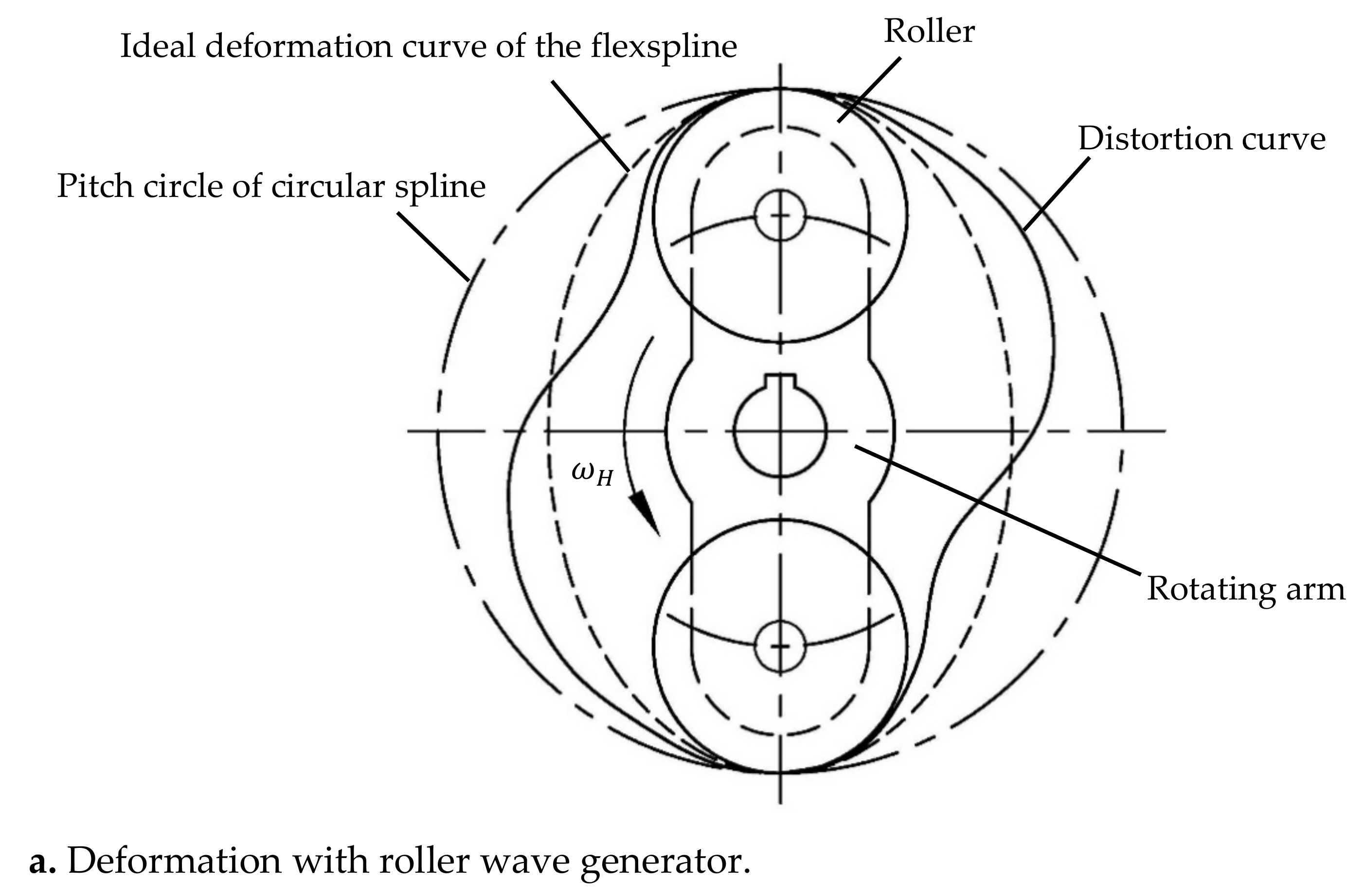
2.1. Free Deformation

There are two main types of wave generators that can make the flexspline produce free deformation: a roller wave generator and a double disc wave generator. In a roller wave generator, the small diameter of the roller causes great stress at contact points between the flexspline and the roller when the flexspline is driving. Moreover, because the wave generator is not fully supported, the actual deformation shape of the flexspline will deviate from the theoretical deformation shape and the deviation increases with the increase of the working load, even resulting in distortion of the flexspline deformation shape. The distortion curve and theoretical deformation curve of the flexspline’s neutral layer under the action of a double-roller wave generator are shown in Figure 1a [24]. In a double disc wave generator, the radius of the disk is much larger than the diameter of the roller, as shown in Figure 1b. Under the action of a double disc wave generator, the flexspline fits with the disc in the wrapping angle, and the stress of the flexspline at the contact point is reduced to avoid the distortion of the flexspline. However, the stiffness and bearing capacity of the flexspline are still insufficient because of the lack of the wave generator’s support in the non-working area.

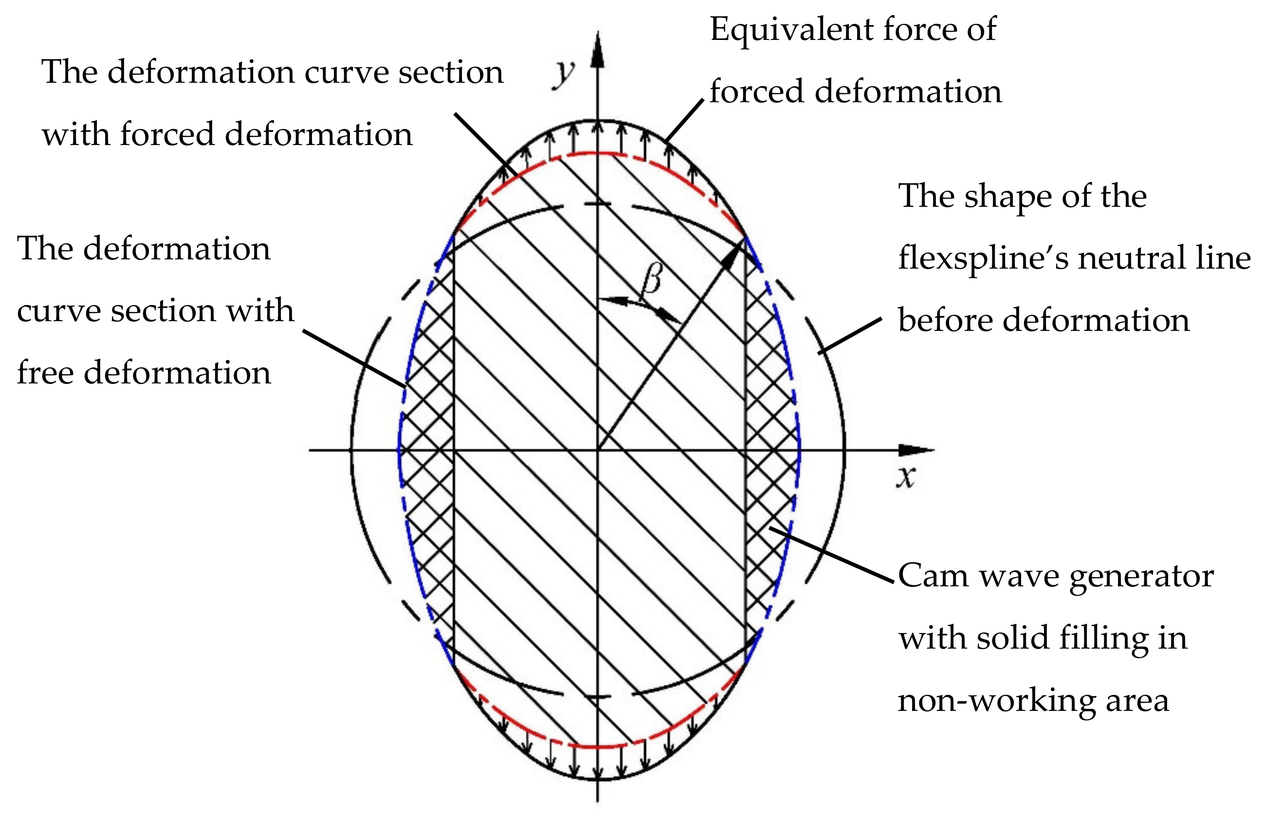
2.2. Forced Deformation

A cam wave generator is the main form to realize forced deformation of the flexspline, as shown in Figure 2. This kind of cam wave generator is designed and manufactured according to the deformation wave movement law of the flexspline. That is to say, the deformation curve of the flexspline’s neutral layer (curve 1 in Figure 2), known as the original curve, is the equidistant curve of the cam wave generator (curve 2 in Figure 2). This kind of cam wave generator makes the deformed flexspline and the wave generator maintain complete contact throughout the whole contour, so that the meshing reaches the ideal state. The harmonic drive with this cam wave generator can run smoothly and can gain high precision, which is especially suitable for high precision transmission [25].
In fact, free deformation or forced deformation mainly depend on the constraint of the deformed flexspline by the wave generator. The problem of distortion or insufficient stiffness is mainly due to the fact that only a few points or part of the flexspline are constrained by the wave generator after deformation. Forced deformation with all constraints not only solves the main problem of free deformation, but also ensures the selected deformation shape of the flexspline. Moreover, the deformation shape of the flexspline remains unchanged during rotating, which greatly improves the meshing quality.

3. Cam Wave Generators with Free Deformation in Non-Working Area

In theory, any deformation shape for a flexspline can be obtained based on forced deformation or free deformation. However, the selection of deformation shape is limited by the maximum radial deformation, the condition that the circumference of the constant velocity curve remains unchanged, and not allowing a change in the sign of the constant velocity curve’s curvature. In practice, the selection of the shape of wave generator should also consider the machining technology, stiffness, strength, etc.

3.1. Mathematical Model

The forced deformation in the non-working area of flexspline by the cam wave generator inevitably increases the basic deformation of the flexspline. In this study, a new deformation model of the flexspline is proposed for improving the basic deformation. The deformation model incorporates forced deformation in the working area and free deformation in the non-working area, and the deformation shape of the flexspline can also maintain unchanged during rotating by solid filling in the non-working area. The mathematic model of a cam wave generator based on this deformation model is shown in Figure 3. The contour shape of the cam wave generator in the working area can be selected to be any shape with maximum deformation w 0 , which mainly considered the meshing performance. The contour shape in the non-working area is an equidistant curve of the flexspline’s free deformation shape, which is under the action of a force equivalent to the selected shape of the working area. Under the action of this cam wave generator, the flexspline’s deformation not only can keep the advantages in the meshing performance just like with the forced deformed cam wave generator, but can also release the additional stress from the forced deformation in the non-working area. The solid filling in the non-working area can ensure the deformation shape of the flexspline in the process of rotating, so as to avoid the problem of distortion or insufficient stiffness.

3.2. Design of Cam Wave Generator

Because the wall thickness diameter ratio of the flexspline’s cup is relatively low, the force and deformation of the flexspline can be approximately treated as a thin-walled circular ring. Here, the circular ring is assumed to be deformed by a known convex curve in two symmetrical arcs, and the shape of the thin-walled circular ring after deformation is in a continuous fitting state with the convex curve, as shown in Figure 4a.
The forced deformation of the ring by a symmetric convex curve is equivalent to the continuous load p ( φ ) and q ( φ ) acting on the convex curve, while the non-load section of the ring deforms freely. Based on the symmetry of deformation, a quarter section of a convex curve is taken for analysis. The elastic deformation curve equation and the deflection curve of the ring u ( φ ) at this segment can be gained by solving the follow differential equation [26,27]:
d 5 u d φ 5 + 2 d 3 u d φ 3 + d u d φ = R 4 E I [ d p ( φ ) d φ + q ( φ ) ] ϕ = α , π 2
Here, the tangential load q ( φ ) and the radial load p ( φ ) are determined by the contour shape of the convex curve. u is the radial deformation at any point of the ring curve and R is the radius of the ring. E I is the bending stiffness of the ring.
When ϕ = 0 , α , the deformation curve of the ring is the same as that of the known convex curve and the equation of the convex curve in this section can be expressed:
ρ = ρ ( ϕ )
The radial deformation u corresponding to the convex curve section is expressed as:
u = ρ ( φ ) - R
According to the forced deformation of the convex curve segment and the deflection equation of the free deformation segment, the complete curve equation of the deformed ring can be obtained by:
ρ = ρ ( ϕ ) 0 < ϕ < α R + u ( ϕ ) α < ϕ < π 2
Here, point C is the dividing point between the non-working section and the working section, and α is the angle between O-x and OC.
So far, if the convex curve of the working section is determined, the complete deformation curve of the ring can be obtained by solving the deflection equation. The contour shape of the cam wave generator in the non-working area can be obtained by using the equidistant curve of the complete deformation curve of the ring.

3.3. Sample Design with Double Eccentric Arc Cam Wave Generator

A double eccentric arc is usually used for cam wave generator design, which mainly follows the basic idea of a double disc wave generator, but eliminating the additional force couple effect in the general double disc wave generator by setting up double arcs on both sides in one plane, as shown in Figure 4b. In the design of a double eccentric arc cam, if the flexspline’s deformation coincides exactly with the cam’s contour, the stress mutation will occur at the junction of the arc and the straight line, and the stress will be very large. If the flexspline is deformed only fitting the cam in the working section, there would still be free deformation in the non-working section, and the rigidity of the flexspline and the shape remaining during rotating are all problems. Based on the new deformation model, a double eccentric arc wave generator would be designed and optimized in this paper.
The convex curve of the double eccentric circular arc cam wave generator based on this deformation model is an eccentric circular arc curve. According to the thin-walled ring theory, the change of the ring shape caused by tangential load is consistent with that caused by radial load. The radial load is equal to the integral of the tangential load and the effect of the circumferential load q t is equivalent to that of the equivalent radial load q r t :
q r t = q t d φ
The total load on the outer ring is the sum of the equivalent radial load q r t and the radial load q r . Here, taking cosine deformation as an example, the tangential load of the equivalent load of circular arc shape’s forced deformation is set as q ( φ ) = 0 , and radial load is set as
p φ = A cos φ + B
According to Equation (1), the differential equation is
u = - A R 4 φ sin φ E I + C 1 + C 2 cos φ + C 3 φ sin φ + C 4 φ cos φ + C 5 sin φ
Here, C 1 ,   C 2 ,   C 3 , C 4 and C 5 are the undetermined coefficients of the general solution.
Due to symmetry of deformation, that is, u ( φ ) = u ( φ ) , the odd function in the general solution is omitted, and the deflection equation of the ring is simplified as
u = C 1 + C 2 cos φ + C 3 φ sin φ
According the known deformation elongation of the ring with φ = 0 , the rotation angle [26] of the ring at φ = π 2 is 0, and the total tangential displacement of the ring is zero with φ [ 0 , α ] . Then the constraint equation is developed as following:
α π 2 ( C 1 + C 2 cos ϕ + C 3 ϕ sin ϕ ) d ϕ + 0 δ ( r 2 + e 2 + 2 r e cos θ R ) d θ = 0 u ϕ = α = C 1 + C 2 cos α + C 3 α sin α = r 2 + e 2 + 2 r e cos δ R d u d ϕ ϕ = π 2 = ( C 2 sin ϕ + C 3 sin ϕ + C 3 ϕ cos ϕ ) ϕ = π 2 = 0
Then, the undetermined coefficients of C 1 , C 2 and C 3 can be gained by solving the Equation (9) as:
C 2 = C 3 = 0 δ ( r 2 + e 2 + 2 r e cos θ R ) d θ ( π 2 α ) ( r 2 + e 2 + 2 r e cos δ R ) 2 ( 1 sin α ) ( π 2 2 α ) cos α ( π 2 α ) α sin α C 1 = ( r 2 + e 2 + 2 r e cos δ R ) ( cos α + α sin α ) C 3
As shown in Figure 4b, the polar diameter ρ ( φ ) of the flexspline’s neutral layer after deformation in the working area is:
ρ ( φ ) = r 2 + e 2 + 2 r e cos θ
θ = ϕ r R
Here, r is radius of the arc, θ is the center angle of the arc and R is the radius of the neutral layer of the flexspline. Thus, the polar diameter ρ in this sample design can be obtained according to Equation (4).

4. Numerical Examples and Discussion

4.1. Parameter Selection

In order to verify the validity and effectiveness of the proposed model, some numerical examples are presented by the specific parameters. These examples cover standard ellipse, double eccentric arc, free deformation and forced deformation. The structure of the flexspline is shown in Figure 5. Table 1 and Table 2 show the detailed parameters of the flexspline and the wave generator. The model in this paper is simplified on the basis of the correct calculation: (1) The tooth wall thickness of the flexspline is simplified equivalently with 1.67 3 times of the original [28]. (2) The flexible bearing and the wave generator as a whole are assembled in the inner ring of the flexspline [29]. Hexahedron cells are used for the wave generator and tetrahedron cells are used for the flexspline. The shaft support constraint is applied to the inner hole of the flexspline, fixed constraints are applied to the bottom surface of the cladding plate and the rigid outer surface of wave generator is defined as the target surface. The friction coefficient between the flexspline and the wave generator is set as 0.1 and the stiffness coefficient is set as 0.1. In addition, the material parameters of the flexspline and wave generator in FEM are shown in Table 3.

4.2. Result Presentation

Figure 6, Figure 7 and Figure 8 show the equivalent stress of the flexspline’s tooth ring, which is at completed forced deformation ( β = 67.89 ° ) or at partial forced deformation in the working section in the double eccentric arc cam wave generator. The completed forced deformation is assumed under the next two conditions: (1) the neutral layer of the flexspline is the equidistant curve of the cam wave generator’s profile after deformation; (2) the flexspline fits the wave generator completely after deformation. The partial forced deformation in the working section is assumed that under the next two conditions: (1) the flexspline in the working section fits the wave generator after deformation; (2) the flexspline in the non-working section is completely in free deformation. As shown in Figure 6, the whole equivalent stress of the flexspline would increase obviously as the wrap angle becomes larger. With a fixed wrap angle, the equivalent stress value changed regularly from low at major axis to high at connected point and to a little high at the minor axis. Moreover, stress concentration may occur with improper parameter selection.
Figure 7 shows the equivalent stress on the outer end of the flexspline’s tooth ring. We can observe that the stress at the connected point would be too large to exceed the allowable stress and an excessive stress concentration would appear when the flexspline is in completed forced deformation by using the double eccentric arc cam wave generator with the wrap angle at 67.89°. Moreover, the equivalent stress at the minor axis is also too large for excessive deformation with excessive wrap angle. The main reason for this is the forced deformation of the flexspline in the non-working section by the cam wave generator. When we decrease the wrap angle gradually, the fitting area becomes less in the working area and a gap begins to appear in the non-working area between the flexspline and the wave generator; that is, the non-working section no longer fits together and begins to be in a state of free deformation, so the whole equivalent stress decreases rapidly. For the wrap angle from 67.89° to 50°, the maximum equivalent stress of flexspline is reduced from 2300 MPa to 510 MPa. With the wrap angle decreasing to 50°, the overall deformation stress of the flexspline is relatively moderate. This is mainly because decreasing the wrap angle results in the non-working area of the flexspline being in free deformation, which results in release of additional stress to further reduce the basic stress of the flexspline.
As shown in Figure 8, the deformation stress will reach the maximum at the major axis and repeat twice near the connected point of the wrap angle, and the variation range of the flexspline tooth ring’s equivalent stress decreases obviously with the reduction in wrap angle. For a smaller wrap angle, it can be notably found that the deformation stress distribution in the non-working area would be smoother with the same double eccentric arc in working section. The maximum value of the flexspline’s stress could be effectively improved with an appropriate wrap angle after the stress concentration is controlled. Moreover, with decreasing the wrap angle, the maximum value of the flexspline’s equivalent stress in the non-working area would be less. Thus, it can be concluded that the stress of the flexspline could be improved by releasing the forced deformation in the non-working area, and the wrap angle would be need to optimized for more reasonable stress distribution and smaller basic deformation stress value of the flexspline.
Figure 9 shows the equivalent stress on the whole structure of the flexspline under the action of the double eccentric arc cam wave generator, which is designed in the new deformation model with 30° in half wrap angle and solid filling in non-working area according the deflection curve. Maximum equivalent stress occurred at the round corner of the cup bottom with 385 MPa. Figure 10 shows the deformation equivalent stress at the outer end of the flexspline deformed by the double eccentric arc cam wave generator with gap or solid filling in the non-working area. The contour of the circular arc-curve wave generator is combined with two eccentric circular arcs and two corresponding reflection curves. In other words, the flexspline under the action of the circular arc-curve wave generator is fully supported by solid filling to the non-working area of the wave generator according to the deflection curve, but the non-working area of the flexspline under the action of the circular arc-line wave generator is not supported. It shows that the equivalent stresses of the flexspline on the two conditions agree with each other very well. The finite element analysis in this paper produced results essentially in agreement with references [7,17,30], and the stress curve is consistent with the research results of other scholars [4,11,12]. Therefore, the method of design of the cam based on the reflection curve in the non-working area is effective, and could gain lower deformation stress and keep the deformation shape of the flexspline unchanged during rotating.

5. Conclusions

In this paper, a new deformation model for improving the stress distribution and reducing the maximum value of the flexspline is proposed. In this deformation model, forced deformation remained in the working area for better meshing quality. For improving the deformation stress of the flexspline, the additional stress produced by the forced deformation in the non-working area was released. The deformation shape of the flexspline remained unchanged during rotating, which was realized by developing solid filling in the non-working area of the cam according to the deflection curve of the flexspline. The following conclusions could be made:
(1)
When the forced deformation in the non-working area is released, the stress distribution of the flexspline in working area is smoother, and the overall basic deformation stress of the flexspline is obviously reduced.
(2)
With increasing the wrap angle, the basic stress of the flexspline would also increase. Moreover, when the wrap angle increases to a certain value determined by cam parameters, the flexspline’s deflect causes stress concentration.
(3)
Solid filling in the non-working area of the cam according to the deflection curve of the flexspline is an effective method to keep the deformation shape of the flexspline unchanged during rotating, which ensures high meshing quality without increasing the basic stress.

Author Contributions

Conceptualization, S.W.; validation, D.L.; formal analysis, S.W.; investigation, S.M.; writing—original draft preparation, D.L. and S.M.; writing—review and editing, S.W. and D.L.; project administration, B.C.; funding acquisition, S.W. All authors have read and agreed to the published version of the manuscript.

Funding

This research is financially supported by National Nature Science Foundation of China (No. 51975115).

Institutional Review Board Statement

Not applicable.

Informed Consent Statement

Not applicable.

Data Availability Statement

The data presented in this study are available on request from the corresponding author.

Conflicts of Interest

The authors declare no conflict of interest. The funders had no role in the design of the study; in the collection, analyses, or interpretation of data; in the writing of the manuscript, or in the decision to publish the results.

References

  1. Hasl, C.; Liu, H.; Oster, P.; Tobie, T.; Stahl, K. Method for calculating the tooth root stress of plastic spur gears meshing with steel gears under consideration of deflection-induced load sharing. Mech. Mach. Theory 2017, 111, 152–163. [Google Scholar] [CrossRef]
  2. Zhou, Y.; Wu, Y.; Wang, L.; Tang, J. A new closed-form calculation of envelope surface for modeling face gears. Mech. Mach. Theory 2019, 137, 211–226. [Google Scholar] [CrossRef]
  3. Tang, J.; Yang, B.; Shi, Z. Influence on center distance by measurement force in double-flank gear rolling test. Measurement 2021, 168, 108321. [Google Scholar] [CrossRef]
  4. Bhabani, S.M.; Vineet, S.; Rathindranath, M. Effect of cam insertion on stresses in harmonic drive in industrial robotic joints. Procedia Comput. Sci. 2018, 133, 432–439. [Google Scholar] [CrossRef]
  5. Han, S.J.; Se, H.O. A study on stress and vibration analysis of a steel and hybrid flexspline for harmonic drive. Compos. Struct. 1999, 47, 827–833. [Google Scholar] [CrossRef]
  6. Ostapski, W. Analysis of the stress state in the harmonic drive generator-flexspline system in relation to selected structural parameters and manufacturing deviations. Bull. Pol. Acad. Sci. Tech. Sci. 2010, 58, 683–698. [Google Scholar] [CrossRef] [Green Version]
  7. Ostapski, W.; Mukha, I. Stress state analysis of harmonic drive elements by FEM. Bull. Pol. Acad. Sci. 2007, 55, 115–123. [Google Scholar]
  8. Sahoo, V.; Maiyi, R. Load sharing by tooth pairs in involute toothed harmonic drive with conventional wave generator cam. Meccanica 2018, 53, 373–394. [Google Scholar] [CrossRef]
  9. Xin, H.; Mo, H.; Gao, J.; Wang, W.; Cui, D.; Liu, L.; Wang, T.; Xin, Y. Study on the gear tooth influence coefficients of flexspline of harmonic drive. Adv. Mater. Res. 2013, 774–776, 144–147. [Google Scholar] [CrossRef]
  10. Fan, Y.; Wang, H. Study on the deformation of flexspline in the engagement out put harmonic drive. J. Nanjing Univ. Sci. Technol. Soc. Sci. Ed. 1996, 20, 38–42. [Google Scholar]
  11. Zhang, L.; Liu, X.; Wang, C.; Wei, L.; Qiao, X.; Wang, R. Influence of radial deformation on stress of flexspline and meshing characteristic of harmonic reducer. Mech. Transm. 2017, 41, 166–169. [Google Scholar] [CrossRef]
  12. Hu, S.; Yao, T.; Qin, H.; Zhang, Y.; Yang, B. Research of internal stress distribution of double arc flexspline. Mech. Transm. 2020, 44, 29–34. [Google Scholar] [CrossRef]
  13. Dong, H.; Wang, D. Elastic deformation characteristic of the flexspline in harmonic drive. In Proceedings of the ASME/IFTOMM, International Conference on Reconfigurable Mechanisms and Robots, London, UK, 22–24 July 2009; pp. 363–369. [Google Scholar]
  14. Yang, P. Harmonic Gear Driving Device and the Short Flexspline Study. Ph.D. Thesis, China Academy of Machinery Science and Technology, Beijing, China, 2006. [Google Scholar]
  15. Xia, T.; Jiang, P.; Ma, C.; Chen, W.; Yan, R. Research advance of the failure mechanism and friction wear of flexible wheel of harmonic reducer. J. Mech. Transm. 2016, 40, 173–176. [Google Scholar] [CrossRef]
  16. Routh, B.; Maiti, R.; Ray, A.K. Analysis of coning and lubrication at flexspline cup and cam interface in conventional harmonic drives. Ind. Lubr. Tribol. 2017, 69, 817–827. [Google Scholar] [CrossRef]
  17. Federico, G.; Victor, H.M.; Ettore, P. Influence of wave generator profile on the pure kinematic error and centrodes of harmonic drive. Mech. Mach. Theory 2016, 104, 100–117. [Google Scholar] [CrossRef]
  18. Pacana, J.; Witkowski, W.; Mucha, J. FEM analysis of stress distribution in the hermetic harmonic drive flexspline. Strength Mater. 2017, 49, 388–398. [Google Scholar] [CrossRef]
  19. Ma, D.; Wu, J.; Liu, T.; Yan, S. Deformation analysis of the flexspline of harmonic drive gears considering the driving speed effect using laser sensors. Sci. China 2017, 60, 1175–1187. [Google Scholar] [CrossRef]
  20. Song, G.; Chen, S. Study on the profile equation of the rigid gear of the harmonic chain drive. J. Mech. Transm. 2004, 28, 7–9. [Google Scholar] [CrossRef]
  21. Yao, Y.; Chen, X.; Xing, J. Tooth effects on assembling bending stress of flexible tooth rim in harmonic drive. Mech. Mach. Theory 2020, 150, 103871. [Google Scholar] [CrossRef]
  22. Yang, C.; Hu, Q.; Liu, Z.; Zhao, Y.; Cheng, Q.; Zhang, C. Analysis of the partial axial load of a very thin-walled spur-gear (flexspline) of a harmonic drive. Int. J. Precis. Eng. Manuf. 2020, 21. [Google Scholar] [CrossRef]
  23. Tang, T.; Jia, H.; Li, J.; Wang, J.; Zeng, X. Modeling of transmission compliance and hysteresis considering degradation in a harmonic drive. Appl. Sci. 2021, 11, 665. [Google Scholar] [CrossRef]
  24. Shen, Y.; Ye, Q. Theory and Design of Harmonic Gear Transmission; China Machine Press: Beijing, China, 1985. [Google Scholar]
  25. Li, F.; Li, X.; Guo, Y.; Shang, D. Analysis of contact mechanical characteristics of flexible parts in harmonic gear reducer. Shock Vib. 2021, 2021, 5521320. [Google Scholar] [CrossRef]
  26. Yang, S. Calculating the deformations and the internal forces of the ring and the wheel rim. J. Chengdu Univ. Nat. Sci. Ed. 1995, 2, 16–23. [Google Scholar]
  27. Bulte, C.H.F. The differential equation of the deflection curve. Int. J. Math. Educ. Sci. Technol. 1992, 23, 51–63. [Google Scholar] [CrossRef]
  28. Chen, X.; Liu, Y.; Xing, J.; Xu, W. Neutral line stretch of flexspline in harmonic driver. J. Mech. Eng. 2014, 50, 189–196. [Google Scholar] [CrossRef]
  29. Gao, H.; Li, Z.; Deng, Z. Sensitivity analysis of cup-shaped flexible gear parameters to its stress based on ANSYS. J. Mech. Eng. 2010, 46, 1–7. [Google Scholar] [CrossRef]
  30. Fu, J.; Dong, H.; Shen, Y. Stress analysis of the flexspline in harmonic gearing by using FEM. China Mech. Eng. 2007, 18, 2210–2214. [Google Scholar] [CrossRef]
Figure 1. Two typical types of wave generator with free deformation. Adapted from ref. [24].
Applsci 11 06049 g001aApplsci 11 06049 g001b
Figure 2. Forced deformation with cam wave generator. Adapted from ref. [24].
Applsci 11 06049 g002
Figure 3. New deformation model of the flexspline.
Applsci 11 06049 g003
Figure 4. Cam wave generator design in a new deformation model.
Applsci 11 06049 g004
Figure 5. Structure parameters of the flexspline.
Applsci 11 06049 g005
Figure 6. Equivalent stress of flexspline in double eccentric arc cam with different wrap angle.
Applsci 11 06049 g006
Figure 7. Equivalent stress with wrap angle from 67.89° to 30°.
Applsci 11 06049 g007
Figure 8. Equivalent stress with wrap angle from 30° to 40°.
Applsci 11 06049 g008
Figure 9. Equivalent stress of flexspline with improved cam wave generator.
Applsci 11 06049 g009
Figure 10. Comparative curve of equivalent stress.
Applsci 11 06049 g010
Table 1. The parameters of the flexspline.
ParametersSymbolsValues
Diameter of neutral line (mm) D m 41.98
Wall thickness (mm) h 0.26
Width of tooth ring (mm) b t 8
Width of cup (mm) b 23.5
Thickness of cup bottom (mm) h w 3
Outside diameter of cup bottom (mm) D 0 80
Table 2. The parameters of the wave generator.
ParametersSymbolsValues
Radius of the eccentric arc (mm) r 20.868
Eccentric distance (mm) e 0.39
The wrap angle (°) β 30~67.89
Table 3. The material parameters of the flexspline and wave generator in FEM.
Material ParametersWave GeneratorFlexspline
Steel type42CrMoSNCM439
Density7850 kg/m37870 kg/m3
Yield strength930 MPa835 MPa
Tensile strength1080 MPa980 MPa
Young’s modulus2.12 × 1011 Pa2.09 × 1011 Pa
Poisson’s ratio0.280.295
Publisher’s Note: MDPI stays neutral with regard to jurisdictional claims in published maps and institutional affiliations.

