Abstract
Atmospheric dispersion produces spectral elongation in images formed by land-based astronomical telescopes, and this elongation increases as the telescope points away from the zenith. Atmospheric Dispersion Correctors (ADCs) produce compensating dispersion that can be adjusted to best cancel out the atmospheric effect. These correctors are generally of two basic types: Rotating Atmospheric Dispersion Correctors (R-ADCs), and Linear Atmospheric Dispersion Correctors (L-ADCs). Lately, a third type, the “Compensating Lateral ADC” (CL-ADC) has been proposed. None of these design approaches allow for large corrector systems (with elements greater than 1 m in diameter), in which the secondary spectrum is corrected to small residuals, of the order of tens’ of milliarcseconds. This paper describes a new type of large corrector (>1 m diameter elements), which can achieve the correction of the secondary spectrum to the order of 10 milliarcseconds. This correction is achieved by combining the R-ADC and CL-ADC approaches to dispersion correction. Only glass types readily available in metre diameters are required.
1. Introduction
The Earth’s atmosphere imparts a prismatic effect on incident starlight, producing a spectral angular spread that increases with the tangent of the zenith angle at which the star is observed. At large zenith distances the effect can lead to several arc seconds elongation in the visible band. Figure 1 depicts atmospheric dispersion as a function of Zenith Distance in degrees.
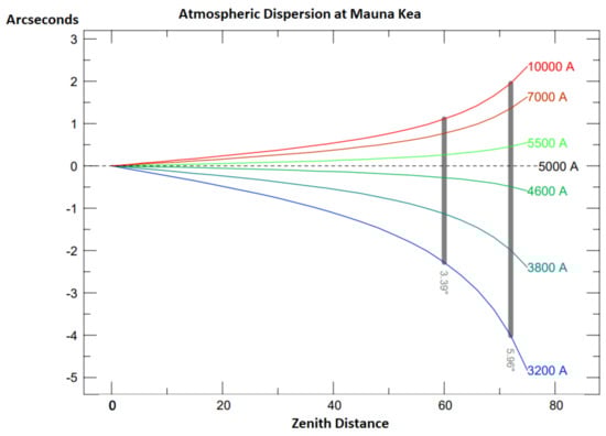
Figure 1.
Representative atmospheric dispersion, as a function of zenith distance in degrees, calculated for Keck at Mauna Kea. The indicated values from primary dispersion at 60 and 70 degrees zenith distance highlight the nonlinear nature of atmospheric dispersion, as the magnitude of primary dispersion almost doubles in the last 14% of the indicated zenith distance range.
Since Airy’s description [1,2] of difficulties arising from atmospheric dispersion during measurements of the transits of Venus and Mercury, astronomers have been investigating means of correcting it. Airy and his assistant Simms attempted to correct atmospheric dispersion by first introducing various prisms between the eyepiece and the eye, then later by arranging for the planar surface of the plano-convex field lens of a Ramsden eyepiece to be tilted by rotating the lens about the centre of curvature of its convex spherical surface. The resultant tilted plane surface introduced variable compensating dispersion and as the plane was at the telescope image, where marginal ray heights are zero, the tilted plane did not significantly degrade the telescope image.
In modern telescopes, spectrograph slits, fibres, and/or electronic detectors have replaced the eye. Additionally, the angular resolution of telescope images has improved to at least the seeing limit of excellent sites. In the case of telescopes incorporating adaptive optics systems, image quality has improved to near the theoretical diffraction limit imposed by the telescope aperture. There is also, in general, pressure to develop systems with increased bandwidth. The concomitant demand for improved correction of atmospheric dispersion correctors can be seen to have led to the development of three basic types.
The first type produces the desired tuneable dispersion in the “zenith-pointing” (zero parallactic angle) direction by counter-rotating pairs of Amici prisms. Each Amici prism has glasses selected to match in refractive index at a “stationary wavelength” but to have different dispersions. The prisms can be counter-rotated about the telescope’s optical axis so that their dispersion directions are aligned, giving a maximum dispersion, or counter-aligned, cancelling the dispersion. The former case is the setting when the telescope is at its maximum observing zenith-distance. The latter case occurs when the telescope points at zenith, and no correction is required. For intermediate pointing angles, the prisms are rotated in opposite directions by equal magnitudes through the range of 0 to ±90 degrees, with the bisector of the dispersion direction of the prisms kept parallel to the zenith direction. This arrangement provides a resultant dispersion in a fixed orientation matching the atmosphere and an adjustable magnitude. The prism’s angles are determined by the dispersion difference of the materials employed over the observed wavelength range. For the purposes of this discussion this type shall be referred to here as the “Rotating ADC” (R-ADC).
These systems introduce no monochromatic aberrations if used in collimated light, but if used in converging light, such as f8/-f/15 pencils commonly occurring at Cassegrain foci, or the faster convergence at prime focus, the plane surfaces of these prisms at normal incidence to the optical axis introduce spherical aberration and the tilted surfaces introduce asymmetric aberration.
Wilson [3] gives a comprehensive summary of the development of such correctors, in both collimated and in converging light, and describes the evolution of design of R-ADCs as they were used in shorter convergence of telescopes at Cassegrain and Prime Focus, which led to the incorporation of prismatic components in curved corrector elements. Wynne [4] and Epps [5] give some of the earliest published examples of such correcting R-ADCs for telescopes.
In general, the dispersions achieved with available glass pairs are not perfectly matched to the atmospheric dispersion, and so when wavelengths at the two extremes of the spectral range are corrected to the same angular deflection, intermediate wavelengths will have slightly different corrections. The maximum extent of this difference in correction is the secondary spectrum. Typically, this secondary spectrum is at least an order of magnitude less than the uncorrected atmospheric dispersion. Tighter requirements on the control of secondary spectrum naturally develop as telescope image quality improves. For adaptive optics systems, operating at or near the diffraction limit imposed by the telescope aperture, R-ADC types incorporating glasses or crystals with anomalous relative partial dispersion have been employed to reduce secondary spectrum to tens of milliarc seconds [6,7].
For large telescopes, working combinations of focal length and field can lead to systems requiring metre-class refracting elements. The relative paucity of available glass types at meter-plus diameters limits the ability to correct secondary spectrum with R-ADC type systems.
An alternative to the R-ADC is the Linear ADC (L-ADC). This design was initially developed for larger telescopes, specifically for the European Southern Observatory Very Large Telescope, and proposed by Beckers et al. [8]. In this design a single pair of prisms is produced and orientated such that, when the prisms are in contact, they form a plane parallel plate, centred on, and plane-perpendicular to, the optical axis. When in contact the prisms impart no dispersion. As the telescope’s observing angle increases in zenith distance, compensating dispersion is achieved by producing a separation of the prism elements along the optical axis direction.
L-ADCs have the advantage that only two elements of the same glass type are required to correct the primary lateral colour, so fused silica can be used. Fused silica is a robust material available in high optical homogeneity in large sizes. It also maintains excellent transmission to shorter wavelengths. Additionally, the required prism angles for the L-ADC are relatively shallow, so the prisms are not unduly thick or difficult to manufacture.
A serious problem with this sort of ADC is that the focal plane and pupil locations are modified as the prism is displaced. This complication renders the solution impractical for many applications. The inability of L-ADC systems to maintain image and pupil positions disqualifies such correctors from further consideration in this paper, though there is potential to produce image and pupil stabilized systems by combining more complicated motions and telescope active-optics, which will be the subject of future investigation.
A third type of ADC is one that displaces one or more optical elements incorporating curved surfaces in a direction perpendicular to the optical axis, and also rotates these elements about the local horizon axis. Wynne [9] first showed that by rotating a concentric meniscus lens, formed by two plano-spherical elements cemented together at the plane surfaces, about the meniscus surface centre of curvature, the plane internal surface of the meniscus could be tilted without introducing any other optical change to the system. If the two glass types making up the meniscus are selected to have matching refractive indices in some central colour, and different dispersions, such an element allows for the introduction of compensating dispersion about an undeviated central colour. In converging light, such elements can be incorporated in refracting field correctors, and aberrations introduced by the offset element can be to some degree compensated by the system. Wynne envisaged wide-field correctors incorporating such elements.
Saunders [10,11,12] et al. describe a variant on this idea, which they call the “Compensating Lateral ADC” (CL-ADC) in which one or more singlet elements of a corrector are displaced and rotated. The CL-ADC design has some interesting features for applications to large telescope correctors. Only one glass type is required and so correctors made entirely of fused silica are possible. With the inclusion of M2 compensation from the telescope, designs with stationary focal surface and pupils are possible. As will be seen in the following section, the secondary spectrum can be controlled favourably when compared to optimized alternatives of the R-ADC type.
In Section 2 below the “Correcting-ADC” (C-ADC) of the Giant Magellan Telescope (GMT) will be considered. Currently the telescope design baseline has a field corrector with a built-in R-ADC type component [13]. An alternative has been described (Ref. [10]), of the CL-ADC type. Particular attention will be paid to the secondary spectrum residuals of these two designs.
In Section 3 a consideration of the sign of the secondary spectrum residuals in the two designs considered in Section 2 leads to a new type of ADC that is nearly perfectly corrected for secondary spectrum. It will be shown that a corrector obtained by combining the first and third approaches described above (R-ADC and CL-ADC) achieves excellent correction of the secondary spectrum. The R-ADC component of the new corrector only requires optical glasses that are available at diameters of up to 1.5 m. Such a corrector will be shown to be an interesting candidate for future GLAO corrector designs.
2. Correcting ADCs for GMT Direct Gregorian Focus
The two-mirror design for the GMT (without corrector) is that of an aplanatic Gregorian telescope using seven-segmented primary and secondary mirrors (see Ref. [13]). The effective focal length for the telescope is 203 m (f/8.0) with the focus located 5.5 m below the primary mirror vertex. The focal length of 203 m means that the plate scale at the f/8 focus is 1 arcsecond per millimetre, to within 1.5%.
The aplanatic image is produced on a curved surface, and the dominant residual aberration is third-order astigmatism (the best focus is found at the surface lying half-way between the tangential and sagittal focal surfaces). The telescope can operate with or without a “pick-off” tertiary mirror (M3). In the “direct Gregorian mode” the M3 is retracted and an unvignetted field of ~26 arcminutes diameter is available, though astigmatism limits the seeing limited field (assuming best seeing of 0.25″) to about 10 arcminutes in diameter (see Figure 2).
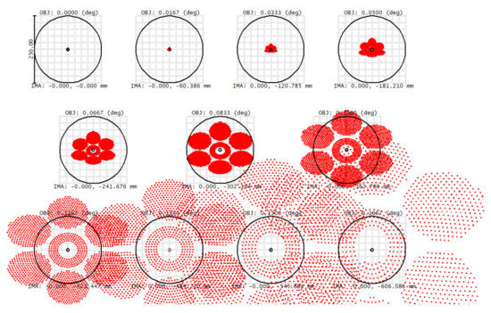
Figure 2.
Spot diagram for GMT in 1 arcminute radial field increments from on-axis to 10 arcminutes off axis. The circle size is 0.25 arcseconds. The increase in image size with field is almost purely quadratic, and due to third-order astigmatism. The seeing limit can be seen to be reached at a field radius of 0.08333 degrees, corresponding to the 10 arc-min field diameter described above.
For wider fields of view, a field corrector is required to ensure that the delivered image quality from the telescope does not degrade best seeing. For GMT’s wide-field mode a field-corrector incorporating an R-ADC type ADC is envisaged (Figure 3). The project refers to this as the “Correcting-ADC” or “C-ADC” subsystem.
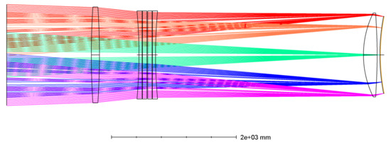
Figure 3.
Baseline “GMT Correcting-ADC” (C-ADC) corrector design, incorporating an Amici prism (R-ADC), as given in Figures 6–10 of Ref. [13]. The first element (far left) and last element (far right) are of fused silica. Element 1 is over 1.5 m diameter The Amici prism elements use optical glasses (see Table 6-3 and associated discussion on page 6–13 of Ref. [13]). In this paper “optical glasses” refers to glasses other than pure fused silica. Fused silica is of course a potential crown element for the Amici prisms but the performance in that case is not as good as can be achieved with other crowns.
As shown in Figure 4, the uncorrected lateral colour is reduced from approximately 3 mm (corresponding to 3 arcseconds) to about 0.35 mm, or 0.35 arcseconds.
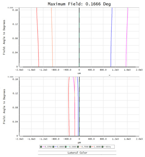
Figure 4.
(Top) Modelled atmospheric dispersion lateral at the GMT site in Chile for a zenith distance of 60 degrees. (Bottom) Residual secondary spectrum after C-ADC correction. The horizontal scale in microns is also very close to the exact value for the angular lateral colour in milliarcseconds.
Ref. [10] describes in detail a proposed alternative GMT C-ADC design of the CL-ADC type. Note that this CL-ADC design is a proposal that is not adopted by the project at this stage, and the R-ADC type design described in Ref. [13] is the baseline system for the GMT C-ADC. In the CL-ADC design, shown in Figure 5 below, the elements are all of fused silica. Lens elements 1 and 3 are decentred and tilted, and lens element 2 is tilted, to compensate atmospheric dispersion while maintaining image quality, and focal surface and pupil positions. M2 tilt and decentre are also included as degrees of freedom.
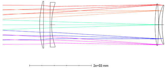
Figure 5.
All fused-silica CL-ADC design proposed as an alternative to the baseline C-ADC design for GMT by Saunders et al. Elements 1 to 4 are numbered from left to right.
Both corrector designs meet current GMT requirements for the C-ADC, and their relative merits are discussed in the references given.
3. The “Rotating Lateral” ADC (RoL-ADC)
For the purposes of this paper there is one key point to note from comparing Figure 6 and Figure 7. It is observed that the secondary spectrum residuals of the two optimized designs represented there are of opposite signs. Therefore, it follows that an approach combining lateral offset elements with counter-rotating Amici prisms should be capable of correcting the secondary spectrum. Such a design is produced by replacing element 2 of the CL-ADC design with the Amici prism pair of the baseline C-ADC design, and rebalancing by optimizing with an appropriate merit function. The resultant system has elements of fused silica as well as an Amici prism pair using the same Schott optical glasses as are indicated in Reference 13. Elements 1 and 4 are allowed to decentre and the M2 is decentred, tilted and allowed a small focus, as in the CL-ADC design.
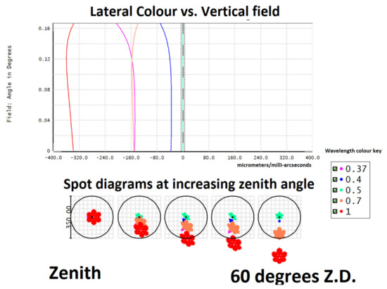
Figure 6.
(Top) Lateral colour vs. field plot for the R-ADC type GMT C-ADC baseline design for maximum (60 degree) zenith distance. (Bottom) Spot diagrams, showing the growth of the secondary spectrum residual with increasing zenith distance ranging from zero to 60 degrees. Spots are shown in 0.35 arcsecond circles. Wavelength values are in microns in this and all subsequent figures.
The results, given below in Figure 8, show that a significant reduction in secondary spectrum is indeed obtained. Reductions of the order of 8× in the secondary spectrum of the C-ADC baseline (R-ADC type) design of Figure 6, and 4× reduction in the secondary spectrum of the CL-ADC design of Figure 7, are achieved. The significance of this improvement is clear when we note that both the R-ADC-type baseline design and the CL-ADC design were each optimized to minimize the residual secondary spectrum, and so the results presented here for those systems represent the limits achievable in both cases.
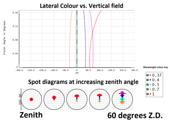
Figure 8.
(Top) Lateral colour vs. field plot for the RoL-ADC at maximum (60 degrees) zenith distance. The residual secondary spectrum is of the order of 40 milli arcseconds. (Bottom) The spot diagrams show the secondary spectrum is almost eliminated over the whole range of zenith distances.
Another point to note is that the new type of ADC, the “Rotating-Lateral ADC” or “RoL-ADC”, by combining actions that generate dispersion, can achieve its total correction with smaller magnitude motions, and/or simpler sets of, deflections than the CL-ADC design, and also with significantly smaller prism angles than is the case of the C-ADC baseline design. For example, in the CL-ADC design of Ref. [10], the largest lateral lens motion is 98 mm, whereas in the RoL-ADC design presented here the largest lateral lens motion is 30 mm. This compensates, to some degree, for the overall extra mechanical complexity required by the design.
4. Conclusions
This paper has investigated means of correcting secondary spectrum in meter-class correctors for large telescopes. The new type of corrector presented here is the only known type of meter-class corrector that is capable of simultaneously satisfying requirements of:
- Near-perfect secondary spectrum correction;
- Requiring only glasses that are readily available at large diameters;
- Near-zero deviation of image and pupil.
As with the old joke regarding optics fabrication, “good, cheap and on-time, pick any two…”, the currently known types of corrector described in the introduction are each only capable of simultaneously achieving two of these three goals.
The R-ADC types can achieve near perfect secondary spectrum correction with stable pupils and images, but require special glasses, or crystals, to achieve this performance. Such materials are not available for larger diameter correctors, such as the metre-class correctors that might be required for ELT-GLAO systems of the future. Residuals of the secondary spectrum using the available materials for a 1.5 m corrector of this type are shown in Figure 6.
In principle, the L-ADC types can achieve good secondary spectrum correction and can be made from glass types available in large diameters, but have the chronic problem of deviating image and pupil.
The CL-ADC systems are a relatively new concept, and improved designs for GLAO systems may well be possible, but the indications from the system considered in Section 2 are that residual secondary spectrum is not able to be controlled to the same degree as it is with the RoL-ADC system.
When we consider that modern GLAO systems are pushing boundaries both upwards in field size and downwards in wavelength [14], and also the general demand for increasing the bandwidth of observations, it seems likely that it will prove useful for optical designers of C-ADC systems in these cases to consider the benefits offered by the Rol-ADC, i.e., performance and material availability at large diameters, against the “costs” of additional mechanical complexity.
Funding
This research received no external funding.
Conflicts of Interest
The authors declare no conflict of interest.
References
- Airy, G.B. Note on Atmospheric Chromatic Dispersion as Affecting Telescopic Observations, and on the Mode of Correcting It. Mon. Not. R. Astron. Soc. 1869, 29, 333. [Google Scholar]
- Airy, G.B. On the Eye-piece for correction of Atmospheric Dispersion. Mon. Not. R. Astron. Soc. 1870, 30, 57. [Google Scholar] [CrossRef][Green Version]
- Wilson, R.N. Reflecting Telescope Optics I, 2nd ed.; Springer: Berlin/Heidelberg, Germany, 2004; pp. 392–401. [Google Scholar]
- Wynne, C.G.; Worswick, S.P. Atmospheric dispersion correctors at the cassegrain focus. Mon. Not. R. Astron. Soc. 1986, 220, 657–670. [Google Scholar] [CrossRef][Green Version]
- Epps, H.W.; Angel, J.R.P.; Andersen, E. Advanced wide-field broad-passband refracting field correctors for large telescopes. In International Astronomical Union Colloquium; Cambridge University Press: Cambridge, UK, 1984; Volume Number 79, pp. 519–548. [Google Scholar]
- Phillips, A.C.; Bauman, B.J.; Larkin, J.E.; Moore, A.M.; Niehaus, C.N.; Crampton, D.; Simard, L. The Infrared Imaging Spectrograph (IRIS) for TMT: The atmospheric dispersion corrector. In Ground-Based and Airborne Instrumentation for Astronomy III; International Society for Optics and Photonics: Bellingham, WA, USA, 2010; Volume 7735. [Google Scholar]
- Kopon, D.; Close, L.M.; Gasho, V. An advanced atmospheric dispersion corrector: The Magellan visible AO camera. In Adaptive Optics Systems; International Society for Optics and Photonics: Bellingham, WA, USA, 2008; Volume 7015. [Google Scholar]
- Avila, G.; Rupprecht, G.; Beckers, J.M. Atmospheric dispersion correction for the FORS focal reducers at the ESO VLT. In Proceedings of SPIE; International Society for Optics and Photonics: Bellingham, WA, USA, 1996; Volume 2871, pp. 1135–1143. [Google Scholar]
- Wynne, C.G. A new form of atmospheric dispersion corrector. Mon. Not. R. Astron. Soc. 1993, 262, 741–748. [Google Scholar] [CrossRef]
- Saunders, W.; Gillingham, P.; Lin, S.; Woodruff, B.; Rakich, A. An all-silica three-element wide-field corrector for GMT. In Ground-Based and Airborne Telescopes VI; International Society for Optics and Photonics: Bellingham, WA, USA, 2016; Volume 9906. [Google Scholar]
- Saunders, W.; Gillingham, P. Optical designs for the maunakea spectroscopic explorer telescope. In Ground-Based and Airborne Telescopes VI; International Society for Optics and Photonics: Bellingham, WA, USA, 2016; Volume 9906. [Google Scholar]
- Gillingham, P.R.; Cooke, J.; Glazebrook, K.; Mould, J.; Smith, R.M.; Steidel, C.C. A UV-visible prime focus camera for the Keck telescopes. In Advances in Optical Astronomical Instrumentation; International Society for Optics and Photonics: Bellingham, WA, USA, 2019; Volume 11203. [Google Scholar]
- GMTO. Website Open Resource. Available online: https://www.gmto.org/Resources/GMT-ID-01467-Chapter_6_Optics.pdf (accessed on 6 January 2021).
- Chun, M.R.; Carlberg, R.G.; Richer, H.B.; Mellier, Y.; Astier, P.; Lai, O.; Salmon, D.A.; Cuillandre, J.-C.; Andersen, D.; Pazder, J.; et al. Imaka: A one-degree high-resolution imager for the Canada-France-Hawaii Telescope. In Ground-Based and Airborne Instrumentation for Astronomy; International Society for Optics and Photonics: Bellingham, WA, USA, 2019; Volume 7735. [Google Scholar]


Publisher’s Note: MDPI stays neutral with regard to jurisdictional claims in published maps and institutional affiliations. |
© 2021 by the author. Licensee MDPI, Basel, Switzerland. This article is an open access article distributed under the terms and conditions of the Creative Commons Attribution (CC BY) license (https://creativecommons.org/licenses/by/4.0/).