1. Introduction
Anisotropy is a common structural feature of various systems formed in nature and beyond. The commonly accepted definition of anisotropy is different properties in different directions. For instance, in materials science, materials have different mechanical properties depending on the direction of their measurements [
1]. In seismic geology, the velocity of elastic waves depends on the direction of those waves’ propagation [
2]. In addition, “morphogenesis in plants depends critically on directional (anisotropic) growth” [
3].
We will consider anisotropic features of layered systems, which are to some extent different from the broadly used definitions of isotropy and anisotropy. The patterns found in fish scales are one example of a layered growth system that has an anisotropy of structure. The incremental growth of fish scales results in the formation of layers across a 2-D plane. One growth layer describes a cycle of fish scale growth at an instance of time ti, and the thickness of the layer is the measure of the growth rate at ti. These layers are distinguished by numerous breaks and confluences due to the fact that the growth rate of fish scales varies in different directions. That is, the growth layers exhibit an anisotropic structure due to the anisotropic growth of the fish scales.
Cross sections of lamellar bones, corals, and trees similarly exhibit patterns of anisotropic growth layers formed by living systems where a layer is formed at an instant of time t
i. Layered anisotropic structures can be found in both natural patterns and manmade objects, including satellite images of the surface of Mars, the human aorta, alloys, and many others [
4], even though their layered structures were formed differently than those of the growth layers found in living systems.
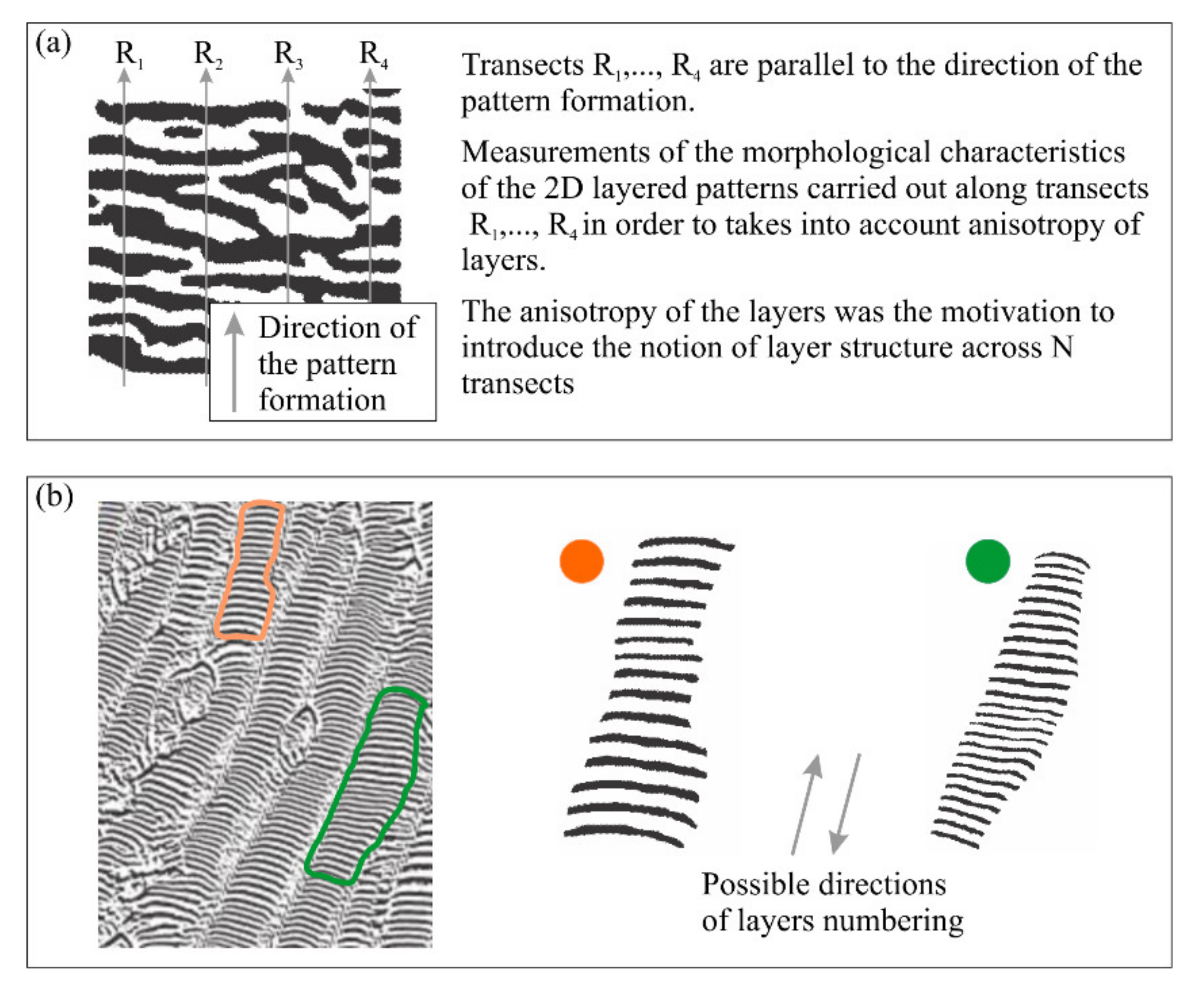
The anisotropy of the physical, mechanical, or electrical properties of an object under study implies that the property’s measurements are carried out along N transects in N different directions. The anisotropy of a structure made up of layered patterns implies that measurements are carried out along N parallel transects, which are oriented in one direction only (
Figure 1a). If the layers represent growth increments, then the direction of the numbered layers coincides with the direction of pattern formation. Thus, the set of transects R
1, …, R
j, …, R
N represents the coordinate system used for the measurement of patterns with anisotropic characteristics. A layered pattern with an isotropic structure implies that there are no breaks and confluences in the structure of the layers (
Figure 1b).
An empirical model (EM) of 2-D layered patterns was proposed with the aim of providing a tool to quantify the morphological features of anisotropic layered objects [
6,
7]. The EM has three components: an N-partite graph G(N), a Boolean function (BF) to describe the 2-D structure of the layers, and table T
M,N, which comprises the thickness of the layers along transects R
1, …, R
N; EM = {BF, G(N), T
M,N}. Transects R
1, …, R
N that are used for the construction of the EM are straight lines that are always distributed evenly across a 2-D layered pattern and are perpendicular to the direction of pattern formation or numbering of layers.
The N-partite graph G(N) consists of a sequence of bipartite graphs, G(R1, R2), …, G(Rj−1, Rj), …, G(RN−1, RN), where G(Rj−1, Rj) is a bipartite graph that describes the structure of a layered pattern situated between nearby transects Rj−1 and Rj. An isotropic layer here would imply that the vertex a∈Rj−1 connects only with the vertex b∈Rj, and b∈Rj connects only with a∈Rj−1. The edge ab in G(Rj−1, Rj) is therefore an isotropic edge, and the vertices a and b are also isotropic. This means that the isotropic edges and vertices form a defined layer that has no confluences and breaks in its structure.
The layers located between R
j−1 and R
j that exhibit breaks and confluences (
Figure 2) are considered anisotropic layers, or anisotropic edges and vertices in terms of G(N).
Figure 2a shows a layered anisotropic pattern crossed by five transects. The corresponding five-partite graph (G(5)) is shown in
Figure 2b. Graph G(5) is composed of bipartite graphs G(R
1, R
2), G(R
2, R
3), G(R
3, R
4), and G(R
4, R
5). The isotropic edges and vertices (shown in blue) and the anisotropic edges and vertices (shown in red) for bipartite graphs G(R
j−1, R
j) are presented in
Figure 2c.
The parameter of the amount of disorder in the layer structure (DStr) was introduced to describe the deviation of an anisotropic pattern from its isotropic analog [
4]. DStr is proportional to the number of anisotropic vertices and edges. If DStr = 0, then the pattern consists of layers without breaks and confluences. This means that the pattern consists of only isotropic layers (
Figure 1b). A DStr of zero thus indicates the highest level of order in a layered pattern and a DStr of 1 indicates the highest level of disorder in the structure of a layered pattern, i.e., G(N) is only comprised of anisotropic layers. It is necessary to specify that special point patterns [
8] are beyond the scope of the present work.
There are an infinite number of both natural and manmade patterns which visually do not consist of layers.
Figure 3 shows patterns of various categories, including those found in nature (
Figure 3a), medicine (
Figure 3b), the geosciences (
Figure 3c), materials (
Figure 3d,e), and art (
Figure 3f). We call such categories of patterns arbitrary. In this paper, we focus on binary arbitrary patterns and grayscale patterns with a high level of edge gradient. Such a focus allows us to use a relatively simple procedure to convert these patterns into a binary format.
The present paper continues our previous work [
4,
6,
7]. The title of this paper states our goal: to justify that binary arbitrary patterns and layered patterns, both natural and manmade, are composed of isotropic (IL) and anisotropic (AL) layers. To reach this goal, this paper will do the following:
show that AL and IL are the building blocks of binary arbitrary patterns (meaning that the EM could be used to formalize the morphological properties of arbitrary patterns);
illustrate the possibility of reconstructing the original arbitrary pattern from its EM; and
introduce three parameters for layers: disorder of layer size (DSize), pattern complexity (PCom), and disorder of layer structure (DStr).
Figure 3.
Examples of arbitrary patterns. (
a) Mars’ surface; Credit: NASA [
9]. (
b) Melanoma; Credit: Wikipedia [
10]. (
c) Contour map; Credit: [
11]. (
d) Microstructure of graphene; Credit: [
12]. (
e) Microstructure of bronze: Credit: Wikipedia [
13]. (
f) Artwork; Credit. Wikipedia. Hokusai [
14].
We justify the usefulness of our proposed metric by showing that the DStr, DSize, and PCom parameters can be used to quantify the morphology of binary patterns, reveal changes in these patterns’ size and structure, and act as shape characteristics. Our proposed method can be applied to both arbitrary patterns, and convex and concave polygons of any configuration, even if the pattern or polygon consists of straight lines alone.
Anisotropic and isotropic layers serve as informational units for describing the morphology of layered and arbitrary patterns. These informational units substantially differ from that of pixels, which is used in methods that are based on Shannon entropy [
15]. Another distinctive feature of the proposed method is the presence of the reference pattern, which is comprised of layers that have an isotropic size and structure. The parameters DStr, DSize, and PCom are calculated based on this reference pattern. This means that:
The DStr serves as the measure of deviation from an isotropic analog in patterns with an anisotropic layer structure;
The DSize serves as a measure of deviation from an isotropic analog in patterns that have an anisotropic layer size; and
The PCom serves as a measure of deviation from an isotropic analog in patterns with both an anisotropic layer size and structure.
The paper is organized as follows. In the Materials and Methods section, we justify that the EM could be used for quantifying the morphological characteristics of arbitrary patterns by comparing visual macro differences and non-visual micro similarities between layered and arbitrary patterns. We also illustrate that a binary pattern could be reconstructed from the EM. The parameters DSize and PCom are presented to describe the morphological characteristics of binary patterns. The outcome of experiments that are designed to showcase the effectiveness of the DStr, DSize, and PCom parameters are presented in the Results section. The Discussion section contains comparisons of our proposed method with several existing ones; descriptions of the assumptions, limitations, and pros and cons of our proposed method; and areas of potential application and future work.
2. Materials and Methods
2.1. Layered vs. Arbitrary Patterns: Micro-Similarities and Macro-Differences
For the sake of simplicity and without loss of generality, we assume that arbitrary binary patterns consist of lines of equal thickness. The first visual impression of layered patterns (
Figure 1) is that the layer serves as a basic macro structural element for different categories of layered patterns. This means that the layer is the dominant structural characteristic of various categories of layered patterns. The first visual impression of arbitrary patterns (
Figure 3) is that they do not exhibit layers as their dominant morphological characteristic, since arbitrary patterns consist of many different categories of micro- and macro-structural elements. This is the reason why these patterns are considered arbitrary.
Figure 4 summarizes the visual differences and similarities of layered and arbitrary patterns. Layers are the dominant feature of the entire area of layered patterns, which can easily be recognized by the naked eye. Patterns of fish scales and the surface of Mars are typical examples of layered anisotropic patterns. The structure of these patterns is essentially different from those of arbitrary patterns such as labyrinth and Turing patterns (
Figure 4a). Layers are not the dominant features of labyrinth and Turing patterns on a global scale. On a local (micro) scale, these patterns are comprised of layers in the same way as the patterns of fish scales and Mars’ surface are (
Figure 4b).
The naked eye is not a suitable tool to explore the micro-features of patterns. Thus, a magnifying glass was used for this purpose. Two nearby transects, R
j−1 and R
j, played the role of the magnifying glass, since they allowed us to explore a very narrow area of a 2-D arbitrary pattern.
Figure 4b shows fragments of the arbitrary pattern structure situated between R
j−1 and R
j. It is apparent that graphs G(R
j−1, R
j) of labyrinth and Turing patterns consist of IL and AL. This means that:
Statement (1) is also true for all bipartite graphs G(R
1, R
2), …, G(R
N−1, R
N) that show labyrinth and Turing patterns (
Figure 4b). Thus,
AL and IL are the building blocks of layered as well as arbitrary binary patterns, according to Statements (1) and (2). Thus, the EM of layered patterns could potentially serve as a tool for quantifying the morphological characteristics of arbitrary graphical systems.
2.2. Reconstruction of Binary Patterns from the Empirical Model
The goal of this section is to estimate how much the EM reliably describes a binary arbitrary pattern. To reach this goal, the original arbitrary pattern was converted into the EM, then reconstructed from the EM [
19]. The patterns before and after this reconstruction were then compared.
A binary pattern situated between R
j−1, R
j consisted of black and white pixels. The black pixels formed a configuration of the pattern under study. The white pixels were used to construct G(N) There is a one-to-one correspondence between G(N) and the set of black pixels situated between R
j−1 and R
j. This means that if the colors are inverted, then G(R
j−1, R
j) is converted into the pattern under study, and the pattern under study will be converted into G(R
j−1, R
j). This feature of binary patterns was used to formalize the construction of G(N), and to measure the thickness and area of the layers [
5,
6]. The outputs of procedures for developing the EM are the following data sets:
The number of transects and their direction and position in the 2-D plane.
The coordinates of graph vertices situated along Rj, j = 1, N.
The adjacency matrix that describes the connectivity between graph vertices situated along Rj−1 and Rj, j = 1, N.
The coordinates of points where the black pixels of the forming front and R
j intersect (
Figure 5a). V
j denotes the set of points, i.e., vertices v
1, j, v
2, j, …, v
p, j, of the intersection of the forming front and R
j.
Figure 5a shows the point of intersection of the forming front with transect R. A fragment of the pattern is presented in
Figure 5a in the Comma Separate Values (CSV) file, where 1 represents black pixels.
The adjacency matrix (AM-P) describes the connectivity between V
j−1 and V
j (
Figure 5b). The AM-P describes the structure of the pattern under study.
To reconstruct the pattern between R
j−1 and R
j, we construct a bipartite graph based on V
j−1, V
j and the AM-P. The limitation of using the AM-P for pattern reconstruction lies in the fact that the AM-P contains no information about the configuration of edges between sets of vertices V
j−1 and V
j, nor does it contain information about the thickness of these edges. Thus, straight lines of identical thicknesses comprise the layers between nearby transects.
Figure 5b shows the pattern before and after reconstruction and the corresponding AM-P. The accuracy of such pattern reconstruction increases as the distance between the transects decreases.
The text pattern rendered in raster binary format is used as the test sample to illustrate the text’s geometry before and after reconstruction (
Figure 6a). The post-reconstruction text is readable but visually looks more complicated than the pre-reconstruction text because it has many structural irregularities. Charts DStr = f(number of transects) demonstrates (
Figure 6b) two apparent facts in quantitative terms:
DStr (after reconstruction) > DStr (before reconstruction),
The differences between DStr (after reconstruction) and DStr (before reconstruction) nonlinearly increase as the number of transects goes up.
Thus, the parameter DStr could be applied to set up the correspondence between the number of transects used for the construction of the EM and the how well the EM compares to the pattern being studied. In other words, the DStr could potentially serve as the measure of how accurately the EM corresponds to the structure of the pattern being studied. For instance, the difference between the DStr of the text before and after reconstruction is equal to 0.637–0.617 = 0.020 = 2.0% (
Figure 6b). Thus, parameter DStr could be applied to set up correspondence between number of transects used for the construction of the EM and the level of adequacy of the EM to a pattern under study.
2.3. Disorder of Layer Structure (DStr)
The isotropic and anisotropic vertices of G(N) are used to calculate the DStr of arbitrary patterns because it allows us to take into account an isolated vertex which is not the endpoint of any edge, for instance vertex A
4 in
Figure 5b. Let us denote VAns(j−1, j) an anisotropic vertices in the bipartite graph G(j−1,j) and VAll(j−1,j) will denote all vertices comprising G(j−1,j). The
of G(j−1,j) is
DStr[G(j−1,j)] is the measure of deviation of the bipartite graph G(j−1,j) from a graph comprised of isotropic vertices alone. In terms of a pattern, this means that DStr[G(j−1,j)] is the measure of the deviation of an arbitrary pattern situated between Rj−1 and Rj from an isotropic pattern. The disorder of layer structure of N-partite graph G(N) is
The value of DStr[G(1, N)] depends on the sampling density (i.e., the number of transects used to calculate DStr[G(1,N)]). This leads to the question of how many transects should be used to quantify DStr[G(1, N)], which has not yet been technically defined.
Because the anisotropic components of a layered pattern are unevenly distributed in 2D space, we examine multiple versions of the sampling density to determine how many transects are necessary to quantify DStr. The general principle in choosing the number of transects is based on the fact that we do not know a priori how many transects will best describe the particular layered pattern. In these circumstances, our method is to examine many different versions of transect sets. In the present work, all transects are straight lines, and the distance between two adjacent transects remains constant across all transects.
The minimal number of transects is equal to 2 and the maximal number is defined by the minimal distance between two nearby transects, which cannot be less than one pixel. We calculate DStr for a normalized number of transects Ni(normalized) = Ni/Nmax in order to present the results of calculating DStr for the scale [0, 1]. We plot the function Ystr = Fstr(x), i.e., DStr = Fstr(number of transects), which describes dynamic changes in DStr when the number of transects tends to the maximum possible number. If all possible versions of the number of transects are used to calculate DStr, then Ystr = Fstr(x) contains as many structural details as possible for the pattern of layers being studied. The area bounded by Ystr = Fstr(x) and the axis x = 0 is the measure of DStr. Thus,
It is necessary to define Nmin and Nmax to calculate Fstr(x), where Nmin is the minimal number of transects and Nmax is the maximal number. The condition for Nmax is defined by the choice of the minimal number of pixels (Npix) between Rj−1 and Rj, j = 1,N and by the number of pixels between two nearby versions of transects denoted by Nstep. Therefore, parameters Nmin, Npix and Nstep are the starting point for the calculation of the DStr.
2.4. Disorder of Layer Size (DSize)
We will now introduce the parameter disorder of layer size (DSize), which is defined as the measure of deviation in the thickness of layers in the arbitrary pattern being studied from the reference pattern, which exhibits isotropic layer thickness. Isotropic layer thickness implies that the thickness of layers remains constant along transects R
j, j = 1, N for any rotation angle. Thus, the standard deviation is a suitable tool to quantify the deviation of the anisotropic layer thickness from the isotropic state, i.e., to quantify the DSize. A Min-Max scaling technique [
20] is used to determine the layer thickness for the interval [0, 1].
where DSize(j) is the disorder of layer size along transect R
j, Xi,j is the normalized thickness of layer i along R
j, and Xavr,j is the average thickness of layers along Rj. The disorder of layer size along N transects, or DSize(N), is equal to:
Similar to the DStr, the function Ysize = Fsize(x) is plotted, which describes dynamic changes in the DSize when the number of transects tends to the maximum possible number. The area bounded by Ysize = Fsize(x) and the axis x = 0 is the measure of the DSize. Thus,
The parameters Nmin, Npix, and Nstep, which were used to calculate the DStr, are also used to calculate the DSize.
2.5. Pattern Complexity (PCom)
The parameter PCom is defined as the measure of deviation between the structure and size of the arbitrary pattern being studied and the structure and size of a layered isotropic analog.
The scale factor is equal to 1/√2 = 0.71, which allows us to use ranges [0, 1] to describe the variability of the PCom.
2.6. Morphological Parameters as a Function of Pattern Orientation
The results of calculating the DStr, DSize, and PCom depend on how patterns are oriented in 2-D space with respect to transects. This raises the question of how to orient the arbitrary pattern being studied with respect to the vertical set of transects R1, …, Rj, …, RN. Generally, there is no one preferable orientation for a pattern. Usually, we do not know such orientations a priori, even if an orientation exists for a particular pattern and/or a particular problem statement. One possible way to answer this question is to calculate the DStr, DSize, and PCom for all possible versions of a pattern orientation. Thus, we present charts for DStr = F1(φ), DSize = F2(φ), and PCom = F3(φ), where φ is the rotation angle, that represent the morphological characteristics of a pattern as a function of its rotation. The area bound by DStr = F1(φ) and axis X = 0 defines the parameter DStr, and the same is true for the DSize and PCom.
Consider the example depicted in
Figure 7, which shows two Chinese characters written by Ouyang Xun (557–641) [
21] and corresponding charts of the characters’ DStr = F
1(φ), DSize = F
2(φ), and PCom = F
3(φ). The characters are rotated from φ = 0° to 180° using gradations of 5 degrees. This rotation shows that the structure of the orange character is more complicated than that of the blue one. Parameter DStr confirms this fact, since the DStr of the orange character is almost two times greater than the DStr of the blue character. At the same time, the layer thickness of the blue character is more irregular than that of the orange, so the DSize of the blue character is slightly greater than the DSize of the orange one. Finally, the PCom (blue character) ≈ PCom (orange character). The individual features of an object under study and specific elements of the problem statement define what morphological characteristics should be used for the pattern analysis and how the pattern will be analyzed.
3. Results
This section presents the results of calculating the DStr, DSize, and PCom of arbitrary patterns of various categories. The goal of the experiments is to demonstrate that the EM is applicable for quantifying the morphological characteristics of arbitrary patterns and to illustrate the areas of potential application of the proposed method.
3.1. Morphological Diversity of Arbitrary Patterns
Sixteen arbitrary patterns (
Figure 8) were used as test samples to explore the morphological characteristics of arbitrary patterns. The experiment was organized as follows. All patterns were rotated for φ = 0°, φ = 10, …, φ = 180°. The parameters DStr and DSize were calculated for each position of patterns, averaged, and were presented on the DStr-DSize space (
Figure 8a).
The visual perception of pattern disorder coincides reasonably well with the distribution patterns along axis DStr (
Figure 8a). Namely, the more graphical details that the pattern has, the higher the value of parameter DStr. It is clear from
Figure 8a that patterns with DStr > 0.45 visually have a level of structural disorder substantially greater than patterns with DStr < 0.2.
Patterns of fish skin and graphene have similar values of DStr and DSize despite having different visual structures. The same is true for butterfly-2 and plant cell (shown in
Figure 8a). The reason is that the average values of DStr and DSize are roughly describe morphological characteristics of arbitrary patterns. The trajectory of changes in DStr and DSize as a function of pattern rotation provides more objective information about the morphological characteristics of patterns, as shown in
Figure 8b for the fish skin and graphene and in
Figure 8c for butterfly-2 and plant cell. Overall, the similarity of morphological characteristics of patterns does not guarantee their visual likeness.
Structure is the visual morphological characteristic of patterns. Thus, separating layered and arbitrary patterns is convenient from a visual point of view only. From a morphological point of view, there are no differences between layered and arbitrary patterns, since they all consist of identical building blocks, i.e., isotropic and anisotropic layers.
3.2. Morphology of Multi-Oriented Patterns
The reason to rotate arbitrary patterns within the frame of calculation of the DStr, DSize, and PCom is that one version of a pattern orientation does not take into account the complicated configuration of lines that comprise layers. Charts DStr = f(angle of rotation) and DSize = f(angle of rotation) (
Figure 9a) illustrate that DStr and DSize substantially depend on pattern alignment, since the DStr varies from 0 to 0.16 and the DSize varies from 0.05 to 0.6.
The morphological parameters of the layered pattern that makes up the human aorta also illustrate the high magnitude of its variability with respect to the pattern rotation; for instance, the DStr of the human aorta varies from 0.2 to 0.63 (
Figure 9b). A geometric figure (
Figure 9a) and the human aorta (
Figure 9b) both exhibit the same general tendency in the variability of the DStr and DSize as the function of angle rotation. The variability is minimal for an angle of 0° and substantially increases for the angle of rotation between ~80°–90°. This is because the shape of all layers of the geometric figure (
Figure 9a) and the shape of many layers of the human aorta looks like the shape of the sin/cos trigonometric functions. These layers are perpendicular or quasi-perpendicular to transects R
1, …, R
j, …, R
N for the angle of a pattern rotation equal to zero. Thus, R
j, j = 1, N only intersects with a layer once, resulting in a minimal number of anisotropic layers and minimal values for the DStr and DSize. Transect R
j intersects with layers at multiple points for rotation angles of ~80°–90°. In this case, the number of intersections of R
j with one layer will greatly increase, resulting in an increase in the number of anisotropic layers and the diversity of their thicknesses. This means that the values for DStr and DSize will considerably increase.
Another reason to calculate the DStr and DSize for different pattern alignments is the possibility of detecting changes in the pattern’s size and structure. Some experiments presented below in this section illustrate the sensitivity of the DStr and DSize to minor pattern changes.
The geometric pattern (shown in
Figure 9a), as well as the charts of DStr = f(angle of rotation) and DSize = f(angle of rotation) exhibit symmetry. This suggests the possibility of using the EM to reveal symmetry in binary patterns. However, the solution to this problem is outside the scope of the present work.
3.3. Morphology of Regular and Quasi-Regular Geometric Shapes
The first five simplest regular geometric shapes are the circle, equilateral triangle, square, pentagon, and hexagon. These shapes are the simplest building units of patterns formed across various disciplines [
34,
35]. Usually, patterns formed in nature and beyond are made up of a modified version of these building blocks, which are named quasi-regular geometric shapes. This term conveniently describes the morphology of the object under study in terms of its deviation from regular geometric shapes for the purposes of visualization and interpretation. The goal of the experiments presented in this subsection is to reveal an anomaly in honeycomb cell morphology. The steps of these experiments are presented below.
Step #1: The parameters DSize, DStr, and PCom are calculated for the five simplest regular geometric shapes, i.e., circle, equilateral triangle, square, pentagon, and hexagon. The parameter DStr = 0 for these geometrical shapes, since all of them are convex polygons. The parameters DSize and PCom are calculated for cells rotated by 0°, 10°, …, 180°.
Figure 10a shows the PCom averaged over various rotation angles, and
Figure 10b depicts the variability of PCom as a function of the rotation angle.
Step #2: A set of nineteen hexagonal honeycomb cells [
36] was selected for the experiment (
Figure 11a). Even though the focus of the present work is binary patterns, a color image of honeycomb cells was selected for this experiment because of the high gradient of colors along the border of cells. This allows us to use a relatively simple procedure for pattern binarization, i.e., one threshold [
37] for the entire 2-D plane to present cells in the binary format (
Figure 11b).
Step #3: Each honeycomb cell is rotated and the PCom parameter is calculated for each position of the cell (
Figure 11c). The black line (
Figure 11c) is the result of averaging the PCom over 19 cells. The result of calculating the PCom as a function of regular hexagon rotation is depicted in
Figure 11d. The black curve (
Figure 11c) is comparable with the curve of the regular hexagon. This result allows us to confirm that the honeycomb cells are close to a regular hexagon (
Figure 11d), even if some cells do not visually resemble a regular hexagon.
Step #4: The anomaly of the PCom for each cell with respect to the PCom of a regular hexagon is calculated according to the commonly used scheme, i.e., observed value minus normal value. In our case, the observed value of PCom for cell i and angle of rotation j, denoted by PCom
i,j. The normal value of a regular hexagon for angle of rotation j is denoted by normaPCom
j. The anomaly of honeycomb cell i and angle of rotation j (a
i,j) is equal to:
The anomaly of complexity of honeycomb cell i, denoted by A
i, is the result of averaging a
i,j over nineteen angles (0°, 10°, …, 180°) of cell rotation.
The plot presented in
Figure 11e shows the variability of A
i across nineteen honeycomb cells.
The DStr parameter for concave polygons of honeycomb cells does not exceed 0.003 (
Supplemental Materials for
Figure 11), while the DSize varies from 0.27 to 0.41 (
Figure 11c). Thus, the overall morphological characteristic for the PCom of honeycomb cells mainly depends on the DSize. On this basis, the chart in
Figure 11e could be interpreted as an anomaly of a honeycomb cell size from the size of the regular hexagon. To put it differently, the chart (
Figure 11e) describes the disproportionate size of honeycomb cells when compared to that of a regular hexagon. Overall, the proposed technology is applicable for studying the morphology of 2-D surfaces for various categories of regular and irregular geometrical shapes.
3.4. Morphology of Environmental Patterns
The goal of the experiments in this subsection is to illustrate that the DStr, DSize, and PCom could be used to describe the morphological evolution of the patterns being studied. Comparing the patterns’ DStr, DSize, and PCom before and after these patterns change allows us to reveal the object orientation, which is sensitive to minor changes, and describe it in quantitative terms. The objects of analysis are the coastlines of islands, river meanders, and a contour bathymetric map of an Alaskan lake.
3.4.1. Morphology of Coastline and River Meanders
Figure 12a shows the island of Rapa Iti, which has a complicated coastline. The blue rectangle and circle show the fragment of the coastline before our changes, and the orange rectangle and circle show the coastline after such changes. We rotate the binary pattern of the island using gradations of 10° from 0° to 180° and calculate the parameters DStr, DSize, and PCom for each angle (
Supplemental Table S1).
The DStr parameter demonstrates more structural changes than the DSize does. The maximal difference between the DStr(before changes) and the DStr(after changes) is equal to 0.019 for the angle of rotation equal to 160° (
Supplemental Table S1). Graphs of DStr = f(number of transects) were plotted for patterns before and after these changes and when there was an angle rotation of 160 degrees (
Figure 12a). It is obvious that these graphs intersect each other at several points. This means that for some values of the number of transects, the DStr(before change) > DStr(after change) and vice versa for other values. The difference between morphological characteristics of this sort is termed a “non-robust difference.”
Figure 12b shows a system of river meanders. Blue and orange rectangles and circles display the meander structure before and after our changes. The parameters DStr, DSize, and PCom are calculated for rotation angles of 0°, 45°, 90°, and 135°.
The maximal difference between the DStr(before changes) and the DStr(after changes) is equal to 0.028 for the angle of rotation equal to 0° (
Supplemental Table S2). Graphs of DStr = f(number of transects) were plotted for patterns before and after changes and at an angle rotation equal to 0° (
Figure 12b). It is clear that there is no single point where these graphs intersect each other. This means that the DStr(after changes) > DStr(before changes), irrespective of the number of transects. The difference between morphological characteristics of this sort is termed a “robust difference.”
A robust regime occurs when changes added to a pattern structure produce only isotropic or only anisotropic edges/vertices. If the changes added:
more IL, then the DStr(before changes) > DStr(after changes);
more AL, then the DStr(before changes) < DStr(after changes).
It is obvious that fragments of the river meander before our changes (blue rectangle and circle:
Figure 12b) are isotropic, while the fragments after our changes (orange rectangle and circle:
Figure 12b) are anisotropic. Thus, modifying the meander structure added AL only to graph G(N) and resulted in robust differences between the DStr(before changes) and the DStr(after changes), as shown in
Figure 12b, which plots DStr = f(number of transects). A non-robust regime occurs when changes add IL and AL simultaneously. The changes decrease the deviation of the coastline from a straight line in the rectangle, and an increase in the circle (
Figure 12a) results in non-robust changes.
3.4.2. Morphology of Contour Maps (CMap)
CMap are broadly used across different disciplines to formalize and visualize the space-time distribution of data. New satellite technology for acquiring data and rapid progress in its processing resulted in the accumulation of a huge number of CMap that characterize states of the land, oceans, and atmosphere. The challenge is how to use these data to quantitatively understand the dynamic of the environment. The structural similarity between contour maps of different categories—for instance, meteorological, oceanographic, and topographic—lies in the fact that contours have no breaks and confluences. Nevertheless, contour maps exhibit anisotropic structural features.
Figure 13 and
Table 1 show the results of testing the bathymetry of a lake, with the goal of empirically estimating the sensitivity of the DStr and DSize to minor changes in the bathymetric contour. The experiment consists of two stages. First, a minor change in one contour was made in the lake bathymetric map, and the DStr and DSize were calculated for all the contours. Second, the DStr and DSize were calculated only for the contour where the change was made (
Table 1).
The experiment showed that: (a) the DStr and DSize are sensitive to minor changes in the shape of all contours, as well as the individual contour (
Table 1); (b) the individual contour was substantially more sensitive to minor changes than the entire CMap. For instance, the ratio between DSize(before–after) for a single contour and DSize(before–after) for the CMap is equal to 1.57%/0.03% = 52. However, this does not guarantee that an individual contour is always more sensitive to changes than the entire CMap. This is due to the fact that the DStr, DSize, and PCom are functions of both the shape of the individual contours, as well as their mutual arrangement. Thus, it is necessary to examine both individual contours and the entire CMap to show how the CMap changes.
3.4.3. Non-Additive Morphological Characteristics of Contour Maps and Isolated Contours
The morphology of the CMap could be considered, and consequently be quantified, from two different points of view, depending on the problem statement. First, the CMap represents one indivisible pattern. In this case, the morphology of the CMap is the function of the shapes of individual contours, as well as of the mutual arrangement of those contours. Second, the CMap represents a set of isolated contours. In this case, the morphology of the CMap comprises the morphology of an isolated contour alone. The aim of the experiment is to estimate how the DStr and DSize of individual contours relate to the average DStr and DSize of the CMap.
Figure 14 shows a bathymetric map of the lake and its three contours used for the experiment. The experiment consists of several steps.
Step #1: Four patterns were constructed. The first, second, and third patterns are isolated contours denoted by CBlue, CGreen, and CRed (
Figure 14a). The fourth pattern is denoted by CMap-3, which is comprised of contours CBlue, CGreen, and CRed. Thus, CMap-3 = {CBlue, CGreen, and CRed}.
Step #2: Each of the four patterns were rotated for angles 0°, 10°, 20° … 180°.
Step #3: The DStr and DSize were calculated for positions 0°, 10°, 20°, … 180° of the patterns in CMap-3, CBlue, CGreen, and CRed.
Figure 14b shows the variability of the DStr and
Figure 14c shows the variability of the DSize as the function of the CMap-3 CBlue, CGreen, and CRed rotations. It is evident from
Figure 14b,c that the DStr and Dsize are non-additive morphological characteristics of contour maps, since:
DStr(CMap-3) ≠ DStr(CBlue) + DStr(CGreen) + DStr(CRed) for angles 0°, 10°, …, 180°, and
DSize(CMap-3) ≠ DSize(CBlue) + DSize(CGreen) + DSize(CRed) for angles 0°, 10°, …, 180°. Moreover, the structure of the single contour is greater than the structure of all contours of the CMap. DStr(CRed) > DStr(Cmap-3) for the angle of rotation equal to 40° (
Figure 14b).
Experiments with contour maps (
Figure 13 and
Figure 14) show that the influence of the mutual arrangement of contours on the DStr and DSize of the CMap is unknown a priori. This feature of contour maps has to be considered to be within the frame of development of formalized procedures for analyzing its morphological characteristics in various space-time domains.
3.5. Structural Characteristics of Convex and Concave Polygons
It has been found experimentally that DStr = 0 of the five regular geometrical shapes. These are expected results, since regular geometrical shapes are examples of convex polygons. One feature of a convex polygon is that any straight lines drawn through a convex polygon will intersect it at two points only. This means that a convex polygon only exhibits one isotropic layer, irrespective of the angle of its rotation, and thus means that the DStr is equal to zero for patterns of this category. The PCom parameter could be used to detect changes in the shapes of convex polygons. The patterns of island coastlines and river meanders are examples of concave polygons (
Figure 12). The DStr is always greater than zero for concave polygons.
3.6. Morphological Security Code for Art Objects
It has been demonstrated (
Figure 12,
Figure 13 and
Figure 14) that the DStr and DSize are sensitive to minor morphological pattern changes. This feature makes it possible to use the DStr and DSize as a pattern morphological security code (MSC), i.e., the unique morphological characteristics of the original artwork, which are difficult to reproduce with the same level of accuracy as an original pattern. One of the areas where an MSC can be applied is in the detection of false art objects. Different technologies have been used to solve this problem [
41,
42,
43,
44]. An MSC complements these technologies by creating obstacles to the construction of false art works. Let us consider the example of applying the DStr and DSize to develop an MSC for an art object.
Figure 15 shows the artist graphic drawing used for the development of an MSC. The pattern (
Figure 15a) is a convenient object for morphological assessment due to several factors: (a) it has a complicated structure, (b) its pattern is comprised of different geometrical objects that have configurations suitable for MSC construction; and (c) its high gradient allows us to use a relatively simple procedure to convert local graphical objects (
Figure 15b) into binary patterns A1, A2, A3, …, E6, E7 (
Figure 15c). The experiment has the following steps.
Step #1: Binary pattern A1 is rotated for angles 0°, 10°, …, 180°. Notation A1(20°) represents pattern A1, which is rotated by an angle of 20°.
Step #2: The DStr is calculated for A1(0°), A1(10°), …, A1(180°). Notation DSize[A2(60°)] represents the DStr for pattern A2, which is rotated by an angle of 60°.
Step #3: The DStr parameters are averaged over DStr[A1(0°)], DStr[A1(10°)], …, DStr[A1(180°)], resulting in in DStraverage(A1).
Step #4: Steps 1 and 3 are repeated for patterns A2, A3, …, E6, E7, resulting in DStraverage(A2), DStraverage(A3), …, DStraverage(E7).
Step #5. Steps 1 through 4 are repeated for the DSize, resulting in DSizeaverage(A2), DSiseaverage(A3), …, DSizeaverage(E7).
Figure 16a represents the values of DStr
average and DSize
average for patterns A1-E7. There are two patterns, A3 and D4, which exhibit extreme values for DStr
average and DSize
average. The parameter DStr
average(A3) is extremely high with respect to the rest of the patterns, and the parameter DSize
average(A3) is extremely low. Pattern D4 exhibits the opposite morphological characteristics of A3.
Another set of morphological characteristics showing differences between A3 and D4 are DStr = f(number of transects) and DSize = f(number of transects).
Figure 16b depicts DStr[A3(10°)] = f(number of transects) and DStr[D4(10°)] = f(Number of transects). These two graphs show the robust differences between A3(10°) and D4(10°) in terms of the variability of the DStr across different numbers of transects. The same robust differences found between A3 and D4 for the DStr are also seen in DSize[A3(110°)] = f(number of transects) and DSize[D4(110°)] = f(Number of transects) (
Figure 16c).
Two very small geometrical elements, A3 and D4, seen in
Figure 15a,b, could be used for the construction of an MSC. These elements have the following morphological characteristics:
DStraverage(A3), DStraverage(D4), DSizeaverage(A3), DSizeaverage(D4) and charts
DStr[A3(10°)] = f(Number of transects), DStr[D4(10°)] = f(Number of transects),
DSize[A3(110°)] = f(Number of transects), DSize[D4(110°)] = f(Number of transects).
Whether to use A3 or D4 to calculate an MSC is based on individual preferences. Any element/elements of a graphical drawing with a relatively complicated structure could be used for the development of an MSC. Part of developing an MSC could also be creating settings for the conversion of a grayscale drawing into a binary pattern.
Overall, graphic drawings and sketches of various artists, for instance Pablo Picasso, Henri Matisse, and Kazimir Malevich, are suitable for the construction of an MSC. The pattern of a craquelure on the surface of art objects (
Figure 17) also could be used for the development of an MSC, since craquelure has been proposed as a way to authenticate art [
45,
46].
3.7. Morphology of the Shape of a Letter and Its Evolution in Historic Texts
Dating handwritten historic documents is an important element in reconstructing the chronology of historic events. The evolution of how letters are formed in historic handwritten texts is one source of information for the date on which a document was written [
48,
49,
50]. Let us consider the possibility of using the DStr, DSize, and PCom to distinguish different forms of the letter Alef (
Figure 18) in the Dead Sea Scrolls [
51]. Binary patterns of eight versions of Alef (
Figure 18a) are the objects of the study.
The parameters DStr, DSize, and PCom are calculated for eight versions of Alef. By this, it is meant that the binary pattern of Alef-1, …, Alef-8 were rotated by 0°, 10°, 20°, …, 180°, and the DStr and DSize were calculated for each angle and then averaged, resulting in DStr
average(Alef-1)…DStr
average(Alef-8) and DSize
average(Alef-1)…DSize
average(Alef-8). The variability of the DStr vs. DSize for different forms of Alef are demonstrated in
Figure 18b. The morphological characteristics of Alef-1, …, Alef-8 (
Figure 18b) are shown in the difference between Alef-4 and Alef-5 and the rest of the versions of Alef. This result is in agreement with the intuitive visual perception of different forms of Alef.
One of the structural features used to describe the evolution of Alef are the points of intersection (or meeting points) of individual lines comprising the letter-sign [
51]. These lines are called strokes. The meeting points of the two basic strokes of Alef is shown in
Figure 19a. Let us use P-1 to denote the pattern of Alef, which represents the first version of the meeting point of Stroke-1 and Stroke-2 (
Figure 19a). Six versions of the meeting points of Alef are denoted by P-1, …, P-6 and depicted in
Figure 19b. Values of the PCom(P-1), …, PCom(P-6) justify that P-6 changes the PCom of Alef substantially with respect to points P-1, …, P-5. It follows that meeting point P-6 affects PCom of Alef to a greater extent than points P-1. …, P-5 (
Figure 19c). The results of the experiments with Alef provide evidence that the EM could be used to generate morphological characteristics that are useful for analyzing historic handwritten texts.
4. Discussion
4.1. Method: Pros and Cons
The central point of the present paper is the justification that binary arbitrary patterns (and those converted to binary patterns) consist of building blocks that are made up of isotropic and anisotropic layers. In terms of G(N), these building blocks are made up of isotropic and anisotropic edges/vertices (
Figure 2). It is therefore concluded that the EM is applicable for the formalization of the morphology of layered, as well as arbitrary patterns.
The parameters DStr, DSize, and PCom were introduced in order to describe the morphological characteristics of arbitrary patterns.
Figure 8a shows the positions of sixteen arbitrary patterns in the DStr vs. DSize space. It follows from
Figure 8a that the similarity of the DStr and DSize does not guarantee the similarity of their corresponding patterns. For instance, the difference between the DStr and DSize of a graphene microstructure and fish skin patters are minimal, which is contrary to the visual impression that these patterns have nothing in common. The same is true for butterfly-2 and plant cells (
Figure 8a). Nevertheless, the DStr and Dsize could be used as the measure of similarity if the natural patterns being analyzed and the problem statement under consideration allow us to do so. Our experiments with Alef justify the potential possibility of quantifying the similarity between patterns in the DStr and DSize space (
Figure 18 and
Figure 19).
The usefulness of DStr, DSize, and PCom are also demonstrated via a morphological analysis of: (a) a 2-D honeycomb pattern, in order to pinpoint cells with different level of size anomaly (
Figure 11e); (b) artwork (
Figure 15 and
Figure 16), in order to show that the DStr, DSize, and PCom are able to reveal anomalies in the morphological description of hand-drawn geometrical figures that can be used as an MSC of the artwork; (c) environmental patterns, such as contour maps, river meanders, and shape of island coastlines, in order to justify that the DStr, DSize, and PCom could be used to reveal changes in the size and structure of patterns under study.
The robustness tests for DStr, DSize and PCom are not performed in the present work because the focus of our study is binary patterns and patterns with low levels of fuzziness around the edges. The robustness test for the DStr parameter was performed in our previous work [
4], resulting in the conclusion that the first step in applying our proposed method to solving any particular problem has to be further study of the relationship between DStr, DSize and pattern binarization.
Let us consider the limitations of the proposed method. Many limitations are still unknown because the EM of layered and arbitrary patterns is a relatively new object of study. Thus, we list the most obvious limitations that follow from the pattern analyses presented in the Results section:
The EM = {BF, G(N), TM,N} does not account for the material properties of layers.
The EM = {BF, G(N), TM,N} does not account for the thickness of lines used for the pattern construction.
The algorithms used to construct the EM in the present work are based on a pattern in the binary raster (pixel) format only.
The EM cannot be constructed for patterns made up of only one-pixel dots.
The problem of arbitrary pattern normalization is outside the scope of this work.
There is no answer in the present work to the question “Are identical morphological characteristics possible for different binary arbitrary patterns for any angle of its rotation?”
4.2. Isotropic Coordinate System for Binary Patterns
The following are the characteristics of transects R1, …, Rj, …, RN:
- (a)
Rj is a straight line for j = 1, N;
- (b)
Rj−1 is parallel to Rj for j = 2, N;
- (c)
The distance between Rj−1 and Rj remains constant for j = 2, N.
Characteristics (a) through (c) suggest that it is possible to consider transects R1, …, Rj, …, RN as a layered pattern with an isotropic structure (DStr = 0) and of an isotropic size (DSize = 0), irrespective of the angle of R1, …, Rj, …, RN rotation. Consequently, R1, …, Rj, …, RN is a reference isotropic layer pattern. That is why the DStr and DSize are the measure of deviation the structure and size of an arbitrary pattern under study from the structure and size of a layered isotropic pattern. At the same time, R1, …, Rj, …, RN is the coordinate system (CS) used for the construction of the EM, CS = (R1, …, Rj, …, RN).
We assume that transect R
j is a straight line that is not parallel to the rest of the transects. This transect is denoted as R
angle. The rest of the transects in the sequence R
1, …, R
j−1 and R
j+1, …, R
N are straight parallel lines with identical distance between R
1, …, R
j−1 and between R
j+1, …, R
N. In this case, the coordinate system CS-1 = (R
1, …, R
j−1, R
angle, R
j+1, …, R
N) represents a layered pattern with an isotropic structure (DStr = 0) and of anisotropic size (DSize > 0). If transect R
j is a zigzag line (denoted by R
zigzag), then CS-2 = (R
1, …, R
j−1, R
zigzag, R
j+1, …, R
N) is the coordinate system with an anisotropic structure and of anisotropic size. CS-1 and CS-2 could be used for the construction of two different empirical models, EM(CS-1) and EM(CS-2), of binary patterns with two different reference patterns, which, consequently, would give the DStr and DSize a different meaning. The non-isotropic CS could be potentially used together with the isotropic CS to reveal minor differences between patterns of complicated structure and size. In addition, the non-isotropic coordinate system could be used for pattern encrypting and decrypting [
19].
4.3. Relation to Some Existing Methods
We will now consider elements of the proposed method which differentiate the EM from existing techniques of pattern processing. The parameter DStr is the function of isotropic and anisotropic edges/vertices. Thus, the pixel is not the basis for the construction of the EM. This differentiates our proposed method from image processing technology, which is based on Shannon entropy.
The parameter DSize characterizes the deviation in layer thickness across a 2-D plane from a layer in which the thickness remains constant. Thus, the DSize can be distinguished from pattern characteristics like curvature, perimeter, convexity, circularity, compactness, and other geometrical entities that are used in the application of statistical methods to image quantification [
52,
53,
54,
55,
56].
There are various methods that have been developed for the quantification of shapes [
57,
58], pattern complexity [
59,
60], and disorder [
61]. To the best of our knowledge, none of these methods and none of the mathematical tools used for image processing, such as fractal dimension [
62], mutual information [
63], Minkowski functional [
64], signal analysis [
65], fuzzy sets [
66], and statistical methods [
67] use an isotropic layered pattern as the reference image and isotropic and anisotropic layers for the morphological descriptions of the shapes and patterns under study.
In the present work, the term “arbitrary binary pattern structure” is defined as a mutual arrangement of lines with breaks and confluences that comprise a pattern, as well as line irregularities. Line irregularities mean that lines could have any possible configurations. DStr = 0 for a straight line, and increases as irregularities become more complicated. This result is in agreement with Attneave’s findings [
68].
In his famous work, Attneave studied the distribution of visual information along smooth contours [
41]. Feldman and Singh described Attneave’s finding in the following way, “In 1954, Attneave proposed that information along a visual contour is concentrated in regions of high magnitude of curvature, rather than distributed uniformly” [
69] (p. 243). Our results of experiments with river meanders, coastlines of islands, and a bathymetric map are in agreement with Attneave’s findings [
68] and Feldman and Singh’s statement “… that information generally increases with curvature and is greater for concave as compared with convex turns …” [
69] (p. 247). Additionally, the DStr and DSize are applicable for the quantification of contours and patterns that are comprised of straight lines alone.
4.4. Areas of Application
Experiments in the Results section justify the possibility of using the EM to quantify the morphological characteristics of various arbitrary patterns. The parameters DStr, DSize, and PCom are used for tracking changes in the size and structure of patterns, revealing anomalies in their shapes and structure that can be used for quality control of products of various categories.
The EM can be used for digitizing large collections of specimens stored in national and international repositories and natural history museums. For instance, marine organizations around the word have for decades collected samples of fish scales [
70,
71] and otoliths [
72] as a source of information about marine life. Only a very small part of these fish scale and otolith images are available in a digital format for analysis. Our proposed technology could be used to convert each fish scale and otolith pattern into the EM and then calculate the DStr, DSize, and PCom in order to develop a searchable morphological database of growth patterns [
73]. Such a morphological database, together with the World Ocean Database [
74] and regional oceanographic databases [
75], will allow us to better understand the life cycle and predict the space-time distribution of fish schools, which can have both scientific and commercial applications.
Different categories of contour maps in different space–time domains have been collected for decades across various countries. International and national environmental agencies have made these data sets publicly available for the international community via the Internet. The EM could be potentially used to develop a searchable morphological database of these contour maps. The DStr, DSize, and PCom can serve as tools for retrieving maps according to their dynamics in the space-time domain, describing changes in the contours’ morphology, revealing anomalies in contour structure and size, and tracing the evolution of those anomalies.
Being able to describe binary patterns in terms of a Boolean function and G(N) allows us to formulate new problems and propose formal procedures to solve those problems. For instance, binary patterns in the raster format cannot be absolutely precise, which resulted in the notion of graph stability [
76]. It is possible to interpret the stability of G(N) as the robustness of the DStr, DSize, and PCom to minor changes in structure and size of arbitrary patterns. This problem can be formulated and solved in terms of G(N) and a Boolean function, which is important for medical applications, since patterns of living systems such as tumors have fuzzy borders resulting from uncertainty in the description of the system’s morphological characteristics. Thus, the EM could be used to quantify the robustness of the morphological description of medical patterns.
Macro-, micro-, and nanostructures play a vital role in understanding pattern formation and relationships between processes and structures [
77]. A central problem in studying the structure of arbitrary patterns—particularly in materials science [
78] and biomimetic research [
79,
80]—is how to quantitatively describe the relationship between a pattern’s structure and its properties. For instance, geometrical features are used to quantify the shapes of nanoparticles, since magnetic properties of materials are substantially dependent on the shape characteristics [
54]. The parameters DStr, DSize, and PCom could be also used for the formalization of nanoparticles to describe in quantitative terms the correspondence morphology vs. properties.
4.5. Future Work
We will now consider some problem statements for future work that aims to improve the morphological description of patterns and apply the EM to a broader area. Symmetry is one of the features of shapes and 2-D patterns and is used across various disciplines [
81,
82,
83]. Experiments with regular geometrical figures (
Figure 10) and honeycomb hexagonal cells (
Figure 11) inspire hope that the DStr, DSize, and PCom could be used to quantify the degree of symmetry of patterns on a continuous scale.
It is difficult or even impossible in various applications to get a pattern that is of good quality. Even a pattern in the original raster format cannot be absolutely accurate when compared to a pattern in the vector format. Thus, the influence of the pre-processing procedure of pattern binarization on how accurately the DStr, DSize, and PCom can be quantified should be explored, especially if the objects under study are grayscale patterns of different qualities with gradients along the edges.
Medicine and environmental science are the leaders in pattern generating and processing. While the objects under study for both fields are radically different, there are nonetheless external similarities between one category of patterns relevant to both disciplines; namely, contour maps. Contour maps are a commonly accepted model of data representation in the environmental sciences. The contours, or the shapes of lesions and tumors, are used in medical research to quantify a tumor or lesion’s morphological characteristics and its changes over a period of time [
84,
85]. We intend to investigate how uncertainty in the conversion of a grayscale pattern to a binary one affects the accuracy of calculating the morphological characteristics of contour maps. It will also be useful to explore how powerful method, such as Graph Convolutional Networks [
86], could be used to analyze the G(N).


