1. Introduction
The qualitative and quantitative analyses of gas components generated during chemical reactions provide information for estimating the reaction mechanism [
1,
2,
3]. However, previous studies have not reliably determined the flow rate, but rather have estimated the reaction mechanism through simple concentration analysis [
2]. Although various types of flow meters can be applied to determine the gas flow rate, obtaining more reliable information is limited due to the issue of gas composition change following the generation of various types of gases during the reaction process.
In general, gas flow rates are measured by utilizing the differences in volume, pressure, and mass while taking into account the characteristics of each fluid. Although the volumetric method is simple, obtaining precise measurements is difficult because physical properties of the fluid may change depending on the density, temperature, and pressure. Temperature or pressure correction may be applied as necessary, but additional devices required for correction may complicate the system and increase the number of variables for the measurement. Flow measurement based on mass uses direct measurement of the mass of the target gas, which does not require complex calculations and can be applied without correction for changes in fluid properties. For this reason, a mass flow meter (MFM) is universal throughout the industry. An MFM provides a calculated value based on the mass of the target gas, and for gas mixtures made up of two or more gases. Reliable flow rate information can be obtained only when corrected with the known gas compositions and mixing ratio. However, it is practically impossible to estimate the change in the gas mixing ratio because of the amount of byproduct gas generated in the actual chemical reaction. Because the composition of the byproduct gas changes depending on the degree of reaction, it is difficult to obtain reliable information on the flow rate in the mass value of the target gas using an MFM.
A conservative element is a stable chemical species that does not participate and undergo a chemical change during a reaction [
4,
5]. In the gas phase, the species are collectively referred to as inert gases, which are nitrogen (N
2), argon (Ar), and helium (He). For this reason, we can use the species as a tracer for the reaction process. Many tracer studies using conservative chemicals have been conducted intensively in the area of water quality [
6,
7,
8,
9]. Regarding Reference [
8], stream flows were calculated by utilizing water quality data, and it was confirmed that the estimation of the stream flows with an error range of within ±9% was possible compared with the physical method based on Cl
−, which has conservative behavior in the water. In addition, Takayanagi and Gobeil [
7] and Kim et al. [
9] also estimated the degree of freshwater influence in river mouth regions using dissolved aluminum and salt. Although studies on the applicability of conservative chemical species to measure flow rate and pollutants in water environments have been reported, no tracer studies have been conducted using these chemical species in the gas phase.
In the chemical reaction, the concentration of these conservative gases is determined only by dilution with the byproduct gas produced during the reaction process. In this study, an accurate gas flow method was applied by monitoring the concentration of the conservative gas emitted during the reaction process. From the results of this study, we intend to suggest a new method to provide reliable flow rate information by overcoming the limitations of the mechanical flowmeters. Using this method, we aim to (i) reliably measure the flow rate regardless of the number of byproduct gas components and gas composition ratio; (ii) measure the flow rate in a wide range regardless of the flow rate of the gas generated; and (iii) build a simple process by calculating the gas flow rate without applying an MFM.
2. Materials and Methods
2.1. System Configuration
To simulate the chemical reaction in this study, we used the activated carbon manufacturing process in a tubular reactor as shown in
Figure 1. As the reaction in the so-called activation of the carbon occurred in an inert atmosphere in this experiment, we supplied nitrogen (N
2) at a flow rate of 1.0 L/min using a mass flow controller (MFC, LineTech Co., Ltd., Daejon City, Korea) during the reaction. This activation process is known to produce H
2, CO, CO
2, and CH
4 as reaction gases [
3,
10]. During the above reaction, we measured the flow rate of the discharge gas by an MFM installed at the rear of the reactor. The MFM was calibrated with nitrogen only. We installed a line filter with a pore void of 0.6 µm before the MFM to minimize the impact of fine particles generated during the activation. For the gas emitted using the MFM, we reconnected a gas chromatograph (GC-6890N, Agilent Inc., Santa Clara, CA, USA) to identify gas phase byproducts in real time, quantitatively and qualitatively. The GC column was a packed column (Shin Carbon ST, Restek Corp., Bellefonte, PA, USA), and analysis was undertaken while the oven was under a 50 °C isothermal condition. The detector measured the major gases (H
2, CO, CO
2, and CH
4) of the activation reaction and N
2 was injected as an inert gas every 20 min using a thermal conductivity detector (TCD).
2.2. Measurement of Gas Flow Rate
We measured the gas flow rate using two approaches for all of the experiments in this study. Method I was a mechanical method in which an MFM was calibrated with nitrogen (N
2). In the gas mixtures, for which we knew the gas composition and the mixing ratio, we calculated the flow rate considering the gas conversion factor. In contrast, in the chemical activation, we did not consider the gas conversion factor because it was difficult to predict the changes in gas composition. In this study, we calculated flow rates (Method II) using the conservative element (N
2). Elements such as He, N
2, and Ar, in a gaseous phase, are non-reactive gases that do not participate in chemical reactions under a given set of conditions [
4,
5]. For this reason, we can assume that changes in the concentration of these chemical species in the reaction are only affected by physical mixing. Therefore, if a constant flow of inert gas is continuously injected during an entire reaction period, we can estimate the gas flowrate from the volume fraction (VF) of these inert gases, as shown in Equations (1) and (2).
where VF
_CE = volume fraction of a conservative element,
CON_CE = concentration of a conservative element,
FI_CE = injected constant gas flow rate of a conservative element from the beginning,
t = elapsed time (min),
(0: before the reaction starts, i: time elapsed after reaction).
3. Results and Discussion
3.1. Limitations of Mechanical Gas Flow Meters
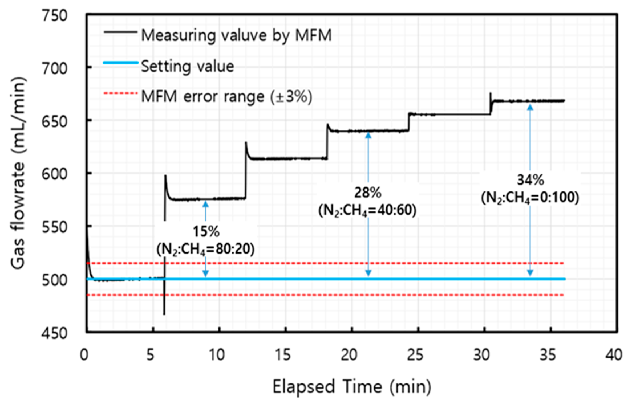
To check the limitations of the MFM, the gas flow was monitored by changing the mixing ratio of two gases (N
2 and CH
4), as shown in
Figure 2. Because the MFM was calibrated with nitrogen only, the flow rate measured by the MFM significantly deviated from the set flow that resulted from increasing the CH
4 mixing ratio. These characteristics were highly pronounced when the mixing ratio of CH
4 increased. The flow rate deviation also increased significantly, to 34%, when the entire mixed gas was converted to CH
4. This experiment directly demonstrates the limitation of the MFM in terms of flow measurement error, although we investigated only the effects of a single gas with a known mixing ratio. In addition, a real-time chemical reaction also produces a variety of byproduct gases and the changes in the mixing ratio of these gases. Therefore, it is virtually impossible to obtain a reliable flow rate in this environment. At present, the total gas flow rate is estimated using the loading information or by checking the gas composition ratio. However, it is difficult to obtain a reliable flow rate using these methods, even with consideration of the reliability range (±3%) of the MFM.
3.2. Validation of Gas Flow Measurement Using a Conservative Element
To check the reliability of the proposed method (Method II), we compared the measurement using an MFM and verified the gas flow for a continually flowing single gas or a mixture of two gases (N
2: CO
2 = 33:66), as shown in
Figure 3. Although the gas was injected at a constant rate (300 mL/min), the flow rate of the MFM showed a significant change. In addition, we observed high flow rates in the section where the internal temperature of the reactor remained high (850 °C), despite the loading of the fixed flow at 300 mL/min from the beginning. This reflected the temperature-induced gas expansion characteristics, and the gas flow was dependent on the internal temperature because this experiment was carried out under atmospheric pressure. Interestingly, the fluctuation of the gas flow measured by the MFM decreased gradually until the internal temperature of reactor reached 850 °C. When heating the furnace, the temperature of the furnace did not rise with the set point at an ideal constant ramping rate. As shown in
Figure 3, temperature fluctuation was derived from the degree of heater power, which appeared to be the result of gas flow fluctuation. Moreover, gas flow measured by both the MFM and a conservative element gradually decreased immediately after reaching the reaction temperature of 850 °C. According to the ideal gas equation (PV = nRT), temperature and pressure are the only factors that control the volumetric expansion of gas. Considering that our experiments were conducted in an open system in which the pressure was negligible, the tendency for the gas flow to decrease even at the constant temperature of 850 °C is difficult to understand. These patterns were observed in experiments applied to both single and mixed gases. Nevertheless, the gas flow rates identified only for the single gas using the MFM and those using Method II were consistent (
Figure 3a). By comparison, when a mixed gas of N
2 and CO
2 was injected, there was a significant difference depending on the measuring method (
Figure 3b). Even considering the gas conversion factor from the injected gas mixing ratio, the gas flow measured using the MFM differed from the injection flow. Unlike that of the MFM, the flow using Method II was consistent with the total injected flow rate (300 mL/min), although this was limited within the measuring interval. This suggests flow measurement using a conservative element is superior to that undertaken using mechanical devices such as an MFM.
We also estimated the reaction paths by precisely measuring the gas flow rate.
Figure 4 illustrates the changes in each gas composition identified via the gas analysis. In terms of flow rate contribution, the flow rate with N
2 as a conservative element was consistent with the injection flow (200 mL/min). This result demonstrates the high reliability of the gas flow measurement using the conservative element (Method II). However, CO
2 showed a flow rate lower than the injection flow (100 mL/min) in a certain section (620–850 °C). In the above section of lower CO
2 flow, the opposite result was found for CO, and the flow rate value was also the same as the flow reduction of CO
2. Although CO was not injected in this experiment, it appears that the injected CO
2 was converted to CO in a certain section by the Boudouard reaction (CO
2(g)+C
(s)↔2CO
(g) at over 700 °C) [
10].
3.3. Application to Manufacturing Activated Carbon Process
We applied the chemical activation to the manufacture of activated carbon in this study. The chemical activation is a reaction in which a pore is formed using potassium hydroxide (KOH) [
2,
3,
11], as given in Equations (3)–(7), and various gases with different components are generated. Therefore, the components and composition of the gas change in real time due to this series of chemical reactions, so the flow rate measured by the MFM is less reliable.
In the above-mentioned process, the inert gas (N
2) is continuously introduced to create an inert atmosphere in the reactor. The total flow rate was estimated using the injected inert gas (N
2). Considering that the frequency of measurement for five gases (H
2, N
2, CH
4, CO, and CO
2) is approximately 20 min, there was a difference in accuracy obtained using the MFM measurement of two seconds. However, the patterns of flow rate according to these two methods were similar, as shown in
Figure 5a. The flow rate deviation between these two methods increased by up to 30% in the section where the reaction progressed further, which resulted from severe changes in the property and content of the byproduct (
Figure 5b). Overall, flow rates directly measured by the MFM were somewhat higher, and appear to be overestimated by the change in gas composition, as confirmed in
Figure 2. In contrast, the gas flow was not detected in certain periods (approximately 120 min) (
Figure 5a). The reactor rotates during entire reaction periods, and fine particles float therein. In addition, inert gas is also continuously supplied to prevent the combustion of carbon precursors. Considering that the flow was not measured immediately after the flow increased, we believe that floating particles were also discharged during the reaction, which affected the MFM.
The proposed method, which calculates based on the volume fraction of the conservative element, enables the estimation of unknown components as part of the reaction gas.
Figure 5b calculates each of the produced gas fractions according to reaction time. In this experiment, only five gas phases, the main chemical species of the activation reaction, were analyzed, as identified in Equations (3)–(7). As shown in
Figure 5b, approximately 10% of the unknown components were also detected in the main reaction section. These results are also well explained in the generation of CH
4, which was not the main byproduct gas, even in a small proportion of the chemical activation. Methane is obtained in the side reactions (CO
2+4H
2→CH
4+2H
2O at 200–500 °C) from byproduct gases [
3]. This gas fraction of CH
4 was observed in accordance with the section in which a large quantity of H
2 was generated.
Figure 6 compares the instantaneous flow rate of the byproduct gas in the chemical activation according to the measuring method. With the exception of the flow during which the MFM was malfunctioning, the measured instantaneous gas flow rates are distributed above the line of equality, implying that the gas flows obtained using the MFM appear to be overestimated. This is more pronounced in the section where the gas generation is higher due to the variety of gas composition, as shown in
Figure 5b.
4. Conclusions
In this study, we analyzed the applicability of the conservative element as a reliable method for measuring gas flow rate during a chemical reaction by comparing it with a mechanical device (MFM). The MFM can obtain a reliable flow rate by measuring the mass value of the targeted gas. However, the reliability of the MFM is affected by the various gases produced in the chemical reaction and changes in the gas composition. In contrast, the conservative element is chemically stable, and its concentration in the reaction is determined only by physical mixing with the byproduct gases generated. Because the gas flow using the conservative element is not affected by the gas composition and mixing ratio, this approach can be used without any limitations in the measurement range. We expect this approach to fundamentally overcome the limitations of the mechanical devices. However, for this method, a quantitative analysis must be conducted of the conservative species in the discharge gas, which is closely related to the data collection interval of the gas analyzer. In future study, we will investigate technology for rapidly monitoring the conservative element to obtain more reliable measurements of gas flow.
Author Contributions
Conceptualization, S.-H.K.; methodology, G.L.; investigation, G.L.; data curation, G.L., S.-H.K.; writing—original draft preparation, S.-H.K.; writing—review and editing, S.-H.K., G.L.; project administration, S.-H.K. All authors have read and agreed to the published version of the manuscript.
Funding
This research was supported by Korea Environment Industry & Technology Institute (KEITI) through a project to develop eco-friendly new materials and processing technology derived from wildlife programs, funded by Korea Ministry of Environment (Project No. RE202101524) and the Ministry of Trade, Industry, and Energy Technology as Innovation Program (Project No. 20013038).
Institutional Review Board Statement
Not applicable.
Informed Consent Statement
Not applicable.
Data Availability Statement
Not applicable.
Conflicts of Interest
The authors declare no conflict of interest.
References
- Tian, Y.; Liu, P.; Wang, X.; Zhong, G.; Chen, G. Offgas analysis and pyrolysis mechanism of activated carbon from bamboo sawdust by chemical activation with KOH. J. Wuhan Univ. Technol. Mater. Sci. Ed. 2011, 26, 10–14. [Google Scholar] [CrossRef]
- Punsuwan, N.; Tangsathitkulchai, C.; Takarada, T. Low temperature gasification of coconut shell with CO2 and KOH: Effects of temperature, chemical loading, and introduced carbonization step on the properties of syngas and porous carbon product. Int. J. Chem. Eng. 2015, 2015, 481615. [Google Scholar] [CrossRef] [Green Version]
- Lee, G.B.; Park, J.E.; Hwang, S.Y.; Kim, J.H.; Kim, S.H.; Hong, B.U. Comparison of by-product gas composition by activations of activated carbon. Carbon Lett. 2019, 29, 263–272. [Google Scholar] [CrossRef]
- Grochala, W.; Khriachtchev, L.; Räsänen, M. Noble-gas chemistry. In Physics and Chemistry at Low Temperatures; Khriachtchev, L., Ed.; CRC Press: Boca Raton, FL, USA, 2011; pp. 419–446. [Google Scholar] [CrossRef]
- Grandinetti, F. Gas-phase ion chemistry of the noble gases: Recent advances and future perspectives. Eur. J. Mass Spectrom. 2011, 17, 423–463. [Google Scholar] [CrossRef] [PubMed] [Green Version]
- Herschy, R.W. Hydrometry: Principles and Practice, 2nd ed.; Wiley: London, UK, 1999; p. 384. [Google Scholar]
- Takayanagi, K.; Gobeil, C. Dissolved aluminum in the Upper St. Lawrence Estuary. J. Oceanogr. 2000, 56, 517–525. [Google Scholar] [CrossRef]
- Kim, K.; Lee, J.S.; Oh, C.H.; Hwang, G.S.; Kim, J.; Yeo, S.K.; Kim, Y.K.; Park, S.M. Inorganic chemicals in an effluent-dominated stream as indicators for chemical reactions and streamflows. J. Hydrol. 2002, 264, 147–156. [Google Scholar] [CrossRef]
- Kim, S.H.; Kim, K.; Lee, M.H.; Jeong, H.J.; Kim, W.J.; Park, J.K.; Yang, J.S. Enhanced benthic nutrient flux during monsoon periods in a coastal lake formed by tideland reclamation. Esturies Coasts 2009, 32, 1165–1175. [Google Scholar] [CrossRef]
- Basu, P. Biomass Gasification, Pyrolysis and Torrefaction: Practical Design and Theory, 3rd ed.; Elsevier: London, UK, 2012. [Google Scholar] [CrossRef]
- Romanos, J.; Beckner, M.; Rash, T.; Firlej, L.; Kuchta, B.; Yu, P.; Suppes, G.; Wexler, C.; Pfeifer, P. Nanospace engineering of KOH activated carbon. Nanotechnology 2012, 23, 015401. [Google Scholar] [CrossRef] [PubMed]
| Publisher’s Note: MDPI stays neutral with regard to jurisdictional claims in published maps and institutional affiliations. |
© 2021 by the authors. Licensee MDPI, Basel, Switzerland. This article is an open access article distributed under the terms and conditions of the Creative Commons Attribution (CC BY) license (https://creativecommons.org/licenses/by/4.0/).

