Article

Mechanical Properties of Cement-Treated Soil Mixed with Cellulose Nanofibre

1
Geotechnical Engineering Department, Port and Airport Research Institute, National Institute of Maritime, Port and Aviation Technology, 3-1-1, Nagase, Yokosuka 2390826, Japan
2
Research and Development Center, Toa Corporation, 1-3, Anzencho, Tsurumi-ku, Yokohama 2300035, Japan
3
Civil Engineering Central HQ., Design Department, Toa Corporation, 3-7-1, Nishishinjuku, Shinjuku-ku, Tokyo 1631031, Japan
*
Author to whom correspondence should be addressed.
Appl. Sci. 2021, 11(14), 6425; https://doi.org/10.3390/app11146425
Submission received: 17 June 2021 / Revised: 8 July 2021 / Accepted: 10 July 2021 / Published: 12 July 2021
(This article belongs to the Special Issue Trends and Prospects in Geotechnics)

Abstract

:
Cellulose nanofibre (CNF), a material composed of ultrafine fibres of wood cellulose fibrillated to nano-order level, is expected to be widely used because of its excellent properties. However, in the field of geotechnical engineering, almost no progress has been made in the development of techniques for using CNFs. The authors have focused on the use of CNF as an additive in cement treatment for soft ground, where cement is added to solidify the ground, because CNF can reduce the problems associated with cement-treated soil. This paper presents the results of a study on the method of mixing CNF, the strength and its variation obtained by adding CNF, and the change in permeability. CNF had the effect of mixing the cement evenly and reducing the variation in the strength of the treated soil. The CNF mixture increased the strength at the initial age but reduced the strength development in the long term. The addition of CNF also increased the flexural strength, although it hardly changed the permeability.

1. Introduction

In recent years, it has become possible to produce cellulose nanofibre (CNF), which is a material composed of ultrafine fibres of wood cellulose fibrillated to nano-order level [1,2,3]. CNF is expected to be widely used because its strength is five times and its mass is one-fifth that of steel, and its thermal expansion is one-fiftieth that of glass. The characteristics of CNFs, such as high specific surface area, edibility, light weight, high strength, low thermal expansion, biodegradability, and biocompatibility, have been utilised to develop various applications. For example, transparent resins such as acrylics and epoxy resins are reinforced without much loss of their transparency (transparency reinforcement). The characteristics of light-weight and high-strength fibres are used to produce moulded products that are as strong as steel but one-fifth their mass by injecting phenolic resin into nanofibre sheets and then laminating and curing them. In addition, the thixotropy (the property that the fluidity increases when an external force is applied) of CNF solutions has already been used to commercialise ball-point pen inks, which prevent dripping and ease writing. In the field of concrete, the addition of CNFs to improve the strength of concrete has been studied [4,5,6]. This is attributed to its ability to accelerate the cement hydration reaction as well as to the high strength of CNF itself. The use of CNF as a stabiliser to prevent the separation of concrete compositions and bleeding before solidification, and as an additive to increase the flowability required in the pressure injection method using thixotropic properties, are being investigated and have been partly implemented.
In the field of geotechnical engineering, very little progress has been made in the development of techniques for using CNFs. The authors have focused on the use of CNF as an additive in cement treatment for soft ground, where cement is added to solidify the ground, for example, by the deep mixing method [7] to improve the ground and to construct geotechnical structures. This is because cement treatment is a relatively inexpensive and highly reliable ground improvement method. Although it is widely used, there are still some problems such as brittleness, low tensile strength, strength variability, and low short-term strength. If more cement is added to solve these problems, the environmental impact will increase. If the long-term strength of the treated soil is too high, the treated soil could make rehabilitation of the geotechnical structure difficult. The possibility of reducing these problems using the CNF effect can be considered as follows: (1) The high strength of fibres increases the strength of the treated soil and reduces the risk of brittle or tensile failure. (2) As in concrete, CNFs accelerate the cement hydration reaction. (3) Owing to its water absorption and thickening properties, shear strength can be expected to develop immediately after stirring. (4) Thixotropy improves uniformity when stirring and mixing cement, and it ensures fluidity when pumping the treated soil in the slurry state before solidification. (5) Dispersibility increases uniformity during the stirring and mixing process. Previous studies have shown that fibrous materials of a few millimetres in length can be used for mixing with the treated soil [8,9,10,11,12,13,14,15]. The mixture of long fibres can have the effect described in (1) above, although not many other effects can be expected. When using existing ground improvement machines, such as deep mixing machines, it is difficult to stir long fibres into the treated soil, which presents a number of challenges for on-site use. Carbon nanotubes (CNTs) are similar to CNF, and research has been conducted on mixing them into the treated soil [16,17]. In these studies, the addition of these materials was found to increase the initial strength of the treated soil, even at the nano level. However, CNTs are poorly dispersible and require the addition of dispersants. By contrast, CNF is hydrophilic and highly dispersible in its own right, making it easy to mix directly with water or soil. This suggests that the use of CNFs in cement treatment is useful.
As mentioned above, the effect of mixing CNF can be predicted, but it is not simply a matter of mixing CNF. The method of mixing CNF and cement needs to be studied, because adding CNF in gel form requires more cement to solidify the soil, as water is also added. It is also not clear whether CNF of increasing plasticity can be stirred evenly. In contrast to concrete, the properties of soils are diverse and need to be carefully investigated to ensure that CNFs are effective. There are different types of CNFs as well as soil, and it is necessary to know which CNF should be combined with which soils. In the first place, it has not been demonstrated that mixing CNFs can solve the problems of cement-treated soil. Therefore, the authors’ group has been studying the method of adding CNF in the cement treatment method, understanding the effect of mixing CNF, and investigating its use in an actual ground improvement site. This paper presents the results of a study on the method of mixing CNF, the strength and its variation obtained by adding CNF, and the change in permeability. Strength and permeability are important parameters because cement treatments are used to increase the strength of soft ground and impervious materials. If the study finds the mixing method and the improved properties in terms of strength and permeability, CNF will clearly be of great use in the field. Incidentally, the purpose of this study is not to clarify the mechanism of the effect of CNF but to investigate how to mix CNF and whether the effect of CNF can be observed in the solidification process.

2. Materials and the Mixture Method

2.1. Characteristics of CNF Used

There are many types of CNFs in terms of raw materials and manufacturing processes, and the ones used in this study were two typical commercially available CNFs (TEMPO-CNF and ACC-CNF). Two types of ACC-CNFs with different raw materials were used, which are referred to as ACC-CNF-S and ACC-CNF-B. The tests used these three types of CNFs and two states of TEMPO-CNF: a gel containing 2% CNF and a powder containing 90% CNF. The CNFs used are listed in Table 1. CNF is generally supplied in gel form mixed with water, although when mixed with soil to produce cement-treated soil, the soil includes a large quantity of water. The addition of water, which is included in the cement slurry, and CNF gel to the soil causes the soil to soften, and more cement is required to solidify the soft ground. Powdered CNF was also used in this study to investigate whether it might be possible to mix it with soil.
The production methods for the CNFs are different, and their degrees of fibrillation are also different. TEMPO-CNF is produced from wood pulp by a chemical defibration technique called TEMPO-mediated oxidation [18]. It is characterised by a very fine and uniform fibre width, which is as thin as approximately 3 nm. On the other hand, ACC-CNF is produced from bleached pulps of softwood or bamboo by a physical defibration technique called the aqueous counter collision (ACC) method [19]. CNF derived from soft woods is referred to as ACC-CNF-S, and that derived from bamboo is called ACC-CNF-B. These CNFs are characterised by their low chemical environmental impact as they are fibrillated using only water and raw materials, their amphiphilicity, and the concise control of the fibre width due to the gradual refinement of the fibre by repeated processing. The fibre width ranges from a few nanometres to several millimetres, depending on the number of treatments.

2.2. Characteristics of Soil and Cement

Two types of soil were used as base materials: Kasaoka clay, which is powdered clay manufactured from a mudstone in Okayama Prefecture, Japan, and Kawasaki clay, which is marine clay collected from the seabed of the Port of Kawasaki. The properties of each sample are listed in Table 2. Kasaoka clay is classified as high-liquid clay with a liquid limit of 62.1%. Kasaoka clay has few impurities and is uniform. Kawasaki clay is classified as low-liquid clay with a liquid limit of 41.0%. Kawasaki clay is a natural marine clay collected by dredging and contains impurities (e.g., small amounts of shells and gravel). A small amount of water was added as a pre-treatment to liquefy it, and it was passed through a 2 mm sieve to remove impurities before the cement treatment. Artificial seawater was added until the liquid limit ratio became 1.55.
Three types of cement were used for the solidification process: ordinary Portland cement, high-early-strength Portland cement, and blast-furnace cement type B. Portland cement was used to determine the basic properties of the treated soil mixed with CNF. In Section 4, the results of the study on the strength variability of the treated soil are discussed by making an assumption about the treated soil in the field. Here, blast-furnace cement type B was used, assuming the soil in the field was treated. In Japan, this type of cement is frequently used for ground improvement in port and in harbour engineering. Blast-furnace cement type B is a relatively inexpensive cement that is prepared by adding blast-furnace slag powder to cement. It also has high durability against seawater and chemical substances, and low leaching of hexavalent chromium.

2.3. Mixture Procedure of Soil, Cement, and CNF

2.3.1. Method 1

An attempt was made to add and mix CNF uniformly into the soil–cement mixture in the laboratory. This was performed to reduce the variation between the specimens and to confirm the effect of CNF in the treated soil mixed with CNF. Figure 1 shows the procedure used to prepare the specimens. Three types of CNFs in gel form (TEMPO-CNF, ACC-CNF-S, and ACC-CNF-B) were prepared and watered. Considering the possibility that the gelatinous material might not be mixed uniformly into the soil, water was added until it was no longer gelatinous to ensure uniform mixing. Cement slurry was also prepared by adding water to ordinary Portland cement. As shown in the mixture procedure (Figure 1), the CNF solution and cement slurry were mixed first and then added to and mixed with dry and powdered Kasaoka clay. The reason for mixing the powdered clay with the CNF solution and cement slurry is that if they were mixed with the wet soil, too much water would be present in the treated soil, and a large quantity of cement would be needed to solidify the soil. As this is not practical, the mixing of CNF and cement into wet clay was attempted using Method 2.
The soil mixer used for mixing was of 5 L capacity in accordance with JIS R5201 [20], with a mixing time of 5 min. Figure 2 shows the soil treated immediately after mixing. As shown in the figure, it can be observed that the flowability of the mixture without CNF is high, whereas that of the mixture with CNF is low. This was due to the water absorption and thickening properties of the CNFs. However, cement was considered to have been well mixed because of its high fluidity at a high strain rate near the agitator blades, which was induced by the thixotropic nature of CNF. The mixed soil was packed in unconfined compression test moulds (50 mm diameter × 100 mm height cylindrical) and cured in a constant-temperature curing room at 20 ± 2 °C and a humidity of more than 95% for a specified period.
Table 3 shows the mixing proportions of cement, CNF, water, and soil for the treated soil prepared by Method 1. When CNF was added, the ratio of the dry weight of CNF to the dry weight of soil was defined as the CNF addition rate, α, which was set to α = 1.0%. The reason for setting α = 1.0% is that in a previous study, the effect of CNF was not clearly visible unless it was mixed with α = 1.0%. Cement was added in the ratio of approximately 100 kg dry weight per unit volume of soil mixed with all other materials except cement. The dry weight ratio of cement to soil was 13.8%. This was slightly less than the amount added in the deep mixing method, which is one of the most common ground improvement methods used on site. Cement was not added as a powder but as a cement slurry. The water–cement ratio was set to w/c = 7.0. Considering the water contained in all soil mixtures, the water content ratio was approximately 85%. The treated soil mixed using Method 1 was subjected to unconfined compression tests, and the test results are discussed in Section 3.

2.3.2. Method 2

As mentioned above, CNF in gel form was used in Method 1 with the aim of ensuring uniform mixing. However, water in the gel is added to the soil to increase the amount of CNF, and consequently, more cement is required to solidify the soil. To overcome this problem, dry powdered CNF was added to wet clay in Method 2 instead of the gel form of CNF. This is a more practical method for addition in the field. It is also practical to use high concentrations of CNF, even if it is difficult to produce powdered CNF. Figure 3 shows the mixture procedure for specimen preparation using Method 2. Powdered CNF (TEMPO-CNF) and cement (blast-furnace cement type B or high-early-strength cement) were mixed well in advance. Separately, Kawasaki clay was water-adjusted to obtain a liquid limit ratio of 1.55 or 1.95; then, they were mixed and stirred. For the specimens used in the permeability tests, ACC-CNF-S mixed with high-early-strength cement was also prepared, because the powdered ACC-CNF-S was not available. The gel form was used in this type of specimen.
The soil mixer used for mixing was the same as that used in Method 1, and the mixing time was set to 1 or 5 min. A 5 min agitation makes the cement-treated soil uniform both with and without CNF. For this reason, the mixing time was shortened to 1 min for some specimens, which deliberately created a condition of insufficient mixing. It was easy to predict that without CNF mixing, stirring would be inadequate, and this test series was used to investigate whether the addition of CNF would promote uniform mixing of the cement. The specimens used in the permeability tests required uniformly treated soil. This was why a sufficient mixing time of 5 min was provided. Figure 4 shows the immediate aftermath of a short mixing time of 1 min for the specimen. In the figure, it was easily possible to visually distinguish between cemented and uncemented areas in the soil without the CNF mixture. On the other hand, in the soil mixed with CNF, there was no unevenness of mixing as far as could be visually observed, indicating the effect of the addition of CNF. This was attributed to the effects of the thixotropy, which facilitated mixing of the soil, and the homogeneous dispersion, which mixed cement well, although the water absorption and thickening properties of CNF reduced the flowability. The mixed soil was packed in unconfined compression test moulds (50 mm diameter × 100 mm height cylindrical) and cured in a constant-temperature curing room at 20 ± 2 °C and a humidity of over 95% for a specified period.
Table 4 and Table 5 show the mixing proportions of cement, CNF, water, and soil for the treated soil prepared by Method 2. The tables show the proportions of the specimens for the tests to examine the strength variability and permeability tests, respectively. The ratio of CNF addition was set to α = 1.0%, which showed the effect of CNF, except for the soil treated with ACC-CNF-S, for which the ratio was set to α = 0.5%. This was because in this CNF, the powdered form was not available, and the gel form was used. The larger the amount added, the more water was added to the treated soil. Cement was added in the ratio of approximately 50 or 80 kg dry weight per unit volume of soil mixed with all other materials except cement. The dry weight ratio of cement to soil was 4.9% or 10.0%. These values are lower than the amounts added in the deep mixing method, especially the 4.9% cement addition, which was so small that the specimen could be easily broken by hand. By reducing the amount of cement in this way, the effect of CNF on cement mixing was more clearly visible. Considering the water contained in all the soil mixtures, the water content ratio was approximately 60% or 80%. Thirty specimens were prepared for each proportion with and without CNF, because the variability was expected to be large in the specimens prepared with 1 min of mixing. The treated soil prepared with these proportions was subjected to unconfined compression tests and permeability tests, and the test results are discussed in Section 4 and Section 5.

3. Effect of CNF on Strength Increase

3.1. Unconfined Compressive Strength

Unconfined compression tests were conducted on the specimens prepared by Method 1 to examine the strength of the treated soil. The method was in accordance with JIS A 1216 and JGS 0511 [21,22]. In the tests, a cylindrical specimen of 50 mm diameter × 100 mm height was compressed in the one-dimensional direction at a strain rate of 1%/min to investigate the axial compressive stress and strain. The strength of the soil was determined by taking the peak value of the relationship as the unconfined compressive strength. The tests were carried out 7, 28, and 112 days after preparing the specimens. The strength of treated soil is known to increase linearly with the logarithmic axis of time, and the specimens were cured for four times as many days each. The stress–strain relationship for each test case is shown in Figure 5. Figure 6 shows the time change of the unconfined compressive strength, together with the values normalised to the strength of the treated soil without CNF.
The strength at the age of 7 days was 1.4–1.5 times higher in the soil treated with CNF than in the soil without CNF treatment, indicating the effect of CNF. The strength of the soil at 28 days of age was 1.1–1.3 times higher than that of the soil without CNF treatment, whereas the ratio of these strengths was smaller than that of the soil at the age of 7 days. At the age of 112 days, the trend was more pronounced, and the strength of the treated soil with TEMPO-CNF was lower than that of the treated soil without CNF. The strength of the soil treated with ACC-CNF was similar to that of the treated soil without CNF. This tendency can be clearly observed in Figure 6b, where the strength ratios of the treated soil without CNF are shown. It was found that the CNF mixture increased the strength at the initial age of the treated soil but reduced the strength development in the long term. This trend is more evident for the TEMPO-CNF. Increasing the initial strength and reducing the long-term strength is advantageous in cement treatment. As mentioned in Section 1, one of the challenges of cement treatment is the low short-term strength, and if the long-term strength is too high, the treated soil can hinder the rehabilitation of geotechnical structures. CNFs have the potential to solve these problems. It is not clear how the strength development was suppressed with age, although it was possible that in TEMPO-CNF, the carboxylic groups of CNF reacted with the calcium ions of cement and aggregated, suppressing the cement hydration reaction and reducing the increasing rate of long-term strength. On the other hand, the failure strains (axial strains at the peak value) of the soil treated with TEMPO-CNF were not very large, whereas those of the soil treated with ACC-CNF were large. The addition of ACC-CNF increased the failure strain by a factor of 2, indicating that some types of CNFs could mitigate the brittleness, which is a major problem in cement-treated soil.
The soil treated with CNF was photographed using an optical microscope. Figure 7 shows micrographs of the sheared surfaces (peeled and sliding surfaces) produced by the unconfined compression tests. In the photographs of the soil treated with CNF, no fibrous material could be observed in the TEMPO-CNF specimen, whereas it could be observed in the ACC-CNF specimen. The fibrous material was considered to be a CNF. TEMPO-CNF has a high degree of friability, which cannot be captured by optical microscopy, but a bunch of CNFs was seen in the void. Fibrous material could be observed at any given position in the ACC-CNF specimen, suggesting that the CNF was uniformly agitated. It was assumed that the uniformly mixed CNFs contributed to the strength increase. In addition, a number of small voids appeared in the soil treated with CNF, especially in the case of the TEMPO-CNF mixture. This was attributed to the reduced fluidity of the CNF mixture, which allowed air to enter the soil. A few small voids did not contribute significantly to the strength loss, and therefore would not affect the strength development much.

3.2. Flexural Strength

One of the problems of cement-treated soil is its low tensile and flexural strengths. As it was anticipated that the CNF mixture would improve these properties, some tests were conducted to investigate the flexural strength. Since the flexural failure of treated soil depends on its tensile strength, its flexural strength can indirectly indicate the tensile strength of the treated soil. The method was implemented in accordance with JIS R 5201 [20]. In this test, a prismatic specimen (40 mm high × 40 mm deep × 160 mm long) was placed on support rolls placed at a distance of 100 mm, and the roll was loaded in one direction at the centre of the specimen at a loading rate of 50 N/s. Then, the relationship between bending stress and deflection was investigated, and the peak value was taken as the flexural strength. Figure 8 and Figure 9 show the relationship between the bending stress and deflection for each test case and the micrographs of the tensile fracture surfaces, respectively.
The flexural strength of the specimens without CNF was approximately 400–470 kN/m2, which was 25–50% of the unconfined compressive strength, regardless of the age of the specimens. Previous studies [23,24,25] showed that the flexural strength was approximately 20–50% of the unconfined compressive strength (on average around 30%), and our results were consistent with these findings. The flexural strength of the specimens with TEMPO-CNF was 590 kN/m2 (at 28 days of age) and 810 kN/m2 (at 112 days of age), indicating that the flexural strength increased with the addition of CNF. The ratio of flexural strength to unconfined compressive strength was as large as 50–65%, which was not the case for normal cement-treated soil. The increase in flexural strength can be attributed to the increase in the tensile strength. The flexural strength of the specimens with ACC-CNF was 560 kN/m2 (at 28 days of age) and 660 kN/m2 (at 112 days of age), and the ratio to the unconfined compressive strength was 33–56%. The addition of ACC-CNF also increased the flexural strength, although not as much as that of TEMPO-CNF. The low flexural and tensile strength of the treated soil is frequently a problem in the field, and the addition of CNF was found to be a possible solution to this problem. The micrographs showed fibrous material in the ACC-CNF specimen, as well as in the sheared surfaces from the unconfined compression test, while the TEMPO-CNF specimen showed voids and material that could be CNF in the void.

4. Effect of CNF on Strength Variability

4.1. Dispersion of Unconfined Compressive Strength

CNF has dispersive properties that make substances in liquids homogeneous, and this property has been considered for use in a variety of applications. CNF is also expected to improve the dispersibility of cement when it is mixed with the soil, and its thixotropy property increases the uniformity of cement. The uniform mixing of cement with soil could reduce the variation in strength. This section presents the test results regarding the effect of CNF mixing on the strength variability. It is important to consider variability, as a reduction in the strength variability can reduce the design strength. Figure 10 shows the relationship between the frequency distribution of intensity occurrences and the design strength. During design, the percent defective is determined at the beginning, and the mean strength (design strength) is determined so that it is satisfied. As shown in the figure, the smaller the variance in strength, the lower the mean strength for the same percent defect. The advantages of reducing the strength and dispersion are significant. This reduces the risk that large dispersals will result in treated soil of extremely high strength as well as high cost of cement and high environmental impact of cement production. As mentioned before, large-strength treated soil can hinder the rehabilitation of geotechnical structures.
Unconfined compression tests were conducted at 28 days of age on a total of 60 specimens prepared by Method 2 with a short mixing time of 1 min. The axial compressive stress–strain relationships obtained from the tests are shown in Figure 11a,b. Figure 11c shows the results of the unconfined compression test of the treated soil used for the permeability test (preparation method: Method 2, mixing time: 5 min), which is discussed later in Section 5. Most of the peak strengths (unconfined compressive strengths) of the specimens without CNF were below 50 kN/m2, which was quite low. By contrast, the peak strengths of the specimens with CNF were relatively higher, with unconfined compressive strengths ranging from 100 to 350 kN/m2. Comparing the mean values, the unconfined compressive strength was 43 kN/m2 (without CNF) and 219 kN/m2 (with CNF); the strength ratio was significantly larger: 5.1 times. As the strength ratio of the well-mixed specimens with and without CNF at 28 days of age was 1.1–1.3 times, as mentioned in Section 3, the large strength ratio of 5.1 indicates that the addition of CNF caused the cement to mix evenly with the soil. The failure strains of the specimens with CNF were relatively low owing to the higher strength of the specimens. The average failure strains were 3.9% (without CNFs) and 1.4% (with CNFs).
Figure 12 shows photographs of the sheared surfaces generated by the unconfined compression tests. The sheared surface of the specimen without CNF showed that the solidified portions were scattered within the poorly solidified soil. The unconfined compressive strength was extremely low, which was probably because the solidified portions were not continuous. On the other hand, the sheared surface of the specimen with CNF appeared to be homogeneous, suggesting that the cement spread over the whole specimen, and that this condition led to the development of a relatively high unconfined compressive strength.

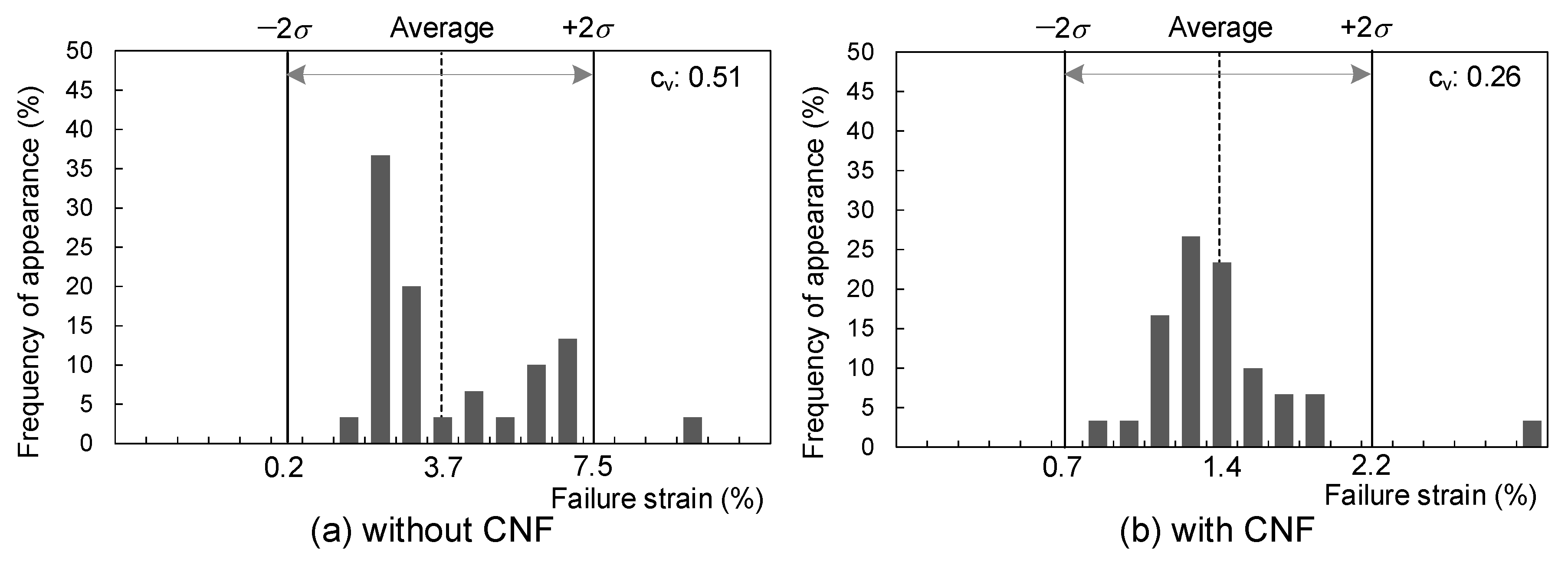
4.2. Evaluation of Variability

Here, variations in the unconfined compressive strength and failure strain were discussed. Figure 13 and Figure 14 show the frequency distributions around the mean values of the unconfined compressive strength and failure strain of the specimens, respectively. Although the strengths of the specimens without CNF were generally low, some specimens developed significant strength, resulting in a strength coefficient of variation of 0.56. On the other hand, the variation coefficient of the strength of the specimens with CNF was 0.33, and the frequency distribution was in the range of 2σ, as shown in the figure. Thus, it was confirmed that the addition of CNF reduced the variation in strength in terms of the coefficient of variation of strength. The coefficients of variation of failure strain for the specimens without and with CNF were 0.51 and 0.26, respectively. For failure strain too, the addition of CNFs reduced the variability. The density and water content of the specimens were also measured, and no differences were observed between the specimens with and without CNF. This suggests that there was no difference in the properties of the base soil or the amount of cement added between the specimens with and without CNF, indicating that CNF had an effect on the strength of the specimens.
In this study, the amount of cement added was reduced so that the effect of CNF on cement mixing could be more clearly expressed. Considering the strength of the soil treated by the deep mixing method, the amount of cement was small. It will be important in the future to compare the variability of the specimens with increasing cement content. However, there are some methods that produce treated soil with lower strength than the deep mixing method. Examples include the pre-mixing method [26] and the pneumatic flow mixing method [27]. In these methods, the soil is mixed with cement in a mixer or in a pneumatic flow in a pipe and poured in situ before solidification occurs. Strengths of 100–400 kN/m2 at 28 days of age are generally expected with cement additions of approximately 50–100 kg/m3. The amount of cement added and the expected strength were similar to those in this study. If the mixing time is short for some reason, the soil could be extremely weak, as described above. Mixing CNFs could prevent such problems.

5. Effect of CNF on Permeability
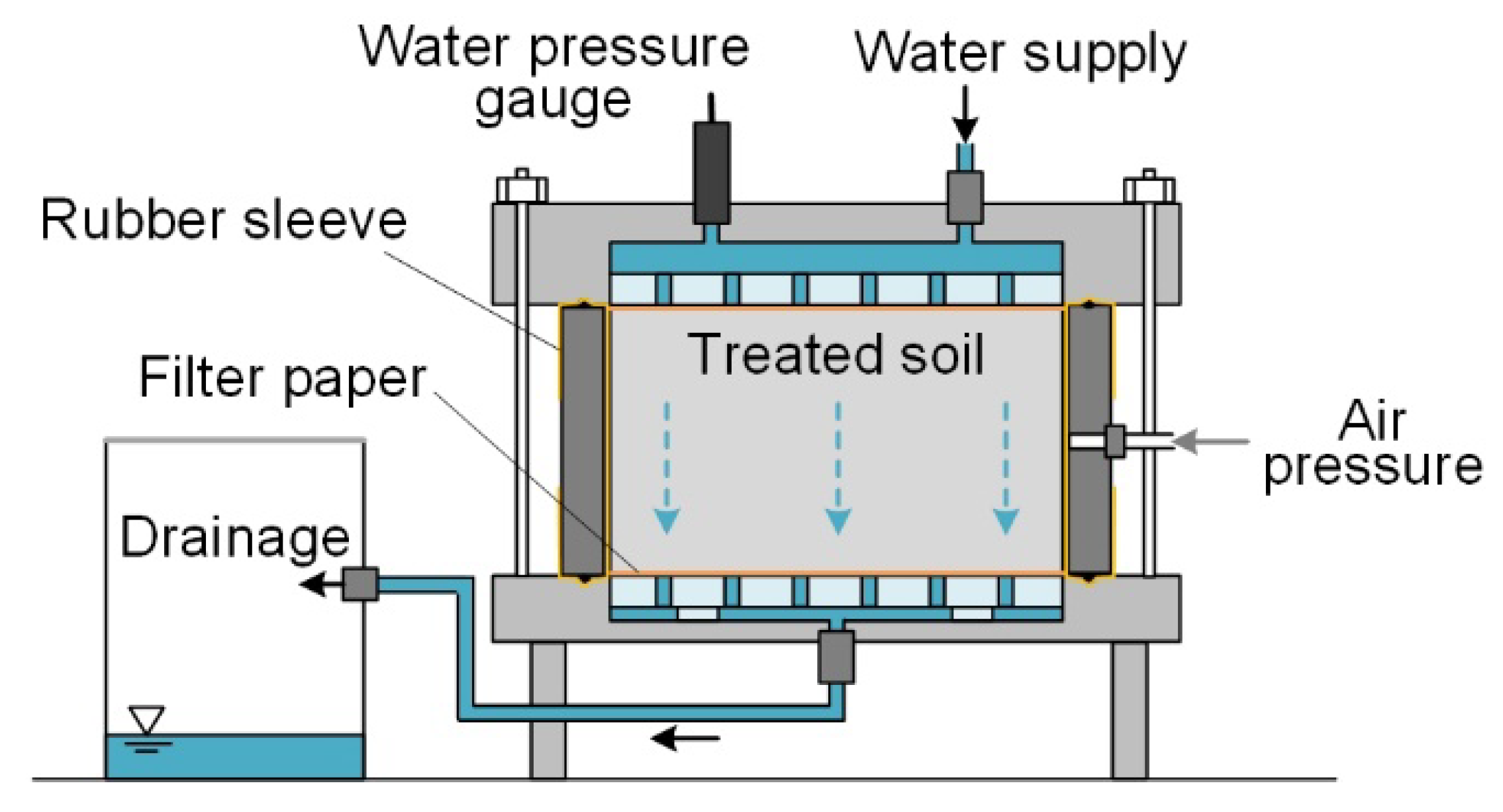
5.1. Test Method

In addition to the strength of the treated soil, its permeability was also investigated. Previous studies showed that the permeability of clayey soils decreases when they are mixed with cement [28,29,30]. The treated soil is occasionally used as an impervious material, and permeability is one of the most important aspects of the treated soil. In addition, a high permeability indicates that the calcium ions in the treated soil can easily diffuse to the outside, and therefore, permeability is an important parameter for evaluating the deterioration of the treated soil. It is known that treated soils start degrading from the exposed surface [31,32,33,34,35,36], which is one of the points that must be understood when using cement treatment in the field. This section discusses how the permeability changes with the addition of CNFs.
The specimens prepared using Method 2 were cured for more than 200 days. The unconfined compression test results of the specimens are shown in Figure 11c. As part of the specimen was used for the permeability test, the unconfined compression tests in this study did not use specimens of the size specified in JIS A 1216 and JGS 0511 [21,22]. It should be noted that because the compression tests were conducted on small prismatic specimens (15 mm wide × 15 mm deep × 30 mm high), the test results could contain errors. All other methods were implemented in accordance with the standards. The unconfined compression test results showed that the strength of the specimens with CNF was lower than that without CNF. This was in agreement with the trend of the results described in Section 3, where it was found that the addition of CNF reduced the long-term strength.
The remainder of the treated soil in the unconfined compression test was subjected to a permeability test. As there is no standard method for permeability testing of treated soil, the tests were conducted using the method utilised in the past study [37]. Figure 15 shows a conceptual diagram of the test apparatus. In this test method, a cylindrical specimen with a diameter of 50 mm and height of 30 mm was permeated by percolating water above the specimen, applying confining pressure from the side through a membrane. The lateral confining pressure prevented the upper pressurised water from leaking at the side of the specimen. The water pressure above the specimen was 400 kN/m2, and the average hydraulic gradient inside the specimen increased to 1361. This was because the permeability of the treated clayey soil was low, and the hydraulic gradient had to be increased to increase the drainage rate. The drainage water that passed through the specimen was collected to determine the permeability per unit time. The pH, calcium ion concentration, and sodium ion concentration were measured periodically in the collected effluent. The permeability period depended on the specimen: 114 days for ‘no CNF’, 114 days for TEMPO-CNF, and 49 and 97 days for ACC-CNF-S, respectively. The reason for the long-term measurements was to check whether the addition of CNF would change the condition of the effluent, as it is known that continued permeability degrades the treated soil.

5.2. Test Results

Figure 16 shows the drainage rate per unit time and the chemically measured values for each day. Note that these values indicate the effluent collected at the time of measurement and not the accumulated effluent. The drainage rate per unit time, which indicates the permeability, showed that the permeability of the specimens with TEMPO-CNF was approximately 35% lower and that of the specimens with ACC-CNF was approximately 25% higher, depending on the type of CNF. It was not simply that the CNF itself clogged the pores and reduced the permeability. Figure 17 shows scanning electron microscopy (SEM) images of the permeable and non-permeable specimens. As shown in the images, the specimen with ACC-CNF-S contained fibrous material that could be considered as CNF, and the fibrous material formed a network. On the other hand, CNF did not appear in the specimen with TEMPO-CNF, because TEMPO-CNF has a high degree of fibrillation and cannot be observed at a magnification of 500 times. In any case, the amount of CNF added was found to be small and insufficient to close the pore space. The pore conditions of the soil particles were similar in all cases, and the reason for the change in permeability could not be determined from the SEM photographs. The reason for the change in permeability is not understood, although CNF may have influenced the cement hydration reaction, changing the amount of hydrate formed, or the hydrophilicity of the CNF itself may also have affected the permeability. Incidentally, a difference of 25–35% is not generally considered to be significant, as the permeability frequently varies by orders of magnitude depending on the pore conditions and the amount of cement added. It is necessary to conduct more tests on more specimens to improve the accuracy of the results. In other words, it could be said that the addition of CNF did not change the permeability significantly, at least on a per-digit basis.
The pH, calcium ion concentration, and sodium ion concentration of the drainage water were also measured and are shown in Figure 16. The drainage was the result of the pore water in the treated soil being pushed out, which indicates the state of the pore water. The pH values were similar, indicating that the addition of CNF did not change the alkaline atmosphere of pore water, and that the environment in all specimens was conducive to cement solidification. The concentration of calcium ions was higher in the TEMPO-CNF specimens. The low permeability of the specimens may have resulted in a higher supply of calcium from the cement hydrate to pore water, or the calcium bound to the carboxylic groups may have been more easily leached than the cement hydrate. Sodium ions were detected early, but not thereafter. The fact that the base soil was marine clay and that the water content ratio was adjusted with artificial seawater suggested that the treated soil contained sodium. The concentration of sodium ions in the specimens with TEMPO-CNF was higher than that in the specimens without TEMPO-CNF, suggesting that the sodium bound to the carboxylic groups may have leached out. The effect of CNF was not apparent in terms of the chemical properties of the effluent.

6. Conclusions

This study investigated methods of mixing CNF, the increase in strength and the reduction of variability by adding CNF, and the change in permeability. The results can be summarised as follows:
  • The method of mixing either the soil or the additive (cement, CNF) in a dry state was attempted to reduce the amount of water in the treated soil. Both methods could be used, but for on-site mixing, it was considered more practical to mix cement and CNF in dry powder or highly concentrated gel form.
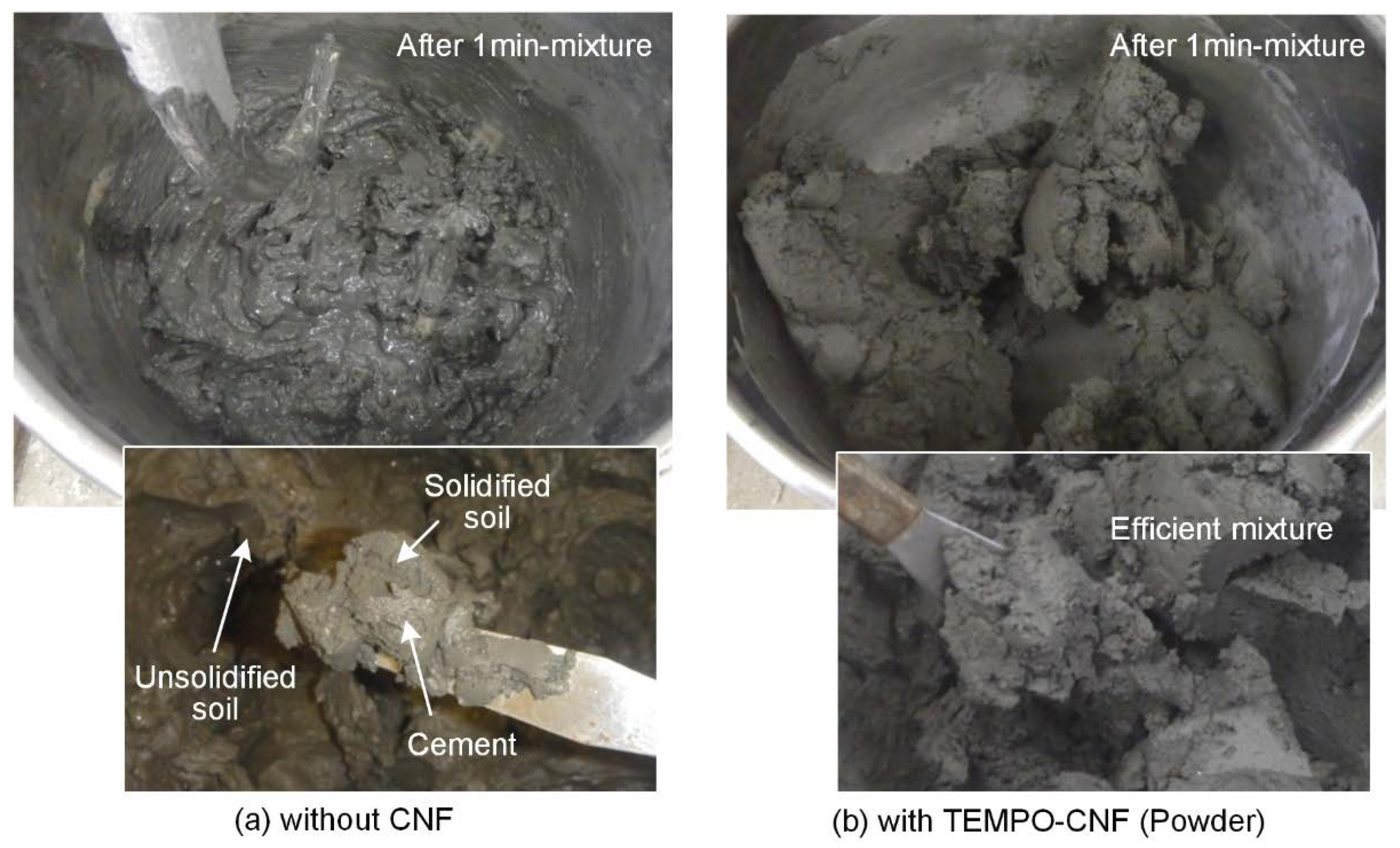
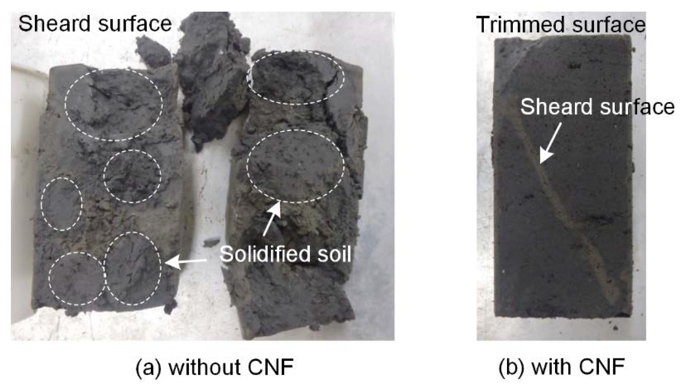
  • During the mixing of cement and soil, the water absorption and thickening properties of the CNF reduced the flowability, but as a result, it was possible to mix the cement evenly, which was probably because of the other effects at work. In addition, when the mixing time was extremely short, unevenness was observed between the solidified portions and those that did not solidify in the specimen without CNF, whereas the treated soil was produced uniformly in the specimen with CNF.
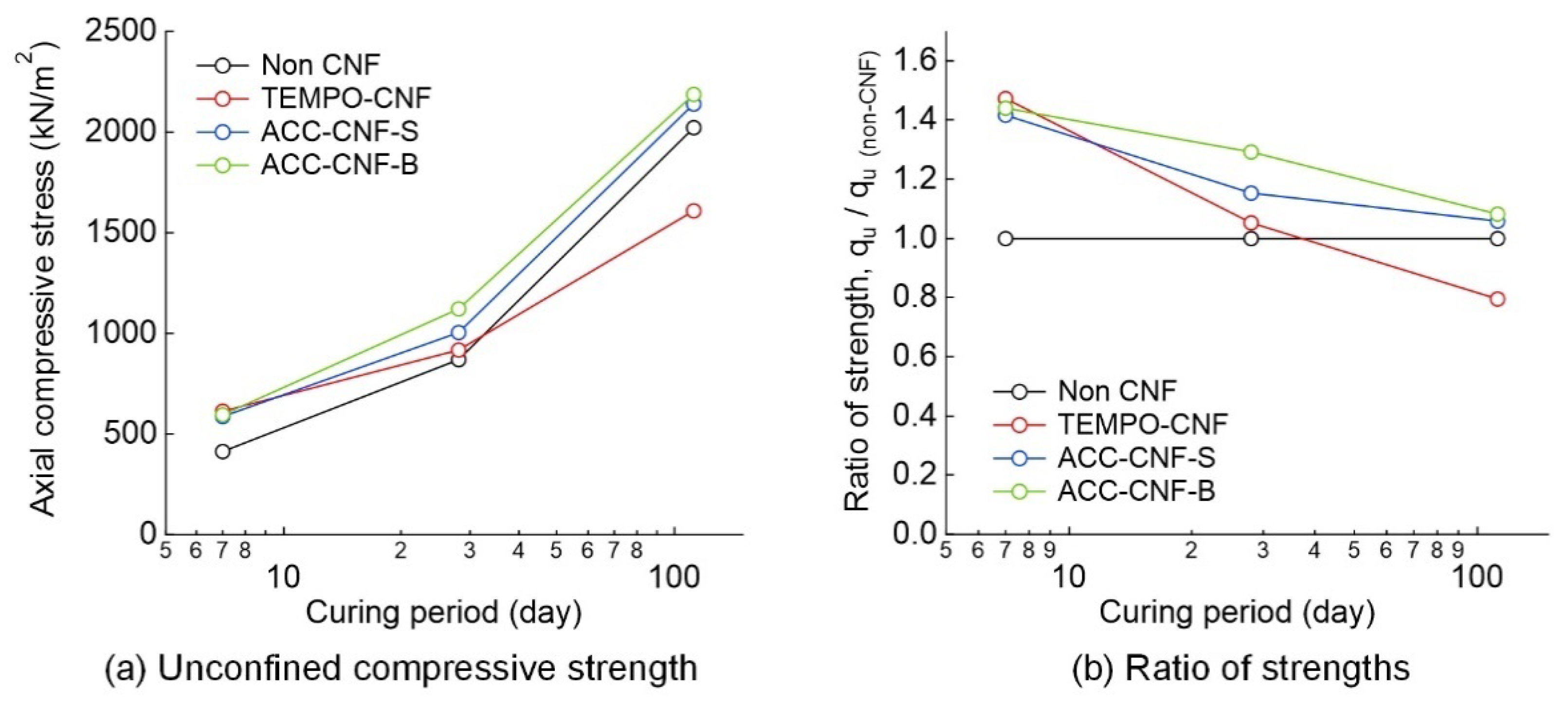
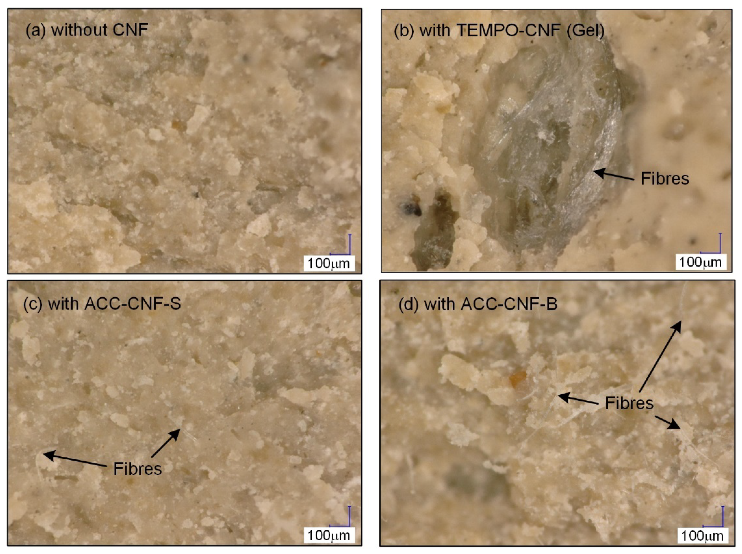
  • In regard to the strength development characteristics over time, it was found that the mixture of CNF increased the strength at the initial age, but it reduced the strength development in the long term. Increasing the initial strength and reducing the long-term strength can be advantageous for cement treatment. Observation of the sheared surface showed that a fibrous material, which was considered to be CNF, was widely mixed in the specimens to which CNF with a relatively low degree of friability was added.
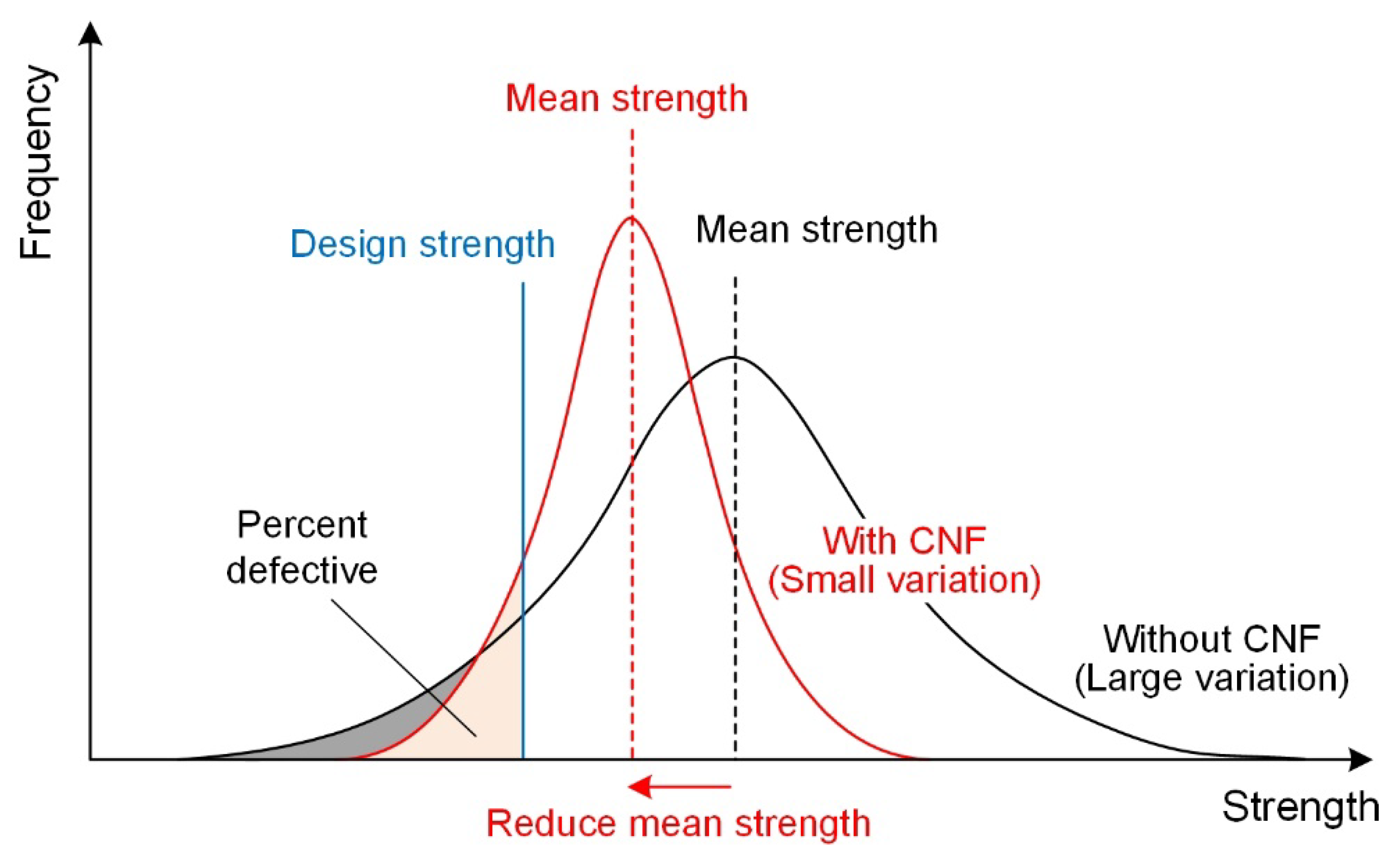
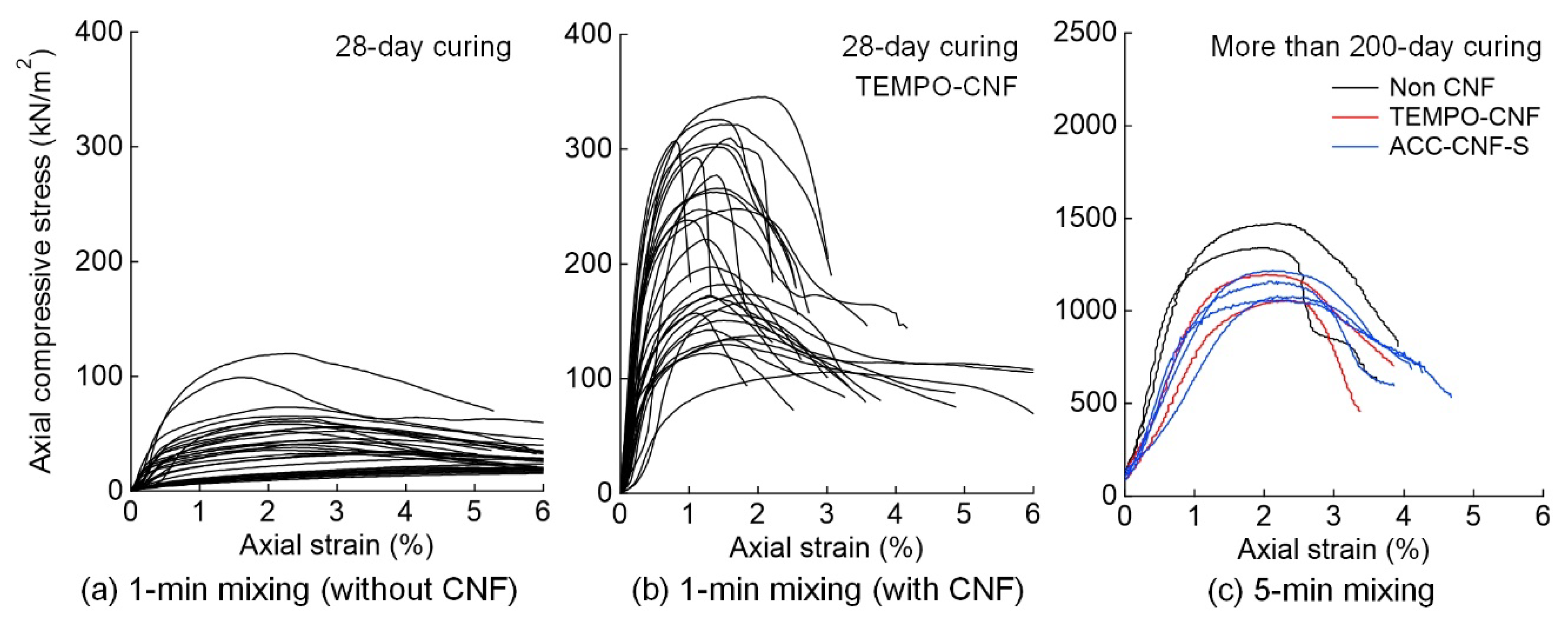
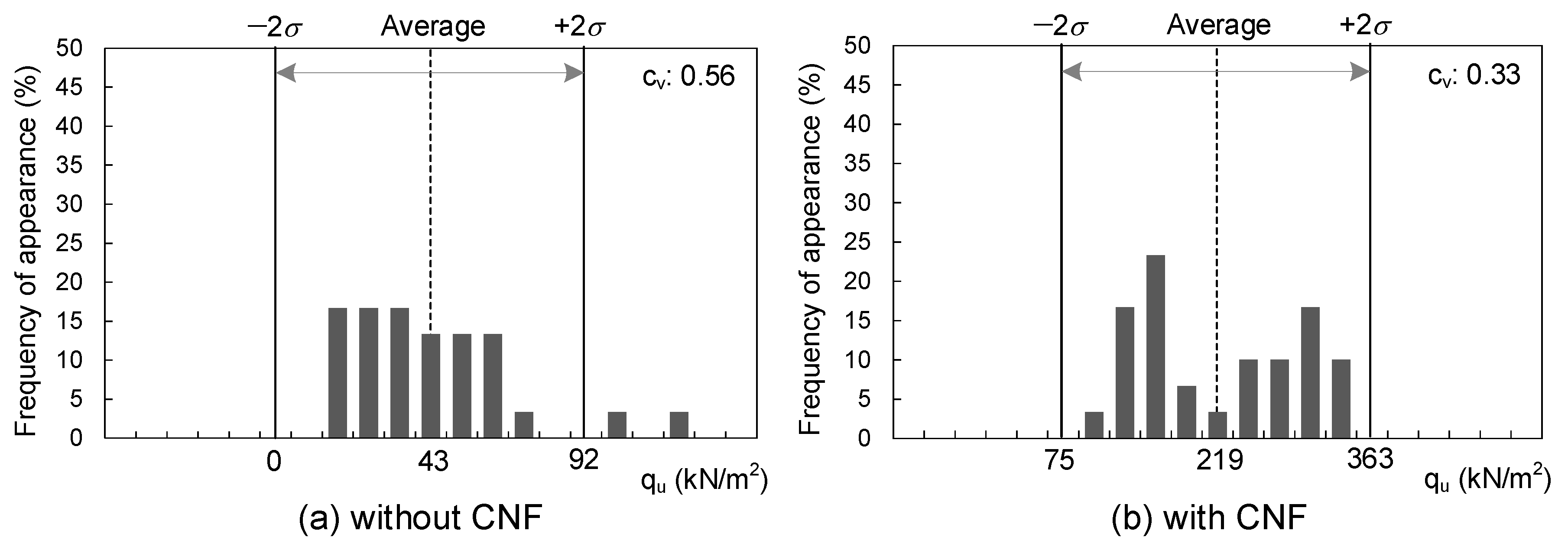
  • The effect of shortening the mixing time on the variation in the strength of CNF was investigated. It was observed that the cement tended to mix more evenly in the treated soil with CNF, and the average strength ratio at 28 days of age was 5.1 (strength with CNF/strength without CNF). The coefficients of variation of the strength and failure strain were also smaller when CNF was added. Reducing the variation in the strength of the treated soil has the advantage that the amount of cement added can be reduced, and unwanted high-strength treated soil is not produced.
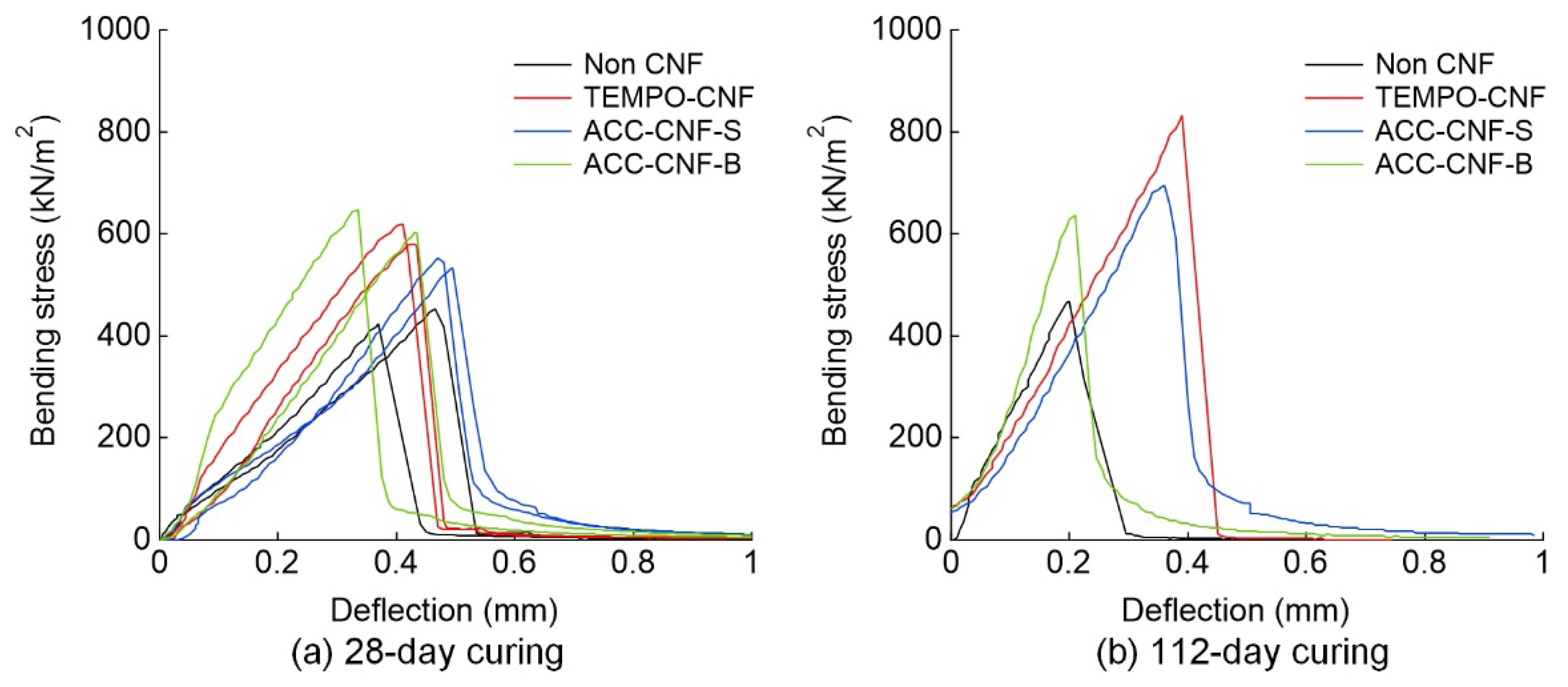
  • The addition of CNFs increased the flexural strength. This could be attributed to the increased tensile strength. Fibrous material appeared on the tensile fracture surface of the specimen to which CNF with low fibrillation was added. The low flexural and tensile strength is one of the drawbacks of cement-treated soil, and this problem could be solved.
  • The addition of CNF caused a slight change in permeability, although the number of tests in this study was not sufficient to determine a clear effect. It would suggest that the addition of CNF does not significantly change the permeability. The pore water conditions were estimated from the effluent, and it was found that the alkaline atmosphere was the same regardless of the presence or absence of CNF.
Thus, the addition of CNF to cement treatment had beneficial effects, depending on how it was used. This result is a quantum leap forward in encouraging the use of CNF in cement-treated soil. However, at present, the production volume of CNFs is limited, and their unit price is high. When CNFs are used in large quantities for civil engineering, the production volume will increase, and the price will decrease significantly. In practice, the price must be reduced before CNFs can be utilised. In addition, it is important to conduct trial mixing tests before the actual addition of CNF in the field, as the degree of effectiveness and properties may vary depending on the type of soil and the type of CNF. Moreover, if the chemical mechanism, although complex, can be clarified, it will be possible to add CNF more reliably to achieve the required effect. More detailed investigations of properties other than strength and permeability will be conducted in the future.

7. Patents

This paper includes the contents of the following patents applied in Japan: Manufacturing method of ground improvement soil and ground improvement method (JP2021011728A, JP2021011729A).

Author Contributions

Project administration and writing—original draft preparation, H.T.; data curation, S.O.; validation, H.A.; investigation, H.F.; investigation, Y.G.; validation, Y.M.; writing—review and editing, All authors. All authors have read and agreed to the published version of the manuscript.

Funding

This research received no external funding.

Institutional Review Board Statement

Not applicable.

Informed Consent Statement

Not applicable.

Acknowledgments

The authors would like to thank DKS Co. for the supply of TEMPO-CNFs and Marubeni Corporation and Chuetsu Pulp & Paper Co. for the supply of ACC-CNFs. In addition, the authors wish to thank Yosuke Tanaka (Toa Corporation) for his supports during the tests.

Conflicts of Interest

The authors declare no conflict of interest.

References

  1. Saito, T.; Nishiyama, Y.; Putaux, J.L.; Vignon, M.; Isogai, A. Homogeneous suspensions of individualized microfibrils from TEMPO-catalyzed oxidation of native cellulose. Biomacromolecules 2006, 7, 1687–1691. [Google Scholar] [CrossRef]
  2. Abe, K.; Iwamoto, S.; Yano, H. Obtaining cellulose nanofibers with a uniform width of 15 nm from wood. Biomacromolecules 2007, 8, 3276–3278. [Google Scholar] [CrossRef]
  3. Iwamoto, S.; Abe, K.; Yano, H. The effect of hemicelluloses on wood pulp nanofibrillation and nanofiber network characteristics. Biomacromolecules 2008, 9, 1022–1026. [Google Scholar] [CrossRef]
  4. Jiao, L.; Su, M.; Chen, L.; Wang, Y.; Zhu, H.; Dai, H. Natural cellulose nanofibers as sustainable enhancers in construction cement. PLoS ONE 2016, 11, e0168422. [Google Scholar] [CrossRef] [PubMed] [Green Version]
  5. Fu, T.; Moon, R.J.; Zavattieri, P.; Youngblood, J.; Weiss, W.J. Cellulose nanomaterials as additives for cementitious materials. Cellul. Reinf. Nanofibre Compos. 2017, 455–482. [Google Scholar] [CrossRef]
  6. Mejdoub, R.; Hammi, H.; Suñol, J.J.; Khitouni, M.; M’nif, A.; Boufi, S. Nanofibrillated cellulose as nanoreinforcement in Portland cement: Thermal, mechanical and microstructural properties. J. Compos. Mater. 2017, 51, 2491–2503. [Google Scholar] [CrossRef]
  7. Kitazume, M.; Terashi, M. The Deep Mixing Method; CRC Press/Balkema: London, UK, 2013; pp. 1–436. [Google Scholar] [CrossRef]
  8. Consoli, N.C.; Prietto, P.D.M.; Ulbrich, L.A. Influence of fiber and cement addition on behavior of sandy soil. J. Geotech. Geoenvironmental Eng. 1998, 124, 1211–1214. [Google Scholar] [CrossRef]
  9. Consoli, N.C.; Montardo, J.P.; Donato, M.; Prietto, P.D.M. Effect of material properties on the behaviour of sand-cement-fibre composites. Ground Improv. 2004, 8, 77–90. [Google Scholar] [CrossRef]
  10. Consoli, N.C.; de Moraes, R.R.; Festugato, L. Split tensile strength of monofilament polypropylene fiber-reinforced cemented sandy soils. Geosynth. Int. 2011, 18, 57–62. [Google Scholar] [CrossRef]
  11. Estabraph, A.R.; Namdar, P.; Javadi, A.A. Behavior of cement-stabilized clay reinforced with nylon fiber. Geosynth. Int. 2012, 19, 85–92. [Google Scholar] [CrossRef]
  12. Correia, A.A.S.; Oliveira, P.J.V.; Custodio, D.G. Effect of polypropylene fibres on the compressive and tensile strength of a soft soil, artificially stabilised with binders. Geotext. Geomembr. 2015, 43, 97–106. [Google Scholar] [CrossRef] [Green Version]
  13. Correia, A.A.S.; Oliveira, P.J.V.; Teles, J.M.N.P.C.; Pedro, A.M.G. Strength of a stabilised soil reinforced with steel fibres. Geotech. Eng. 2017, 170, 312–321. [Google Scholar] [CrossRef]
  14. Tang, Q.; Shi, P.; Zhang, Y.; Liu, W.; Chen, L. Strength and deformation properties of fiber and cement reinforced heavy metal-contaminated synthetic soils. Adv. Mater. Sci. Eng. 2019, 1–9. [Google Scholar] [CrossRef] [Green Version]
  15. Wang, W.; Zhang, C.; Guo, J.; Li, N.; Li, Y.; Zhou, H.; Liu, Y. Investigation on the triaxial mechanical characteristics of cement-treated subgrade soil admixed with polypropylene fiber. Appl. Sci. 2019, 9, 4557. [Google Scholar] [CrossRef] [Green Version]
  16. Correia, A.A.S.; Casaleiro, P.D.F.; Rasteiro, M.G.B.V. Applying multiwall carbon nanotubes for soil stabilization. Procedia Eng. 2015, 102, 1766–1775. [Google Scholar] [CrossRef] [Green Version]
  17. Correia, A.A.S.; Rasteiro, M.G. Nanotechnology applied to chemical soil stabilization. Procedia Eng. 2016, 143, 1252–1259. [Google Scholar] [CrossRef] [Green Version]
  18. Saito, T.; Kimura, S.; Nishiyama, Y.; Isogai, A. Cellulose nanofibers prepared by TEMPO-mediated oxidation of native cellulose. Biomacromolecules 2007, 8, 2485–2491. [Google Scholar] [CrossRef]
  19. Kondo, T.; Kose, R.; Naito, H.; Kasai, W. Aqueous counter collision using paired water jets as a novel means of preparing bio-nanofibers. Carbohydr. Polym. 2014, 112, 284–290. [Google Scholar] [CrossRef]
  20. Japanese Standards Association. JIS R 5201—Physical Testing Methods for Cement; Japanese Standards Association: Tokyo, Japan, 2019; pp. 1–107. [Google Scholar]
  21. Japanese Standards Association. JIS A 1216—Method for Unconfined Compression Test of Soils; Japanese Standards Association: Tokyo, Japan, 2020; pp. 1–16. (In Japanese) [Google Scholar]
  22. Japanese Geotechnical Society. JGS 0511—Method for unconfined compression test of soils. In Japanese Geotechnical Society—Laboratory Testing Standards of Geomaterials; Japanese Geotechnical Society: Tokyo, Japan, 2020; pp. 1–6. [Google Scholar]
  23. Terashi, M.; Tanaka, H.; Mitsumoto, T.; Niidome, Y.; Honma, S. Fundamental Properties of Lime and Cement Treated Soil, 2nd ed.; Port and Airport Research Institute: Kanagawa, Japan, 1980; Volume 19, pp. 33–62. (In Japanese)
  24. Kanda, T.; Tanaka, T.; Nohara, H.; Kubota, J. Development of high-performance fiber-reinforced soil cement. Annu. Rep. Kajima Tech. Res. Inst. 1999, 47, 79–85. (In Japanese) [Google Scholar]
  25. Namikawa, T.; Koseki, J. Evaluation of tensile strength of cement-treated sand based on several types of laboratory tests. Soils Found. 2007, 47, 657–674. [Google Scholar] [CrossRef] [Green Version]
  26. Coastal Development Institute Technology. The Premixing Method; CRC Press: London, UK, 2003; pp. 1–152. [Google Scholar] [CrossRef]
  27. Kitazume, M. The Pneumatic Flow Mixing Method; CRC Press/Balkema: London, UK, 2017; pp. 1–233. [Google Scholar] [CrossRef]
  28. Chew, S.H.; Kamruzzaman, A.H.M.; Lee, F.H. Physicochemical and Engineering behavior of cement treated clays. J. Geotech. Geoenvironmental Eng. 2004, 130, 696–706. [Google Scholar] [CrossRef]
  29. Takahashi, H.; Kitazume, M. Consolidation and permeability characteristics on cement treated clays from laboratory tests. In Proceedings of the International Symposium on Engineering Practice and Performance of Soft Deposits, Toyonaka, Japan, 2–4 June 2004; pp. 187–192. [Google Scholar]
  30. Vähäaho, I.; Kangas, H.; Takahashi, H.; Kitazume, M. Effect of permeability and stiffness of treated column on consolidation phenomenon of improved ground. In Proceedings of the 16th International Conference on Soil Mechanics and Geotechnical Engineering, Osaka, Japan, 12–16 September 2005; pp. 1269–1274. [Google Scholar]
  31. Terashi, M.; Tanaka, H.; Mitsumoto, T.; Honma, S.; Ohhashi, T. Fundamental Properties of Lime and Cement Treated, 3rd ed.; Port and Airport Research Institute: Kanagawa, Japan, 1983; Volume 22, pp. 69–96. (In Japanese)
  32. Kitazume, M.; Nakamura, T.; Terashi, M.; Ohishi, K. Laboratory tests on long-term strength of cement treated soil. In Proceedings of the 3rd International Conference on Grouting and Ground Treatment, New Orleans, LA, USA, 10–12 February 2003; Volume 1, pp. 586–597. [Google Scholar]
  33. Hayashi, H.; Nishikawa, J.; Ohishi, K.; Terashi, M. Field observation of long-term strength of cement treated soil. In Proceedings of the 3rd International Conference on Grouting and Ground treatment, New Orleans, LA, USA, 10–12 February 2003; Volume 1, pp. 598–609. [Google Scholar]
  34. Ikegami, M.; Ichiba, T.; Ohishi, K.; Terashi, M. Long-term strength change of cement treated soil at Daikoku Pier. In Proceedings of the Soft Ground Engineering in Coastal Areas, Yokusuka, Japan, 28–29 November 2002; pp. 241–246. [Google Scholar]
  35. Committee on Geocement. A study on long term stability of soil-cement columns improved by geocement. Cem. Concr. 2014, 804, 9–14. (In Japanese) [Google Scholar]
  36. Takahashi, H.; Morikawa, Y.; Fujii, N.; Kitazume, M. Thirty-seven-year investigation of quicklime-treated soil produced by deep mixing method. Ground Improv. 2018, 171, 135–147. [Google Scholar] [CrossRef] [Green Version]
  37. Takahashi, H.; Morikawa, Y.; Uemura, T. Trial tests to promote degradation of cement treated soil by percolation technique. In Proceedings of the Deep Mixing 2021, Online, 15–17 June 2021. [Google Scholar]
Figure 1. Mixture procedure for preparing specimens (Method 1).
Applsci 11 06425 g001
Figure 2. Appearance immediately after mixture by Method 1.
Applsci 11 06425 g002
Figure 3. Mixture procedure for preparing specimens (Method 2).
Applsci 11 06425 g003
Figure 4. Appearance immediately after mixture by Method 2.
Applsci 11 06425 g004
Figure 5. Relation between stress and strain in unconfined compression tests (Method 1).
Applsci 11 06425 g005
Figure 6. Time change of unconfined compressive strength (Method 1).
Applsci 11 06425 g006
Figure 7. Appearance of sheared surface (Method 1).
Applsci 11 06425 g007
Figure 8. Relation between bending stress and deflection in bending strength tests (Method 1).
Applsci 11 06425 g008
Figure 9. Appearance of tensile fracture surface (Method 1).
Applsci 11 06425 g009
Figure 10. Conceptual diagram of frequency distribution of strength and design strength.
Applsci 11 06425 g010
Figure 11. Relation between stress and strain in unconfined compression tests (Method 2).
Applsci 11 06425 g011
Figure 12. Appearance of sheared and trimmed surfaces (Method 2).
Applsci 11 06425 g012
Figure 13. Frequency of appearance of unconfined compressive strength.
Applsci 11 06425 g013
Figure 14. Frequency of appearance of failure strain.
Applsci 11 06425 g014
Figure 15. Schematic view of test apparatus.
Applsci 11 06425 g015
Figure 16. Chemical properties of drained water.
Applsci 11 06425 g016
Figure 17. SEM microphotograph of specimens.
Applsci 11 06425 g017
Table 1. Cellulose nanofibre used for tests.
TEMPO-CNFACC-CNF
IdentifierTEMPO-CNFTEMPO-CNFACC-CNF-SACC-CNF-B
Raw materialWood pulpWood pulpSoftwood pulpBamboo pulp
StateGelPowderGelGel
Content rate2.0%90%1.8% and 2.0%2.0%
Defibrating methodChemical fibrillationChemical fibrillationPhysical fibrillationPhysical fibrillation
Manufacturing methodTEMPO-mediated
oxidation
TEMPO-mediated
oxidation
Aqueous counter
collision
Aqueous counter
collision
Appearance Applsci 11 06425 i001 Applsci 11 06425 i002 Applsci 11 06425 i003 Applsci 11 06425 i004
Table 2. Physical properties of soils.
Kasaoka ClayKawasaki Clay
Soil particle density, rs (g/cm3)2.7002.671
Initial water content, wi (%)6.861.8
Grain sizeGravel fraction (2–75 mm) (%)0.00.0
Sand fraction (75 μm–2 mm) (%)1.113.1
Silt fraction (5–75 μm) (%)40.146.9
Clay fraction (<5 μm) (%)58.840.0
Fine fraction content, Fc (%)98.986.9
Liquid limit, wL (%)62.141.0
Plastic limit, wP (%)20.623.1
Plasticity index, IP41.517.9
Table 3. Mix proportion of cement, CNF, water, and soil in Method 1: (a) Treated soil without CNF; (b) Treated soil with TEMPO-CNF (Gel); (c) Treated soil with ACC-CNF-S; (d) Treated soil with ACC-CNF-B.
(a)Amounts of ComponentCNF
Addition Rate (%)
Cement Addition
(kg/m3)
Soil (Kasaoka Clay)WaterCement
(Ordinary Portland)
CNF –No Addition–Total
TotalSoil
Particle
WaterTotalSolid ContentWater
g7697254565510000015250.0100.0
g/cm3-2.701.001.003.16-1.51.01.52
cm331326845655320001000
(b)Amounts of ComponentCNF
Addition Rate (%)
Cement Addition
(kg/m3)
Soil (Kasaoka Clay)WaterCement
(Ordinary Portland)
CNF (TEMPO-CNF)Total
TotalSoil
Particle
WaterTotalSolid ContentWater
g769725453001003637.2535515321.099.5
g/cm3-2.701.001.003.16-1.51.01.52
cm3313268453003236053551005
(c)Amounts of ComponentCNF
Addition Rate (%)
Cement Addition
(kg/m3)
Soil (Kasaoka Clay)WaterCement
(Ordinary Portland)
CNF (ACC-CNF-S)Total
TotalSoil
Particle
WaterTotalSolid ContentWater
g769725452601004037.2539615321.099.5
g/cm3-2.701.001.003.16-1.51.01.52
cm3313268452603240053961005
(d)Amounts of ComponentCNF
Addition Rate (%)
Cement Addition
(kg/m3)
Soil (Kasaoka Clay)WaterCement
(Ordinary Portland)
CNF (ACC-CNF-B)Total
TotalSoil
Particle
WaterTotalSolid ContentWater
g769725453001003637.2535515321.099.5
g/cm3-2.701.001.003.16-1.51.01.52
cm3313268453003236053551005
Table 4. Mix proportion of cement, CNF, water, and soil in Method 2 for evaluating variability: (a) Treated soil without CNF; (b) Treated soil with TEMPO-CNF (Powder).
(a)Amounts of ComponentCNF
Addition Rate (%)
Cement Addition
(kg/m3)
Soil (Kawasaki Clay)WaterCement
(Blast Furnace t. B)
CNF –No Addition–Total
TotalSoil
Particle
WaterTotalSolid ContentWater
g1687103065705000017370.047.9
g/cm3-2.6711.0231.003.04-1.51.01.662
cm310283866420160001044
(b)Amounts of ComponentCNF
Addition Rate (%)
Cement Addition
(kg/m3)
Soil (Kawasaki Clay)WaterCement
(Blast Furnace t. B)
CNF (TEMPO-CNF)Total
TotalSoil
Particle
WaterTotalSolid ContentWater
g1686103065605011.4310.301.1317471.047.6
g/cm3-2.6711.0231.003.04-1.51.01.662
cm310273866410168.006.871.131051
Table 5. Mix proportion of cement, CNF, water, and soil in Method 2 for evaluating permeability: (a) Treated soil without CNF; (b) Treated soil with TEMPO-CNF (Powder); (c) Treated soil with ACC-CNF-S (Gel).
(a)Amounts of ComponentCNF
Addition Rate (%)
Cement Addition
(kg/m3)
Soil (Kawasaki Clay)WaterCement
(Early Strength)
CNF –No Addition–Total
TotalSoil
Particle
WaterTotalSolid ContentWater
g2000123776332512400024490.078.6
g/cm3-2.6711.0231.003.14-1.51.01.556
cm31209463746325390001574
(b)Amounts of ComponentCNF
Addition Rate (%)
Cement Addition
(kg/m3)
Soil (Kawasaki Clay)WaterCement
(Early Strength)
CNF (TEMPO-CNF)Total
TotalSoil
Particle
WaterTotalSolid ContentWater
g2000123776332412413.7412.371.3724611.078.2
g/cm3-2.6711.0231.003.14-1.51.01.556
cm31209463746324399.628.251.371582
(c)Amounts of ComponentCNF
Addition Rate (%)
Cement Addition
(kg/m3)
Soil (Kawasaki Clay)WaterCement
(Early Strength)
CNF (ACC-CNF-S)Total
TotalSoil
Particle
WaterTotalSolid ContentWater
g200012377630124331.96.64325.324560.578.4
g/cm3-2.6711.0231.003.14-1.51.01.556
cm31209463746039329.74.43325.31578
Publisher’s Note: MDPI stays neutral with regard to jurisdictional claims in published maps and institutional affiliations.

