Article

Effect of Vibration on Emergency Braking Tribological Behaviors of Brake Shoe of Deep Coal Mine Hoist

1
School of Mechatronic Engineering, China University of Mining and Technology, Daxue Road #1, Xuzhou 221116, China
2
Jiangsu Province and Education Ministry Co-Sponsored Collaborative Innovation Center of Intelligent Mining Equipment, China University of Mining and Technology, Xuzhou 221116, China
3
Institute of Research and Development, Duy Tan University, 03 Quang Trung, Da Nang 550000, Vietnam
4
Soete Laboratory, Faculty of Engineering and Architecture, Ghent University, Technologiepark Zwijnaarde 903, B-9052 Zwijnaarde, Belgium
*
Author to whom correspondence should be addressed.
Appl. Sci. 2021, 11(14), 6441; https://doi.org/10.3390/app11146441
Submission received: 14 June 2021 / Revised: 1 July 2021 / Accepted: 1 July 2021 / Published: 13 July 2021

Abstract

:
The effects of vibration on the emergency braking tribological behaviors of the brake shoe of a deep coal mine hoist were investigated in this study. The thermal, frictional and mechanical parameters of the brake shoe were obtained. The vibration characteristics of the brake shoe during emergency braking were investigated, employing multibody dynamics analysis. The effect of vibration on the emergency braking tribological behaviors (temperature and stress distributions) of brake interfaces was explored using the finite element method. The self-made tribo-brake test rig of a brake shoe was employed to reveal the friction deterioration behaviors of the brake shoe during emergency braking. The results show obvious vibrations of all brake shoes along the direction of positive braking pressure during emergency braking. The vibration causes increases in the equivalent Von Mises stress and temperature at the contact interfaces between the brake disc and the brake shoe as compared to the case of ignoring the vibration. Along the rotation direction of the brake disc, the equivalent stress and temperature of the brake disc surface present three overall rapid increases, as well as two slight decreases during emergency braking. As compared to cyclic emergency braking, continuous emergency braking exhibits more obvious tribological degradation of the brake shoe, attributed to enhanced vibration. The wear loss of the brake shoe increases with increasing emergency braking cycles and continuous emergency braking time.

1. Introduction

In China, kilometer-deep coal reserves account for 47% of proven coal resources [1]. Mining deep coal resources with a buried depth greater than 1500 m is a major development strategy in China. The hoisting mechanism for a 1.5-km-deep coal mine exhibits characteristics of large inertia and vibration as compared to that of a 1-km-deep coal mine [2,3,4]. When safety hazards, such as overspeed and the loss of control of the motor (when the motor continues to provide traction torque when it should be shut down at the end of hoisting), occur in the multi-rope friction hoist of a 1.5-km-deep coal mine [2], emergency braking between the brake disc and the brake shoe, with conditions involving high speed and high specific pressure and vibration [3,5,6], easily causes emergency braking tribological behaviors (uneven distributions of thermal stress and friction deterioration) of the brake shoe. Therefore, the failure of emergency braking in the brake shoe greatly affects the braking safety and the reliability of the hoist, and even causes braking impact, rope skidding and overwinding accidents, which causes serious and deadly accidents, such as well destruction in the coal mine and human death. Therefore, it is of great significance to investigate the emergency braking tribological behaviors of a brake shoe under the effects of vibration in order to improve the braking safety and reliability of a 1.5-km-deep coal mine hoist.
Several scholars have carried out studies on the friction and wear behaviors of brake shoes during emergency braking ignoring vibration. Wang et al. [7] discussed the effect of a temperature rise on the coefficient of friction between the brake disc and the brake shoe. Bao et al. [8] explored the effect of braking pressure on the friction and wear properties of the brake shoe. Olesiak et al. [9] analyzed the effect of the temperature field distribution on the coefficient of friction and the wear rate of the brake shoe. Zhu et al. [10,11] studied the effects of braking parameters on the frictional catastrophe behaviors of the brake shoe. Pyryev and Yevtushenko [12] discussed the effect of the friction material composition on temperature and wear characteristics at the brake shoe surface. Wang et al. [1] explored the effects of initial brake speed, braking specific pressure and brake shoe material on the coefficient of friction of brake shoe material during one-cycle emergency braking. According to the thermo-stress fields and vibration characteristics of a brake shoe during emergency braking ignoring vibration, Olesiak et al. [9] investigated the temperature field distribution of the brake shoe. Wang et al. [3] studied the effects of hoisting on the equivalent von Mises stress and temperature fields of a brake shoe. Wang et al. [13] explored the effects of braking parameters on thermo-stress fields and flutter characteristics, respectively, without coupling them together. However, emergency braking tribological behaviors (uneven distributions of thermal stress and friction deterioration) of brake shoes under the vibration effect for 1.5-km-deep coal mine hoists have not yet been reported.
In this study, Section 1 exhibits the performance parameters and emergency braking test method for the brake shoe. In Section 2, the vibration behaviors of the brake shoe during emergency braking are presented. Based on the results presented in Section 1 and Section 2, the effect of vibration on the emergency braking tribological behaviors of brake interfaces is investigated in Section 3. In Section 4, the friction deterioration behaviors of the brake shoe during emergency braking are discussed.

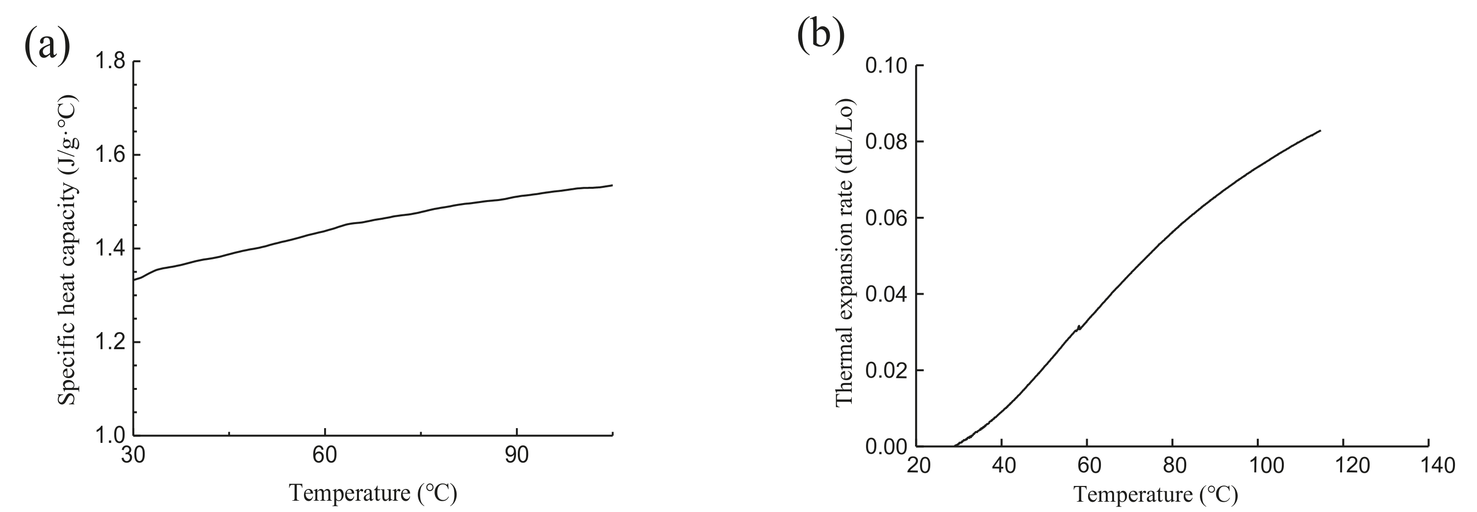
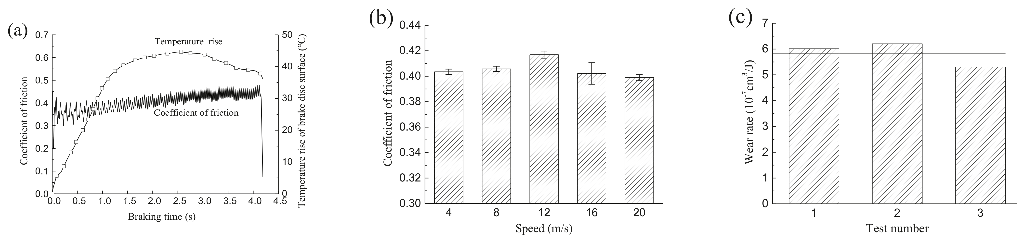
2. Performance Parameters of the Brake Shoe

The brake shoe has the density of 1788 g/cm3, an elastic modulus of 1031 MPa and Poisson’s ratio of 0.23. The DSC differential scanning calorimeter is employed to measure the specific heat capacity of the brake shoe, and the evolution curve of specific heat capacity versus temperature is shown in Figure 1a. Figure 1a shows that the specific heat capacity of the brake shoe increases gradually with increasing temperature with the variation range of 1.33–1.54 J/(g·°C). A Netzsch TMA402 thermal mechanical analyzer was employed to measure the evolution law of the thermal expansion rate of a brake shoe specimen with temperature, as shown in Figure 1b. Figure 1b shows that the thermal expansion rate of the brake shoe specimen increases with increasing temperature. The slopes of thermal expansion rate curve at different stages correspond to the thermal expansion coefficient of the brake shoe specimen within temperature ranges as shown in Table 1. The Hot Disk thermal conductivity meter was employed to measure the thermal conductivities of brake shoe specimens. The coefficients of thermal conductivity at the temperatures of 20·°C, 45·°C, 70·°C and 100·°C are 1.63 W/mK, 1.65 W/mK, 1.68 W/mK and 1.71 W/mK, respectively.
The tribo-brake test rig for brake shoes [1] was employed to conduct emergency braking tests of a brake shoe with distinct emergency brake cycles and braking time. The testing parameters of the test rig were as follows: moment of inertia of the system of 5.67 kg·m2, two friction surfaces, maximum spindle speed of 1470 r/min, average friction radius of brake disc of 150 mm, speed of 20 m/s at the average friction radius, friction area of the brake shoe of 6.25 × 10⁻³ m2, brake deceleration of 3.8 m/s2 and specific braking pressure of 2 MPa. In this system, the motor drove the flywheel (simulating the moment of inertia of the mine hoist) and the brake disc to rotate, and the hydraulic system applied the constant braking force between the brake disc and the brake shoe to realize the emergency braking. Therefore, the friction and relative sliding between the brake disc and the brake shoe caused deterioration characteristics of wear and fatigue of the brake shoe. A three-dimensional force transducer was used to measure the normal force and friction force along the sliding direction between the brake disc and the brake shoe during emergency braking in order to obtain the coefficient of friction. The infrared temperature transducer was employed to measure the temperature at the sliding-out side of the contact region of the brake disc during emergency braking. The self-made tribo-brake test rig of the brake shoe was used to conduct emergency braking wear tests of the brake shoe, and the equation used to calculate the wear rate of brake shoe k is described as Equation (1) [14]. A VXH-6000 high-precision digital microscope system was employed to observe the wear morphology and three-dimensional wear scar of the brake shoe after the test in order to reveal the deterioration mechanism.
k = V n · Q = S · Δ l n · Q = Δ l e
where V is the wear volume of the brake shoe, n is the emergency braking cycles, Q is the system energy consumed during emergency braking, S is the friction area of the brake shoe, Δl is the thickness difference of the brake shoe before and after the test, and e is the braking energy density (system energy consumed per unit area of the brake shoe [14]).
The coefficient of friction between the brake disc and the brake shoe and the temperature rise of the brake disc surface during the emergency braking test are shown in Figure 2a. Figure 2a shows the rapid increase in the coefficient of friction at the initial stage, then the overall fluctuating upward trend and finally the rapid decrease at the end of emergency braking. The average coefficient of friction between the brake disc and the brake shoe during emergency braking is approximately 0.4. During emergency braking, the temperature rise of the brake disc presents an increase at first and then a decrease, and the maximum temperature rise at the brake disc surface is approximately 44.7 °C. Figure 2b exhibits the average coefficient of friction between the brake disc and the brake shoe during the emergency braking in cases of distinct speeds, corresponding to the fluctuating curve of the coefficient of friction in Figure 2a. In each speed case, we conducted three emergency braking tests and easily obtained the error bar in Figure 2b using the standard deviation method. Figure 2b shows that there was an increase at first and then a decrease in the average coefficient with increasing speed at the average friction radius of the brake disc. The coefficient of friction between the brake disc and the brake shoe reached the maximum value of 0.42 at the speed of 12 m/s. Figure 2c shows that the average wear rate of the brake shoe during three emergency braking tests was 5.840 × 10⁻⁷ cm3/J with the standard deviation of 0.473.

3. Vibration Behaviors of the Brake Shoe during Emergency Braking

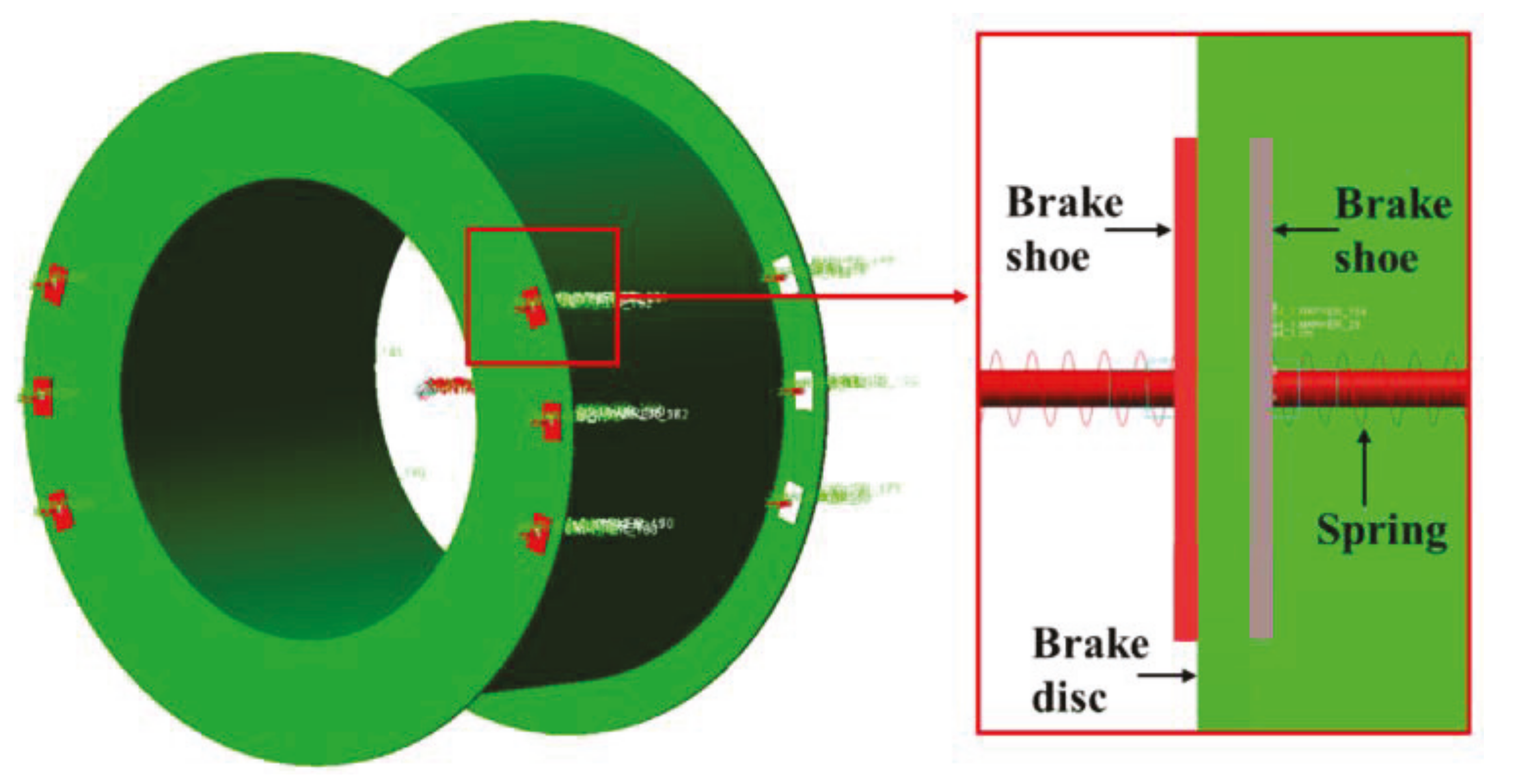
3.1. Dynamic Model of the Brake Shoe during Emergency Braking

Based on parameters of a multi-rope friction hoisting system (Table 1 in [3]) and the evolution curves of the hoisting speed of the container and emergency braking deceleration (Figure 2 in [3]), and according to the special hoisting parameters of a 1.5-km-deep coal mine (hoisting height of 1500 m, initial vertical rope length of 1520 m at the lifting side and maximum hoisting speed of 20 m/s), dynamic analyses of the hoisting system during emergency braking were conducted, employing the multibody dynamics software Adams. Due to the complexity of direct modeling and the low efficiency of calculation in the case of a 1.5-km-long hoisting rope, a dynamic model of the brake disc and brake shoes (Figure 3) was established in order to simplify the calculation. In Figure 3, the red and gray colors indicate the brake shoes located at both sides of the brake disc; the brake disc and drum are shown in green colors, and an expanded view of the green-colored area is shown on the right side. In the dynamic model, the torque, induced by the difference in hoisting rope tensions at both sides during emergency braking, is applied to the drum (Figure 3). Two brake discs are located at both sides of the drum, and six pairs of brake shoes are symmetrically arranged at both sides of each brake disc. The brake disc has an average friction radius of 5 m, an outer diameter of 5.4 m and an inner diameter of 4.6 m; the brake shoe has a length of 380 mm, a width of 244 mm and a frictional area of 0.09272 m2; the thicknesses of the brake disc and the brake shoe are 140 mm and 30 mm, respectively. In the dynamic model, the 16 Mn material was applied to the brake disc through the Adams material library, and the material parameters of the brake shoe can be found in Section 1. Sliding pairs were set between 12 pairs of brake shoes and the earth; the revolute pair was set between the drum and the earth. In order to simulate the mechanical characteristics of brake shoes, connecting springs were set between 12 pairs of brake shoes and the earth. According to coal mine safety regulations in China, the stiffness and damping ratio of the spring are set to be 5.66 kN/mm and 0.125 [15,16], respectively; the normal braking force Fn was applied to the spring in order to simulate the specific braking pressure. Fn is equal to the product of the specific braking pressure P0 and the friction area of the brake shoe A. The contact algorithm based on the collision function and the Coulomb friction model were employed between the brake disc and the brake shoe. Static and dynamic coefficients of friction are set to be 0.6 and 0.4, respectively. The dynamic torque f(t), described in Section 3, was applied to the drum.

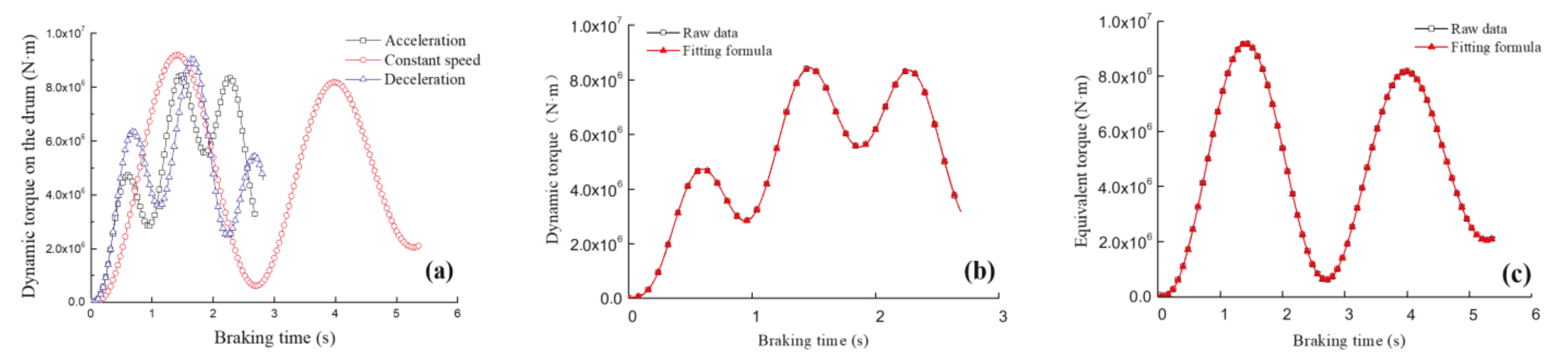
3.2. Dynamic Torque during Emergency Braking

In the hoisting system, equivalent masses of various components, i.e., the hoisting container, hoisting rope, tail rope, drum, hoisting sheave and motor rotor, are all shifted to the drum. During the emergency braking, the dynamic tensions of the hoisting rope at the hoisting and lowering sides cause dynamic torque to be exerted on the drum [3,13,17,18]. The dynamic tensions of the hoisting rope at the winding-in (hoisting) and winding-out (lowering) sides during emergency braking, i.e., S1 and S2, are expressed as Equations (2) and (3) [3,17,18]. The dynamic torque exerted on the drum due to the equivalent mass and dynamic tension of the hoisting rope is expressed as Equation (4) [3,13]. Therefore, the evolutions of the dynamic tensions of the hoisting rope at the lifting and lowering sides during emergency braking at the hoisting stages of acceleration, constant speed and deceleration can be obtained using Equations (2) and (3). The evolution characteristics of dynamic torque Td exerted on the drum during emergency braking at distinct hoisting stages can be obtained by substituting the dynamic tensions of the hoisting rope into Equation (4).
S 1 = a g · F 1 · ( 1   1 + 0.72 a 1 + a · c o s ( ω · t + ψ ) ) + F 1
S 2 = a g · F 2 · ( 1 1 + 0.72 a 1 + a · c o s ( ω · t + ψ ) ) + F 2
T d = ( m · a ( S 1 S 2 ) ) · R
where a is the emergency braking deceleration, i.e., a = 3.8 m/s2; g is the acceleration of gravity, i.e., g = 9.8 m/s2; F1 and F2 are the static tensions of the hoisting rope at the winding-in (hoisting) and winding-out (lowering) sides of the drum, respectively; t is the emergency braking time; s, ω is the angular velocity of drum during emergency braking, i.e., ω = 1 l α · E · A 1 + α 3 ρ [3,19,20], rad/s; ψ is the drum phase during emergency braking, i.e., ψ = arctan α 1 + α 3 [3,19,20]; and ∑m is the total equivalent mass of the hoisting system, in kg. In the total equivalent mass of the hoisting system, we mainly focus on the masses of the drum, hoisting sheave and motor rotor. In equations of ω and ψ, α is the ratio of the hoisting rope mass to the terminal mass (the sum of the masses of the container, effective load and tail rope); E is the elastic modulus of hoisting rope; A is the cross-section area of the hoisting rope; ρ is the mass of the hoisting rope per meter, kg/m; and l is the vertical rope length of the hoisting rope during emergency braking (assuming a constant vertical rope length of the hoisting rope at both sides during emergency braking for simplicity, due to the small effect of vertical rope lengths on the dynamic tension of the hoisting rope during emergency braking).
Figure 4a shows the dynamic evolution characteristics of the torque during emergency braking in cases of different hoisting stages corresponding to the times 13.33 s, 50.83 s and 88.33 s, respectively. In order to apply the dynamic torque to the drum in the dynamic model conveniently, the curve fitting method was employed to obtain evolution formulas of dynamic torque during emergency braking in cases of distinct hoisting stages (Figure 4b,c). Evolution formulas of dynamic torque mainly present forms of Equations (2) and (3) with fitting coefficients as shown in Table 2. We know that the dynamic torque exhibits combinations of sine and cosine forms, and is correlated with the ω and t according to Equations (2) to (4), and thus the Formulas (5) and (6) were fitted using Origin software. Therefore, the evolution formulas of dynamic torque during emergency braking were input into the torque module in the dynamic model.
T d = a 0 + i = 1 5 ( a i · c o s ( i · t · ω ) + b i · s i n ( i · t · ω ) )
T d = i = 1 5 ( a i · s i n ( b i · t + c i ) )
where Td is the dynamic torque; t is the brake time; ω is the angular velocity of drum during emergency braking; and a0, ai, bi and ci are fitting coefficients.

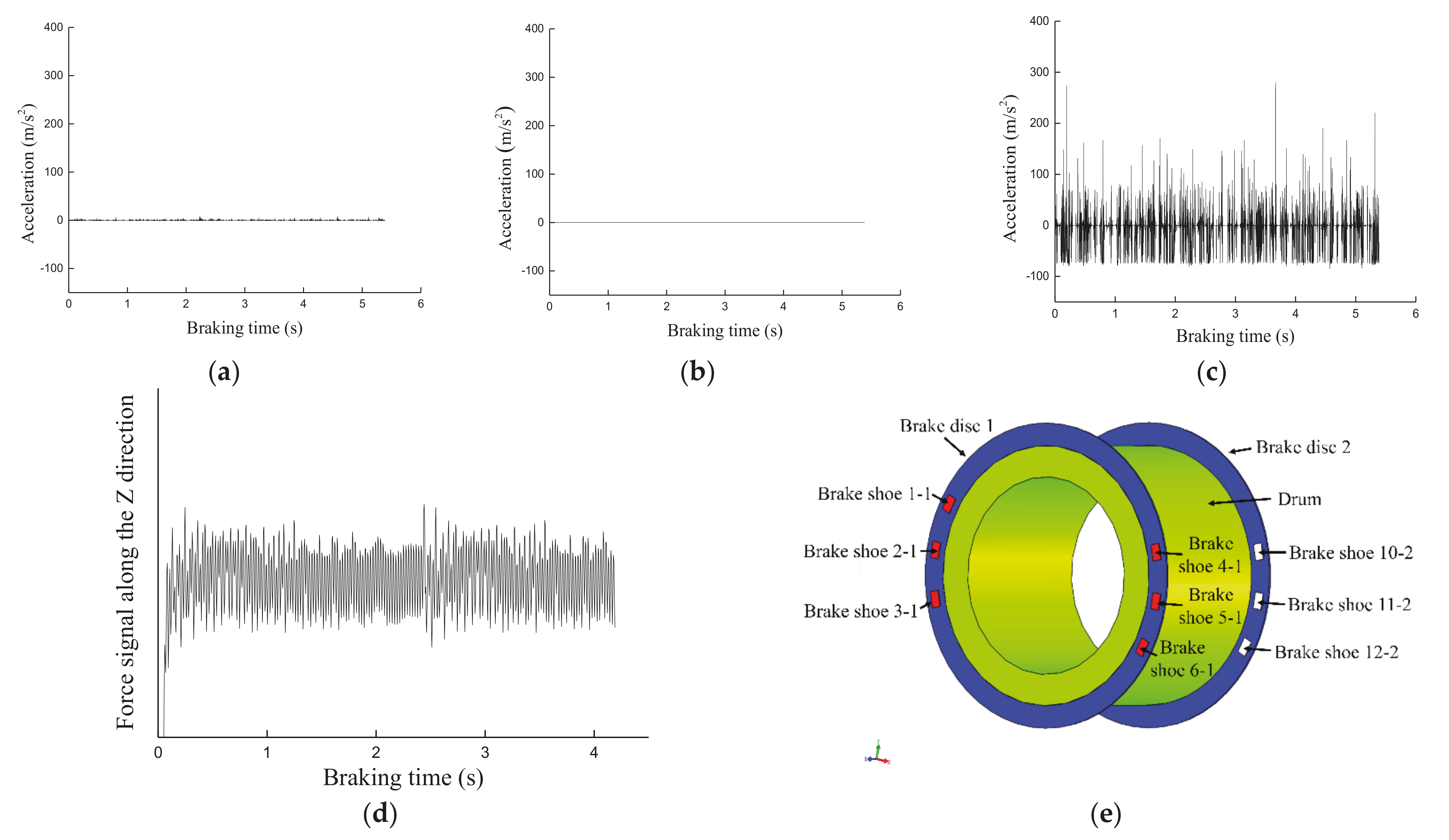
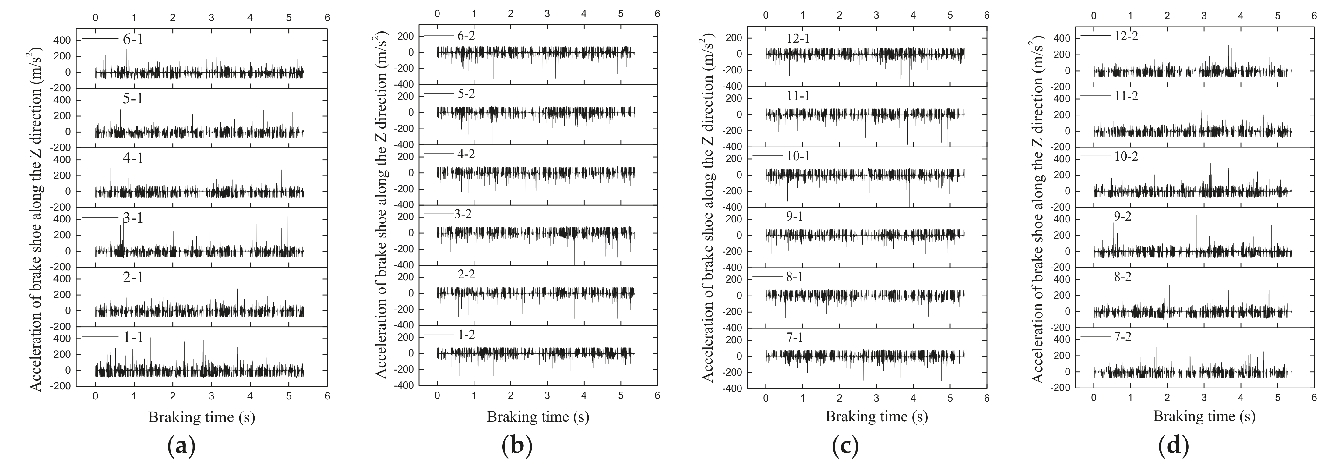
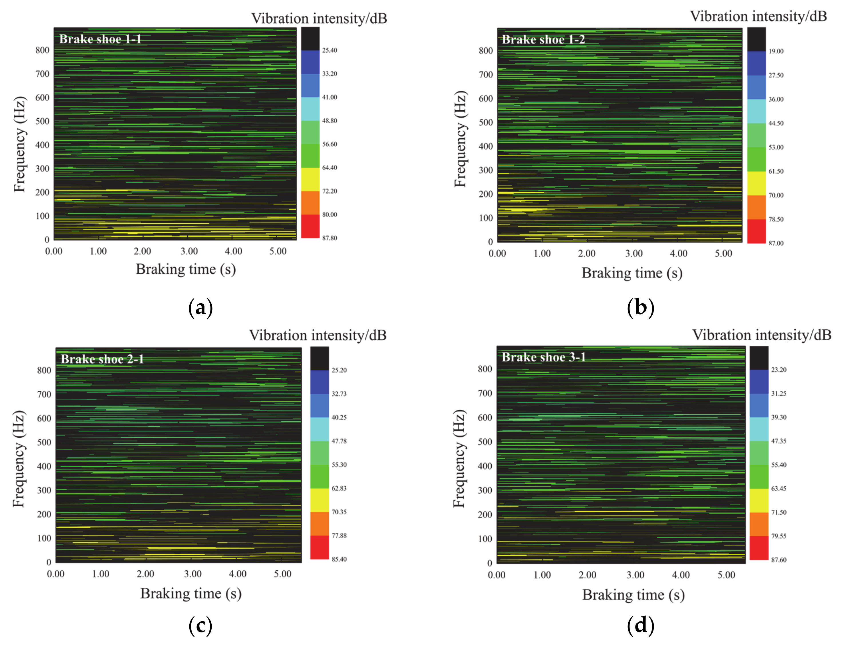
3.3. Vibration Characteristics of the Brake Shoe during Emergency Braking

The vibration acceleration is used to evaluate vibration characteristics of brake shoe. Figure 5a–c show the obvious vibration along Z direction of the brake shoe (the direction of braking pressure) and unobvious vibrations in other directions, which is consistent with the evolution characteristics of the fluctuating normal pressure of the brake shoe during emergency braking (Figure 5d) obtained using the self-made friction braking test rig and which validates the dynamic model of the disc brake based on Adams. In order to quantitatively reveal the vibration characteristics of the brake shoe at different locations during emergency braking, brake disc 1 contacts brake shoes 1–6, and brake disc 2 contacts brake shoes 7–12; the inner and outer surfaces of the brake disc correspond to brake shoes i-2 and i-1, respectively (Figure 5e).
Figure 6 shows that the 12 pairs of brake shoes all present obvious vibration phenomenon along the normal pressure direction between the brake disc and the brake shoe during emergency braking. The vibration accelerations of various brake shoes fluctuate in the range of −80 m/s2–80 m/s2, and tend to be zero at some moments due to stick-slip vibration between the brake disc and the brake shoe. The time-frequency distribution of the brake shoe can be obtained through the STFT transformation of the vibration acceleration of the brake shoe. It can be seen that the low-frequency vibration intensity is larger than the high-frequency vibration intensity in cases of various brake shoes; the maximum vibration frequency is greater than 800 Hz. Figure 7a shows the relatively large vibration intensity of the brake shoe in the vibration frequency range of 0–200 Hz, the sparse vibration distribution but high vibration intensity in the vibration frequency range of 200–400 Hz, and the relatively uniform vibration distribution but relatively low vibration intensity in the vibration frequency range of 400–800 Hz. Figure 7b shows that the vibration intensity is larger in the middle stage of emergency braking as compared to the early and late stages of emergency braking; the vibration frequency exhibits a wider range of vibration frequency in the middle stage of emergency braking as compared to early and late stages of emergency braking. Comparisons of Figure 7a,b show the wider frequency range corresponding to the high vibration intensity of brake shoe 1-1. Figure 7a,c,d show similar distribution laws of vibration frequencies of three brake shoes during emergency braking and exhibit the highest vibration intensity in the vibration frequency range of 0–200 Hz. Brake shoes 1-3 all present a low distribution density of high vibration intensity in the vibration frequency range of 0–200 Hz and an increase in the distribution density of vibration intensity in the vibration frequency range of 300–800 Hz, which may be attributed to the effect of the superposition of vibrations along the rotation direction of the brake disc and the more active high frequency vibration.

4. Effect of Vibration on Emergency Braking Tribological Behaviors of Brake Interfaces

During emergency braking in a 1.5-km-deep coal mine hoist, the vibration affects the emergency braking tribological behaviors of brake interfaces (temperature and stress distributions). Therefore, according to vibration characteristics of the brake shoe presented in Section 2, the emergency braking model of brake shoe under vibration can be established.

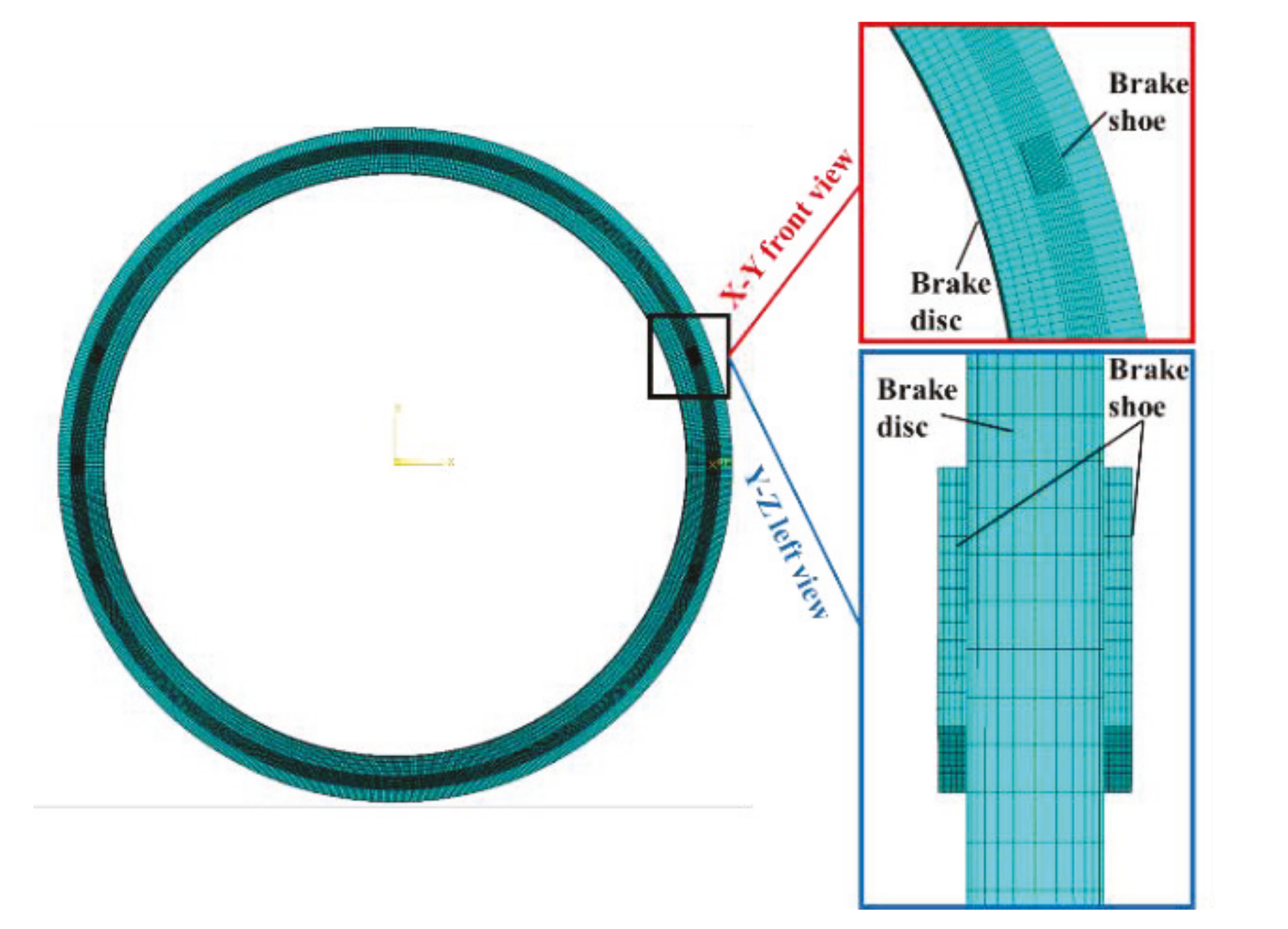
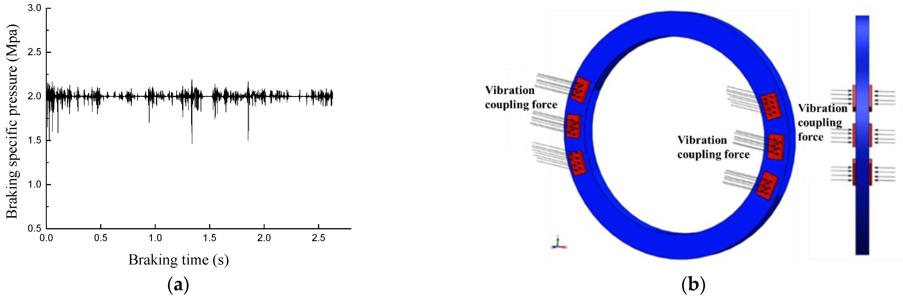
4.1. Emergency Braking Model of Brake Shoe under Vibration

An emergency braking finite element model of a brake shoe under vibration (Figure 8) was established, employing the finite element software ABAQUS, according to Figure 3. The dimensions of the brake disc and the brake shoe, and the material parameters of the brake shoe can be found in Section 2 and Section 1, respectively. The brake disc made of 16 Mn material has a density of 7850 kg·m−3, elastic modulus of 2.2 × 10⁵ MPa, specific heat capacity of 460 J·(kg·K)−1, Poisson’s ratio of 0.3, thermal expansion coefficient of 1.2 × 10⁻⁵ K and thermal conductivity of 58 W·(m·K)−1 [19]. The eight-node hexahedral element (C3D8RT) was employed to mesh the finite element model. The meshes at the contact regions of the brake disc and brake shoe were refined. The finite element model has 75,800 elements and 93,656 nodes, a full Newton solver, and uses a linear interpolation method; the brake disc and brake shoe have the smallest mesh sizes of 18 mm × 48 mm × 4 mm and 11 mm × 19 mm × 6 mm, respectively. The master–slave surface-to-surface contact method and the finite sliding contact state tracking method were employed between the brake disc and brake shoe. The bilinear Coulomb friction model was adopted between the brake disc and the brake shoe in the finite element model. The average coefficient of friction between the brake disc and the brake shoe in the stabilized stage during emergency braking was chosen to be 0.4, according to the results presented in Section 1. All degrees of freedom of the brake shoe except the Z direction were constrained, which indicated that the brake shoe was allowed to move along the direction of normal pressure between the brake disc and the brake shoe. Reference nodes were set at the centers of the brake discs in order to couple the nodes of the corresponding brake disc surfaces. Therefore, the degree of freedom of the reference node was constrained to constrain the degrees of freedom of the surface nodes of the brake disc. The degrees of freedom were constrained except for the degree of freedom of rotation in the Z direction (RZ), which allowed for the rotation of the brake disc along its axis. The initial temperature of the brake disc and all brake shoes was set to be 20 °C [3,13]. The convective heat transfer coefficient, obtained via Equation (7) [20], was applied to brake disc surface due to the convective heat transfer between the brake disc surface and the air during emergency braking. The speed and emergency braking deceleration of the brake disc were set through reference nodes. According to the vibration acceleration of the brake shoe during emergency braking in Section 3.3 and Equation (8), the obtained dynamic evolution of the braking force of the brake shoe was used as the vibration boundary condition to the brake shoe. Figure 9 shows the evolution curve of the specific braking pressure and the application of braking force.
h = 0.7 λ a d a R e 0.55 , R e 2.4 × 10 5 0.04 λ a d a R e 0.8 , R e 2.4 × 10 5
where Re is the Reynold number, R e = v a ρ a d a 3.6 μ a , λa is the thermal conductivity and da is the outer diameter of the brake disc. In the equation of Re, va is the rotational speed, ρa is the fluid density and μa is the fluid viscosity.
P ( t ) = F + m · a ( t ) S
where P(t) is the specific braking pressure, F is the braking force provided by the braking system, m is the mass of the brake shoe, a ( t ) is the vibration acceleration and S is the frictional area of the brake shoe.

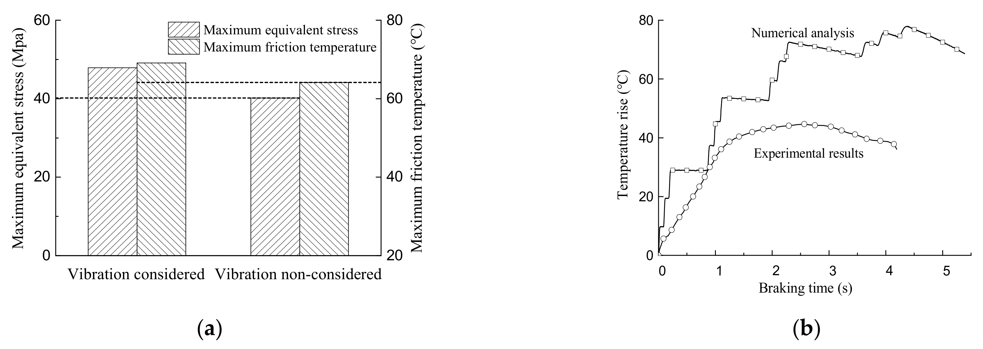
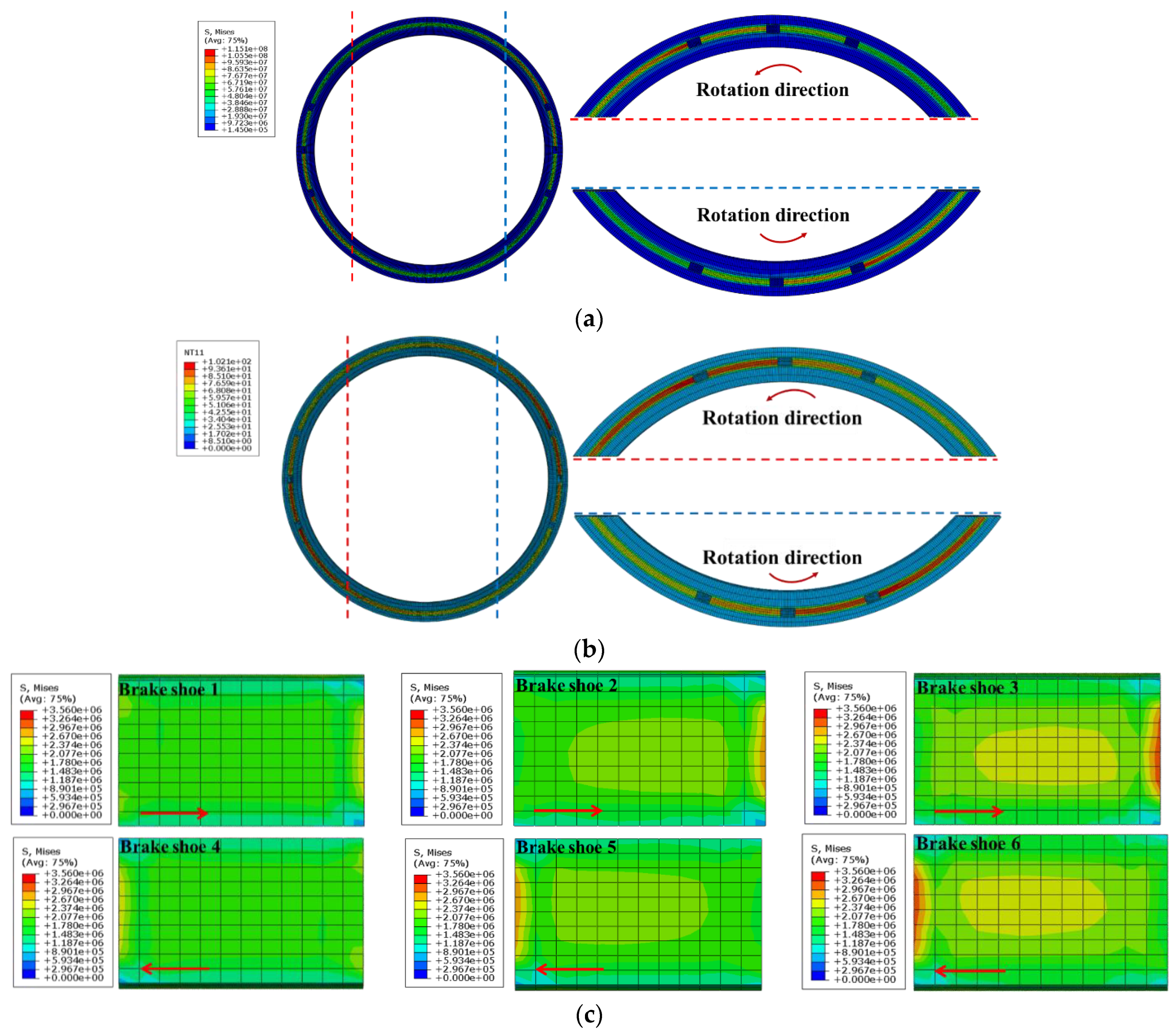
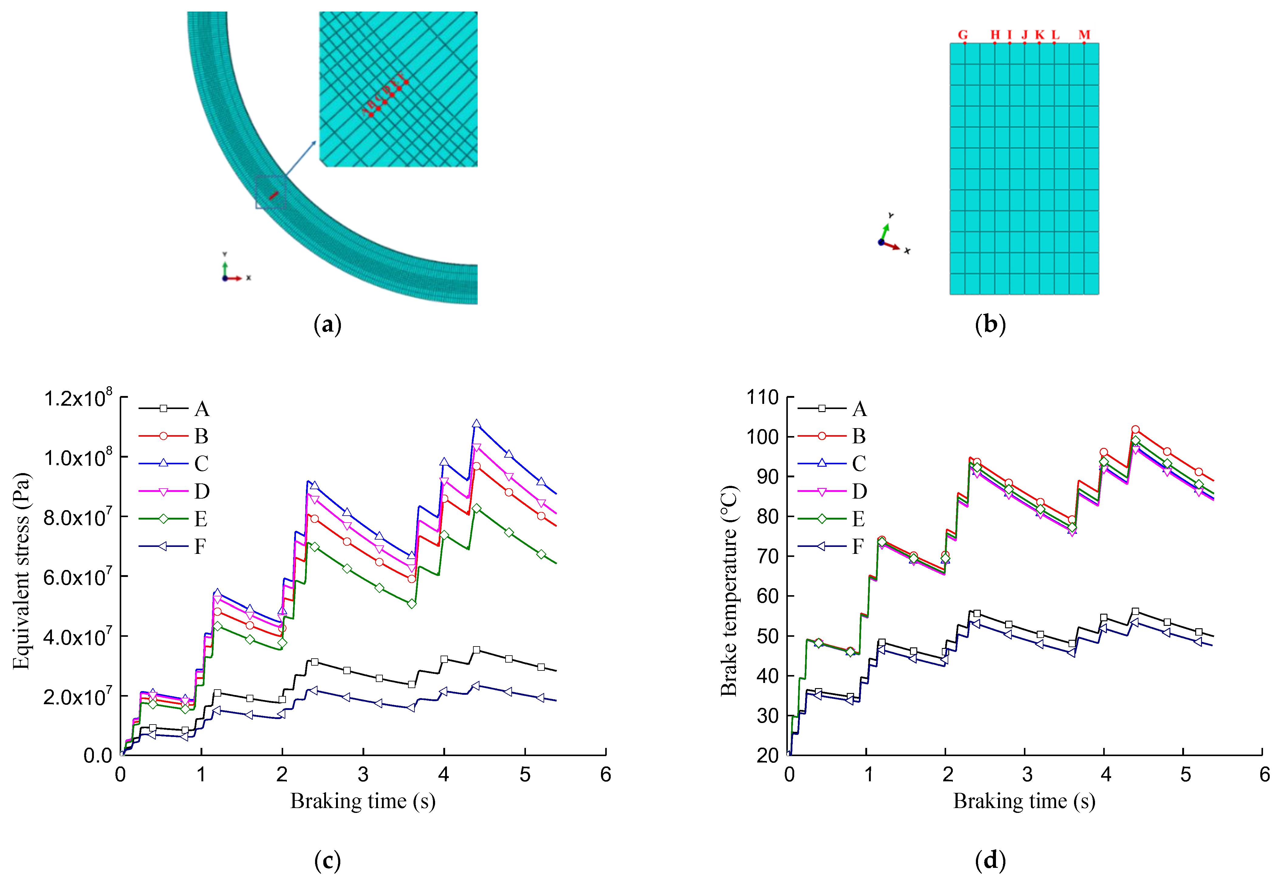
4.2. Effect of Vibration on Thermal Stress Fields of Braking Interfaces

Figure 10a shows that as compared to ignoring vibration, the contact interfaces between the brake disc and the brake shoe exhibit higher equivalent stress and temperature when considering vibration. The maximum equivalent stress and maximum temperature at the contact interfaces increase by 19.1% and 11.3% respectively, which indicates that the vibration effect intensifies the thermal stress fields at the contact interfaces during emergency braking.
Figure 10b shows that the simulated evolution curve of a stepped maximum temperature variation at the contact interface shows an increase at first and then a decrease, which is attributed to the temperature accumulation during emergency braking of combined multiple brake shoes. As it is difficult to measure the temperature field at the contact interface directly during the tests, the temperature at the location just sliding out of the contact interface of the brake disc was measured. The smooth change of the temperature curve without a stepped fluctuation can be attributed to the fact that only one pair of brake shoes were in contact with the brake disc during the emergency braking test and thus there was no temperature accumulation. The experimental temperature change presented an overall increase at first and then a decrease, which we attribute to the larger friction heat generation at first, then the equilibrium state between the heat generation and heat dissipation due to heat transfer and conduction, and a final decrease in the rotational speed, inducing less heat generation [1,3,13]. It was clearly found that the experimental value of the temperature field at the contact interface was smaller as compared to the simulated value during emergency braking due to the lack of temperature accumulation and the measurement of temperature out of the contact interface of the brake shoe. However, the overall change trends of the simulated and experimental temperature change curves during emergency braking were similar, with an increase at first and then a decrease, which validates the finite element model.

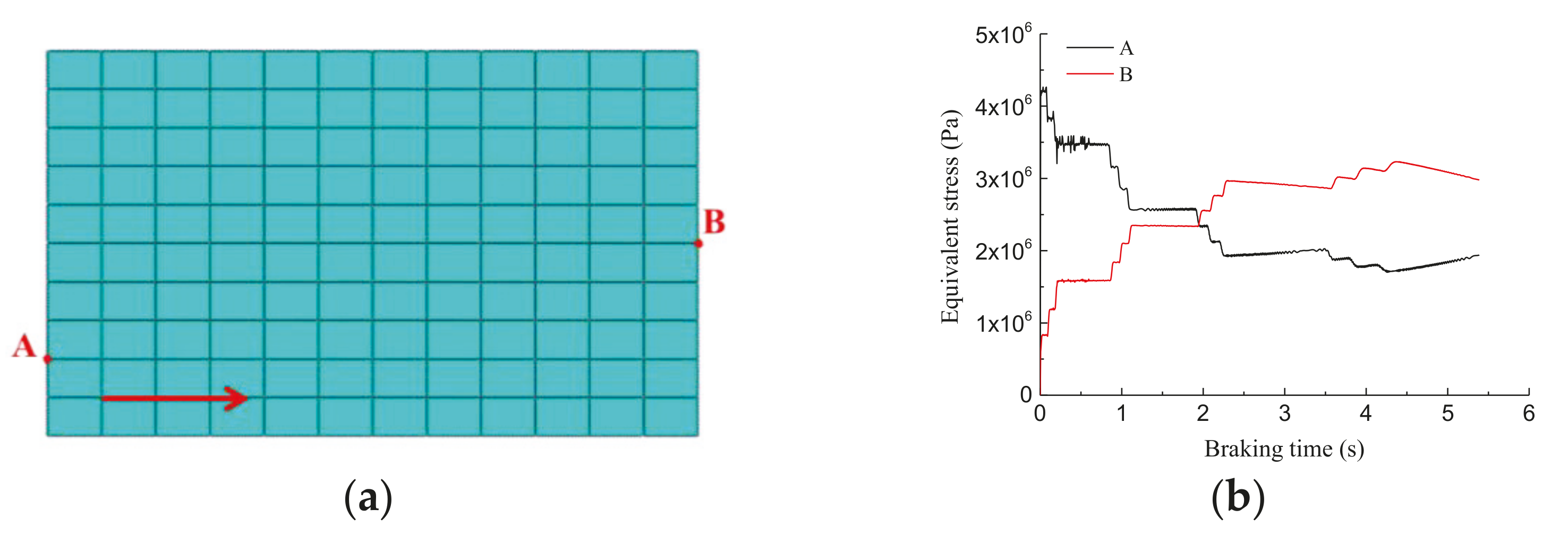
4.3. Evolutions of Thermal Stresses of Braking Interfaces under the Effect of Vibration

Figure 11a,b show that at the typical braking time of 4.380 s during emergency braking, the maximum equivalent stress and temperature at the contact interfaces between the brake disc and the brake shoe were 115 MPa and 102.1 °C, respectively, and were both located at the average friction radius of the brake disc. Meanwhile, the equivalent stress at the average friction radius of the brake disc was higher as compared to that at both sides of the brake disc. Along the anti-clockwise rotation direction of the brake disc, the temperature and equivalent stress at each contact interface of the brake disc both increased gradually, and reached maximum values at the contact interfaces of brake shoes 3 and 6, which can be attributed to the poor thermal convection effect and the superposition effect of frictional thermal stress between the brake disc and the air. However, due to the long distances between brake shoes 3 and 4 and between brake shoes 6 and 1, the long-term heat exchange between the brake disc and the air causes decreases in the equivalent stress and temperature along the rotation direction of the brake disc [3,13]. Figure 11c shows increases in the equivalent stress level from brake shoe 1 to brake shoe 3 and from brake shoe 4 to brake shoe 6, respectively, which indicates the accumulation effect of the equivalent stress of the frictional surface of the brake shoe along the rotation direction of the brake disc. The maximum equivalent stress of each brake shoe was located at the sliding-out side of the brake disc; the brake shoe exhibited a higher equivalent stress level in the middle as compared to the periphery. Figure 11d shows that the contact surface of each brake shoe presents a near-rectangular high temperature distribution zone at one side and exhibited the highest temperature at the sliding-out side of the brake disc due to the cumulative effect of friction heat. In order to reveal the stress distribution difference of the brake shoe at the sliding-in and sliding-out sides of brake disc, we chose two nodes on the contact interface of the brake shoe (Figure 12) and obtained evolution curves of the equivalent stress of both nodes during emergency braking (Figure 12b). Figure 12 shows the larger equivalent stress of the brake shoe at the sliding-out side of the brake disc at the initial stage of emergency braking. Meanwhile, the equivalent stress of the brake shoe decreased with increasing emergency braking time; the equivalent stress level at the sliding-in side of the brake disc was larger as compared to the sliding-out side at the emergency braking time of 2.95 s.
In order to quantitatively reveal the evolution characteristics of the thermal stresses of the brake disc and the brake shoe during emergency braking, and based on the thermal stress accumulation effect along the rotation direction of the brake disc, we chose radial reference nodes of the brake disc and brake shoe 6, as shown in Figure 13a,b. The reference node for the brake disc during emergency braking consisted of the node corresponding to the maximum equivalent stress. Figure 13c shows that equivalent stresses of points C and D near the average friction radius of the contact surface of the brake disc exhibited larger values, and the equivalent stress decreased gradually along the radial direction, which coincided with distribution laws of equivalent stress at the contact surface of the brake disc, outlined in Section 3.3, i.e., the high equivalent stress in the middle and the decreasing trend towards both sides. Figure 13d shows that the temperatures of reference points B, C, D and E near the average friction radius of the brake disc were larger than the temperatures of reference points A and F at the contact edge; the temperatures of reference points B and E were larger as compared to the temperatures of reference points C and D. Therefore, the temperature of the brake disc presented a slight increase and then a decrease along the radial direction from the average friction radius towards both sides of the brake disc. Figure 13c,d show the similar change laws of equivalent stress and temperature of the brake disc. As the reference node of the contact surface of the brake disc passed through three pairs of brake shoes on one side of brake disc, the equivalent stress and temperature both exhibited three rapid increases and two slight decreases. When the reference point of the contact surface of the brake disc passed from one side to the other side of the brake shoe, the equivalent stress and temperature both decreased continuously, which is attributed to the heat convection between the brake disc and the air. It can be clearly seen in Figure 13e that the evolution curves of the equivalent stresses of various reference nodes of the brake shoe indicate that the contact surface of the brake shoe presented high equivalent stresses in the middle locations (reference points H–L) and low equivalent stresses at the edge locations (reference points G and M). The equivalent stress reached the largest values at points I and J, and decreased in the order of reference points H, K and L. The overall change trends of the equivalent stresses of the brake shoe and the brake disc were similar, whereas the vibration effect caused the continuous fluctuation of the equivalent stress of the brake shoe during emergency braking. It can be obviously observed in Figure 13f that the reference point H of the brake shoe exhibited the highest temperature, and the contact surface of the brake shoe presented the higher temperature in the middle location as compared to the edge locations. Figure 13e,f show that the maximum equivalent stresses and temperature of various nodes were not located at the end of emergency braking due to the cumulative effect of frictional heat during emergency braking. However, the small relative sliding speed between the brake disc and the brake shoe at the late stage of emergency braking caused less friction heat generation at the contact surface as compared to the heat convection among the brake disc, brake shoe and the air, which caused both decreases in the equivalent stress and temperature of the brake shoe at the late stage of emergency braking. Figure 13g shows that the equivalent stress of the brake shoe was obviously smaller as compared to that of the brake disc, and the maximum temperature of the contact surface of the brake disc was slightly larger than that of the brake shoe.

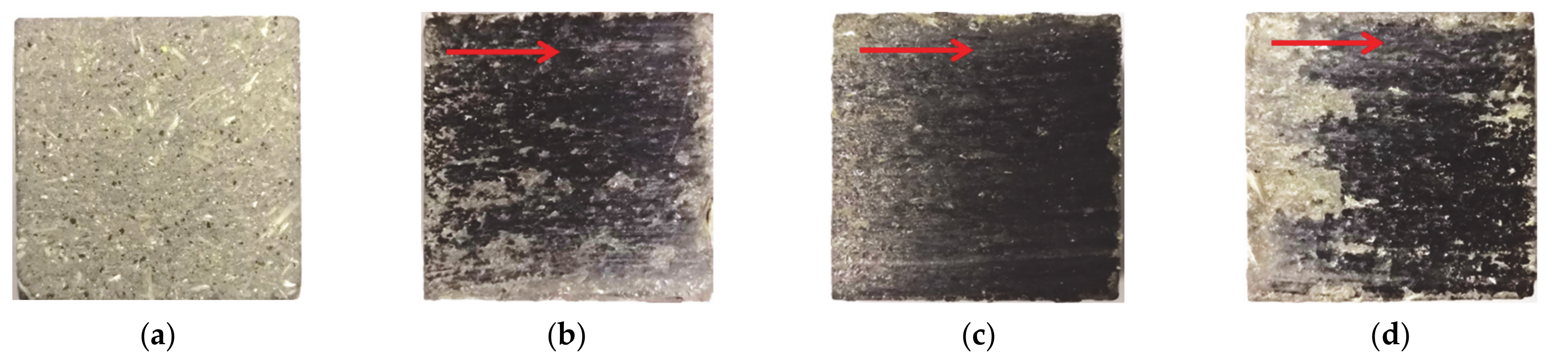
5. Friction Deterioration Behaviors of the Brake Shoe during Emergency Braking

During emergency braking, the brake shoe presents friction deterioration due to the coupled effects of vibration, stress and frictional heat. As the motor is out of control and continues to provide traction torque, continuous friction deterioration occurs between the brake disc and the brake shoe. Therefore, the self-made tribo-brake test rig was employed to conduct emergency braking tests between the brake disc and the brake shoe. Descriptions of the materials of the brake disc and the brake shoe can be found in Section 1. The initial braking speed at the average friction radius of the brake disc was 20 m/s, and the specific braking pressure between the brake disc and the brake shoe was 2 Mpa. In order to reveal the effects of emergency braking cycles and continuous emergency braking time (simulating the loss of control of the motor) on the friction deterioration behaviors of the brake shoe during emergency braking, we chose emergency braking cycles of 5, 10 and 20, and continuous emergency braking times of 30 s, 60 s and 120 s.

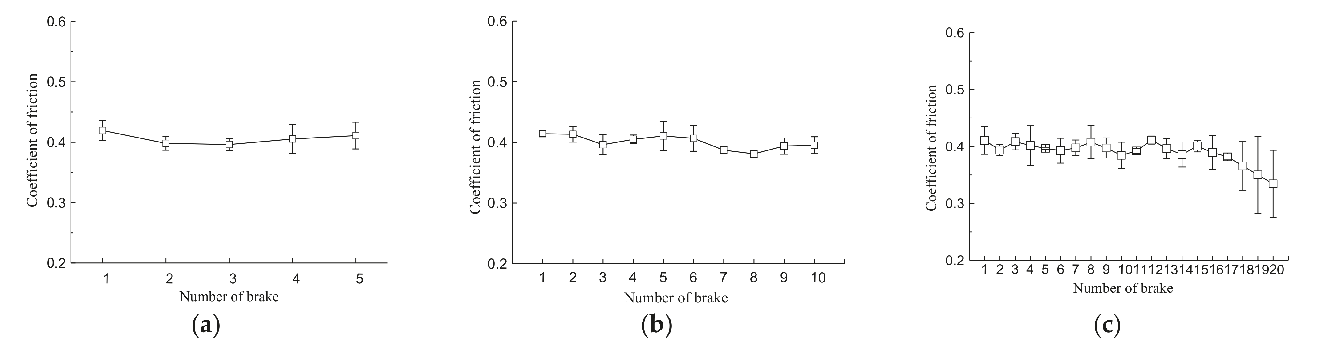
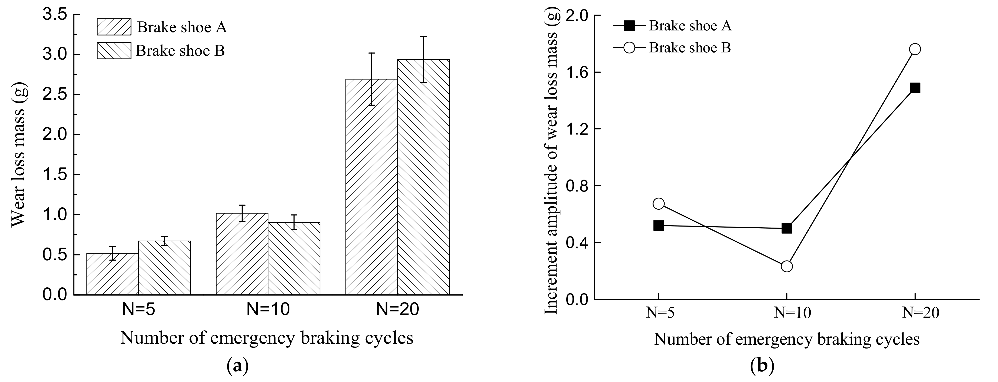
5.1. Effects of Emergency Braking Cycles

It can be clearly seen in Figure 14 that the coefficient of friction between the brake disc and the brake shoe fluctuated around 0.4 in different emergency braking cycles. Figure 15 shows the black friction film at the brake shoe surface after emergency braking. With five emergency braking cycles (Figure 15b), the brake shoe surface exhibited a dense black film in the middle and sparse black film at the edge. As the emergency braking cycles increased to 10 (Figure 15c), the brake shoe surface presented a dense black film and a relatively rough surface at the sliding-in side of the brake disc. Figure 15d shows the rough ploughing and severe material falling off. Therefore, the surface damage of the brake shoe accelerated with increasing emergency braking cycles, which coincides with the finite element results presented in Section 3. Figure 16a shows material accumulation, slight ploughing, as well as many pits and microcracks on the brake shoe surface. It can be clearly seen in Figure 16b that the brake shoe surface presented a large number of microcracks, ploughing, lots of small pits and material asperities. It can be observed in Figure 16c that the brake shoe surface presented a large area of pits and material asperities, lots of microcracks, material peeling off and a great amount of wear debris. Therefore, the surface damage to the brake shoe was aggravated by increasing the number of emergency braking cycles.
Figure 17 shows that increases in the number of emergency braking cycles caused gradual increases in the wear mass losses of the brake shoes at both sides of the brake disc. However, as emergency braking cycles increased from 10 to 20, the increase rate of the wear mass loss of the brake shoe increased sharply. This is because at 5, 10 and 20 emergency braking cycles, the brake disc and brake shoe were located at initial wear, stabilized wear and severe wear states, respectively, which coincides with the wear mechanisms of the brake shoe as shown in Figure 16.

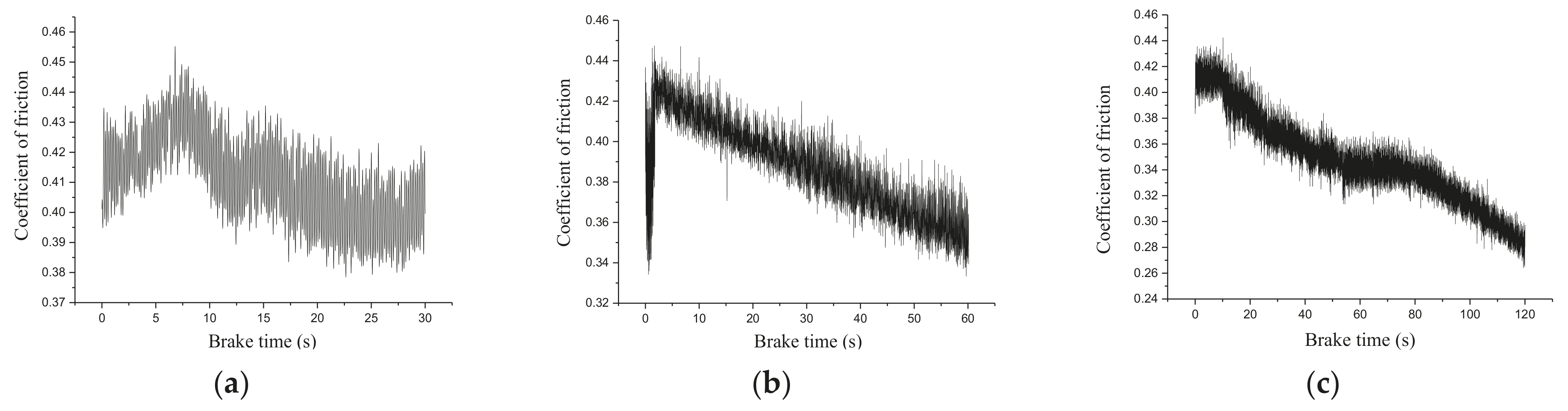
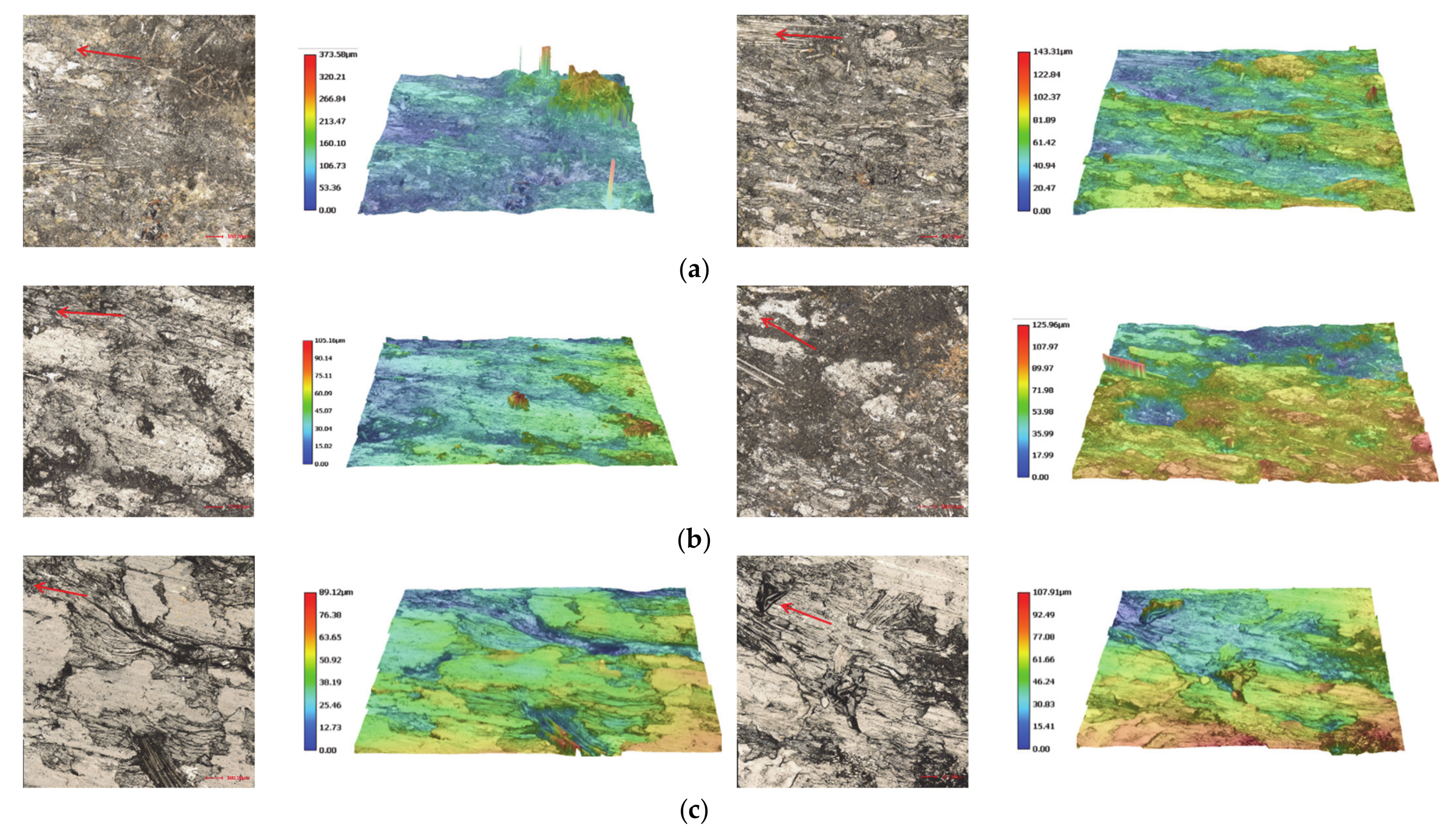
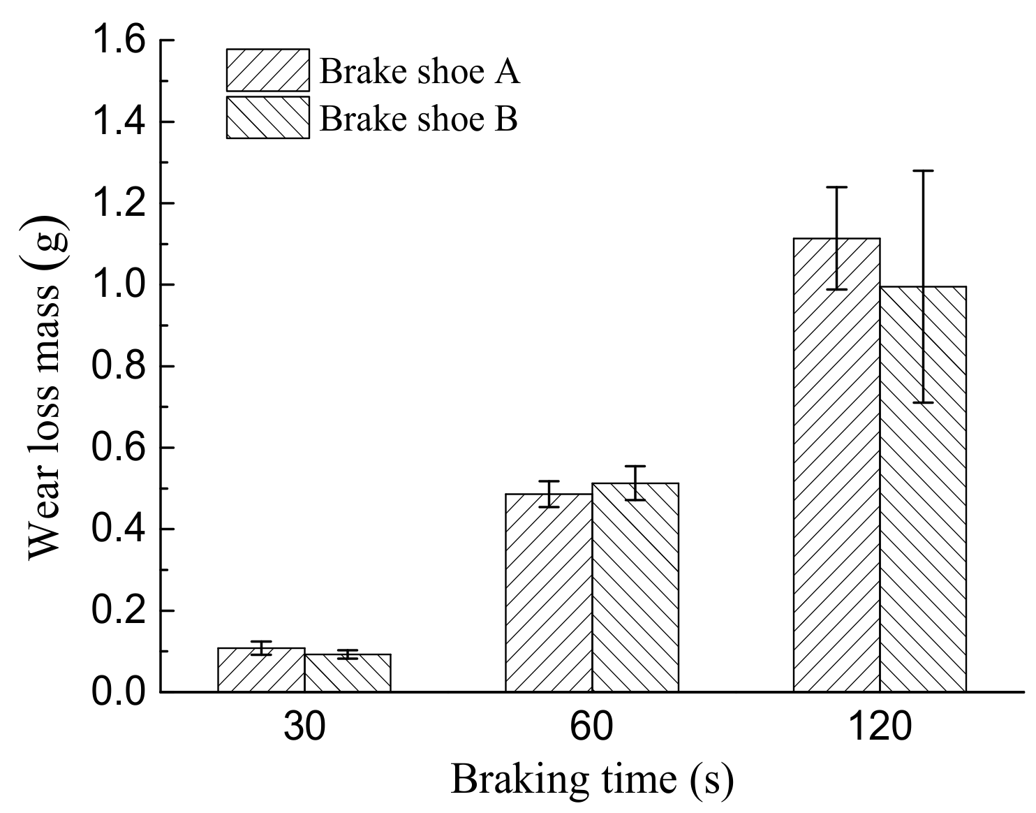
5.2. Effect of Continuous Emergency Braking Time

Figure 18 shows that the coefficient of friction between the brake disc and the brake shoe increased at first and then decreased in cases of distinct emergency braking time. In the case of an emergency braking time of 120 s, the coefficient of friction stabilized at approximately 0.34 in the emergency time range of 50–80 s, then gradually decreased and finally decreased to 0.23 at the end of the test, which indicates a significant decrease in the emergency braking ability. During continuous emergency braking, the coefficient of friction presented a large fluctuation amplitude due to the coupled roles of the motor driving torque and the braking friction force’s strengthening of the vibration effect of the brake pair.
Figure 19 shows different degrees of surface damage of the brake shoe after emergency braking with different continuous times. After the continuous braking time of 30 s (Figure 19a), the brake shoe surface presented many small pits and ploughing. Figure 19b shows that the brake shoe surface exhibited lots of small pits, rough ploughing and black friction film. As the continuous braking time reached 120 s, the brake shoe surface showed a large area of black friction film, fracturing of materials at the edge, aggravated ploughing and a large number of cracks. The black friction film may be burning marks caused by the long continuous braking time, the continuous increase in the temperature rise between the brake disc and the brake shoe and the poor heat dissipation. Figure 20a shows that the brake shoe surface exhibited material asperities, pits, many microcracks, a large number of composite fibers peeling off and the ploughing phenomenon. It can be clearly seen in Figure 20b that the brake surface exhibited lots of material adhesion and black debris particles, a great number of asperities and pits, rough ploughing and many microcracks. It can be obviously observed in Figure 20c that the brake shoe surface presented aggravated ploughing, large areas of asperities and pits, severe damage to the microstructure, a large number of large-sized cracks, severe material peeling off and black molten aggregates. Figure 21 shows that an increase in the continuous braking time causes an increase in the wear mass of the brake shoe.
In conclusion, as compared to the cyclic emergency braking behavior of the brake shoe, the continuous tribo-brake after emergency braking—simulating the loss of control of the motor—causes a more obvious degradation of the tribological performance of the brake shoe. After emergency braking, an increase in the continuous braking time accelerates the brake shoe surface; the brake disc and brake shoe exhibit material adhesion and migration phenomena. As the continuous braking time increases, the high thermal stress state and poor heat dissipation cause the generation of black molten aggregates on the brake shoe surface, which seriously reduces the tribo-braking performance between the brake disc and the brake shoe (Figure 18) and which would not provide a safe and reliable friction force during emergency braking.

6. Conclusions

The vibration was obvious along the direction of braking pressure between the brake disc and the brake shoe, as compared to unobvious vibrations in other directions, during emergency braking in the case of all the brake shoes evaluated. Furthermore, the vibration intensity was larger at the low-frequency zone as compared to the high-frequency zone, which was observed for all brake shoes.
Coupled roles of vibration, frictional heat and stress were observed between the brake disc and the brake shoe during emergency braking. The effect of vibration caused fluctuating changes and increases in the equivalent Von Mises stress and temperature at the contact interfaces between the brake disc and the brake shoe. Along the rotation direction of the brake disc, the equivalent stress and temperature at the reference point of the brake disc surface both presented three overall rapid increases and two slight decreases during emergency braking between the brake disc and the brake shoe. Different emergency braking stages caused distinct equivalent stress and temperature distributions of the brake shoe at the sliding-in and sliding-out sides of the brake disc.
Increases in the number of emergency braking cycles and the continuous emergency braking time both accelerated the surface damage to the brake shoe and induced increases in the wear losses of the brake shoe. As compared to cyclic emergency braking, continuous emergency braking exhibited more obvious tribological degradation of the brake shoe, attributed to the enhanced effect of vibration through the coupled roles of driving torque and braking friction.

Author Contributions

Conceptualization, D.W.; methodology, D.W.; validation, R.W. and B.W.; formal analysis, D.W. and R.W.; data curation, D.W., R.W. and B.W.; writing—original draft preparation, R.W.; writing—review and editing, D.W., B.W. and M.A.W.; supervision, D.W.; funding acquisition, D.W. All authors have read and agreed to the published version of the manuscript.

Funding

The research reported here was supported by the Fundamental Research Funds for the Central Universities (Grant no. 2018XKQYMS14). The authors also wish to thank TAPP and PAPD.

Institutional Review Board Statement

Not applicable.

Informed Consent Statement

Not applicable.

Conflicts of Interest

The authors declare no conflict of interest.

References

  1. Wang, D.G.; Yin, J.K.; Zhu, Z.C.; Zhang, D.K.; Liu, D.H.; Liu, H.W.; Sun, F.Q. Preparation of High Friction Brake Shoe Material and Its Tribological Behaviors during Emergency Braking in Ultra-Deep Coal Mine Hoist. Wear 2020, 458, 203391. [Google Scholar] [CrossRef]
  2. Wang, D.G.; Li, X.W.; Wang, X.R.; Shi, G.; Mao, X.; Wang, D. Effects of Hoisting Parameters on Dynamic Contact Characteristics between the Rope and Friction Lining in a Deep Coal Mine. Tribol. Int. 2016, 96, 31–42. [Google Scholar] [CrossRef]
  3. Wang, D.G.; Wang, R.X.; Zhang, J. Dynamic Brake Characteristics of Disc Brake during Emergency Braking of the Kilometer Deep Coal Mine Hoist. Adv. Mech. Eng. 2020, 12, 1–23. [Google Scholar] [CrossRef]
  4. Wang, D.G.; Zhang, J.; Ge, S.R.; Zhang, D.; Shi, G. Mechanical Behavior of Hoisting Rope in 2 Km Ultra Deep Coal Mine. Eng. Fail. Anal. 2019, 106, 104185. [Google Scholar] [CrossRef]
  5. Yun, C.K.; Min, H.C.; Kim, S.J.; Jang, H. The Effect of Phenolic Resin, Potassium Titanate, and Cnsl on the Tribological Properties of Brake Friction Materials. Wear 2008, 264, 204–210. [Google Scholar] [CrossRef]
  6. Satapathy, B.K.; Bijwe, J. Performance of Friction Materials Based on Variation in Nature of Organic Fibres: Part I. Fade and Recovery Behaviour. Wear 2004, 257, 585–589. [Google Scholar] [CrossRef]
  7. Wang, Z.J.; Wang, C.L.; Li, D. Study on the Influence Mechanism of the Temperature Rise and Frictional Coefficient of Brake Shoe on Braking of Mine Hoist. J. China Coal Soc. 2005, 30, 149–152. [Google Scholar]
  8. Bao, J.S.; Zhu, Z.C.; Tong, M.; Yin, Y.; Peng, Y. Influence of Braking Pressure on Tribological Performance of Non-Asbestos Brake Shoe for Mine Hoister During Emergency Braking. Ind. Lubr. Tribol. 2012, 64, 230–236. [Google Scholar] [CrossRef]
  9. Olesiak, Z.; Pyryev, Y.; Yevtushenko, A. Determination of Temperature and Wear during Braking. Wear 1997, 210, 120–126. [Google Scholar] [CrossRef]
  10. Zhu, Z.C.; Peng, Y.X.; Shi, Z.Y.; Cheng, G.-A. Three-Dimensional Transient Temperature Field of Brake Shoe during Hoist’s Emergency Braking. App. Therm. Eng. 2009, 29, 932–937. [Google Scholar] [CrossRef]
  11. Zhu, Z.C.; Bao, J.S.; Yin, Y.; Chen, G.A. Frictional Catastrophe Behaviors and Mechanisms of Brake Shoe for Mine Hoisters during Repetitious Emergency Brakings. Ind. Lubr. Tribol. 2013, 65, 245–250. [Google Scholar] [CrossRef]
  12. Pyryev, Y.; Yevtushenko, A. Influence of the Brakes Friction Elements Thickness on the Contact Temperature and Wear. Heat Mass Transf. 2000, 36, 319–323. [Google Scholar] [CrossRef]
  13. Wang, D.G.; Wang, R.X.; Heng, T.; Xie, G.; Zhang, D. Tribo-Brake Characteristics between Brake Disc and Brake Shoe during Emergency Braking of Deep Coal Mine Hoist with High Speed and Heavy Load. Energies 2020, 13, 5094. [Google Scholar] [CrossRef]
  14. Zhou, H.B.; Yao, P.P.; Xiao, Y.L.; Fan, K.; Zhang, Z.; Gong, T.; Zhao, L.; Deng, M.; Liu, C.; Ling, P. Friction and Wear Maps of Copper Metal Matrix Composites with Different Iron Volume Content. Tribol. Int. 2019, 132, 199–210. [Google Scholar] [CrossRef]
  15. Xing, J.H.; Huang, H.; Zhang, J.Y.; Yang, Q.S. Mechanical Properties of Disc Springs. J. Vib. Shock 2015, 22, 167–172. [Google Scholar] [CrossRef]
  16. Piao, G.; Zhang, B.L.; Gao, J.H.; Guo, B. An Experimental Research Method of Disc Spring’s Mechanical Properties. Mech. Eng. Autom. 2014, 3, 114–116. [Google Scholar] [CrossRef]
  17. Jin, M.J.; Yan, J.M.; Lu, Z.Q. Braking Moment and Oil Pressure of a Mine Hoist. J. Taiyuan Heavy Mach. Inst. 2001, 22, 214–216. [Google Scholar] [CrossRef]
  18. Pan, Y.; Xia, R. Dynamic Tension in Wire Ropes during Emergency Braking on Shaft Hoists. J. China Univ. Min. Technol. 1982, 3, 52–70. [Google Scholar]
  19. Liu, F.F. Study on Thermal-Stress Coupling Behavior of Brake Shoe during Emergency Braking of Hoist. Xuzhou, China. J. China Univ. Min. Technol 2011. [Google Scholar]
  20. Zhao, Y.J. Simulation and Analysis of Disc Brake Coupled Thermal-Stress Transient Temperature. J. Wuhan Huazhong Univ. Sci. Technol. 2013. [Google Scholar] [CrossRef]
Figure 1. Specific heat capacity and thermal expansion rate of the brake shoe. (a) Specific heat capacity (b) Thermal expansion rate.
Applsci 11 06441 g001
Figure 2. Tribological characteristics of brake shoe during emergency braking; (a) coefficient of friction and temperature rise of the brake disc surface; (b) average coefficients of friction during the emergency braking at distinct speeds; (c) wear rate of brake shoe (the solid line indicating the average value of three tests).
Applsci 11 06441 g002
Figure 3. Dynamic model of the disc brake of a deep coal mine hoisting system.
Applsci 11 06441 g003
Figure 4. Evolutions of dynamic torque exerted on the drum during emergency braking. (a) Dynamic torque exerted on the drum in cases of different hoisting stages; (b) fitting curve of dynamic torque in the acceleration stage of hoisting; (c) fitting curve of dynamic torque in the constant speed stage of hoisting.
Applsci 11 06441 g004
Figure 5. Evolutions of acceleration and brake force of brake shoe and brake shoe numbering. (a) Theoretical acceleration in the X direction; (b) theoretical acceleration in the Y direction; (c) theoretical acceleration in the Z direction; (d) experimental brake force in the Z direction; (e) schematic diagram of brake shoe numbering.
Applsci 11 06441 g005
Figure 6. Evolution curves of accelerations in the Z direction of brake shoes 1-12. (a) Brake shoes 1-1 to 6-1 (b) brake shoes 1-2 to 6-2 (c) brake shoes 7-1 to 7-1 (d) brake shoes 7-2 to 12-2.
Applsci 11 06441 g006
Figure 7. Vibration frequencies of brake shoes 1-3. (a) Brake shoe 1-1 (b) brake shoe 1-2 (c) brake shoe 2-1 (d) brake shoe 3-1.
Applsci 11 06441 g007
Figure 8. Emergency braking model of a brake shoe under vibration conditions.
Applsci 11 06441 g008
Figure 9. The specific braking pressure and braking force application of the brake shoe. (a) Specific braking pressure of the brake shoe; (b) schematic diagram of braking force application of the brake shoe.
Applsci 11 06441 g009
Figure 10. Comparisons of equivalent stresses and temperature at the contact surfaces of the brake disc considering and ignoring vibration. (a) Maximum equivalent stresses and temperature at the contact surfaces of the brake disc considering and ignoring vibration. (b) Theoretical and experimental temperature rise at the contact surface of the brake disc.
Applsci 11 06441 g010
Figure 11. Distributions of equivalent stresses and temperature of the brake disc and the brake shoe at the typical moment of 4.38 s during emergency braking (the red arrow represents the sliding direction of the brake disc). (a) Distributions of equivalent Von Mises stresses of the brake disc and the brake shoe. (b) Distributions of temperature fields of the brake disc and the brake shoe. (c) Distributions of equivalent stresses of the contact surfaces of brake shoes 1-6. (d) Distributions of temperature fields of the contact surfaces of brake shoes 1-6. (Note: in the figures, e+02 is equivalent to × 102 for example).
Applsci 11 06441 g011aApplsci 11 06441 g011b
Figure 12. Evolution curves of equivalent stresses at both sides of brake shoe 6. (a) Selection of reference points. (b) Evolution curves of equivalent stresses.
Applsci 11 06441 g012
Figure 13. Equivalent stresses and temperature of the brake disc and the brake shoe during emergency braking. (a) Reference points at the contact surface of the brake disc. (b) Reference points at the contact surface of the brake shoe. (c) Evolutions of equivalent stresses of reference points at the contact surface of the brake disc. (d) Evolutions of temperature of reference points at the contact surface of the brake disc. (e) Evolutions of equivalent stresses of reference points at the contact surface of the brake shoe. (f) Evolutions of temperature of reference points at the contact surface of the brake shoe. (g) Maximum equivalent stresses and temperature of the brake disc and the brake shoe.
Applsci 11 06441 g013aApplsci 11 06441 g013b
Figure 14. Coefficients of friction between the brake disc and the brake shoe with different numbers of emergency braking cycles. (a) 5 cycles (b) 10 cycles (c) 20 cycles.
Applsci 11 06441 g014
Figure 15. Morphologies of brake shoe specimens with different numbers of emergency braking cycles (the red arrow represents the sliding direction of the brake disc). (a) Original surface (b) after 5 cycles (c) after 10 cycles (d) after 20 cycles.
Applsci 11 06441 g015
Figure 16. Microscopic morphologies and three-dimensional profiles of brake shoe specimens at both sides of the brake disc with different numbers of emergency braking cycles (the red arrow represents the sliding direction of brake disc). (a) 5 cycles; (b) 10 cycles; (c) 20 cycles.
Applsci 11 06441 g016
Figure 17. Wear loss masses and their increment amplitudes in brake shoes with different numbers of emergency braking cycles. (a) Wear loss mass (b) increment amplitude of wear loss mass.
Applsci 11 06441 g017
Figure 18. Evolutions of coefficient of friction between the brake disc and the brake shoe in cases of different emergency braking times. (a) 30 s (b) 60 s (c) 120 s.
Applsci 11 06441 g018
Figure 19. Surface morphologies of brake shoe specimens in cases of distinct braking times (the red arrow represents the sliding direction of the brake disc). (a) t = 30 s; (b) t = 60 s; (c) t = 120 s.
Applsci 11 06441 g019
Figure 20. Microscopic morphologies and three-dimensional profiles of brake shoe specimens at both sides of the brake disc in cases of different emergency braking times (the red arrow represents the sliding direction of the brake disc). (a) t = 30 s; (b) t = 60 s; (c) t = 120 s.
Applsci 11 06441 g020
Figure 21. Wear loss masses of brake shoe specimens in cases of different emergency braking cycles.
Applsci 11 06441 g021
Table 1. Thermal expansion coefficient of the brake shoe.
Temperature Range (°C)30–4040–5050–6060–7070–8080–9090–100100–114
Thermal Expansion Coefficient (×10−6/°C)8.3311.851212.2611.049.247.906.54
Table 2. Evolution equations of dynamic torque exerted on the drum and corresponding fitting coefficients during emergency braking in cases of distinct hoisting stages.
Hoisting StageEquation FormFitting Coefficients
Acceleration(5)a0 = −7.438 × 10⁶; a1 = −9.777 × 10⁶; b1 = 2.117 × 10⁷; a2 = 1.205 × 10⁷; b2 = 1.018 × 10⁷; a3 = 9.083 × 10⁶, b3 = −4.612 × 10⁶; a4 = −4.979 × 10⁵, b4 = −5.407 × 10⁶; a5 = −3.411 × 10⁶, b5 = −9.719 × 10⁵; w = 1.353
Constant speed(6)a1 = 7.837 × 10⁶, b1 = 0.6227, c1 = −0.1956; a2 = 3.538 × 10⁶, b2 = 2.766, c2 = −2.755; a3 = 4.36 × 10⁶, b3 = 1.278, c3 = 1.081; a4 = 1.034 × 10⁶, b4 = 3.489, c4 = 4.363; a5 = 3.744 × 10⁵, b5 = 3.853, c5 = 6.447
Deceleration(6)a1 = 9.48 × 10⁶, b1 = 1.279, c1 = −0.5925; a2 = 2.327 × 10⁶, b2 = 6.504, c2 = 3.287; a3 = 9.069 × 10⁶, b3 = 3.015, c3 = 2.71; a4 = 1.157 × 10⁷, b4 = 2.62, c4 = 0.1908; a5 = 3.482 × 10⁵, b5 = 7.563, c5 = 4.704
Publisher’s Note: MDPI stays neutral with regard to jurisdictional claims in published maps and institutional affiliations.

