Article

Two-Beam Free-Electron Lasers and Self-Injected Nonlinear Harmonic Generation

ENEA—Frascati Research Center, Via Enrico Fermi 45, 00044 Rome, Italy
*
Author to whom correspondence should be addressed.
Appl. Sci. 2021, 11(14), 6462; https://doi.org/10.3390/app11146462
Submission received: 31 May 2021 / Revised: 26 June 2021 / Accepted: 5 July 2021 / Published: 13 July 2021

Abstract

:
The possibility of extending the tunability of Free-Electron Lasers towards short wavelengths has been explored through the design of devices conceived to enhance the mechanisms of nonlinear harmonic generation. In this respect, different schemes of operation have been suggested in the past, such as harmonic seeding, bi-harmonic undulators, and two-beam self-seeding devices. In this paper, we discuss how these methods can be merged into a tool, extending the performance of FEL devices.

1. Introduction

Nonlinear harmonic generation (NLHG) is one of the key mechanisms adopted to extend the spectral tunability range of Free-Electron Laser (FEL) [1,2,3,4,5]. Harmonic seeding [6,7] and NLHG have been widely exploited in the past to push the FEL and its application towards shorter wavelengths. Other suggestions, although promising, have been carefully studied, but have not found specific applications so far.
In this article, we discuss the possibility of combining two different proposals, developed in the past, concerning the use of devices exploiting NLHG in high-gain FEL devices [4,8]. We deal with the harmonically coupled two-beam self-injection [9] and bi-harmonic undulators [10,11], conceived to enhance the FEL coherent harmonic content emission and extend the capabilities of the device itself.
(a)
Nonlinear Harmonic Generation
Although the mechanism of nonlinear harmonic generation occurs in a FEL device operating with linearly and helically polarized undulators, here we treat the linear case only and consider undulators with on-axis field vector
B u B 0 0 , sin ( k u z ) , 0 .
The pattern to the higher harmonic emission is an intrigued interplay between all the processes underlying the FEL lasing and involving energy modulation, bunching, coherent emission, higher-order bunching, and saturation [7]. The relevant study is afforded by exploiting a generalization of the FEL pendulum equations, including the evolution of the fields of the individual harmonics, namely [1]
d 2 d τ 2 ζ = n = 0 a n cos ψ n , ψ n = n ζ + ϕ n , a n = a n e i ϕ n , d d τ a n = j n e i n ζ .
where n refers to the order of the harmonic, ( a , j ) are the Colson’s dimensionless amplitude and current respectively, ζ is the dimensionless electron phase, finally the brackets denote averages on the initial phase distribution. The modulus of a is linked to the field intensity (power density ) I by the identities
a 2 = 8 π 2 I I s , I s = c 8 π m e c 2 e 2 γ N 4 λ u K 2 f b 2 .
The quantity I s denotes the FEL saturation intensity, a key quantity either in FEL and conventional lasers. It controls the onset of saturation, which starts playing a role when the FEL intensity is close to I s [12].
The physical content of the previous set of equations can be summarized as follows. The fundamental harmonic (n = 1) drives the bunching, which allows the growth of the different harmonics if the corresponding dimensionless currents j n are nonvanishing. In the case of FEL devices operating with linear undulators, this is automatically ensured by the on-axis coupling to odd harmonics.
An example of nonlinear harmonic generation intensity growth is given in Figure 1, drawn using the analytical formulae summarized in Equation (4). The relevant agreement with numerical computation has been benchmarked with the Prometeo code [13], as discussed below.
The process consists of two distinct parts. In the first, the fundamental (n = 1) and higher-order harmonics (3,5) grows independently, till the bunching at higher harmonics, induced by the fundamental, triggers the nonlinear harmonic generation mechanisms.
The analytical procedure developed in the past [14] yields a fairly straightforward description of the different evolution steps. The model equations are reported below, and we have denoted with Λ n z and Π n z the terms accounting for the small-signal and nonlinear harmonic generation parts respectively
P 1 = P 1 z = P 0 A z 1 + P 0 P F , 1 A z 1 , A z = 1 9 3 + 2 cosh z L g , 1 + 4 cos 3 2 z L g , 1 cosh z 2 L g , 1 , P n z = Λ n z + Π n z , n = 3 , 5 Λ n z = P 0 , n A n z . For the case with n > 1 the gain length should be replaced by L g , n * = λ u 4 π 3 ρ n * = n 1 1 3 3 L g , n , ρ n * = n 1 1 3 3 ρ n ,   P 0 , n   input seed power , ρ n n th harmonic Pierce parameter , ρ n = ( f b , n f b , 1 ) 2 3 ρ 1 , f b , n = J n 1 2 ( n ξ ) J n + 1 2 ( n ξ ) ,   ξ = 1 4 K 2 1 + K 2 2 , ρ 1 8.63 × 10 3 γ [ J   ( λ u K   f b , 1 ) 2 ] 1 3 .
The formula for the Pierce parameter of the harmonic ( ρ 1 ) is expressed in a practical form, where J is given in A / m 2 and λ u in m. The NLHG contributions are specified by the formulae
Π n z = Π 0 , n exp n z L g , 1 1 + Π 0 , n Π F , n exp n z L g , 1 1 , Π 0 , n = c n P 0 9 ρ 1 P E n Π F , n , c 3 = 8 , c 5 = 116 , Π F , n = n ρ n n ρ 1 3 P F , 1 = 1 n f b , n n f b , 1 2 P F , 1 ,
where the saturated power P F , 1 reads
P F , 1 = 2 ρ 1 P E
and P E is the e-beam power.
We note therefore that
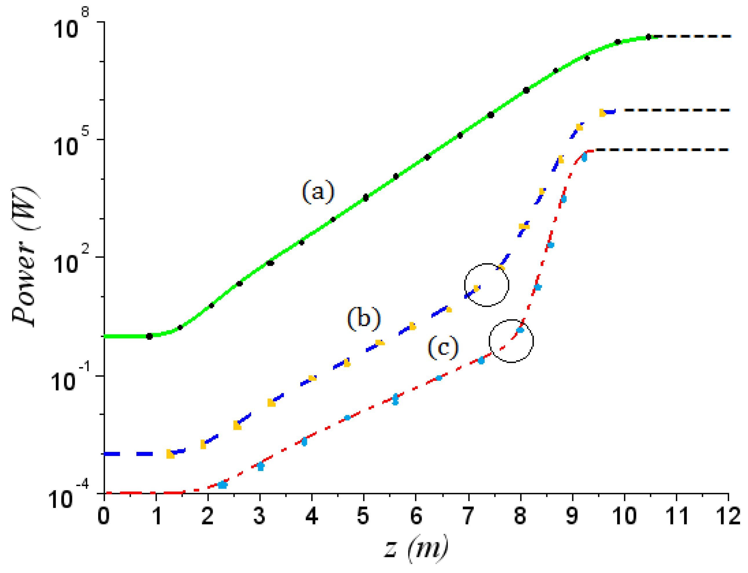
  • The first harmonic power grows initially by exhibiting the lethargic phase followed by the exponential behavior, characterized by the gain length L g , 1 .
  • The same occurs for the higher-order harmonics (with gain length L g , n * ), till the bunching effects trigger the mechanism of nonlinear harmonic generation.
  • This last phase is characterized by a sudden change in the growth rate followed by a kind of saturation. The characteristic gain length is a fraction of that of the fundamental (namely L n ( N H ) = L g , 1 n ).
The inflexion point (before the change in the intensity growth derivative) occurs at z = z , where the Λ n z and Π n z contributions balance. The dots refer to a numerical benchmark with the code Prometeo, for a set of specific parameters. After the saturation the figure exhibits a flat top, without displaying the characteristic power oscillations. This is an artefact of the analytical approximations. It should be noted that, although not significant for the present discussion, these oscillations can be included in the analytical scheme as shown in refs. [15,16].
(b)
Bi-Harmonic undulator
The use of bi-harmonic undulators [10,11] has been suggested in the past as a device allowing the enhancement of the nonlinear harmonic generation in high-gain FEL devices.
In the case of an undulator exhibiting a field with linear orthogonal polarization, specified by the vector
B u 3 B 0 sin ( 3 k u z ) , B 0 sin ( k u z ) , 0 ,
The corresponding FEL pendulum equation can be written by extending those reported in (2) and reads
2 ζ x , 1 τ 2 = | a x , 1 | cos ( ζ x , 1 + φ x , 1 ) , a x , 3 τ = j x , 3 e i ζ x , 3 , a x , 1 τ = j x , 1 e i ζ x , 1 , a y τ = j y e i ζ y ; ζ x , 3 = ζ y = 3 ζ x , 1 .
The relevant physical meaning is not dissimilar from that discussed as a comment to Equation (2). In this case, we have considered 1st and 3rd harmonics only, with the significant difference that two “third” harmonics, with orthogonal polarization, are driven by the fundamental. The third harmonics bears both vertical and linear polarization components and the relevant dimensionless amplitude are defined as
| a σ | 2 = 0.8 π 4 I σ I s , σ ,
where σ = x , y and I s is the associated saturation intensity
I s , σ M W cm 2 = 6.9 × 10 2 γ N σ 4 [ λ u , σ [ cm ] K f b , σ ( ξ ) ] 2 .
Please note that N x = 3 N y , λ u , x = λ u , y / 3 .
The corresponding Bessel factors are specified below (the wavelength of the first harmonic is λ 1 = ( λ u / 2 γ 2 ) ( 1 + K 2 ) . Further comments are provided in Section 3)
f b , 1 x = 3 J 0 ξ , ξ 3 3 J 1 ξ , ξ 3 , f b , 3 x = 3 J 1 3 ξ , ξ + 3 J 2 3 ξ , ξ , f b , 3 y = 3 J 0 3 ξ , ξ 3 J 2 3 ξ , ξ , ξ = 1 4 K 2 1 + K 2 ,
and m J n x , y are generalized Bessel functions defined through the generating function
n = + t n m J n x , y = e x 2 t 1 t + y 2 t m 1 t m ,
and the series expansions (for further comments see ref. [17])
m J n x , y = l = + J l ( x ) J n m l ( y ) .
In Figure 2 an example is given of bi-harmonic power growth. The 1-D simulation displays the already anticipated behavior: along with the fundamental “two” third harmonics, with radial and vertical components, are generated through the nonlinear mechanism.
The physical content of the figure is not different from what we have already discussed when we commented Figure 1 and is worded as reported below. The first harmonic grows and induces, via NLHG, two third harmonics with distinct orthogonal polarizations. The signature for the nonlinear growth is specified by the abrupt change of the growth rate. The two phases of the growth are characterized by the respective gain lengths, namely
L g , 3 x * = 1 3 1 / 3 λ u 4 π 3 ρ 3 x , L g , y * = λ u 4 π 3 3 1 / 3 ρ y ,
and
L g ( N H ) = L g , 1 x 3 ,
where
ρ 1 x 8.63 × 10 3 γ J ( λ u K f b , 1 x ) 2 1 / 3 , ρ 3 x = ρ 1 x f b , 3 x f b , 1 x 3 2 , ρ y = ρ 1 x 1 3 f b , 3 y f b , 1 x 3 2 .
The y-polarized component is significantly larger than its x-counterpart and grows almost at the level of the first.
This is an interesting result since, for the single harmonic undulator, the third exhibits a power of two orders of magnitude below that of the fundamental.
The proposal, the design and construction of this type of undulator traces back to more than three decades ago [18,19]. Although exploited in Storage Ring (SR) sources, they did not find any specific application in the development of FEL, although they have been extensively discussed in the literature [20].
It is certainly true that such a structure is not easy to design, to measure and to handle. Possible alternatives are ensured by segmented undulators, consisting of two undulator sections with emission frequency of the second a sub-multiple of the first [21,22,23]. Such a solution, more manageable from the technical point of view, preserves some of the features of the whole device and will be commented on in the concluding section.
A further possibility, suggested by McNeil, Robb and Poole [24] is that of the harmonically coupled 2-beam FEL (HCB). In their proposal, it is foreseen the use of two beams operating at different energies, passing through a linearly polarized undulator, to run an FEL operating at different harmonics. The relativistic factor of the higher energy beam is chosen in such a way that γ 2 = n γ 1 .
In loose terms, the mechanism of growth of the FEL signal can be described as reported below. The first beam induces the bunching conditions to trigger the third harmonics, if n = 3 , which eventually seeds the first harmonic emitted by the higher energy beam.
In the forthcoming section we model the dynamics of the harmonically coupled beams FEL, using the already quoted semi-analytical procedure [14].

2. Harmonically Coupled Two Beams and High-Gain FELs

As already underlined the HBC scheme foresees two beams with energies γ 1 and γ 2 = n γ 1 , both injected in a linearly polarized undulator. Instabilities of two-stream nature, spoiling the FEL dynamics do not play any role because of the (large) beam energies.
The condition on the energies of beams (1) and (2), ensures that the first harmonic, radiated by the beam (2), coincides with one of the higher-order harmonics of the first (1).
As already established, the two beams radiate independently and give rise to two distinct FEL process, until the n-th harmonic, of the beam with lower energy, seeds that emitted by the beam with larger energy.
The Pierce parameter associated with the two beams are
ρ ( 1 ) J ( 1 ) 3 U ( λ u , K ) , ρ ( 2 ) 1 n J ( 2 ) 3 U ( λ u , K ) , U ( λ u , K ) = 8.36 × 10 3 γ 1 λ u K f b ( K ) 2 3 ,
The Pierce parameters are therefore linked by
ρ ( 2 ) ρ ( 1 ) = 1 n J ( 2 ) J ( 1 ) 3 .
If we assume that the two beams have the same current density, we obtain that the Pierce parameter associated with the beam at higher energy is lower by a factor n 1 / 2 .
The two fields grow inside the undulator independently. If E 2 / E 1 = 3 , the wavelength radiated by the beam (2) is the same of the third harmonic associated with the emission process of the beam (1). The intensities of the fields (1,2) grow independently, until NLHG occurs, when the third harmonics of the beam (1) seeds that from (2) (see Figure 3).
The nonlinear harmonic growth is superimposed to the emission of the beam 2 and after the plateau of the nonlinear harmonic generation, eventually reaches the saturation which follows an exponential growth with the same gain length of the initial phase (lethargic and exponential) L g , 1 ( 2 ) = 3 L g , 1 ( 1 ) .
The last step, including saturation, can be figured out as a straightforward exponential growth, namely
P ( 2 ) ( z ) = Π n , F exp ( z z ) L g ( 2 ) 1 + Π n , F P F ( 2 ) exp ( z z ) L g ( 2 ) 1 , P F ( 2 ) 2 ρ ( 2 ) P E ( 2 ) , P E ( 2 ) power of the higher energy beam , L g ( 2 ) λ u 4 π 3 ρ ( 2 ) = n L g ( 1 ) .
If the two beams bear the same peak current (this is our assumption), the saturated power of the two laser beams is, approximately, the same.
Regarding the high energy part, the length of the undulator section necessary to reach the saturation, from the first plateau, is simply given by
Π n , F exp Δ u n L g ( 1 ) P F ( 2 ) ,
which yields
Δ U n ln P F ( 2 ) Π n , F L g , 1 ( 1 ) = n 5 2 ln ( n ) + 2 ln f b , 1 f b , n L g , 1 ( 1 ) .
It is evident that we have considered a fairly idealized case. We have also assumed that the two beams have identical current densities. This means that if the beams bear the same current and are supposed to be round the following condition should be satisfied
β ( 1 ) ε ( 1 ) = β ( 2 ) ε ( 2 ) ,
where β ( 1 , 2 ) are the associated Twiss parameters and ε ( 1 , 2 ) the e-beam emittances. Furthermore, including the usual scaling of the emittance with energy, we may also conjecture that β ( 2 ) β ( 1 ) 3 . These are qualitative statements, to be better framed within a specific design context of the electron beams transport channel, which will be discussed elsewhere.
The presence of a non-negligible energy spread might be sources of troubles. The Pierce parameter associated with the second beam is indeed lower by a factor 3 , therefore the relative energy spread σ ε ( 2 ) < 2 3 ρ ( 1 ) , which is a condition not hard to achieve since the relative energy spread scales with the inverse of the energy.
The original result by McNeil, Robb and Poole is reported in Figure 4, which provides the evolution of the first and third harmonic, according to the previously discussed patterns. The analytical method reproduces the growth of the first harmonic till the onset of the saturation (the after saturation is just replaced by the dot line superimposed to the figure). The red and green dots denote the predictions with the semi-analytical model. We underscore therefore the reliability of our procedure, benchmarked against an independent numerical treatment.
Apart from the assumption that the initial seeds are different, the analytical picture we have exploited captures well the physics of the process, as previously described. The numerical analysis of ref. [9] has been accomplished using an ad-hoc developed numerical code, the model developed in this article has been benchmarked with PROMETEO [13].
We have illustrated two different concepts, both based on the NLHG mechanism. At first glance, they might be viewed as equivalent, but this is not true. The two harmonic undulator uses one beam only and the effect of the FEL induced energy spread determines the saturation of the fundamental and of the higher harmonics. On the other side in the HCB scheme the second beam is fresh, while the first is not completely burnt.
The two schemes are complementary and in the forthcoming section we will see how the two mechanisms can be combined to obtain a device offering further flexibilities for new FEL architectures.

3. FEL Operating with HCB and Bi-Harmonic Undulators

In the present section, we show how HCB and bi-harmonic undulators can be combined to obtain a laser beam with different harmonics and polarizations.
The idea we would like to present is that of two beams with different energies injected in an undulator displaying the following on-axis magnetic field
B u d B 0 sin ( h k u z ) , B 0 sin ( k u z ) , 0 ,
where h is an integer and d is a numerical factor, smaller or larger than unit and not necessarily an integer.
The spectral content of the on-axis emitted radiation is fairly rich [25] and the order of the harmonics depend on the polarization of the emitted harmonics, we have indeed
λ n , x = λ u 2 n γ 2 1 + K 2 2 1 + d 2 h 2 , λ n , y = λ u 2 ( h n ) γ 2 1 + K 2 2 1 + d 2 h 2 .
The derivation of the FEL evolution equations involves a rather awkward algebra, partially alleviated by the use of multi-variable Bessel functions, which become an efficient tool to evaluate the associated Pierce parameter.
The advantage of the bi-harmonic undulator is that we are not obliged to consider odd harmonics of the fundamental only. If we keep h = 2 in Equation (23) we expect higher harmonics of even order. According to Equation (24) λ 1 , y is the second harmonic of the fundamental, with y polarization.
The general expression of the Bessel factor terms reads
f b , n x = 1 n 1 2 h J n 1 2 n ξ , 1 h + 1 d 2 h 2 n ξ h h J n + 1 2 n ξ , 1 h + 1 d 2 h 2 n ξ h , f b , h n y = d h ( 1 ) n 1 h 2 ( h ) J h n 1 2 h n ξ , 1 h + 1 d 2 h 2 n ξ + ( 1 ) h h J h n + 1 2 h n ξ , 1 h + 1 d 2 h 2 n ξ , ξ = 1 4 K 2 1 + K 2 2 1 + h d 2 .
Regarding therefore h = 2 , d = 2 we obtain for the Bessel factors
f b , 1 x = 2 J 0 ξ , ξ 2 ( 2 ) J 1 ξ , ξ 2 , f b , 2 y = 2 J 0 2 ξ , ξ + 2 J 2 2 ξ , ξ , f b , 3 x = ( 2 ) J 1 3 ξ , 3 ξ 2 2 J 2 3 ξ , 3 ξ 2
and for the Pierce parameters
ρ 3 x = f b , 3 x f b , 1 x 2 3 ρ 1 x , ρ y = f b , 2 y 2 f b , 1 x 2 3 ρ 1 x , ρ 1 x = U ( λ u , K ) J 3 f b , 1 x ( K ) 2 3 , U ( λ u , K ) = 8.36 × 10 3 γ λ u K 2 3 .
We consider the same parameter in Figure 2 which for h = 2 yields three harmonics at saturation, with wavelengths 13.36 nm (x-pol), 6.68 nm (y-pol) and 4.43 (x-pol).
In Figure 5 we have reported the behavior of the Pierce parameters vs. K and in Figure 6 the growth of the three harmonics vs. the undulator length for E 2 / E 1 = 3 . The second harmonic (with y-polarization) grows at the same level of the first and the third, seeds (with x-polarization) the first associated with the higher energy beam.
We have so far shown that the mechanism of two harmonic undulators and of harmonically coupled beams, works, at least in principle. In the forthcoming section we will add further elements, stressing the prospective usefulness of these concepts.

4. Final Comments

In the previous section we have discussed the possibility of merging two concepts, regarding FEL devices, which can operate with “harmonic” beams and undulators. The concepts we have developed can be framed within analogous efforts discussed in the past involving the use of undulators with orthogonal polarizations [20,26,27] and segmented undulators [28], as well.
Regarding this last point, we note that FELs operating with segmented undulators in the SASE mode employ two (or more) undulator sections, tuned at a sub-harmonic of the preceding one.
P n ( z ) = P b , n L F n L ( z ) + P b , n B F n B ( z ) 1 + P b , n B Π F , n F n B ( z ) , n = 3 , 5 P b , 3 L = 9 2 b 3 , 0 2 , P b , 5 L = 5 2 b 5 , 0 2 , P b , n B = b n , 0 2 Π F , n , F z = 2 c o s h ( z L g , 1 ) c o s ( z 2 L g , 1 ) c o s h ( z 2 L g , 1 ) ,
where F n L ( z ) and F n B ( z ) are given by F ( z ) with L g , 1 substituted by L g , n * and L g , 1 / n respectively. An idea how the segments can be arranged is given in Figure 7. The figure reports the evolution of the laser power in three different undulator sections. The first harmonic grows till a certain point, where the undulator is cut. In the second section the field growth is dominated by the induced bunching. The same happens if the cut occurs further in the longitudinal coordinate.
The third harmonic behaves in a similar way. In the last section it grows, according to the mechanism discussed in the previous sections, to the levels fixed by Π F , n .
If the undulator is cut at z = 8 m and the missing section, from 8 to 12 m, is replaced by an undulator tuned at the third harmonic of the first it would act as a radiator, with an emission pattern similar to the green line (dot and continuous) reported in Figure 7. The solid lines in the figure follow from the numerical computation, the superimposed dashed line is the result of the analytical approximation, which regarding the last part dominated by the bunching yields a qualitative agreement only.
The saturated power can however be increased by injecting a second beam according to the prescription reported below.
The power emitted in the last section can be enhanced using a second beam not necessarily harmonically coupled to the first or with larger energy.
We consider indeed a FEL operating in the SASE regime with a first undulator section with λ u ( 1 ) 2.8 cm, K ( 1 ) 2.133 , a first beam energy of E ( 1 ) 346 MeV, an associated resonant wavelength λ ( 1 ) 100 nm and the remaining parameters arranged to have a Pierce parameter ρ ( 1 ) 2.64 × 10 3 .
A second undulator section is foreseen to have a period λ u ( 2 ) 1.4 cm, K ( 2 ) 1 , the energy of the second beam is supposed to be E ( 2 ) 288 MeV and therefore the wavelength emitted in the second part is tuned at the third harmonic of the first.
If the first undulator is cut at the onset of the saturation induced at the third harmonic of the first section ( Z 10 m) and if the parameters are arranged in such a way that ρ ( 1 ) ρ ( 2 ) the FEL power at 33 nm, seeded by the maximum field in the first section, reaches the same power level of the field at 100 nm (as already noted we have managed to have equal Pierce parameters in the two sections this means current of the order of hundreds of Amperes and beam power ranging around 10 4 MW).
It is evident that such a configuration is not too much realistic for an actual FEL operation; however, it shows that sophisticated FEL architectures using multi-beam configuration can be exploited, which may also involve oscillator FEL devices.
The use of two-beam oscillator FELs has not been explored so far, in a forthcoming investigation we will discuss the possible advantages offered by a solution of this type.
As a matter of facts, FEL is a device of pivotal importance in applied sciences. The extreme versatility in terms of tunability, pulse duration, peak and average power… of fourth generation synchrotron radiation X-ray sources is the reason of their spectacular success in materials science, chemistry and biology [29].
Following the successful operation of Flash [30] and LCLS [31] and justified by their unique achievements, further XFEL facilities have been operated or are under construction around the world with different peculiarities of operation modes [32,33,34,35,36,37,38].
The elements of discussion outlined in this article suggest the use of pulses at different colors, with different polarizations. These additional elements foresee the assembling of hybrid FEL architectures, with characteristics useful for users, interested in applications demanding for polarization control of the laser light and/or in spectrally resolved pump and probe experiments. In these studies, a chemical reaction, an excitation or a structural change on the surface of a solid, is triggered by a first pulse with a fixed frequency and, after a delay, a second pulse, at a different frequency, records the previous event. In this way, following its time evolution, information on pathways, barriers and transition states of the phenomenon can be accessed.
X-ray FEL beams, consisting of colored (not necessarily harmonics) pair pulses, are suited to conduct experiments on structural dynamics, designed to probe the ultrafast evolution of atomic, electronic and magnetic structures [39,40,41]. The control of the polarization offers a further degree of freedom for selective excitation of species.
The use of two-color laser pulses, with orthogonal polarizations of comparable intensities, allows the selective excitation of the molecular fluorescence and opens the possibility of controlling the internal organization and space orientation of molecules, thus providing a significant improvement of techniques based on fluorescence anisotropy and dichroism [42,43].
FEL schemes capable of producing dual frequency beams have been tested in the past [44,45,46,47,48,49,50]. Other interesting proposals to generate two-color FEL emission in the X-ray region have been discussed in the literature [51,52,53].
Along with these efforts, further research work has been focused on the study of X-FEL beams with tunable polarization [26,54,55,56,57]. Within this respect different schemes have been proposed and developed, they include crossed-planar undulators [26,54] and elliptical permanent undulators in after-burner [55,56].
The drawback of the first scheme is associated with the relatively low degree of polarization, the elliptical undulators, on the other side, produce FEL pulses with well-defined polarizations.
This is indeed the case of the Delta-like undulator, installed at LCLS and at SPARC [58]. Experiments have shown that the radiation from the Delta undulator exhibits an extremely high degree of circular polarization compared to crossed-planar undulators. Even though the switching of the polarization at KHz rate appears problematic.
We have mentioned that the schemes we have proposed are by no means straightforward regarding either the electron beam (s) handling and the undulator construction. The effective implementation of a bi-harmonic device is not straightforward, cheap and the relevant magnetic characterization is by no means an easy task, but largely within the present technology.
The same comment applies to the production and use of beams with different energies. The proposal of high repetition rate X-ray FELs driven by superconducting Linacs, and the significant improvements of fast kickers and pulses timing open the possibility of designing systems producing “bunch-to-bunch energy-changed beams”. The proposal of multi-beam energy operation [59] at SHINE [60] is extremely promising. Without commenting on the relevant specific issues, we report the sketch of Figure 8. It exhibits an achromatic and isochronous delay system, inserted before the last accelerating section. Consequently, the arrival time of the electron beam at the last accelerating section is changed, which means a different accelerating phase and eventually beams with different energies. This device combined with undulators of bi-orthogonal type can produce high repetition rate multicolor/variable polarization pulses.

Author Contributions

Conceptualization, E.D.P., E.S., G.D.; methodology, E.D.P., E.S., G.D.; software, E.D.P., E.S., G.D.; validation, E.D.P., E.S., G.D.; formal analysis, E.D.P., E.S., G.D.; data curation, E.D.P., E.S., G.D.; writing original draft preparation, E.D.P., E.S., G.D.; writing review and editing, E.D.P., E.S., G.D.; visualization, E.D.P., E.S., G.D.; supervision, E.D.P., E.S., G.D.; project administration, E.D.P., E.S., G.D. All authors have read and agreed to the published version of the manuscript.

Funding

This research received no external funding.

Institutional Review Board Statement

Not applicable.

Informed Consent Statement

Not applicable.

Data Availability Statement

Not applicable.

Conflicts of Interest

The authors declare no conflict of interest.

References

  1. Colson, W.B. The nonlinear wave equation for higher harmonics in free-electron lasers. IEEE J. Quantum Electron. 1981, 17, 1417–1427. [Google Scholar] [CrossRef]
  2. Colson, W.B. Free-electron lasers operating in higher harmonics. Phys. Rev. A 1981, 24, 639–641. [Google Scholar] [CrossRef]
  3. Colson, W.B.; Dattoli, G.; Ciocci, F. Angular-gain spectrum of free electron lasers. Phys. Rev. A 1985, 31, 828–842. [Google Scholar] [CrossRef] [PubMed]
  4. Freund, H.P.; Biedron, S.G.; Milton, S.V. Non Linear Harmonic Generation in Free Electron Lasers. IEEE J. Quantum Elelectron. 2000, 36, 275–281. [Google Scholar] [CrossRef]
  5. Geloni, G.; Saldin, E.; Schneidmiller, E.; Yurkov, M. Theory of Harmonic Generation in Free Electron Lasers with helical wigglers. Nucl. Instr. Meth. A 2007, 581, 856–865. [Google Scholar] [CrossRef] [Green Version]
  6. Giannessi, L. Seeding and Harmonic Generation in Free Electron Laser, in Synchrotron Light Sources and Free-Electron Lasers; Jaeschke, E.J., Khan, S., Schneider, J.R., Hastings, J.B., Eds.; Springer Nature Switzerland AG: Cham, Switzerland, 2020; pp. 119–147. [Google Scholar]
  7. Ciocci, F.; Dattoli, G.; Torre, A.; Renieri, A. Insertion Devices for Synchrotron Radiation and Free Electron Lasers; World Scientific: Singapore, 2000. [Google Scholar]
  8. Dattoli, G.; Ottaviani, P.L.; Pagnutti, S. Non Linear Harmonic Generation in high gain Free Electron Lasers. J. Appl. Phys. 2005, 97, 113102. [Google Scholar] [CrossRef]
  9. McNeil, B.W.J.; Poole, M.W.; Robb, G.R.M. Two-beam free-electron laser. Phys. Rev. E 2004, 70, 035501. [Google Scholar] [CrossRef] [PubMed]
  10. Dattoli, G.; Giannessi, L.; Ottaviani, P.L.; Freund, H.P.; Biedron, S.G.; Milton, S. Two harmonic undulators and harmonic generation in high gain free electron lasers. Nucl. Instruments Methods Phys. Res. Sect. A 2002, 495, 48–57. [Google Scholar] [CrossRef]
  11. Dattoli, G.; Doria, A.; Giannessi, L.; Ottaviani, P.L. Bunching and exotic undulator configurations in SASE FELs. Nucl. Instr. Meth. Phys. Res. A 2003, 507, 388–391. [Google Scholar] [CrossRef]
  12. Dattoli, G.; Renieri, A.; Torre, A. Lectures on the Free Electron Laser Theory and Related Topics; World Scientific: Singapore, 1993. [Google Scholar] [CrossRef]
  13. Dattoli, G.; Ottaviani, P.L.; Pagnutti, S. The PROMETEO Code: A flexible tool for Free Electron Laser study. Il Nuovo Cimento 2009, 32, 283–287. [Google Scholar]
  14. Dattoli, G.; Ottaviani, P.L.; Pagnutti, S. Booklet for FEL Design: A Collection of Practical Formulae, ENEA Report RT/2007/40/FIM (2007). Available online: https://www.fel.enea.it/booklet/pdf/Booklet_for_FEL_design.pdf (accessed on 12 July 2021).
  15. Dattoli, G.; Ottaviani, P.L.; Pagnutti, S. High gain amplifiers: Power oscillations and harmonic generation. J. Appl. Phys. 2007, 102, 033103. [Google Scholar] [CrossRef]
  16. Hemsing, E. Simple model for the nonlinear radiation field of a free electron laser. Phys. Rev. Accel. Beams 2020, 23, 120703. [Google Scholar] [CrossRef]
  17. Dattoli, G.; Di Palma, E.; Licciardi, S.; Sabia, E. Generalized Bessel Functions and Their Use in Bremsstrahlung and Multi-Photon Processes. Symmetry 2021, 13, 159. [Google Scholar] [CrossRef]
  18. Schmidt, M.J.; Elliott, C.J. The effects of harmonic wiggler field components on free-electron laser operation. IEEE J. Quant. Electron. 1987, 23, 1552. [Google Scholar] [CrossRef]
  19. Asakawa, M.; Mima, K.; Nakai, S.; Imasaki, K.; Yamanaka, C. Higher harmonic generation in a modified wiggler magnetic field. Nucl. Instr. Meth. A 1992, 318, 538–545. [Google Scholar] [CrossRef]
  20. Mirian, N.S. Harmonic Generation in Two Orthogonal Undulators. In Proceedings of the FEL2015, Daejeon, Korea, 23–28 August 2015. [Google Scholar]
  21. Schneidmiller, E.; Yurkov, M. Harmonic Lasing in X-ray Free Electron Laser. Phys. Rev. 2012, 15, 080702. [Google Scholar] [CrossRef] [Green Version]
  22. Schneidmiller, E.; Yurkov, M. First operation of a Harmonic Lasing Self-Seeded FEL; ICFA Workshop: Arcidosso, Italy, 2017. [Google Scholar]
  23. Ciocci, F.; Anania, M.P.; Artioli, M.; Bellaveglia, M.; Carpanese, M.; Chiadroni, E.; Villa, F. Segmented Undulator Operation at the SPARC-FEL Test Facility, Advances in X-ray Free-Electron Lasers Instrumentation III; Biedron, S.G., Ed.; SPIE: Bellingham, WA, USA, 2015; Volume 9512, p. 951203. [Google Scholar] [CrossRef]
  24. McNeil, B.W.; Robb, G.R.M. The Harmonically Coupled 2-beam FEL. In Proceedings of the 2004 FEL Conference, Trieste, Italy, 29 August–3 September 2004; pp. 598–601. [Google Scholar]
  25. Dattoli, G.; Voykov, G.K. Spectral properties of two-harmonic undulator radiation. Phys. Rev. 1993, 48, 3030–3039. [Google Scholar] [CrossRef] [PubMed]
  26. Dattoli, G.; Mirian, N.S.; Di Palma, E.; Petrillo, V. Two-color free-electron laser with two orthogonal undulators. PRSTAB 2014, 17, 050702. [Google Scholar] [CrossRef] [Green Version]
  27. McNeil, B. First light from hard X-ray laser. Nat. Photon. 2009, 3, 375–377. [Google Scholar] [CrossRef]
  28. Dattoli, G.; Mezi, L.; Ottaviani, P.L.; Pagnutti, S. Theory of high gain free-electron lasers operating with segmented undulators. J. Appl. Phys. 2006, 99, 044907. [Google Scholar] [CrossRef]
  29. Huang, N.; Deng, H.; Liu, B.; Wang, D.; Zhao, Z. Features and Futures of Free Electron Lasers. Cellpress Partn. J. Innov. 2021. [Google Scholar] [CrossRef]
  30. Ackermann, W.A.; Asova, G.; Ayvazyan, V.; Azima, A.; Baboi, N.; Bähr, J.; Winter, A. Operation of a free-electron laser from the extreme ultraviolet to the water window. Nat. Photon. 2007, 1, 336–342. [Google Scholar] [CrossRef]
  31. Emma, P.; Akre, R.; Arthur, J.; Bionta, R.; Bostedt, C.; Bozek, J.; Brachmann, A.; Bucksbaum, P.; Coffee, R.; Decker, F.J.; et al. First lasing and operation of an Ångstrom wavelength free-electron laser. Nat. Photon. 2020, 4, 641–647. [Google Scholar] [CrossRef]
  32. Ishikawa, T.; Aoyagi, H.; Asaka, T.; Asano, Y.; Azumi, N.; Bizen, T.; Ego, H.; Fukami, K.; Fukui, T.; Furukawa, Y.; et al. A compact X-ray free-electron laser emitting in the sub-Ångström region. Nat. Photon. 2012, 6, 540–544. [Google Scholar] [CrossRef]
  33. Kang, H.S.; Min, C.K.; Heo, H.; Kim, C.; Yang, H.; Kim, G.; Nam, I.; Baek, S.Y.; Choi, H.J.; Mun, G.; et al. Hard X-ray free-electron laser with femto-second-scale timing jitter. Nat. Photon. 2017, 11, 708–713. [Google Scholar] [CrossRef]
  34. Prat, E.; Abela, R.; Aiba, M.; Alarcon, A.; Alex, J.; Arbelo, Y.; Zimoch, E. A compact and cost-effective hard X-ray free-electron laser driven by a high-brightness and low-energy electron beam. Nat. Photon. 2020, 14, 748–754. [Google Scholar] [CrossRef]
  35. Allaria, E.; Appio, R.; Badano, L.; Barletta, W.A.; Bassanese, S.; Biedron, S.G.; Zangrando, M. Highly coherent and stable pulses from the FERMI seeded free-electron laser in the extreme ultraviolet. Nat. Photon. 2012, 6, 699–704. [Google Scholar] [CrossRef]
  36. Zhao, Z.; Wang, D.; Gu, Q.; Yin, L.; Fang, G.; Gu, M.; Jiang, H. SXFEL: A soft X-ray free electron laser in China. Synchrotron Radiat. News 2017, 30, 29–33. [Google Scholar] [CrossRef]
  37. Galayda, J. The Linac Coherent Light Source-II Project. In Proceedings of the 5th International Particle Accelerator Conference (IPAC’14), Geneva, Switzerland, 15–20 June 2014; JACoW: Dresden, Germany, 2014. [Google Scholar]
  38. Decking, W.; Abeghyan, S.; Abramian, P.; Abramsky, A.; Aguirre, A.; Albrecht, C.; Alou, P.; Altarelli, M.; Altmann, P.; Amyan, K.; et al. A MHz-repetition-rate hard X-ray free-electron laser driven by a superconducting linear accelerator. Nat. Photon. 2020, 14, 391–397. [Google Scholar] [CrossRef]
  39. Tavella, F.; Stojanovic, N.; Geloni, G.; Gensch, M. Few-femtosecond timing at fourth-generation X-ray light sources. Nat. Photon. 2011, 5, 162. [Google Scholar] [CrossRef]
  40. Ding, Y.; Decker, F.J.; Emma, P.; Feng, C.; Field, C.; Frisch, J.; Huang, Z.; Krzywinski, J.; Loos, H.; Welch, J.; et al. Femtosecond X-ray Pulse Characterization in Free-Electron Lasers Using a Cross-Correlation Technique. Phys. Rev. Lett. 2012, 109, 254802. [Google Scholar] [CrossRef] [PubMed] [Green Version]
  41. Finetti, P. Optical-EUV pump and probe experiments with variable polarization on the newly open LDM beamline of FERMI@Elettra. In Proceedings of the FEL Conference 2013, New York, NY, USA, 26–30 August 2013. [Google Scholar]
  42. Lakowicz, J.R. Principles of Fluorescence Spectroscopy, 3rd ed.; Chapter 10–12 Deal with Fluorescence Polarization Spectroscopy; Springer: Berlin/Heidelberg, Germany, 2006. [Google Scholar]
  43. Kazansky, A.K.; Grigorieva, A.V.; Kabachnik, N.M. Dichroism in short-pulse two-color XUV plus IR multiphoton ionization of atoms. Phys. Rev. A 2012, 85, 053409. [Google Scholar] [CrossRef]
  44. Lutman, A.A.; Coffee, R.; Ding, Y.; Huang, Z.; Krzywinski, J.; Maxwell, T.; Messerschmidt, M.; Nuhn, H.D. Experimental Demonstration of Femtosecond Two-Color X-ray Free-Electron Lasers. Phys. Rev. Lett. 2013, 110, 134801. [Google Scholar] [CrossRef] [PubMed]
  45. Petrillo, V.; Anania, M.P.; Artioli, M.; Bacci, A.; Bellaveglia, M.; Chiadroni, E.; Cianchi, A.; Ciocci, F.; Dattoli, G.; Di Giovenale, D.; et al. Observation of Time-Domain Modulation of Free-Electron-Laser Pulses by Multipeaked Electron-Energy-Spectrum. Phys. Rev. Lett. 2013, 111, 114802. [Google Scholar] [CrossRef] [Green Version]
  46. Allaria, E.; Bencivenga, F.; Borghes, R.; Capotondi, F.; Castronovo, D.; Charalambous, P.; Cinquegrana, P.; Danailov, M.B.; De Ninno, G.; Demidovich, A.; et al. Two-colour pump-probe experiments with a twin-pulse-seed extreme ultraviolet free-electron laser. Nat. Commun. 2013, 4, 2476. [Google Scholar] [CrossRef] [PubMed]
  47. Mahieu, B.; Allaria, E.; Castronovo, D.; Danailov, M.B.; Demidovich, A.; De Ninno, G.; Di Mitri, S.; Fawley, W.M.; Ferrari, E.; Fröhlich, L.; et al. Two-colour generation in a chirped seeded free-electron laser: A close look. Opt. Express 2013, 21, 22728. [Google Scholar] [CrossRef] [Green Version]
  48. Marinelli, A.; Lutman, A.A.; Wu, J.; Ratner, D.; Gilevich, S.; Decker, F.J.; Turner, J.; Loos, H.; Ding, Y.; Krzywinski, J.; et al. Two-Color Schemes at LCLS. In Proceedings of the FEL Conference 2013, New York, NY, USA, 26–30 August 2013. [Google Scholar]
  49. Ronsivalle, C.; Anania, M.P.; Bacci, A.; Bellaveglia, M.; Chiadroni, E.; Cianchi, A.; Ciocci, F.; Dattoli, G.; Di Giovenale, D.; Di Pirro, G.; et al. Large-bandwidth two-color free-electron laser driven by a comb-like electron beam. New J. Phys. 2014, 16, 033018. [Google Scholar] [CrossRef] [Green Version]
  50. Chiadroni, E.; Anania, M.P.; Artioli, M.; Bacci, A.; Bellaveglia, M.; Cianchi, A.; Ciocci, F.; Dattoli, G.; Di Giovenale, D.; Di Pirro, G.; et al. Two Color FEL Driven by a Comb-Like Electron Beam Distribution. Phys. Procedia 2014, 52, 27–35. [Google Scholar] [CrossRef] [Green Version]
  51. Freund, H.P.; O’Shea, P.G. Two-Color Operation in High-Gain Free-Electron Lasers. Phys. Rev. Lett. 2000, 84, 2861. [Google Scholar] [CrossRef]
  52. Thompson, N.R.; McNeil, B.W.J. Mode Locking in a Free-Electron Laser Amplifier. Phys. Rev. Lett. 2008, 100, 203901. [Google Scholar] [CrossRef] [Green Version]
  53. Xiang, D.; Huang, Z.; Stupakov, G. Generation of intense attosecond x-ray pulses using ultraviolet laser induced microbunching in electron beams. Phys. Rev. ST Accel. Beams 2009, 12, 060701. [Google Scholar] [CrossRef]
  54. Deng, H.; Zhang, T.; Feng, L.; Feng, C.; Liu, B.; Wang, X.; Zhao, Z. Polarization switching demonstration using crossed-planar undulators in a seeded free-electron laser. Phys. Rev. Accel. Beams 2014, 17, 020704. [Google Scholar] [CrossRef]
  55. Ferrari, E.; Allaria, E.; Buck, J.; De Ninno, G.; Diviacco, B.; Gauthier, D.; Giannessi, L.; Glaser, L.; Huang, Z.; Ilchen, M.; et al. Single shot polarization characterization of XUV FEL pulses from crossed polarized undulators. Sci. Rep. 2015, 5, 13531. [Google Scholar] [CrossRef] [PubMed]
  56. Allaria, E.; Diviacco, B.; Callegari, C.; Finetti, P.; Mahieu, B.; Viefhaus, J.; Zangr, O.M.; De Ninno, G.; Lambert, G.; Ferrari, E.; et al. Control of the polarization of a vacuum-ultraviolet, high-gain, free-electron laser. Phys. Rev. X 2014, 4, 041040. [Google Scholar] [CrossRef] [Green Version]
  57. Lutman, A.A.; MacArthur, J.P.; Ilchen, M.; Lindahl, A.O.; Buck, J.; Coffee, R.N.; Dakovski, G.L.; Dammann, L.; Ding, Y.; Dürr, H.A.; et al. Polarization control in an X-ray free-electron laser. Nat. Photon. 2016, 10, 468–472. [Google Scholar] [CrossRef]
  58. Ciocci, F.; Anania, M.P.; Artioli, M.; Bellaveglia, M.; Carpanese, M.; Chiadroni, E.; Cianchi, A.; Dattoli, G.; Giovenale, D.D.; Palma, E.D.; et al. Segmented undulator operation at the SPARC-FEL test facility. In Proceedings of the Advances in X-ray Free-Electron Lasers Instrumentation III, Prague, Czech Republic, 12 May 2015; Volume 951203. [Google Scholar] [CrossRef]
  59. Yan, J.; Deng, H. Multi-beam-energy operation for the continuous-wave X-ray free electron laser. Phys. Rev. Accel. Beams 2019, 22, 090701. [Google Scholar] [CrossRef] [Green Version]
  60. Zhu, Z.Y.; Zhao, Z.T.; Wang, D.; Liu, Z.; Li, R.X.; Yin, L.X.; Yang, Z.H. SCLF: An 8-GeV CW SCRF Linac-based X-ray FEL Facility in Shangai. In Proceedings of the International Free Electron Laser Conference (FEL’17), Santa Fe, Mexico, 20–25 August 2017; No. 38. JACoW: Geneva, Switzerland, 2018; pp. 182–184. [Google Scholar]
Figure 1. Harmonic power growth vs. the undulator length in m; (a) First Harmonic (green) (b) Third harmonic (blue) (c) Fifth harmonic (red). The encircled region around the inflection points, where the transition to the NLHG regime occurs, is not well reproduced by the analytical formulae. Linear and NLHG contributions are indeed summed incoherently, namely through the sum of two intensities ( Λ n ( z ) and Π n ( z ) ), without including the respective phases determining at that point an insignificant oscillation.
Applsci 11 06462 g001
Figure 2. Power growth of main and third harmonics for a bi-harmonic undulator with, E = 1078 Mev, λ u = 6 cm, K = 0.99 , ρ = 1.258 × 10 3 (numerical simulation PROMETEO).
Applsci 11 06462 g002
Figure 3. Intensity associated with the FEL action of the low energy beam (continuous red), and of the higher energy beam (dashed blue). The green circle stresses the same comment regarding Figure 1. The small blue circles refer to numerical benchmark with PROMETEO.
Applsci 11 06462 g003
Figure 4. Growth of the first harmonic and of the higher-order self-injected contributions (courtesy of McNeil, Robb and Poole). z ¯ and | A | 2 are normalized longitudinal coordinate and field intensity respectively, the subscript 1,3 denote the harmonic order. The encircled region marks the transition between linear and NLHG, with a characteristic oscillation. The red and green dots refer to the semi-analytical benchmark.
Applsci 11 06462 g004
Figure 5. Pierce parameter ( ρ n U ( λ , K ) ) vs. K; (a) ( 1 ) x continuous line (b) ( 2 ) y dot line (c) ( 3 ) x dash line.
Applsci 11 06462 g005
Figure 6. Evolution of the first, second and third harmonics. The third harmonic is further amplified by the second beam at higher energy and brought at the same level of the first.
Applsci 11 06462 g006
Figure 7. First and third harmonic evolution, in a segmented undulator. At each undulator segment (4 and 8 m) the field growth is dominated by the bunching acquired during the interaction inside the undulator segment. The red and green lines represent the growth with the inclusion of the intensity (considered to be a kind of seeding). The final section, where nonlinear harmonic generation occurs, is dominated by the bunching, when the second beam is superimposed the power intensity grows according to the usual pattern.
Applsci 11 06462 g007
Figure 8. Sketch of multi-beam energy device proposed at SHINE ( φ accelerating phase).
Applsci 11 06462 g008
Publisher’s Note: MDPI stays neutral with regard to jurisdictional claims in published maps and institutional affiliations.

