Article

Statistical Analysis for Transmission Error of Gear System with Mechanical and Thermal Deformation Uncertainties

1
Department of Robotics and Mechatronics, Korea Institute of Machinery and Materials, 156, Gajeongbuk-Ro, Yuseong-gu, Daejeon 34103, Korea
2
Department of Aerospace Engineering Sciences, University of Colorado, Boulder, CO 80309-429, USA
3
Department of Smart Industrial Machine Technologies, Korea Institute of Machinery and Materials, 156, Gajeongbuk-Ro, Yuseong-gu, Daejeon 34103, Korea
4
Department of Mechanical Engineering (Integrated Engineering), Kyung Hee University 1732, Deogyeong-daero, Giheung-gu, Yongin-si 17104, Gyeonggi-do, Korea
*
Authors to whom correspondence should be addressed.
Appl. Sci. 2021, 11(14), 6582; https://doi.org/10.3390/app11146582
Submission received: 10 June 2021 / Revised: 4 July 2021 / Accepted: 15 July 2021 / Published: 17 July 2021
(This article belongs to the Special Issue Tribology and Mechanical Transmissions)

Abstract

:
We establish a robust algorithm to analyze the influence of system uncertainties on the transmission error of a spur gear pair under 2D simplification. The algorithm provides a way of generating smooth cutter profiles with machining uncertainties and measuring the thermal deformation through the uncertainties in material properties. Then, it produces realizations of gear tooth profiles based on the analytical method for accuracy and computational efficiency. Numerical investigations show the statistical analysis on the tooth contact analysis by comparing steel and plastic gears. It is worthwhile remarking that the plastic gear is susceptible to the geometric error caused by thermal deformation. Moreover, although the impact of thermal deformation on steel gear may seem slim, it can have a noticeable influence when it exists with mechanical uncertainties together.

1. Introduction

The gear system is a complex elastic mechanical system that is widely used for power transmission in industries. Various gear failures and environmental factors can cause the increase in vibration and noise as described, for example, in [1]. As they affect the performance and durability of the entire system, it is important to precisely measure the noise and vibration produced by gears; see [2], for example, which measures vibrations and noise of a chipper with an internal combustion drive to identify the scale and location of origin of vibration. The transmission error (TE) is a well-known representative criterion for such measurement. Thus, accurate prediction of the TE is indispensable for precise and reliable transmission system design. However, it is not easy because a typical gear system has numerous uncertainties, such as lubrication, material nonlinearity, contact, geometrical tolerance, and nonlinear input loading condition [3,4].
While many studies, e.g., [5,6,7,8], on geometric measurement have succeeded in enhancing the accuracy of geometric specification, gear manufacturing, or wear evaluation, it is still inevitable to admit the existence of geometric errors in gears induced by diverse uncertain factors. Uncertainty quantification (UQ) measures the possible uncertainties and estimates their relations with one another or the effects on the entire system. UQ involves specifying appropriate uncertain factors, quantifying the uncertainties, estimating their effects on the quantity of interest (QoI), and evaluating the sensitivity of the QoI to the uncertain factors. Ultimately, it facilitates adjustment of sensitive uncertain parameters and sophistication of the model design.
Many studies have applied UQ to gear systems in order to examine the influence of uncertain parameters on the TE. The finite element method (FEM) serves as a powerful tool for calculating the tooth deflection and mesh stiffness of the gear system, which has various uncertainties. For example, Li [9] quantitatively investigated the effects of machining errors, pitch errors, and tooth modifications on the load sharing ratio and TE by using specially developed FEM software. Lin and He [10] comprehensively generated a gear model with machining and pitch errors and analyzed the TE using FEM software. Specifically, the helix error and the error in the cutter profile were determined using the sine function. With all the errors considered, the three-dimensional geometry of the tooth surface was generated via GEMTE software. Then, by varying the degree of the uncertainties, the static TE was investigated to analyze the interactions between the gear uncertainties and their effects on the TE.
For reliable analysis of the tooth surface contact, a highly refined FEM mesh is required due to the nonlinearity of contact problems. Numerous studies have developed model reduction algorithms to improve computational efficiency while retaining accuracy (e.g., [11]). Still, for uncertainty quantification, non-intrusive methods such as Monte Carlo simulations require a considerable number of simulations. Thus, despite its advantages, FEM could be inappropriate for the gear design under various uncertainties.
By contrast, an analytical method can rapidly calculate the TE via numerical kinematic simulation [12,13]. This method is computationally efficient and provides an analytical function of the gear mesh stiffness consisting of the design parameters of the gear [14,15]. For example, Wang [16] generated a gear model with tooth modification and analyzed the TE using the analytical method. The modified tooth profile was obtained from the modified cutter profile and used for modeling the tooth surface.
However, the uncertainties in thermal deformation have not been studied sufficiently in the case of both FEM and analytical approaches. Owing to various scientific and industrial advancements, gears can currently operate under heavy loads and high speeds. Under such conditions, the frictional heat on the tooth surface increases the temperature near the contact point, which leads to thermal deformation that can deform the gear tooth and affect the TE of the system significantly. In particular, recent years have witnessed the growing use of polymer-based gears [17,18,19,20,21]. As typical polymer composites have greater thermal sensitivity than steel materials, it is important to examine their thermal deformation in the context of gear design.
In this study, we establish a comprehensive algorithm for UQ of a spur gear pair by considering both mechanical and thermal uncertainties under 2D simplification. We assume that the spur gear has a constant profile in the longitudinal direction and focus on the contact analysis of tooth surface with uncertainties using 2D simplification. The main contributions of this study can be summarized as follows. First, we present a method for realizing smooth cutter profiles with machining uncertainties. It generates a gear tooth profile machined with an arbitrary cutter shape, which is analyzed using the analytical method. Second, we estimate the thermal deformation on the basis of the uncertainties in the gear material properties. To calculate the TE, the displacement due to thermal deformation estimated using the FEM is considered for tooth contact analysis. The influence of the uncertainties in the gear material properties on the TE are statistically analyzed using Monte Carlo simulation. Moreover, we compare the results for steel and plastic spur gear pairs. Accordingly, we clarify that in plastic systems, the thermal deformation has a dominant effect on the machining and pitch errors, whereas the opposite effects are observed in the case of steel. Finally, we analyze the combined influence of three types of uncertainties, i.e., machining errors, pitch errors, and thermal deformation, on the TE. It is worth noting that although thermal deformation alone does not change the TE of steel significantly, it can produce a noticeable difference when it exists with the other type of uncertainties.
The remainder of this paper is organized as follows. Section 2 reviews the analytical method for gear design and TE analysis. Section 3 introduces the proposed method for designing a spur gear pair with mechanical uncertainties and thermal deformation. Section 4 describes the TE estimation via loaded tooth contact analysis and presents an algorithm for Monte Carlo simulation. Section 5 summarizes and analyzes the UQ results and discusses the effects of each uncertainty on the TE. Finally, Section 6 concludes the paper.

2. Rack Cutters and Gear Surfaces

Among the various methods for manufacturing gears, we assume that a rack cutter is used to manufacture the gears and analyze them using an analytical approach [22,23,24]. Figure 1 shows the profile of a basic rack cutter and the relationship between the coordinate systems C c [ X c , Y c , Z c ] and C g [ X g , Y g , Z g ] of the rack cutter and the spur gear, respectively. The rack design parameters h a p , h f p , p f p are addendum, dedendum and fillet radius, respectively. The coordinate systems C 1 [ X 1 , Y 1 , Z 1 ] and C 2 [ X 2 , Y 2 , Z 2 ] are the reference coordinate systems of the manufacturing process. Here, u c is the x-coordinate of the position vector r c , d c is the distance between the rack cutter and the gear, and α is the pressure angle of the rack cutter profile. In the coordinate system C c of the rack cutter, the position vector r c of the rack cutter surface can be represented as
r c = u c u c tan ( π 2 α ) θ c 1 ,
where θ c denotes the z-coordinate of r c . When the rack cutter translates along O c x c ¯ by ϕ c , the gear blank rotates about the axis O g z g ¯ by ϕ g at the same time. The relationship between these movements is given by
ϕ g = ϕ c d c .
Figure 2 shows the trace of the rack cutter profile in the coordinate system C g of the spur gear. The position vector r g of the gear in C g [ X g , Y g , Z g ] can be written in terms of the family of rack cutter surfaces r c as
M g c = cos ϕ g sin ϕ g 0 ϕ c cos ϕ g + d c sin ϕ g sin ϕ g cos ϕ g 0 ϕ c sin ϕ g + d c cos ϕ g 0 0 1 0 0 0 0 1 , r g ( u c , ϕ c , θ c ) = M g c r c .
The position r g of the gear is described in a three-dimensional volume about u c , ϕ c , and θ c . Meanwhile, the gear surface is an envelope of the family of rack cutter surfaces, and its profile is an involute curve. The equation of meshing satisfied by the envelope of the family of rack cutter surfaces is given by
f c ( u c , ϕ c , θ c ) = r g * u c × r g * θ c · r g * ϕ c = 0 ,
where r g * is a vector obtained by eliminating the last element of r g . It should be noted that Equation (4) can be rewritten as an explicit function of u c in terms of ϕ c :
u c = ϕ c tan 2 α 1 + tan 2 α ,
which allows us to represent the position r g of the gear in a two-dimensional space in terms of ϕ c and θ c , which is the manufactured gear surface that we can analyze.

2.1. Tooth Contact Analysis (TCA)

We generate the manufactured gear surface, which can be represented in 3D. However, we assume that spur gear has a constant profile in the longitudinal direction to simplify the tooth contact. We focus on the contact analysis of spur gear pair under 2D simplification. A contact between two rotating gears must be defined to calculate the transmission error. To analyze the contact between the gears, we consider the relationship between the coordinate systems of the spur gear pair and their local coordinates C S 1 [ X S 1 , Y S 1 , Z S 1 ] and C S 2 [ X S 2 , Y S 2 , Z S 2 ] . Figure 3 shows the local coordinates of the spur gear pair, where ψ is the rotation angle of gear and d g is the distance between the two gears.
The vectors r g i ( i = 1 , 2 ) of the (non-rotating) gear teeth surfaces in each local coordinate system can be represented in terms of the parameters satisfying Equation (5). When the gears rotate, the position vectors S i ( i = 1 , 2 ) and the normal vectors N i ( i = 1 , 2 ) of the gear surfaces in C s i ( i = 1 , 2 ) are given by
S 1 ( u c 1 , θ c 1 , ψ 1 ) = cos ψ 1 sin ψ 1 0 0 sin ψ 1 cos ψ 1 0 0 0 0 1 0 0 0 0 1 r g 1 , S 2 ( u c 2 , θ c 2 , ψ 2 ) = cos ψ 2 sin ψ 2 0 0 sin ψ 2 cos ψ 2 0 d g 0 0 1 0 0 0 0 1 r g 2 ,
and
N i = S i * u c i × S i * θ c i , ( i = 1 , 2 ) ,
respectively. Here, S i * is a vector obtained by eliminating the last element of S i . When the two teeth surfaces S 1 and S 2 are in contact, two kinematic conditions must be satisfied at the contact point:
S 1 S 2 = 0 , N 1 × N 2 = 0 .
The first condition implies that the position vectors are equal, and the second condition implies that the normal vectors are parallel to each other. To simplify Equation (8), we assume that there is no variation on gear surface in the z-axis, the longitudinal direction of gear. Note that the parameter θ c , the z-coordinate of the position vector r c , can be eliminated by following the 2D simplification. Accordingly, three equations P i ( i = 1 , 2 , 3 ) can be derived from Equation (8):
P 1 ( u c 1 , ψ 1 , u c 2 , ψ 2 ) = ( S 1 S 2 ) · i = 0 , P 2 ( u c 1 , ψ 1 , u c 2 , ψ 2 ) = ( S 1 S 2 ) · j = 0 , P 3 ( u c 1 , ψ 1 , u c 2 , ψ 2 ) = ( N 1 × N 2 ) · k = 0 .
The Newton–Raphson method [25,26] is used to solve Equation (9) and obtain the four unknown parameters ( u 1 , u 2 , ψ 1 , ψ 2 ) . In the i-th iteration, the method yields a solution X i satisfying
P X [ X i + 1 X i ] = P ( X i ) ( i = 1 , 2 , 3 ) , P = P 1 P 2 P 3 T ,
which converges to X i X as i . If one of the unknowns, say ψ 1 , is determined, we can find the solution X for the parameters ( u 1 , u 2 , ψ 2 ) from the Newton–Raphson iterations of Equation (10). The TE can be calculated as
T E ( μ m ) = r b 2 ( Δ ψ 2 ) = r b 2 ( ψ 2 n 1 n 2 ψ 1 ) ,
where n 1 and n 2 are the number of teeth of the driving and driven gears, respectively, and r b 2 is the base circle radius of the driven gear.

2.2. Loaded Tooth Contact Analysis (LTCA)

It is difficult to predict the performance of a spur gear pair using the TE (see Equation (11)), because the TE under the unloaded condition is affected by only the tooth geometry; the influence of the elastic deflection is ignored. Loaded tooth contact analysis is used to consider the elastic deflection of the tooth, and the transmission error Δ ψ L under the loaded condition is expressed as
Δ ψ L = Δ ψ U + δ E ,
where Δ ψ U is the transmission error under the unloaded condition and δ E is the elastic deflection of the tooth.
The elastic deflection δ E can be calculated using the mesh stiffness of the gear system, which is determined by the bending deflection, fillet-foundation deflection, and contact deflection [14]. Details of the mesh stiffness are described in Appendix A.

3. Mathematical Modeling of Gears with Uncertainties

Owing to the uncertainties in the manufacturing process, there are differences between the theoretical and manufactured models. In particular, complex errors exist in the tooth surface of the manufactured gear compared to the theoretical tooth surface [10]. As shown in Figure 4, such complex errors include multiple errors in the gear design parameters, each of which is related to mechanical uncertainties and thermal deformation. However, since we consider the tooth contact of spur gear pair under 2D simplification, helix deviation, longitudinal crowning, and assembly misalignments are not considered in this paper. In this section, we introduce the different types of uncertainties in a spur gear pair and describe how we modify the geometry of the gear to consider these uncertainties under 2D simplification.

3.1. Mechanical Uncertainties

Mechanical uncertainties imply all the random occurrences in the manufacturing process. The pitch error (PE) and machining tool error (ME) are considered as typical mechanical uncertainties. These errors are considered as factors to estimate the gear precision grade in ISO 1328-1 [27].
Pitch errors occur because of the difference in the interval between the rack cutter teeth. Because these are the only factors that affect the interval of the gear teeth, the uncertainties e p for the pitch errors can be measured by the movement of the rack cutter:
ϕ g = ϕ c d c + e p , e p [ E p , E p ] ,
for some E p > 0 .
We consider the machining error in the involute curve of gear to focus on the tooth contact in the gear flank surface because tooth contact usually occurs in the gear flank surface. Meanwhile, machining tool errors arise from differences between the theoretical and real profiles. Although the profile of the rack cutter surface is considered straight theoretically, it is an uneven curve in practice. To consider the uncertainties, n random points ( x 1 , y 1 ) ( x n , y n ) are generated within a given finite interval based on the following theoretical profile:
x i [ L a , L b ] , y i [ ϵ , ϵ ] , i = 1 , 2 , , n ,
where [ L a , L b ] is the range of O p X p ¯ and ϵ denotes the size of the machining tool error on O p Y p ¯ . We consider 2 ϵ as the randomness range (see Figure 5). To obtain a smooth and continuous curve for the rack cutter profile, we interpolate the random points using Lagrange polynomials, which gives f ( x ) as follows
f ( x ) = n j = 1 y j i = 1 i j n x x i x j x i .
Figure 5 shows the random points on the rack cutter profile and their interpolation curve f. Here, C p [ X p , Y p , Z p ] and C c [ X c , Y c , Z c ] are the coordinate systems of the rack cutter profile and the rack cutter, respectively. Further, O p X p ¯ coincides with the theoretical rack cutter profile. By considering an additional coordinate system C p besides the original coordinate C c , we can generate discrete random points and adjust their range (i.e., 2 ϵ ) in the normal direction of the cutter surface. The rack cutter profile f, where the machining tool uncertainties are considered, is represented by r p in C p . The rack cutter profile in the coordinate system C c is denoted by r c , and it can be written in terms of r p as follows:
r c = M c p r p , r p = u p f ( u p ) θ p 1 , M c p = cos ( π 2 α ) sin ( π 2 α ) 0 0 sin ( π 2 α ) cos ( π 2 α ) 0 0 0 0 1 0 0 0 0 1 ,
where u p and θ p are the x- and z-coordinates of the position vector r p , respectively.

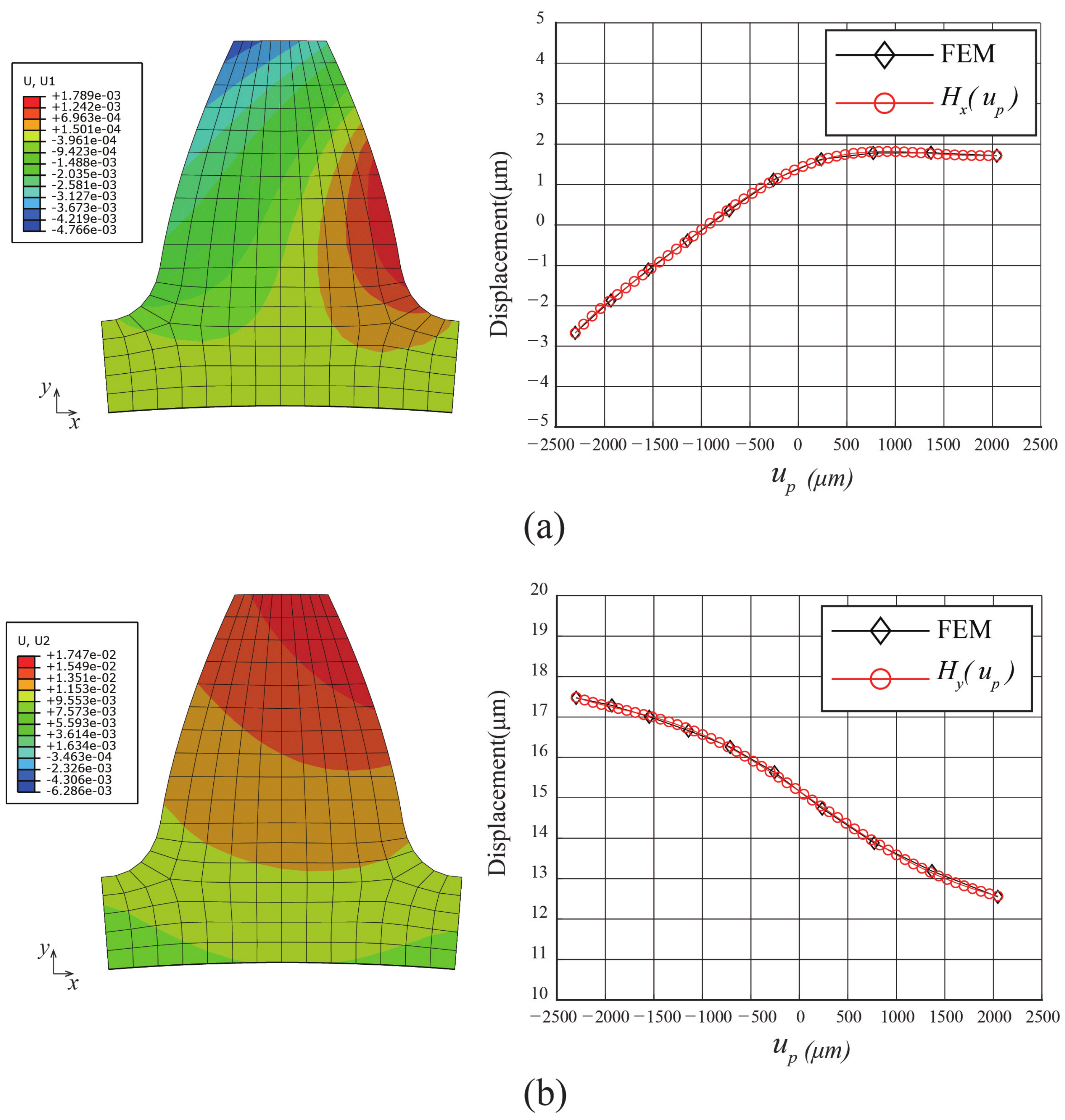
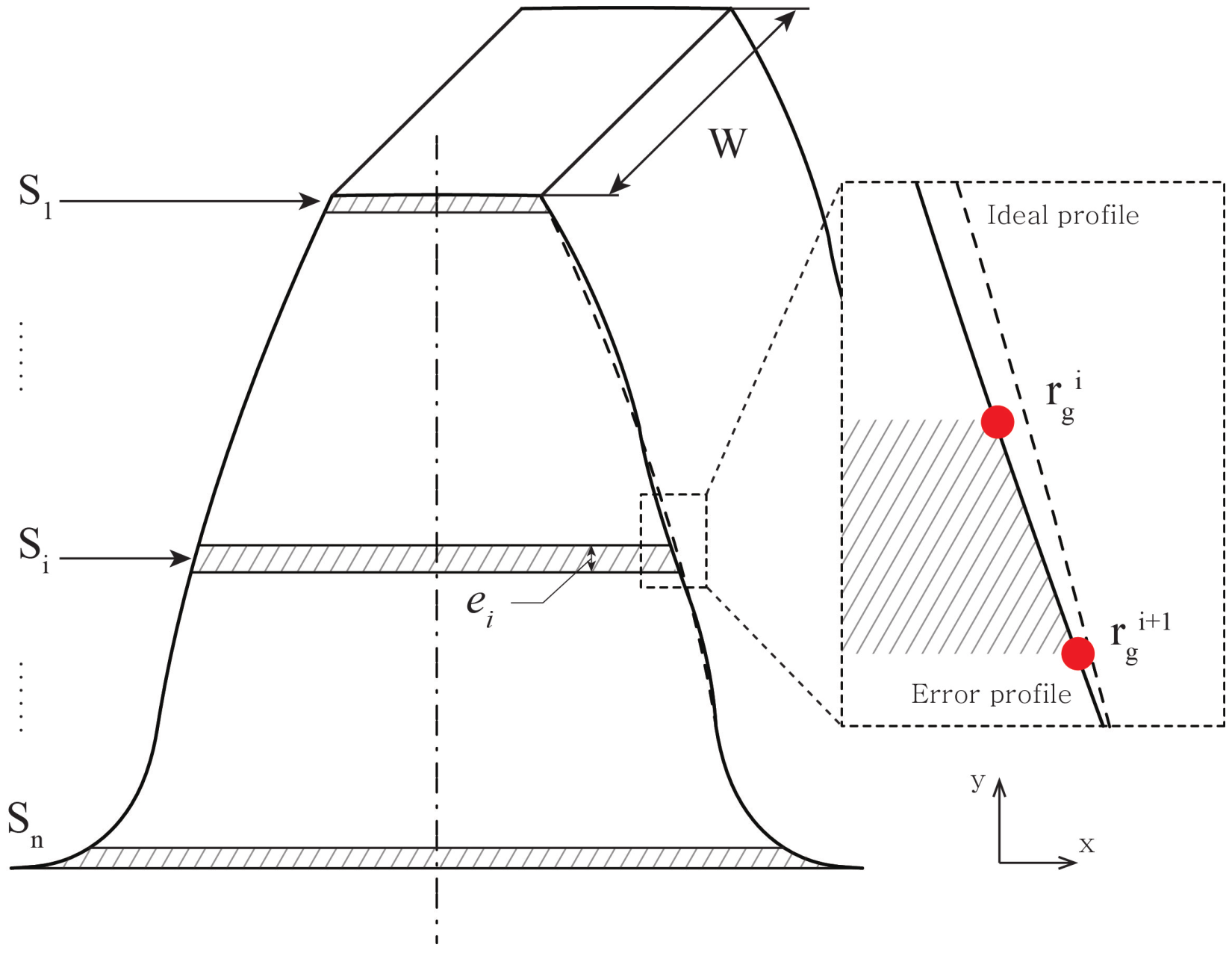
3.2. Thermal Deformation Uncertainties

In this study, we assume that either mechanical uncertainties or thermal deformation can influence geometric errors in gears. While mechanical uncertainties have been considered as an important factor affecting the performance of gear pairs (or systems), thermal deformation has been relatively less studied and ignored in most previous works [9,10]. Relative significance of the two types of uncertainties depends on the material properties. For example, in steel gears, thermal deformation barely changes geometric errors, and the impact of mechanical uncertainties is dominant. On the other hand, thermal deformation can be more influential than mechanical uncertainties. Figure 6 shows the geometric error induced from the machining error (black) and from thermal deformation (red), respectively, when a plastic gear operates at 200 RPM under 20 Nm. We use the machining error described in Section 3.1 when ϵ = 4 . The implementation of thermal deformation is described in the remainder of this section. Here, we consider deterministic thermal deformation, i.e., η = 0 ; see Equation (17) below. Figure 6 exhibits that thermal deformation can lead to higher geometric error than machining error in the case of a plastic gear, which is unlikely to happen in steel gears.
Friction between the gear meshing surfaces makes a gear pair operate and continuously generates heat on the tooth surface. The frictional heat increases the temperature of the gear pair, resulting in thermal deformation of the gear tooth. To estimate the thermal deformation, we measure the change in displacement of a gear tooth at the temporal steady-state when heat transfer is complete. By performing FE analysis at the steady-state, we estimate the transition of displacement from the initial state. The displacement change depends on the thermal expansion coefficient and steady-state temperature. To clarify, we consider the frictional heat as the only heat source and assume that the operating conditions such as torque, speed, lubrication, and ambient temperature are given a priori following the design process of the entire system. The heat convection parameters used in thermal analysis are constant values that are determined according to the lubrication condition and operation environment. Thus, when the frictional heat is constant, material properties are the only factors that determine the steady-state temperature and the displacement change. In this study, we assume randomnesses in five essential material properties, i.e., Young’s modulus, thermal expansion coefficient, density, conductivity, and specific heat capacity, to investigate the uncertain thermal deformation. All material properties are assumed to follow uniform distributions within the ranges
μ i [ μ i * ( 1 η ) , μ i * ( 1 + η ) ] , ( μ 1 * : Y o u n g s m o d u l u s , μ 2 * : t h e r m a l e x p a n s i o n c o e f f i c i e n t , μ 3 * : d e n s i t y , μ 4 * : c o n d u c t i v i t y , μ 5 * : s p e c i f i c h e a t c a p a c i t y ) .
Here, μ i represents each material property with uncertainty, and η denotes the size of the uncertainties of the material properties.
Frictional heat is related to the contact stress and relative sliding speed, which depends on where the contact occurs. Each position of the gear tooth has a different temperature when the gear pair reaches a steady state. Thus, the gear has a different shape compared to the involute curve after thermal deformation. Rolling friction, friction caused by deformation, and sliding friction are the three main aspects of the frictional heat generated between the gear meshing surfaces [28]. Rolling friction and friction caused by deformation have a negligible effect on heat generation. Therefore, only sliding friction is considered to predict the frictional heat. The sliding friction is determined by the contact stress, relative sliding speed, and friction coefficient between the gear meshing surfaces. The frictional heat at each contact point is used for thermal analysis based on the FEM [29].
The thermal deformation in the steady state is measured by the nodal displacements of the tooth surface in the coordinate system C c . Here, U x and U y denote the x - and y - directional nodal displacements, respectively. The nodal displacements U x and U y can be expressed in terms of u p , the x-coordinate in C p , using the relationship between u c and u p in Equation (16).
To construct continuous displacement curves of the thermal deformation, we interpolate the discrete nodal displacements U x and U y . Note that the profile of the gear surface consists of ( n + 1 ) nodes, whose nodal positions are denoted by u p i in the coordinate system C p , i = 0 , 1 , , n . We denote the nodal displacements U x and U y at u p = u p i by U x i and U y i , respectively. Figure 7 (black diamonds) shows the discrete nodal displacements U x i and U y i , i = 0 , 1 , , n . By using the monomial polynomials u p j , j = 0 , 1 , , n , the displacement curves of thermal deformation in the x - and y - directions, denoted by H x and H y , respectively, can be expressed as
H x ( u p ) = j = 0 n a j x u p j , H y ( u p ) = j = 0 n a j y u p j ,
where   
1 u p 0 u p 0 2 u p 0 n 1 u p 1 u p 1 2 u p 1 n 1 u p n u p n 2 u p n n a 0 x a 1 x a n x = U x 0 U x 1 U x n , 1 u p 0 u p 0 2 u p 0 n 1 u p 1 u p 1 2 u p 1 n 1 u p n u p n 2 u p n n a 0 y a 1 y a n y = U y 0 U y 1 U y n .
Figure 7 (red circles) shows the interpolation curves for the thermal deformations, i.e., H x ( u p ) and H y ( u p ) .
To represent the gear geometry with thermal deformation, the continuous curves H x and H y should be considered in the mathematical method for designing cylindrical gears. The position vector r T , which expresses the gear geometry with thermal deformation, is represented as
r T ( u p , ϕ p , θ p ) = M T r g ( u p , ϕ p , θ p ) , M T = 1 0 0 H x ( u p ) 0 1 0 H y ( u p ) 0 0 1 0 0 0 0 1 ,
where M T is a transformation matrix used to consider the effect of thermal deformation.

4. Statistical Analysis for Gear System with Uncertainties

For statistical analysis, we generated spur gear pairs with mechanical uncertainties and thermal deformation and calculated the TE of a spur gear pair using LTCA. The deterministic LTCA is described in Section 2.2. The transmission error Δ ψ L under the loaded condition is the sum of the transmission errors Δ ψ U under the unloaded condition and elastic deflection δ E , where both Δ ψ U and δ E are affected by uncertainties. Further, Δ ψ U is calculated using the TCA of the spur gear pair, which has a profile with uncertainties, and δ E is calculated using the gear profile and material properties that have uncertainties.
To measure and analyze the responses of a spur gear pair with comprehensive uncertainties, we performed Monte Carlo (MC) simulation [30,31,32]. For this purpose, we varied the main uncertain parameters e a (Equation (13)), ϵ (Equation (14)), and η (Equation (17)), and generated each MC sample by following the Latin hypercube sampling (LHS) method [33,34]. The detailed algorithm for the MC simulation for generating spur gear pairs is described in Section 4.2.

4.1. LTCA for Gear System with Uncertainties

To calculate the transmission error Δ ψ U under the unloaded condition, we considered the gear profile with uncertainties. The equation of meshing satisfied by the envelope of the family of rack cutter surfaces cannot be rearranged as an explicit function because of the uncertainties of the rack cutter surface. Therefore, we need to consider the equation of meshing as an additional condition along with the kinematic conditions (8) satisfied at the contact points, which results in three kinematic conditions:
S e 1 S e 2 = 0 , N e 1 × N e 2 = 0 , ( r p i * u p × r p i * θ p ) · r p i * ϕ p = 0 ( i = 1 , 2 ) ,
where
S e 1 ( u p 1 , ϕ p 1 , θ p 1 , ψ 1 ) = cos ψ 1 sin ψ 1 0 0 sin ψ 1 cos ψ 1 0 0 0 0 1 0 0 0 0 1 r T 1 , S e 2 ( u p 2 , ϕ p 2 , θ p 2 , ψ 2 ) = cos ψ 2 sin ψ 2 0 0 sin ψ 2 cos ψ 2 0 d g 0 0 1 0 0 0 0 1 r T 2 , N e i = S e i * u p × S e i * θ p , ( i = 1 , 2 ) .
Here, S e i , N e i , r p i , and r T i ( i = 1 , 2 ) are the position vector, normal vector of the gear surface with uncertainties in C s i , position vector of the gear surface in C p , and position vector of the gear surface with thermal deformation in C g , respectively. The subscripts i = 1 , 2 denote driving and driven gears, respectively. Further, S e 1 * , S e 2 * , and r p * are vectors obtained by eliminating the last elements of S e 1 , S e 2 , and r p , respectively. To simplify Equation (21), we assume that there is no variation on gear surface in the z-axis, the longitudianl direction of gear. Note that parameter θ p , the z-coordinate of the position vector r p , can be eliminated as following the 2D simplification. From Equation (21), five equations P e i ( i = 1 , 2 , 3 , 4 , 5 ) are derived:
P e 1 ( u p 1 , ϕ 1 , ψ 1 , u p 2 , ϕ 2 , ψ 2 ) = ( S e 1 S e 2 ) · i = 0 , P e 2 ( u p 1 , ϕ 1 , ψ 1 , u p 2 , ϕ 2 , ψ 2 ) = ( S e 1 S e 2 ) · j = 0 , P e 3 ( u p 1 , ϕ 1 , ψ 1 , u p 2 , ϕ 2 , ψ 2 ) = ( N e 1 × N e 2 ) · k = 0 , P e 4 ( u p 1 , ϕ 1 ) = ( r p 1 * u p 1 × r p 1 * θ p 1 ) · r p 1 * ϕ p 1 = 0 , P e 5 ( u p 2 , ϕ 2 ) = ( r p 2 * u p 2 × r p 2 * θ p 2 ) · r p 2 * ϕ p 2 = 0 .
Using the Newton–Raphson method, we can obtain the six unknown parameters ( u p 1 , ϕ 1 , ψ 1 , u p 2 , ϕ 2 , and ψ 2 ) that satisfy Equation (23).
The elastic deflection δ E is affected by the gear profile, material properties, and applied load. However, to focus on gear profile and material properties related to uncertainties, we exclude the load sharing effect in this study. The mesh stiffness changes according to the contact zone, the shape of the profile, and elastic modulus. Thus, we consider the uncertainties in the gear profiles and elastic modulus when calculating the bending deflection δ b e , fillet-foundation deflection δ f e , and contact deflection δ h e , all of which together determine the elastic deflection δ E .
The gear profile with uncertainties consists of ( n + 1 ) points, and the ith point is expressed as r g i , as shown in Figure 8. A gear tooth is regarded as a nonuniform cantilever beam to calculate the bending deflection. The position of r g i is used to measure the area of the tooth cross section S i and the area moment of inertia from the nonuniform cantilever beam. The gear profile changed by the uncertainties affects the contact zone, which can be obtained using Equation (23) of the gear system. The contact zone changes the area where the force is applied and thus determines the bending deflection. The three deflections can be written as
δ b e = F cos 2 α m i = 0 n e i d i e i d i + 1 3 e i 2 E I ¯ i e + 1 s h G A ¯ i e + tan 2 α m A ¯ i e E , δ f e = F cos 2 α m W E e L * ( u f S f ) 2 + M * u f S f + P * ( 1 + Q * tan 2 α m ) , δ h e = 2 F ( E 1 e + E 2 e ) ( 1 ν 2 ) π W E 1 e E 2 e , E = E e ( 1 ν ) ( 1 + ν ) ( 1 2 ν ) , 1 / I ¯ i e = ( 1 / I i + 1 / I i + 1 ) / 2 , 1 / A ¯ i e = ( 1 / A i + 1 / A i + 1 ) / 2 ,
where E e , A ¯ i e , and I ¯ i e are the elastic modulus, area of the tooth cross section S i , and area moment of inertia, respectively, each with uncertainties. The detailed notations are described in Appendix A.
The mesh stiffness K m e s h i n g e of the spur gear pair with uncertainties is expressed as
K m e s h i n g e = 1 / 1 k b 1 e + 1 k f 1 e + 1 k b 2 e + 1 k f 2 e + 1 k h e , k b e = F δ b e , k f e = F δ f e , k h e = F δ h e ,
where k b 1 e and k b 2 e are the bending stiffness of the driving and driven gears, respectively, with uncertainties. k f 1 e and k f 2 e are the fillet-foundation stiffnesses of the driving and driven gears, respectively, with uncertainties.

4.2. Monte Carlo (MC) Simulation

Monte Carlo (MC) simulation was used to evaluate the effects of the respective uncertainties on the transmission error. The uncertainties in the pitch, machining, and material properties are characterized by the parameters E p , ϵ , and η , respectively. The parameters indicate the range or magnitude of the respective uncertainties. To estimate the influence of these uncertainties on the spur gear pair, we generated gear model samples under a randomly given pair ( E a , ϵ , η ) .
Specifically, for the pitch uncertainty, we randomly choose N values of e p i [ E p , E p ] , ( i = 1 , 2 , , N ) , for a given uncertainty parameter E p > 0 . From Equation (13), the movement of the rack cutter ϕ g is measured for each e p i .
Second, to obtain the rack cutter profile samples in which machining uncertainty is considered, we adopt the Latin hypercube sampling (LHS) method [33,34]. It is known that LHS exhibits a faster rate of convergence than a simple random sampling method. For a given machining uncertainty parameter ϵ > 0 , the LHS operates by dividing the uncertainty ranges into non-overlapping subspaces of equal size and obtains a random point from each subspace. Figure 9 shows an example of the sampling for the machining uncertainty. Here, we suppose that ϵ = 1 and divide the X , Y axes into m s u b ( = 8 ) subspaces of equal size. Out of m s u b 2 subspaces in R 2 , we choose m s u b subspaces such that their rows and columns are not overlapping with each other. In each subspace, a point is randomly selected. Then, as described in Section 3.1 and Figure 5, we obtain a rack cutter profile sample by interpolating these points. For a fixed ϵ > 0 , we can generate N different sets of points from the LHS subspaces, which leads to N rack cutter profile samples. In the numerical tests, we use a fixed number of subspaces for the LHS sampling m s u b = 8 ; see Algorithms 1 and 2 and Section 5.
Finally, to calculate the geometric error of thermal deformation, uncertainties in the material properties are considered. Five material properties ( μ 1 : Young s modulus , μ 2 : thermal expansion coefficient , μ 3 : density , μ 4 : conductivity , μ 5 : specific heat capacity ) generated randomly within a given range [ μ i ( 1 η ) , μ i ( 1 + η ) ] , ( i = 1 , 2 , , N ) were used for the thermal analysis. We can obtain data on the geometric error generated by thermal deformation through thermal analysis using FEM. Two types of materials (steel and plastic) were considered to investigate the influence of thermal deformation on the transmission error.
In summary, from a given pair ( E a , ϵ , η ) , we have N samples of gear models in which all three types of uncertainties are considered. The pitch and machining uncertainties are related to the N rack cutter samples and their movements. Through the rack cutters, the corresponding N gear profiles are generated, where the displacement due to thermal deformation is affected by the material property.
After obtaining the N gear model samples, we combine them with each other and generate N ( N 1 ) / 2 gear systems with uncertainties. Then, LTCA is conducted to calculate the transmission error under the loaded condition. Depending on which gears are combined and the related uncertainties, the spur gear pair exhibits different transmission errors. Detailed algorithms for obtaining N ( N 1 ) / 2 spur gear pair samples for given uncertainty parameters ( E a , ϵ , η ) are described in Algorithms 1 and 2.
Based on the spur gear pair samples with uncertainties, we performed statistical analysis of the corresponding transmission errors.
Algorithm 1 Gear model sampling with uncertainties.
 
   Inputs:
1: 
E p : pitch uncertainty parameter
2: 
ϵ : machining uncertainty parameter
3: 
η : material properties uncertainty parameter
4: 
N: number of gear model samples
5: 
{ μ k } : set of material properties of the gear material considered
( μ 1 = Young’s modulus, μ 2 is the coefficient of thermal expansion, μ 3 = density, μ 4 = conductivity,
μ 5 = heat capacity)
 
6: 
for i = 1 to N
7: 
     [Step 1: Generate rack cutter profiles with machining uncertainty]
8: 
     Let m s u b = 8 .
9: 
     Get m s u b Latin hypercube sampling (LHS) samples from [ m i n ( u p ) , m a x ( u p ) ] × .
[ ϵ , ϵ ] R 2 .
10:
    Define a rack cutter profile f i by the interpolation of m s u b LHS samples using
Lagrange polynomials.
 
11:
     [Step 2: Generate rack cutter movements with pitch uncertainty]
12:
     Randomly select e p i [ E p , E p ] .
13:
     Measure the rack cutter movement ϕ g i = ( ϕ c / d c ) + e p i .
 
14:
     [Step 3: Generate material properties with uncertainty]
15:
     for  k = 1 to 5
16:
         Randomly select μ k i [ μ k ( 1 η ) , μ k ( 1 + η ) ] .
17:
     end for
18:
      μ i = [ μ 1 i , μ 2 i , μ 3 i , μ 4 i , μ 5 i ] .
 
19:
     [Step 4: Generate N gear models]
20:
     Generate a gear model G i considering the rack cutter f i , its movement ϕ g i ,
     and the material properties μ i .
 
21:
     [Step 5: Analyze the displacement due to thermal deformation]
22:
      d t i = Thermal analysis ( G i )
23:
end for
 
 
    Outputs:
24:
Gear model samples { G i : i = 1 , 2 , · , N } .
25:
Displacement due to thermal deformation of each gear model sample { d t i : i =
1 , 2 , · , N } .
Algorithm 2 Gear pair sampling.
 
  Inputs:
1:
{ G i : i = 1 , 2 , , N } : gear model samples.
2:
{ d t i : i = 1 , 2 , · , N } : Displacement due to thermal deformation of gear model sample.
 
Iteration of LTCA
3:
for i = 1 to ( N 1 )
4:
    for  j = ( i + 1 ) to N
5:
         Δ ψ i j U = TCA( G i , G j , d t i , d t j )
6:
         δ i j E = Mesh stiffness( G i , G j )
7:
         Δ ψ i j L = Δ ψ i j U + δ i j E
8:
    end for
9:
end for
 
 
  Output:
10:
Transmission errors of gear systems Δ ψ i j L

5. Numerical Studies

The influences of the mechanical uncertainties and thermal deformation on the transmission errors of a spur gear pair were examined using the proposed method with numerical examples. The tooth contact analysis of numerical examples is under 2D simplification, and we focus on studying the influence of uncertainties on 2D spur gear pairs. We considered three numerical examples for investigating the influences of the uncertainties and transmission errors with a comprehensive error. Table 1 summarizes the design parameters and material properties of the spur gear pair used in the numerical example. There are two cases of gear pairs, i.e., steel and plastic. For lubrication, we consider its effect on the steel gear pairs only since, in general, plastic gear pairs do not use lubrication due to material characteristics.

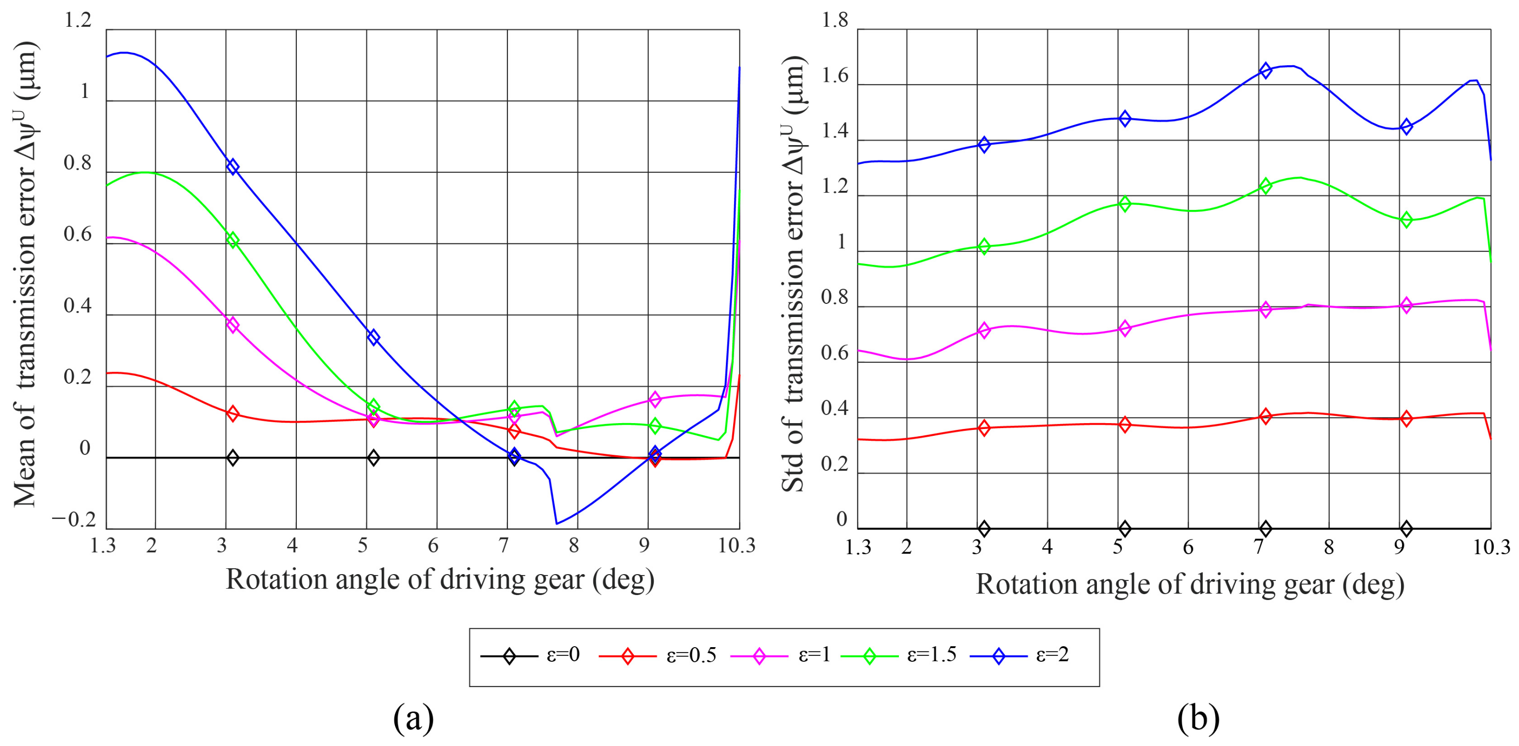
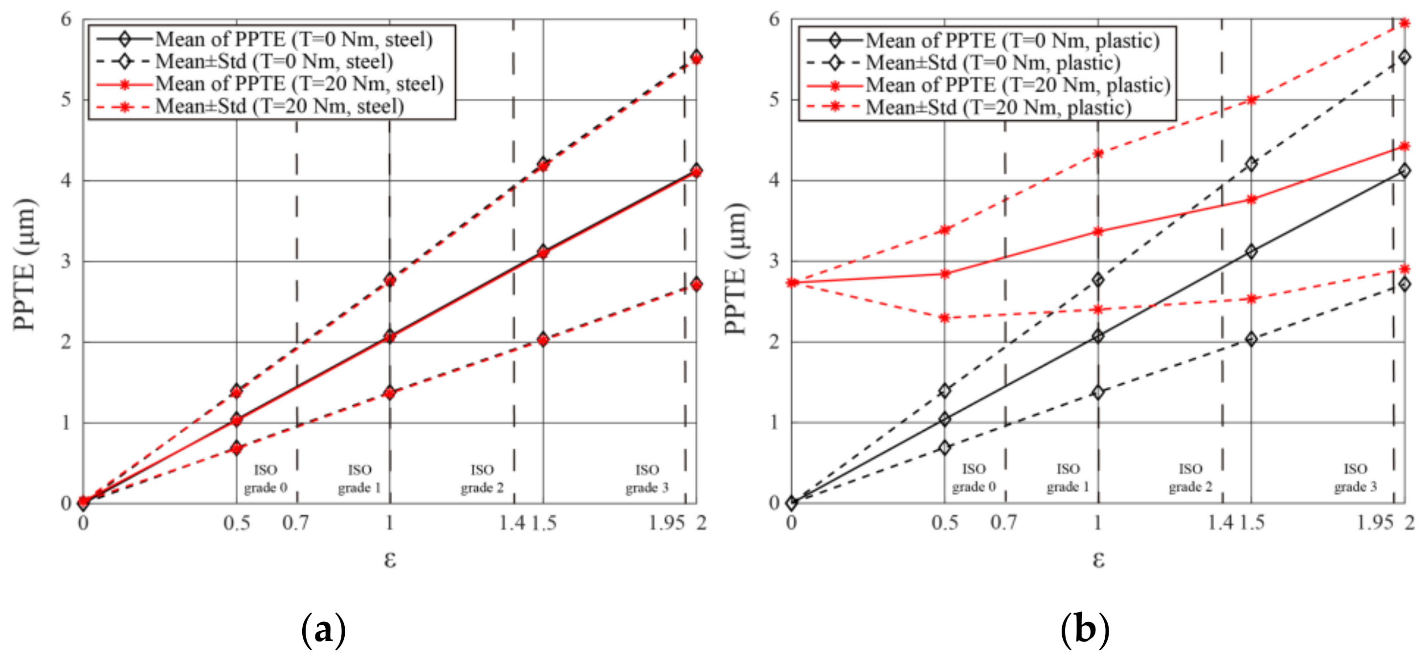
5.1. Effect of Machining Error (ME) on Transmission Error (TE)

Thermal deformation and pitch error are not considered as uncertainties in this example. To study the influence of the machining error on the transmission error, the mean and standard deviation of the transmission error are analyzed under unloaded and loaded conditions.
The mean and standard deviation of the transmission error under the unloaded condition are shown in Figure 10. The performance of the spur gear pair under the unloaded condition is affected by the shape of the tooth profile. When ϵ = 0 , the tooth profile is an ideal involute curve, and the spur gear pair has no transmission error. As ϵ increases, the fluctuation of the transmission error increases, which can be confirmed as shown in Figure 10. Figure 11 shows the mean and standard deviation of the transmission error under the loaded condition. The plastic spur gear pair has larger fluctuations than the steel spur gear pair in both the mean and the standard deviation of the transmission error because plastic has lower stiffness than steel. Furthermore, there is a difference in the tendency of the transmission error. The transmission error of the steel spur gear pair is similar to the transmission error under the unloaded condition, whereas that of the plastic spur gear pair is not. This implies that plastic is susceptible to applied force. As ϵ increases, the standard deviation of the peak-to-peak transmission error (PPTE) increases. From Figure 12, the range of the PPTE of the designed spur gear pair can be predicted. The machining error under 2D simplification can be compared with total profile deviation, which is one of the factors in ISO precision grade. It is possible to calculate the level of machining error required to satisfy the transmission error of the desired gear quality.

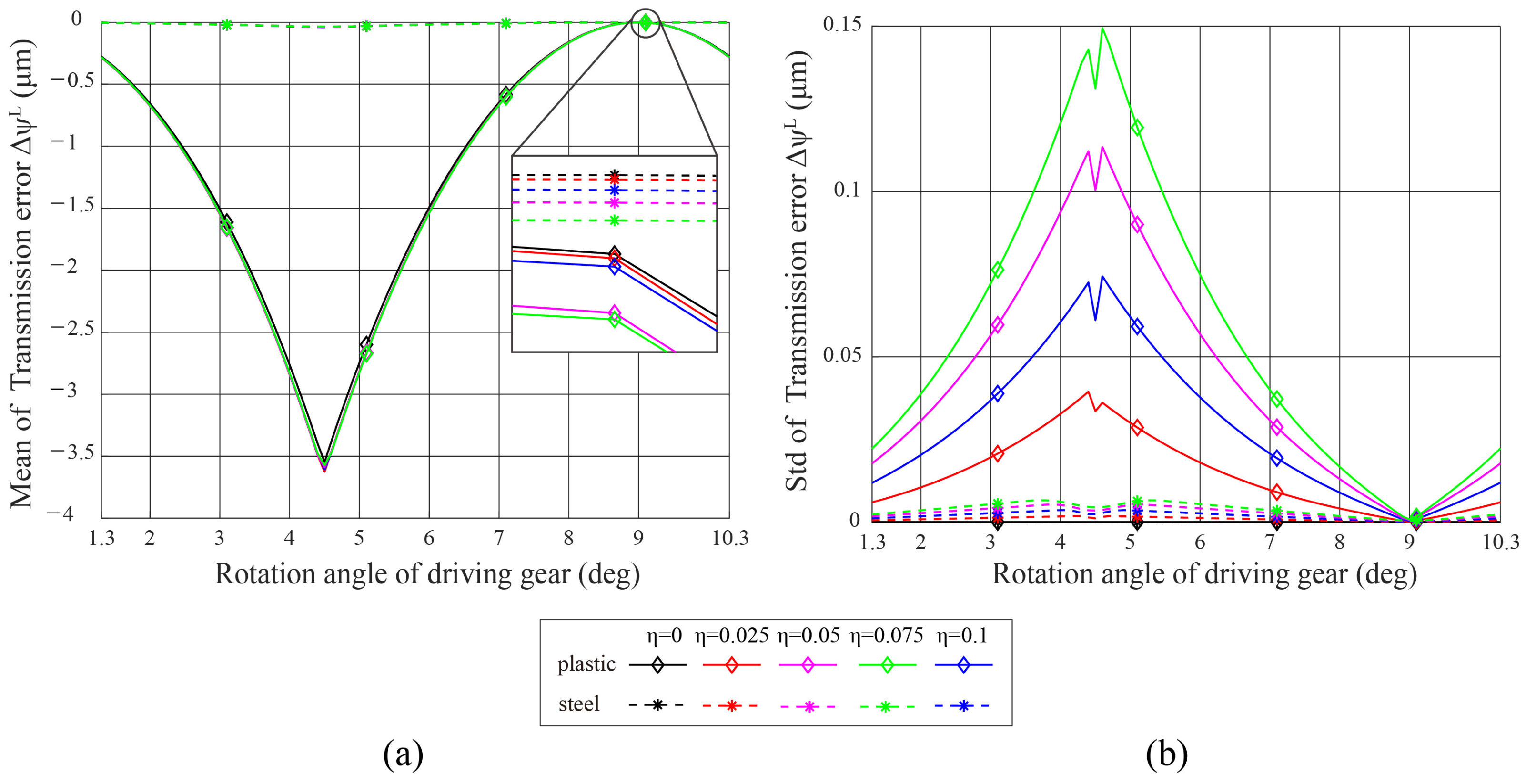
5.2. Effect of Thermal Deformation (TD) on Transmission Error (TE)

In this example, LTCA is conducted on a spur gear pair with thermal deformation under unloaded and loaded conditions to study the transmission error. To compare the influence of thermal deformation on the transmission error between the spur gear pairs with different materials, TCA was conducted on steel and plastic, and the mechanical uncertainty was not considered.
The transmission error of the spur gear pair under the unloaded condition was generated by the geometric error caused by thermal deformation. The difference in transmission error between steel and plastic gear pairs results from the difference in material properties. From Figure 13, it is found that the plastic spur gear pair is more susceptible to thermal deformation than the steel spur gear pair. When η increases, the increase in the standard deviation of the plastic spur gear pair is larger than that of the steel spur gear pair. This difference becomes larger under the loaded condition. The standard deviation of the steel spur gear pair under the loaded condition is similar to that under the unloaded condition, whereas that of the plastic spur gear pair increases by approximately two times, as shown in Figure 14. The PPTE generated by thermal deformation is similar regardless of the size of η . As η increases, the standard deviation of the PPTE of the steel and plastic spur gear pairs tends to increase; however, it is not as large as the standard deviation of the machining error, as shown in Figure 15. The more precise the spur gear pairs with smaller machining errors, the greater is the transmission error generated by thermal deformation. When we design a spur gear pair with a material that is susceptible to thermal deformation, considering the range of the transmission error expected during operation will be useful for a safer and more precise design.

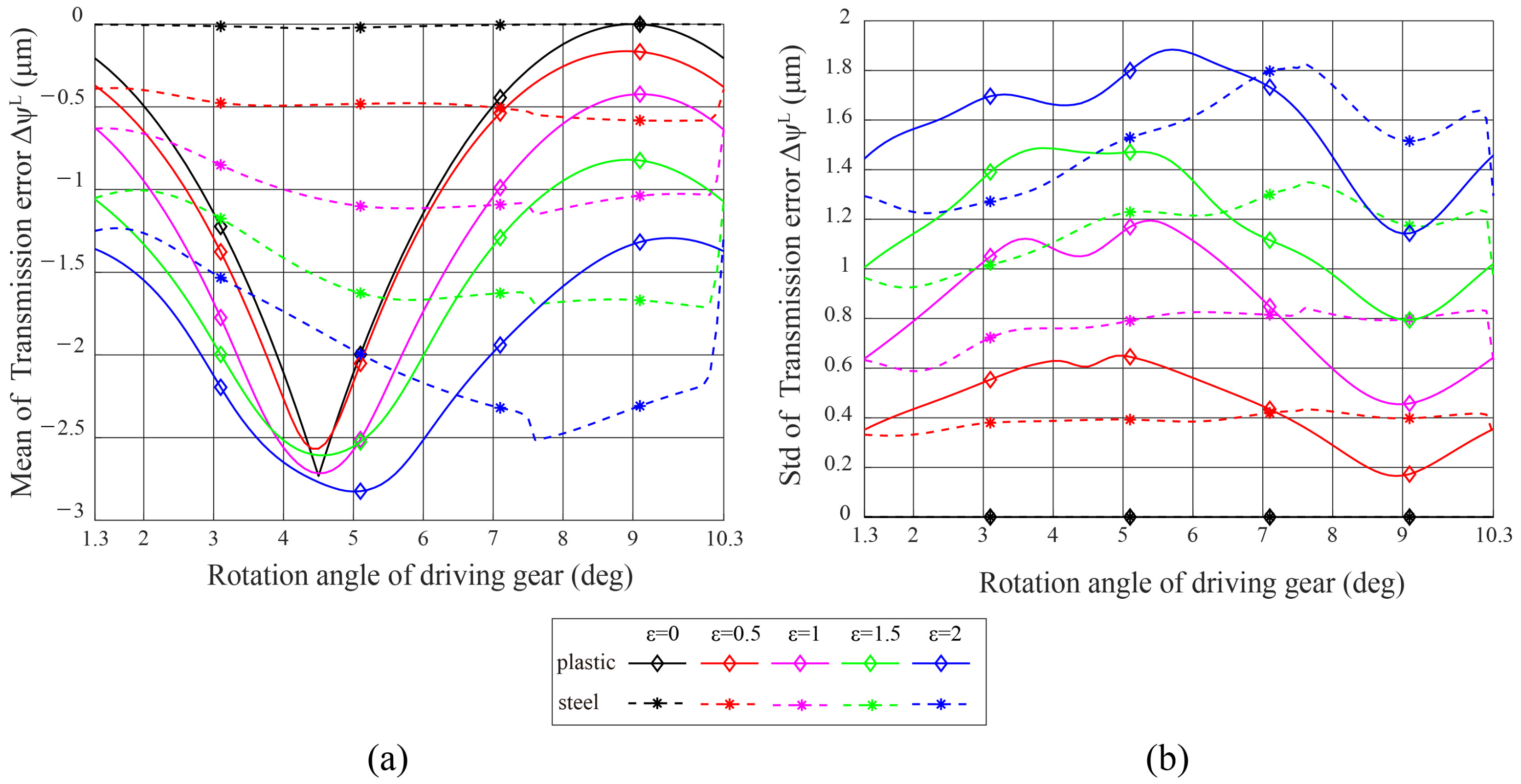
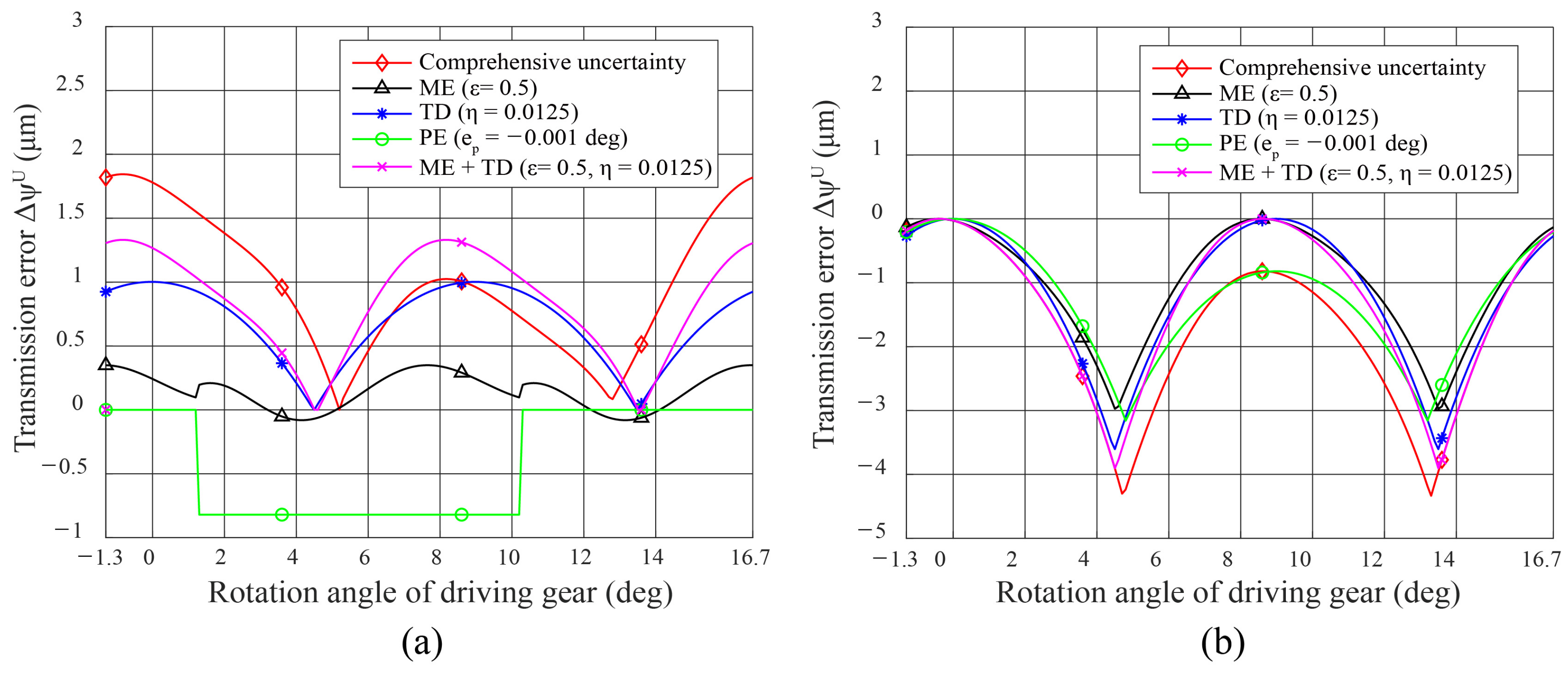
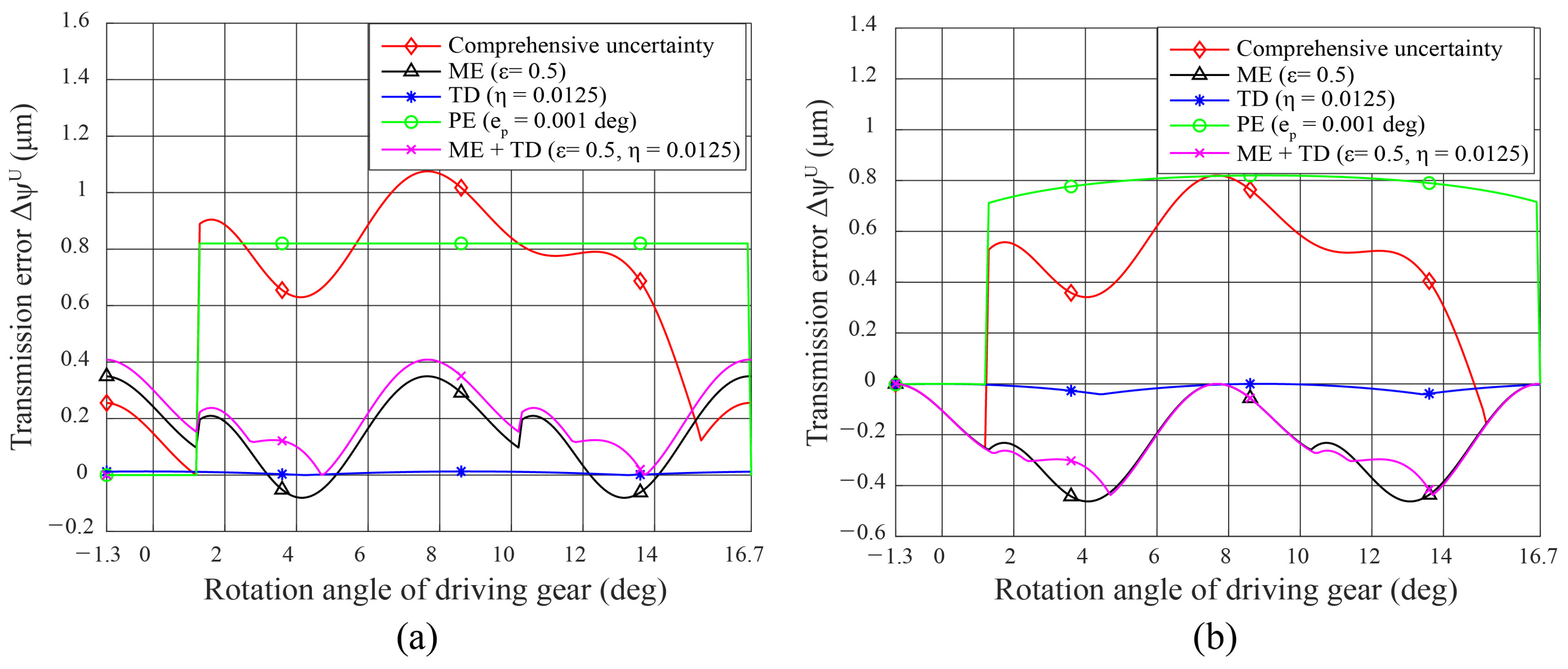
5.3. Effect of Comprehensive Error on Transmission Error (TE)

A spur gear pair with a comprehensive error consisting of a machining error, thermal deformation, and a pitch error is generated, and LTCA is conducted on plastic and steel. Figure 16, Figure 17, Figure 18 and Figure 19 show the transmission errors of the spur gear pair as one of the samples. Samples of the spur gear pair have a machining error ( ϵ = 0.5 ), thermal deformation ( η = 0.0125 ), and a pitch error e p . The pitch error of the driving gear is e p = 0.001 deg in Figure 16 and Figure 17 and e p = 0.001 deg in Figure 18 and Figure 19. The driven gear has no pitch error.
Transmission errors with a comprehensive error under unloaded and loaded conditions are calculated to be larger than the transmission errors of the three uncertainties. In the case of a steel gear under the unloaded condition, the transmission error with thermal deformation is the smallest among the three uncertainties. Although the transmission error caused by only thermal deformation is small, thermal deformation coupled with mechanical uncertainties causes a significant transmission error. When thermal deformation is coupled with other uncertainties, it has a more considerable impact on the transmission error than magnitude. From Figure 16 and Figure 17, it is found that the effect of the interaction of thermal deformation is different according to the material properties. The effect of the interaction of each uncertainty is clearly shown in Figure 20. There is a difference between the comprehensive uncertainty (red line) and the linear sum of each uncertainty (blue line). Note that the effect of the interaction of each uncertainty leads to the difference between the geometric error of the comprehensive uncertainty and the linear sum of each uncertainty. In the case of a plastic gear under the unloaded condition, the tendency of the transmission error with the comprehensive error is similar to that of thermal deformation. From this fact, it is found that thermal deformation has the greatest effect on the transmission error among the three uncertainties. In the case of a plastic gear under the loaded condition, all transmission errors with uncertainty have similar tendencies owing to elastic deflection. The gear tooth, which has a pitch error, causes an error in the tooth contact pattern. When the gear tooth contact is late or early, the difference in the contact pattern appears as a transmission error. From comparison between Figure 16 and Figure 17 (or Figure 18 and Figure 19), it is found that the magnitude of pitch error affects the major tendency of transmission error, not a detailed waveform.

6. Conclusions

We proposed an analytical method that calculates the TE of a spur gear pair by considering various materials and statistically analyzed the range of the TE caused by various uncertainties. In contrast to the conventional approach, which considers only the mechanical uncertainty, we additionally considered the thermal deformation for tooth contact analysis. This approach is appropriate in that thermal deformation can generate a large geometric error according to the material. To demonstrate the importance of the geometric error caused by thermal deformation, the magnitudes of geometric errors caused by mechanical uncertainty and thermal deformation were compared in the case of a plastic gear. Through various numerical examples, we investigated the tendency and influence of each uncertainty on the TE. We believe that considering the uncertainties can lead to more precise gear design in terms of predicting the performance range and managing the gear quality. Although steel gears are not susceptible to thermal deformation, we demonstrated that the TE of a spur gear pair with a comprehensive error is greater than that of a spur gear pair with mechanical uncertainties due to thermal deformation. In this study, we only investigated a numerical method that calculates the TE of a spur gear pair with uncertainties. However, this approach should be validated experimentally, and the influence of thermal deformation on the TE should be examined using the proposed method. Furthermore, the proposed method can be extended to other gear systems, such as helical, worm, and harmonic drive systems, since the approach is based on the kinematic relationship between the rack and the gear. Studying spur gear pairs that are susceptible to uncertainties in the tooth geometry is an important direction for future research.

Author Contributions

Conceptualization and numerical analysis, J.-H.L., H.-S.C., and J.-G.K.; writing–original draft preparation, J.-H.L., H.-S.C.; writing—review and editing, J.-G.K., J.-H.S., G.-H.L., D.-I.P.; funding acquisition, D.-I.P. All authors have read and agreed to the published version of the manuscript.

Funding

This research was funded by the Technology Innovation Program NO.1415168894 supported by the Ministry of Trade, Industry and Energy of the Korean Government.

Institutional Review Board Statement

Not applicable.

Informed Consent Statement

Not applicable.

Data Availability Statement

Data available on request due to privacy/ethical restrictions. The data presented in this study are available on request from the corresponding authors. The data are not publicly available due to their containing information that could compromise the privacy of research participants.

Conflicts of Interest

The authors declare no conflict of interest. The funders had no role in the design of the study; in the collection, analyses, or interpretation of data; in the writing of the manuscript, or in the decision to publish the results.

Appendix A. Mesh Stiffness

Here, as in [35], a tooth is regarded as a nonuniform cantilever beam to calculate the bending deflection δ b :
δ b = F cos 2 α m i = 1 n e i d i e i d i + 1 3 e i 2 E I ¯ i + 1 s h G A ¯ i + tan 2 α m A ¯ i E , E = E ( 1 ν ) ( 1 + ν ) ( 1 2 ν ) , 1 / I ¯ i = ( 1 / I i + 1 / I i + 1 ) / 2 , 1 / A ¯ i = ( 1 / A i + 1 / A i + 1 ) / 2 .
Here, F is the applied force, α m is the operating pressure angle, G is the shear modulus, s h is a shear factor, e i and d i are illustrated in Figure A1, I i is the area moment of inertia, A i is the area of the tooth cross section S i , E is Young’s modulus, and ν is Poisson’s ratio.
Figure A1. Nonuniform cantilever beam gear model.
Applsci 11 06582 g0a1
The equation for the fillet-foundation deflection δ f is based on Muskhelishvili’s theory, which was enhanced by Sainsot [36,37]. By assuming a linear distribution of the normal stress and a constant shear stress at the tooth root, the gear-body-induced tooth deflection can be calculated analytically as
δ f = F cos 2 α m W E L * ( u f S f ) 2 + M * u f S f + P * ( 1 + Q * tan 2 α m ) , X i * ( h f i , θ f ) = A i / θ f 2 + B i h f i 2 + C i h f i θ f + D i θ f + E i h f i + F i , h f i = r d e d e n d u m r i n n e r .
Here, W is the tooth width, while u f , S f , h f i , and θ f are given in Figure A1. Further, A i , B i , C i , D i , E i , and F i are given in Table A1, while X i * represents the coefficients L i * , M i * , P i * , and Q i * .
Table A1. Values of the coefficients of Equation (A2).
A i A i B i C i D i E i F i
L * ( h f i , θ f ) −5.574 × 10 5 −1.9986 × 10 3 −2.3015 × 10 4 4.7702 × 10 3 0.02716.8045
M * ( h f i , θ f ) 60.111 × 10 5 28.100 × 10 3 −83.431 × 10 4 −9.9256 × 10 3 0.16240.9086
P * ( h f i , θ f ) −50.952 × 10 5 185.50 × 10 3 0.0538 × 10 4 53.300 × 10 3 0.28950.9236
Q * ( h f i , θ f ) −6.2042 × 10 5 9.0889 × 10 3 −4.0964 × 10 4 7.8297 × 10 3 −0.14720.6904
From the results of [38], the contact stiffness is based on Hertzian 2D theory. According to Hertzian law, the two elastic bodies in contact can be approximated by two cylinders on the 2D plane. The contact stiffness is constant in longitudinal direction and along the entire line of action. The contact deflection δ h is given by
δ h = F 4 ( 1 ν 2 ) π E W .
The mesh stiffness is calculated by superimposing the various stiffnesses, namely bending stiffness, fillet-foundation stiffness, and contact stiffness, as
k b = F δ b , k f = F δ f , k h = F δ h K m e s h i n g = 1 / ( 1 k b 1 + 1 k f 1 + 1 k b 2 + 1 k f 2 + 1 k h ) , δ E = F K m e s h i n g .

References

  1. Krawiec, P.; Walus, K.; Warguła, Ł.; Adamiec, J. Wear evaluation of elements of V-belt transmission with the application of optical microscope. In Proceedings of the MATEC Web of Conferences Machine Modelling and Simulations, Sklené Teplice, Slovak Republic, 5–8 September 2017; Volume 157, p. 01009. [Google Scholar]
  2. Konczak, M.; Kukla, M.; Warguła, Ł.; Talaska, K. Determination of the vibration emission level for a chipper with combustion engine. In Proceedings of the IOP Conference Series: Materials Science and Engineering, Kazimierz Dolny, Poland, 21–23 November 2019; Volume 776, p. 012007. [Google Scholar]
  3. Tang, J.; Zhang, Y.; Shi, Z. Radial and tangential error analysis of double-flank gear measurement. Precis. Eng. 2018, 51, 552–563. [Google Scholar] [CrossRef]
  4. Sato, O.; Osawa, S.; Kondo, Y.; Komori, M.; Takatsuji, T. Calibration and uncertainty evaluation of single pitch deviation by multiple-measurement technique. Precis. Eng. 2010, 34, 156–163. [Google Scholar] [CrossRef]
  5. Krawiec, P.; Warguła, Ł.; Walus, K.; Adamiec, J. Wear evaluation study of the multiple grooved pulleys with optical method. In Proceedings of the MATEC Web of Conferences XXIII Polish-Slovak Scientific Conference on Machine Modelling and Simulations, Rydzyna, Poland, 4–7 September 2018; Volume 254, p. 01004. [Google Scholar]
  6. Krawiec, P.; Domek, G.; Warguła, Ł.; Walus, K.; Adamiec, J. The application of the optical system ATOS II for rapid prototyping methods of non-classical models of cogbelt pulleys. In Proceedings of the MATEC Web of Conference, Machine Modelling and Simulations, Sklené Teplice, Slovak Republic, 5–8 September 2018; Volume 157, p. 01010. [Google Scholar]
  7. Krawiec, P.; Grzelka, M.; Kroczak, J.; Domek, G.; Kolodziej, A. A proposal of measurement methodology and assessment of manufacturing methods of nontypical cog belt pulleys. Measurement 2019, 132, 182–190. [Google Scholar] [CrossRef]
  8. Krawiec, P.; Czarnecka-Komorowska, D.; Warguła, Ł.; Wojciechowski, S. Geometric Specification of Non-Circular Pulleys Made with Various Additive Manufacturing Techniques. Materials 2021, 14, 1682. [Google Scholar] [CrossRef]
  9. Li, S. Effects of machining errors, assembly errors and tooth modifications on loading capacity, load-sharing ratio and transmission error of a pair of spur gears. Mech. Mach. Theory 2007, 42, 698–726. [Google Scholar] [CrossRef]
  10. Lin, T.; He, Z. Analytical method for coupled transmission error of helical gear system with machining errors, assembly errors and tooth modifications. Mech. Syst. Signal Process. 2017, 91, 167–182. [Google Scholar] [CrossRef]
  11. Liu, J.P.; Shu, X.B.; Kanazawa, H.; Imaoka, K.; Mikkola, A.; Ren, G.X. A model order reduction method for the simulation of gear contacts based on Arbitrary Lagrangian Eulerian formulation. Comput. Methods Appl. Mech. Eng. 2018, 338, 68–96. [Google Scholar] [CrossRef]
  12. Litvin, F.L.; Seol, I.H.; Kim, D.; Lu, J.; Wang, A.G.; Egelja, A.; Zhao, X.; Handschuh, R.F. Kinematic and geometric models of gear drives. J. Mech. Des. 1996, 118, 544–550. [Google Scholar] [CrossRef]
  13. Litvin, F.L.; Hsiao, C.-L. Computerized simulation of meshing and contact of enveloping gear tooth surfaces. Comput. Methods Appl. Mech. Eng. 1993, 102, 337–366. [Google Scholar] [CrossRef]
  14. Chaari, F.; Fakhfakh, H.; Haddar, M. Analytical modelling of spur gear tooth crack and influence on gearmesh stiffness. Eur. J. Mech. A-Solids. 2009, 28, 461–468. [Google Scholar] [CrossRef]
  15. Chen, Z.; Zhou, Z.; Zhai, W.; Wang, K. Improved analytical calculation model of spur gear mesh excitations with tooth profile deviations. Mech. Mach. Theory 2020, 149, 103838. [Google Scholar] [CrossRef]
  16. Wang, C. Study on 3-D modification for reducing vibration of helical gear based on TCA technology, LTCA technology and system dynamics. Mech. Syst. Signal Process. 2020, 146, 106991. [Google Scholar] [CrossRef]
  17. Letzelter, E.; Guingand, M.; Vaujany, J.-P.; Schlosser, P. A new experimental approach for measuring thermal behaviour in the case of nylon 6/6 cylindrical gears. Polym. Test. 2010, 29, 1041–1051. [Google Scholar] [CrossRef]
  18. Mao, K.; Li, W.; Hooke, C.J.; Walton, D. Polymer gear surface thermal wear and its performance prediction. Tribol. Int. 2010, 43, 433–439. [Google Scholar] [CrossRef]
  19. Krawiec, P.; Różański, L.; Czarnecka-Komorowska, D.; Warguła1, Ł. Evaluation of the Thermal Stability and Surface Characteristics of Thermoplastic Polyurethane V-Belt. Materials 2020, 13, 1502. [Google Scholar] [CrossRef] [Green Version]
  20. Krawiec, P.; Warguła, Ł.; Różański, L. Diagnostics of the Thermal Condition of the Cable Gear Used in the Drive of a Wood Chipper. In Proceedings of the IOP Conference Series: Materials Science and Engineering, Lviv, Ukraine, 26–27 November 2020; Volume 1016, p. 012013. [Google Scholar]
  21. Kashyap, S.; Houser, D.; Smith, Z.; Selvaraj, S.; Casella, J.; Bradway, J. Methods of describing plastic gear geometry after a temperature change with application to the prediction of gear load distribution. In Proceedings of the ASME 2011 International Design Engineering Technical Conferences and Computers and Information in Engineering Conference, Washington, DC, USA, 28–31 August 2021; Volume 8. [Google Scholar]
  22. Sohn, J.; Park, N. Geometric interference in cylindrical worm gear drives using oversized hob to cut worm gears. Mech. Mach. Theory 2016, 100, 83–103. [Google Scholar] [CrossRef]
  23. Chen, Y.-C.; Cheng, Y.-H.; Tseng, J.-T.; Hsieh, K.-J. Study of a harmonic drive with involute profile flexspline by two-dimensional finite element analysis. Eng. Comput. 2017, 34, 2107–2130. [Google Scholar] [CrossRef]
  24. Litvin, F.L.; Fuentes, A. Gear Geometry and Applied Theory; Cambridge University Press: Cambridge, UK, 2004. [Google Scholar]
  25. Ypma, T.J. Historical development of the Newton–Raphson method. SIAM Rev. 1995, 37, 531–551. [Google Scholar] [CrossRef] [Green Version]
  26. Ben-Israel, A. A Newton–Raphson method for the solution of systems of equations. J. Math. Anal. Appl. 1966, 15, 243–252. [Google Scholar] [CrossRef] [Green Version]
  27. ISO 1328-1. Cylindrical Gears—ISO System of Flank Tolerance Classification Part 1: Definitions and Allowable Values of Deviations Relevant to Flanks of Gear Teeth. 2013. Available online: https://www.iso.org/obp/ui/#iso:std:iso:1328:-1:ed-2:v1:en (accessed on 1 June 2021).
  28. Li, W.; Zhai, P.; Ding, L. Analysis of thermal characteristic of spur/helical gear transmission. J. Therm. Sci. Eng. Appl. 2019, 11, 21003. [Google Scholar] [CrossRef]
  29. Abaqus Manual. Available online: http://dsk.ippt.pan.pl/docs/abaqus/v6.13/books/usi/default.htm (accessed on 1 June 2021).
  30. Zhang, H.; Mullen, R.; Muhanna, R. Interval Monte Carlo methods for structural reliability. Struct. Saf. 2010, 32, 183–190. [Google Scholar] [CrossRef]
  31. Zhang, H.; Dai, H.; Beer, M.; Wang, W. Structural reliability analysis on the basis of small samples: An interval quasi-Monte Carlo method. Mech. Syst. Signal Process. 2013, 37, 137–151. [Google Scholar] [CrossRef]
  32. Rost, K.; Wendt, K.; Härtig, F. Evaluating a task-specific measurement uncertainty for gear measuring instruments via Monte Carlo simulation. Precis. Eng. 2016, 44, 220–230. [Google Scholar] [CrossRef]
  33. Helton, J.C.; Davis, F.J. Latin hypercube sampling and the propagation of uncertainty in analyses of complex systems. Reliab. Eng. Syst. Saf. 2003, 81, 23–69. [Google Scholar] [CrossRef] [Green Version]
  34. Stein, M. Large sample properties of simulations using Latin hypercube sampling. Technometrics 1987, 29, 143–151. [Google Scholar] [CrossRef]
  35. Weber, C. The Deformation of Loaded Gears and the Effect on Their Load-Carrying Capacity; Sponsored Research (Germany); British Department of Scientific and Industrial Research: London, UK, 1949; Report No. 3. [Google Scholar]
  36. Muskhelishvili, N.L. Some Basic Problems of the Mathematical Theory of Elasticity; Springer: Berlin/Heidelberg, Germany, 1977. [Google Scholar]
  37. Sainsot, P.; Velex, P.; Duverger, O. Contribution of gear body to tooth deflections—A new bidimensional analytical formula. ASME J. Mec. Des. 2004, 126, 748–752. [Google Scholar] [CrossRef]
  38. Yang, D.C.H.; Sun, Z.S. A rotary model for spur gear dynamics. ASME J. Mech. Trans. Autom. Dec. 1985, 107, 529–535. [Google Scholar] [CrossRef]
Figure 1. Relationship between the coordinate systems C c and C g of the rack cutter and the spur gear, respectively.
Applsci 11 06582 g001
Figure 2. Family of rack cutter surfaces.
Applsci 11 06582 g002
Figure 3. Relationship between the coordinate systems of the spur gear pair.
Applsci 11 06582 g003
Figure 4. Complex error on tooth surface.
Applsci 11 06582 g004
Figure 5. Coordinate system of rack cutter profile with error.
Applsci 11 06582 g005
Figure 6. Geometric error induced from the machining error (black) and from thermal deformation (red), respectively, when a plastic gear operates at 200 RPM under 20 Nm. The parameters for machining error and thermal uncertainties are set as ϵ = 4 and η = 0 , respectively. It shows that thermal deformation can lead to higher geometric error than machining error in the case of a plastic gear, which is unlikely to happen in steel gears.
Applsci 11 06582 g006
Figure 7. Thermal analysis results. (a): contour of displacement on x ¯ (left) and displacement on x ¯ along u p (right). (b): contour of displacement on y ¯ (left) and displacement on y ¯ along u p (right).
Applsci 11 06582 g007
Figure 8. Nonuniform cantilever beam gear model with uncertainties.
Applsci 11 06582 g008
Figure 9. Latin hypercube sampling (LHS) method for the case of machining tool uncertainties: ϵ = 1 . By interpolating these points, we obtain a rack cutter profile sample; see Section 3.1 and Figure 5.
Applsci 11 06582 g009
Figure 10. (a) Mean and (b) standard deviation (std) of transmission error under unloaded condition. When the machining error ( ϵ ) increases, there is no thermal deformation or pitch error ( η = 0 , e p = 0 ) .
Applsci 11 06582 g010
Figure 11. (a) Mean and (b) standard deviation (std) of transmission error under loaded condition. When the machining error ( ϵ ) increases, there is no thermal deformation or pitch error ( η = 0 , e p = 0 ) .
Applsci 11 06582 g011
Figure 12. Peak-to-peak transmission error of (a) steel and (b) plastic gear with regard to change in ϵ . There is no thermal deformation or pitch error ( η = 0 , e p = 0 ) .
Applsci 11 06582 g012
Figure 13. (a) Mean and (b) standard deviation (std) of transmission error under unloaded condition. When the uncertainty of the material properties ( η ) increases, there is no machining error or pitch error ( ϵ = 0 , e p = 0 ) .
Applsci 11 06582 g013
Figure 14. (a) Mean and (b) standard deviation (std) of transmission error under loaded condition. When the uncertainty of the material properties ( η ) increases, there is no machining error or pitch error ( ϵ = 0 , e p = 0 ) .
Applsci 11 06582 g014
Figure 15. Peak-to-peak transmission error of (a) steel and (b) plastic spur gear pairs with regard to change in η . There is no machining error or pitch error ( ϵ = 0 , e p = 0 ) .
Applsci 11 06582 g015
Figure 16. Transmission error of steel spur gear pair under (a) unloaded and (b) loaded conditions (Comprehensive uncertainty: ϵ = 0.5 , η = 0.0125 , e p = 0.001 deg, M E : ϵ = 0.5 , η = 0 , e p = 0 deg, T D : ϵ = 0 , η = 0.0125 , e p = 0 deg, P E : ϵ = 0 , η = 0 , e p = 0.001 deg, M E + T D : ϵ = 0.5 , η = 0.0125 , e p = 0 deg).
Applsci 11 06582 g016
Figure 17. Transmission error of plastic spur gear pair under (a) unloaded and (b) loaded conditions (Comprehensive uncertainty: ϵ = 0.5 , η = 0.0125 , e p = 0.001 deg, M E : ϵ = 0.5 , η = 0 , e p = 0 deg, T D : ϵ = 0 , η = 0.0125 , e p = 0 deg, P E : ϵ = 0 , η = 0 , e p = 0.001 deg).
Applsci 11 06582 g017
Figure 18. Transmission error of steel spur gear pair under (a) unloaded and (b) loaded conditions (Comprehensive uncertainty: ϵ = 0.5 , η = 0.0125 , e p = 0.001 deg, M E : ϵ = 0.5 , η = 0 , e p = 0 deg, T D : ϵ = 0 , η = 0.0125 , e p = 0 deg, P E : ϵ = 0 , η = 0 , e p = 0.001 deg, M E + T D : ϵ = 0.5 , η = 0.0125 , e p = 0 deg).
Applsci 11 06582 g018
Figure 19. Transmission error of plastic spur gear pair under (a) unloaded and (b) loaded conditions (Comprehensive uncertainty: ϵ = 0.5 , η = 0.0125 , e p = 0.001 deg, M E : ϵ = 0.5 , η = 0 , e p = 0 deg, T D : ϵ = 0 , η = 0.0125 , e p = 0 deg, P E : ϵ = 0 , η = 0 , e p = 0.001 deg, M E + T D : ϵ = 0.5 , η = 0.0125 , e p = 0 deg).
Applsci 11 06582 g019
Figure 20. Size of geometric error of (a) steel and (b) plastic gears (Comprehensive uncertainty: ϵ = 0.5 , η = 0.0125 , e p = 0.001 deg, M E : ϵ = 0.5 , η = 0 , e p = 0 deg, T D : ϵ = 0 , η = 0.0125 , e p = 0 deg, P E : ϵ = 0 , η = 0 , e p = 0.001 deg, M E + T D : ϵ = 0.5 , η = 0.0125 , e p = 0 deg).
Applsci 11 06582 g020
Table 1. Specification of a spur gear pair.
Design ParameterGear1Gear2
Number of teeth4040
Normal module (mm)2.52.5
Normal pressure angle (deg)2020
Facewidth (mm)4040
MaterialSteel, PlasticSteel, plastic
Torque (Nm)20
Speed (r/min)200
Design ParameterRack
Normal module (mm)2.5
Addendum (mm)2.5
Dedendum (mm)3.125
Fillet radius (mm)0.95
Material PropertySteel(18CrNiMo7-6)Plastic(MC901)
Young’s modulus (MPa)206,0002150
Thermal expansion coefficient ( 10 6 / ° C ) 11.585
Density (T/mm 3 )7.83 × 10 9 1.13 × 10 9
Conductivity (W/(m × K))500.29
Heat capacity (mJ/(T × K))4.58 × 10 8 1.67 × 10 9
Publisher’s Note: MDPI stays neutral with regard to jurisdictional claims in published maps and institutional affiliations.

