Article

EDEM Investigation and Experimental Evaluation of Abrasive Wear Resistance Performance of Bionic Micro-Thorn and Convex Hull Geometrically Coupled Structured Surface

1
School of Engineering, Huzhou University, Huzhou 313000, China
2
Zhejiang Province Key Laboratory of Smart Management & Application of Modern Agricultural Resources, Huzhou 313000, China
3
Faculty of Agriculture and Food, Kunming University of Science and Technology, Kunming 650500, China
4
Key Laboratory of Bionic Engineering, Ministry of Education, Jilin University, Changchun 130022, China
*
Author to whom correspondence should be addressed.
Appl. Sci. 2021, 11(14), 6655; https://doi.org/10.3390/app11146655
Submission received: 21 June 2021 / Revised: 18 July 2021 / Accepted: 19 July 2021 / Published: 20 July 2021
(This article belongs to the Special Issue Advances in Surface Modification of the Materials)

Abstract

:

Featured Application

This Procambarus clarkii inspired bionic inspired novel micro-thorn and convex hull coupled structured surface could provide theatrical and technical references to enhance the wear resistance performance of soil-engaging component of agricultural machinery and mitigate the problem of abrasive wear failure.

Abstract

Procambarus clarkii was found to have excellent anti-wear performance against abrasive materials. To improve the wear resistance performance of the soil-engaging component of agricultural machinery, in this study, the micro-thorn and convex hull coupled geometrical structured surfaces inspired from the cephalothorax exoskeleton of the Procambarus clarkii was selected as the bionic prototype. By adopting bionic engineering techniques, three types of novel geometrical structured surfaces were proposed, which were bionic single, double and triple micro-thorn coupled convex hull surfaces (Bionic Type 2, 3 and 4, respectively). The anti-abrasive wear properties of these proposed geometrical surfaces were compared with a conventional bionic convex hull structured surface (Bionic Type 1) and a surface without any structures (smooth). Abrasive wear tests were conducted by using a rotational abrasive wear testing system. The accumulative test time was 80 h and the total wear distance was 6.09 × 10⁵ m. By adopting the EDEM software (discrete element modeling), the Archard Wear model was selected to simulate the wear behavior of five different surfaces. In addition, the wear mechanisms of different surfaces were investigated. The results showed that the smooth surface suffered the most severe abrasive were, the abrasion loss reached 194.1 mg. The anti-abrasive properties of bionic geometric structured non-smooth surfaces were greatly improved; the reduction in terms of abrasion losses ranged between 20.4% and 94.1%, as compared with the smooth surface. The wear resistance property of micro-thorn and convex hull coupled structured surfaces were greatly improved as compared with convex hull and smooth surface. Bionic Type 3 was found to have the best anti-abrasive wear property: the abrasion loss was 11.5 mg. The wear morphology was observed by a scanning electron microscope. Smooth surface was characterized with wide, large size of grinding debris, while the bionic non-smooth surface featured narrow and small size abrasive dust. The results obtained from EDEM simulation agreed well with those of the aforementioned real scenario tests. It was revealed that the wear areas of the micro-thorn and convex hull coupled structured surface were mainly concentrated on the edge of convex hull and micro-thorn that faced the coming direction of particle flow. The geometric structure of the convex hull had beneficial effects on changing the movement behavior of particles, which means the stream of particle flow could be altered from a sliding to rolling state. Consequently, the ploughing and cutting phenomena of particles that act on the surfaces were greatly mitigated. Moreover, after being coupled with micro-thorns, the anti-abrasive wear preparty of the bionic convex hull geometrical structured surface was further improved. The rebound angle of particle flow that contacted the bionic micro-thorn coupled convex hull structured surface was greater than that of the conventional convex hull surface. Therefore, the dispersion effect of particle flow was further enhanced, since the movement behavior of the subsequent impact particle flow was altered. As a result, the wear of the bionic non-smooth surface was further reduced. This biconically inspired novel micro-thorn and convex hull coupled structured surface could provide theatrical and technical references to enhance the wear resistance performance of the soil-engaging component of agricultural machinery and mitigate the problem of abrasive wear failure.

1. Introduction

With the rapid advancement of agricultural tillage mechanization, the wear failure of soil-engaging components of agricultural tillage machinery has become increasingly serious [1]. The reduction in abrasive wear is of primarily engineering interest in the industrial sector of agricultural machinery, as it could lead to the design and development of novel soil-engaging components capable of reducing energy consumption and improving work quality in the fields [2]. Wear usually refers to the contact and relative movement of objects due to mechanical, physical and chemical effects, resulting in the displacement and separation of surface materials, surface shape, size, structure and performance change process. According to the different wear mechanisms, it can be divided into adhesive wear, abrasive wear, fatigue wear and erosion wear [3]. Abrasive wear is generated by the sliding motion of soil-engaging components that are in contact with the soil [4,5]. The wear behavior of agricultural machinery could be classified as abrasive wear, which is commonly found in the mouldboard plough [6], rotary tiller blade [7], disc cutter [8], ditching disc [9] and other agricultural machinery soil working parts. In the working process, soil-engaging components are usually in direct contact with soil and gravel, resulting in serious low-stress abrasive wear, restricting its service life, and having a negative impact on the efficiency of agricultural operation [10].
At present, researchers mainly focus on the following methods to improve the abrasive wear performance of soil-engaging components of agricultural machinery: using high-strength wear-resistant materials, such as high manganese steel ZGMn13 [11] and wear-resistant chromium cast iron 3Cr15Mo1V1.5 [12]; resorting to a hot working treatment and surface strengthening process to increase the wear resistance, such as the secondary stage quenching of the 65 Mn steel stubble cutter blade with hardening agent [13]; adopting engineering technologies of surface treatment, such as surfacing welding, coating wear-resistant materials; using thermal spraying, in which a layer of wear-resistant material is formed on the surface of substrate to protect working parts [14], such as the thermal spraying of Al2O3 composite coating on the surface of tillage machinery, for example, the plough share, plow moldboard plough wall, rake blade, rotary tillage blade, etc. [15,16,17]; designing the soil-engaging components of agricultural machinery detachable parts. Therefore, parts that prone to worn could be replaced regularly [18].
However, improving the wear resistance of soil-engaging components of agricultural machinery from the perspective of the material and treatment process is restricted by complex techniques and a high economic cost. The emergence of bionics provides a novel and effective method to solve the engineering problems. After billions of years of evolution, soil animals have formed excellent surface structure and morphology that to adapt to their surrounding living environment, which provides an important reference for solving the problem of the wear failure of agricultural machinery [19,20,21]. For example, Tan et al. [22] designed a heavy tractor friction plate with a bionic hexagonal groove by studying the microstructure and friction adhesion mechanism of a frog toe end, and carried out a friction and wear test. It is was demonstrated that the bionic hexagonal groove friction plate has better friction and wear characteristics than an ordinary friction plate. Ma et al. [23] observed the microstructure of a clam shell surface, and found that there were numerous of holes on the surface of prismatic layer. The wear behavior of clam shell was studied, and the abrasive wear resistance mechanism was investigated. Zhang et al. [24] learned from the pangolin scale and established a DEM model of the arranged scales; then, the abrasive wear behaviors were analyzed. Chen et al. [25] studied the surface morphology of soil animals, designed a stripe-like non-smooth surface, and carried out friction and wear tests. The results showed that the wear resistance of several non-smooth surfaces was better than that of smooth surfaces. Zhang et al. [26] studied the abrasive wear behavior of the subsoiler shovel blade with a bionic rib geometry structure. The experimental results showed that the bionic geometry structure could change the motion state of the abrasive material and effectively reduce the wear severity of the surfaces. The research mentioned above successfully adopted bionic engineering technology, that by learning the surface morphology of soil animals and applying them to optimize the surface of a bionic geometrical structure, effectively enhances the wear resistance performance of agricultural machinery.
In the investigations of abrasive wear behavior, the discrete element method is an important numerical simulation approach to solve the discrete problem of materials [25]. The wear of the sample surface is caused by the continuous impact and friction of a large number of particles. The numerical simulation of abrasive wear with the discrete element method could be comprehensively used to investigate the movement of particles, reveal the wear mechanism of different geometrical structured surfaces, obtain the microscopic wear behavior of the worn surface, quantitatively calculate the abrasion loss, display the geometric characteristics of the worn surface, and predict the wear area of the sample surface [27]. For example, Rong [28] used the discrete element method to simulate the soil abrasive wear behavior of the bionic geometric structure surface and analyzed its wear mechanism. It was proved that the rebound angle after the contact between the abrasive material flow and the wear surface had a great influence on the worn surface. Li et al. [29] developed the discrete element model of the semi-autogenous mill, then studied the main factors that affected the grinding performance of the semi-autogenous mill by EDEM numerical simulation. Kalala et al. [30] and Franke et al. [31] used the discrete element method to analyze the wear characteristics of ball mill liner, and effectively predicted the main wear area. In the bionic design on the geometrical structure by learning from wear-resistant organisms carried out by [32,33,34], the abrasive wear performance of the bionic non-smooth geometric structure surface was studied by the discrete element method, and the wear resistance mechanism was analyzed. It was found that the wear resistance of the bionic non-smooth geometric structure surface was better than that of an ordinary smooth surface.
Procambarus clarkii is also known as red crayfish or freshwater crayfish. In order to adapt to its surrounding living environment, this species of soil animal needs to continuously excavate caves in the abrasive soil for most of its lifetime. The time duration of a single burrowing activity of Procambarus clarkii could last as long as 8 h, and the single excavation depth could reach 40 cm. The external surface of the exoskeleton of its Cephalothorax could still remain intact after such long time of contact with the soil particles. Many studies have shown that the external surface of Procambarus clarkii has excellent wear resistance performance [35,36,37]. In this study, bionics engineering was used as the technical approach, and the surface morphology of the cephalothorax exoskeleton of Procambarus clarkii was adopted as the bionic prototype. The geometrical structure characteristics were analyzed and extracted, and the bionic non-smooth geometrical structure surface model was established. The abrasive wear test and EDEM simulation investigations were carried out to explore the abrasive wear performance and wear resistance mechanism under the impact action of abrasive particles, which provides a theoretical basis for the bionic design of agricultural machinery with improved wear resistance performance.

2. Materials and Methods

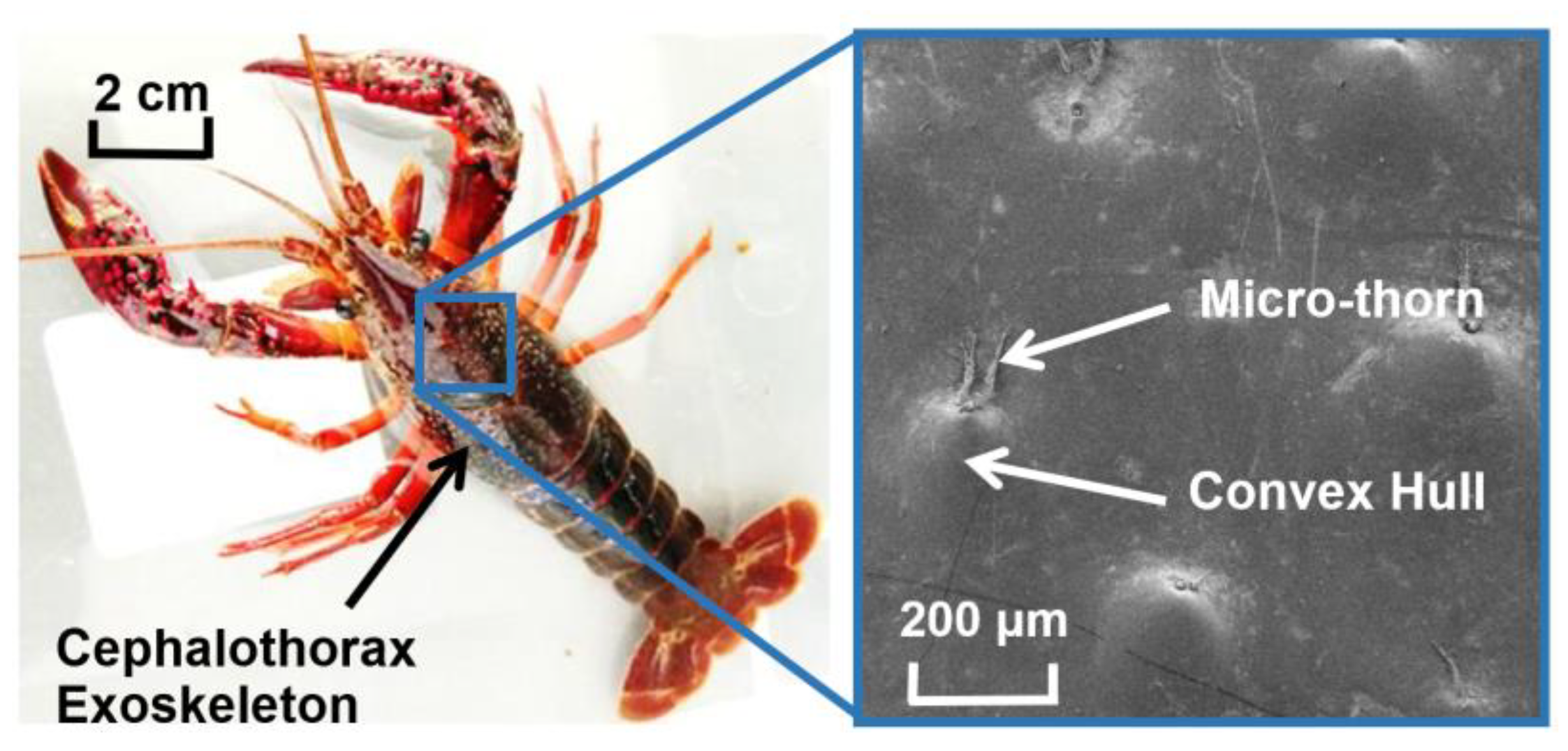
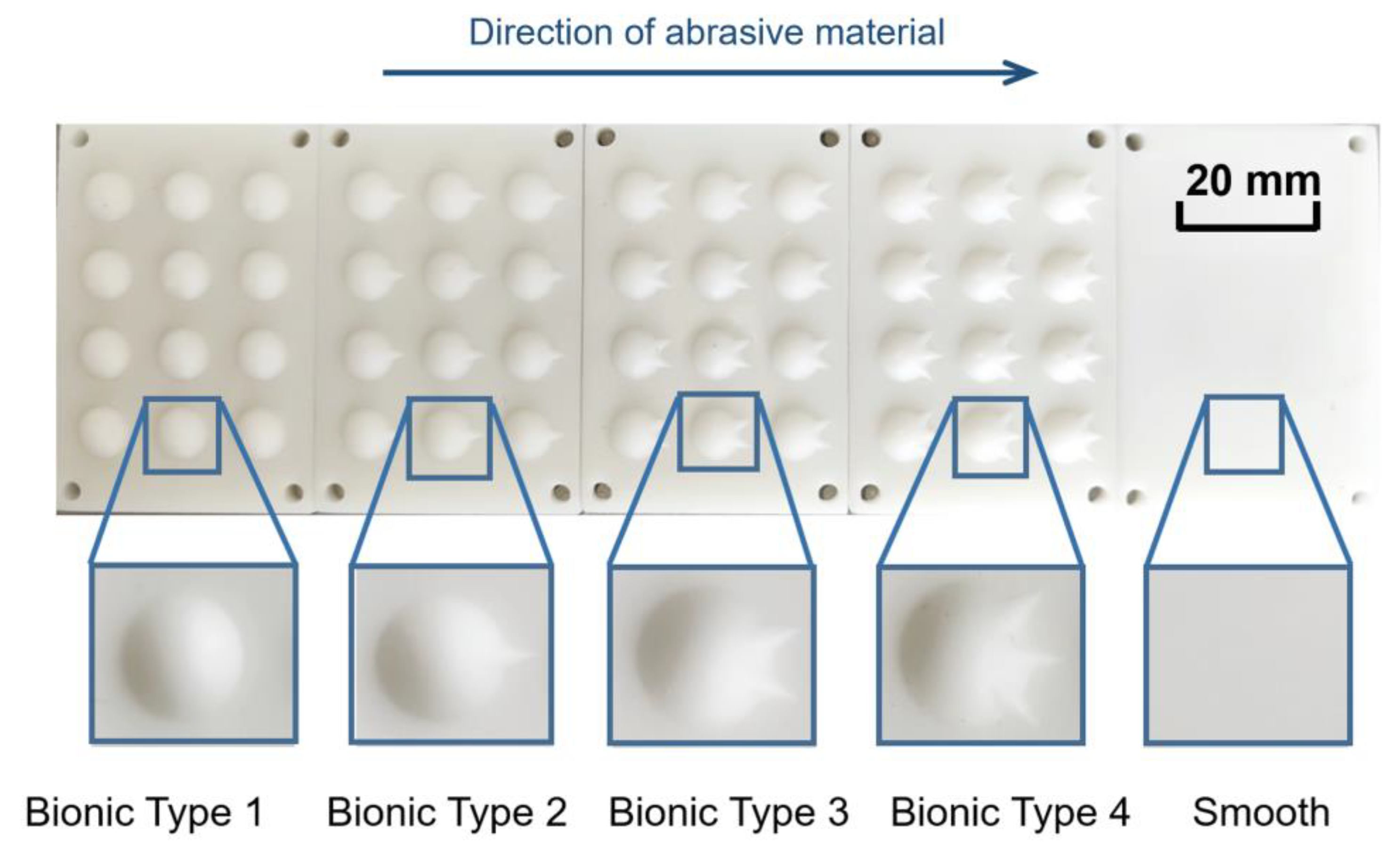
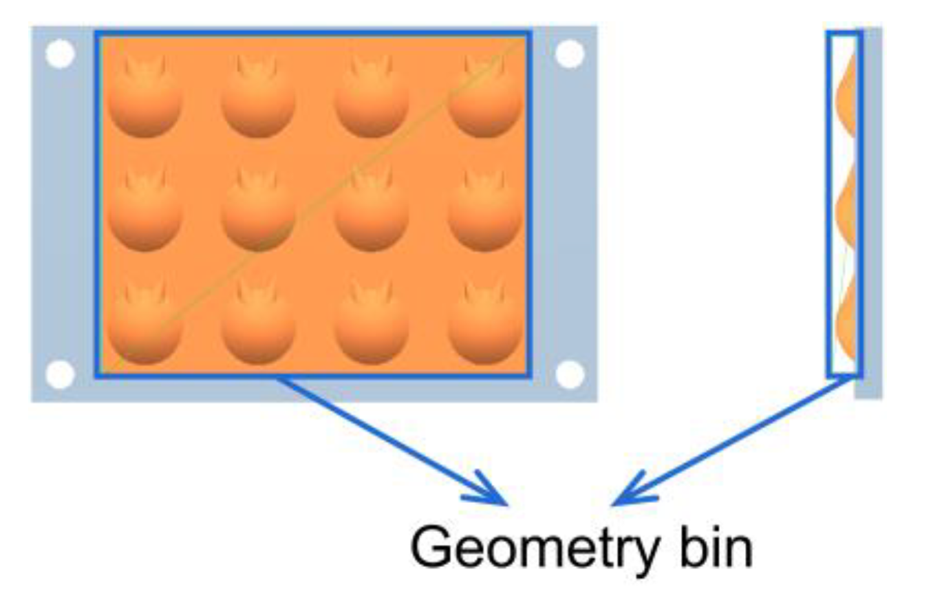
2.1. Bionic Prototype and Geomerical Sturctured Suface Design

The Procambarus clarkii were collected from Chenggong District of Kunming City, Yunnan Province. The mature individuals with body lengths of about 100 mm and dark red body surfaces were selected as the research objects. Field emission scanning electron microscopy (Nova Nano-SEM 450, FEI, Hillsboro, OR, USA) and transmission electron microscopy (JEM-1011, Nippon Electronics, Kitakyushu, Japan) were used to observe the cephalothorax exoskeleton of Procambarus clarkii. It was found that, unlike the ordinary convex hull non-smooth structure commonly seen in the body surface of other soil animals [2], the body surface of Procambarus clarkii presented a special micro-thorn and convex hull coupled structure. Moreover, the number of micro-thorns distributed on the edge of the convex hull was different (Figure 1).
The special surface structure and excellent wear resistance behavior of Procambarus clarkii Cephalothorax exoskeleton provide an excellent natural blueprint prototype for innovative bionic wear resistance surface design. In this study, based on the wear resistance theory of a bionic non-smooth surface [38,39], as shown in Figure 2, three bionic non-smooth geometrically structured surfaces were designed by learning from the micro-thorn and convex hull coupled structured surface on the cephalothorax exoskeleton of Procambarus clarkia. They were bionic single (Bionic Type 2), double (Bionic Type 3) and triple (Bionic Type 4) micro-thorn and convex hull coupled structured surface. To compare the performance of abrasive wear resistance, a convex hull structured surface (Bionic Type 1) and conventional smooth surface without any structures (Smooth) were used as control. The SolidWorks software was used for three-dimensional modeling; a high-precision 3D printer (Wiiboox One, Wiiboox 3D Technology Co., Ltd., Nanjing, China) was used to prepare experimental samples. The sectional dimensions of the samples were 60 × 40 mm, and the height was 4 mm.

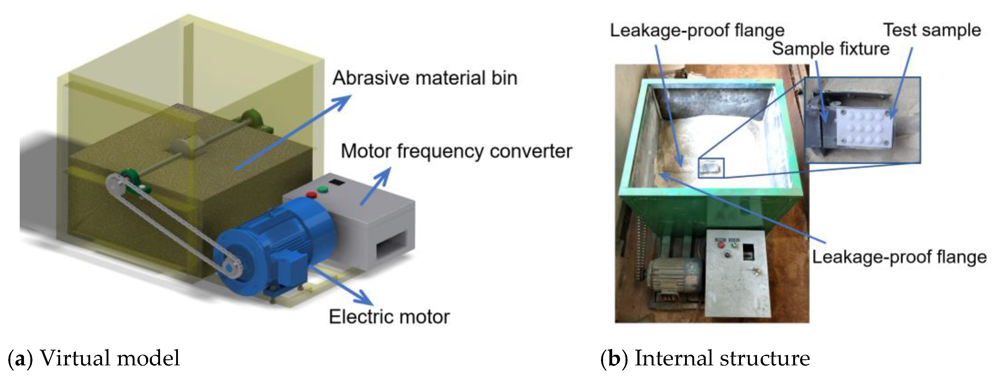
2.2. Abrasive Wear Testing System and Procedure

An abrasive wear testing system was developed to study the anti-abrasive wear performance of test samples. With the purpose of evaluating the abrasive wear resistance performance of soil-engaging components of agricultural machinery, in this study, a rotational abrasive wear testing system that was dedicated to the abrasive wear test of working parts was designed. As shown in Figure 3, the testing system mainly included an electric motor, an abrasive storage box, a sample fixture, a speed control device and a data acquisition device. The motor was a three-phase asynchronous motor, the rated power was 2.2 kw and the rated speed was 2840 r/min. The spindle inside the abrasive material bin was powered by chain drive. The size of the abrasive material bin was 600 × 600 × 600 mm; the spindle had a length of 750 mm, with a diameter of 20 mm, and was located in the center of the material storage box. The sample fixture was installed in the central position of the spindle and rotates with the spindle simultaneously. The test sample fully contacted the abrasive material during the test. Four of the test samples could be installed on the fixture at the same time. Two leakproof flanges were installed inside the contact position between the spindle and the abrasive material bin to prevent the leakage of the abrasive material. The electric motor speed was controlled by the frequency converter and RC41B. The RC41B digital display tachometer was equipped with a Hall sensor. The speed range was ranged between 3.8 and 10,000 r/min, and the error range was ±0.5‰, which met the test requirements.
The particle size of abrasive particles has a certain effect on the wear of the sample surface during abrasive wear. The abrasion loss generally increases with the abrasive particle size [40]. When the abrasive particle reaches a critical size (70 to 100 μm), the abrasive particle size continues to increase and the wear amount tends to be stable [41]. In this study, the mixture of 96.5% quartz sand and 3.5% Bentonite soil was selected as the abrasive of the abrasive wear test. The moisture content of the abrasive was measured by a water sensor, and the moisture content was controlled between 3% and 5% (mass fraction) [42]. The #40 mesh sieve filter screens were used to filter large particles, and #60 mesh sieve filter screens were used to filter small particles, so as to ensure that the abrasive particle size range was between 260 and 420 μm.
The material used to prepare test sample was polylactic acid (PLA). PLA has weak abrasive strength, which aids in speeding up the abrasive wear procedure and shortening the testing time. In addition, PLA has excellent thermal stability [43]. With the increase in friction time, considerable heat could be accumulated, which will raise the temperature of the friction surface of the friction sample. During the test, the temperature of the test sample was checked by an infrared thermometer (GM321, Biaozhi Science and Technology Co., Ltd., Shenzhen, China). It was found that when the test duration was kept within 1 h and the speed of the motor was controlled at 200 r/min, the temperature of the sample surface remained below 50 °C. Therefore, the continuous testing time duration was set at 1 h. After each continuous experiment for 1 h, the motor was stopped. The mass loss of the sample before and after the tests was measured with an electronic balance (Excellence II Excellence, Shanghai Analytic Ping Scientific Instrument Co., Ltd., Shanghai, China). After the test samples were cooled for 0.5 h, the samples were reinstalled to the fixture, the motor was restarted, and the tests continued. The cumulative time of abrasive wear test was 80 h. After the tests were finished, the wear distance was calculated to be 6.09 × 10⁵ m in total. After the abrasive wear test, the wear morphology of the friction specimen surface was observed by a scanning electron microscope (Quanta 200, FEI Company, Hillsboro, OR, USA).

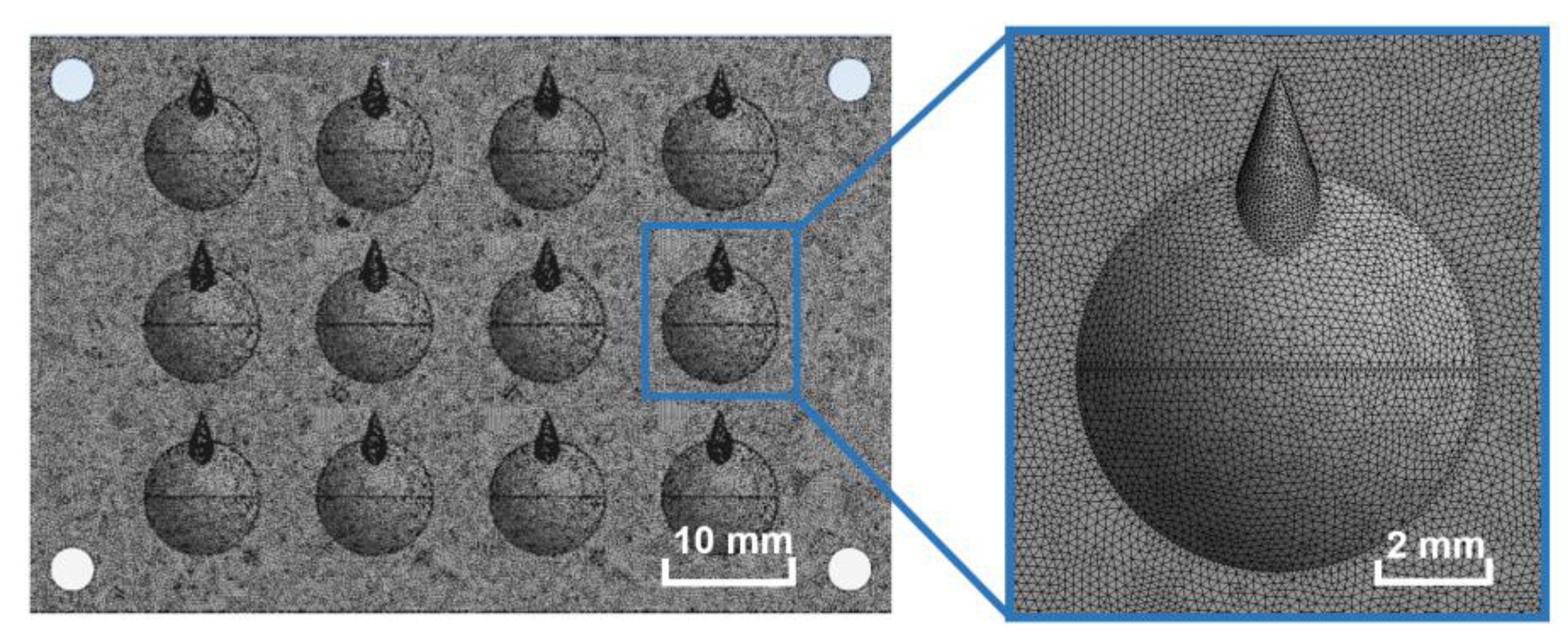
2.3. Settings Material Properties and Contact Parameters in EDEM

The discrete element software EDEM (version 2018, DEM Solutions Ltd., Edinburgh, UK), was used to numerically simulate the abrasive wear process of five different types of surfaces. In order to effectively investigate the wear behavior and morphology of the sample surface in the post-processing of EDEM software, the models need to be meshed. The developed models of the micro-thorn and convex hull coupled structured, convex hull structured and smooth surfaces were transformed into the ‘STP’ file. Then, they were imported into ANSYS Workbench software for meshing operation. The mesh size was 0.1 mm (Figure 4).
To correlate to the abrasive wear test in a real scenario, the quartz sand model was selected as the abrasive particle for the EDEM simulation. As shown in Table 1, the material properties and contact parameters of particles and samples were obtained by referring to the literature and experimental calibration [44,45].

2.4. Settings of EDEM Contact Model and Theoretical Basis

The adequate selection of a contact model is the prerequisite for the effective development of the EDEM discrete element simulation model. The contact between quartz sand particles was set as rigid contact without plastic deformation. The contact between spherical particles and particles will generate normal overlap ξ. The calculation formula is as follows:
ξ = R 1 + R 2 | r 1 r 2 |
where R1 and R2 are the radius of two spherical particles, and r1 and r2 are the center position vectors of two particles.
The normal contact force Fn and the tangential contact force Ft generated by friction will be generated by the contact of two spherical particles, where the calculation formula of Fn is as follows:
F n = S n ξ
where Sn is the normal equivalent stiffness of the particle contact surface, which could be expressed as:
S n = 4 a G 1 v
where G and v are the shear modulus and Poisson’ s ratio of particles, respectively, and a is the radius of the particle contact surface.
The calculation formula could be expressed as follows:
a = 3 π ( 1 V ) 2 n ( 1 ϕ ) R
where n is the number of contact surfaces of a single particle, ϕ is the equivalent porosity of the medium, and R is the local mean curvature radius of the contact surface.
For an ideal spherical particle, the R could be expressed as:
R = R 1 × R 2 R 1 + R 2
Since the tangential contact force Ft is relatively complicated, its size depends on the loading history but is not entirely determined by the relative position of particles. For example, the normal contact force increment ∆Fn and the tangential contact force increment ∆Ft are used to describe the loading history of particles, and the tangential contact force Ft can be calculated by the following equations:
Δ F t = S t Δ ξ ,   S t = 8 a G 1 v
Δ F t = μ f Δ F n
F max S > | Δ F t | = μ f Δ F n
where St is the tangential equivalent stiffness, Δξ is the tangential displacement increment, μf is the friction coefficient, and ΔFSmax is the static friction force.
When the static friction force is greater than the tangential contact force increment, the particles do not cause micro sliding on the contact surface. Therefore, the Hertz–Mindlin no-slip contact model was selected as the contact model between quartz sand particles [46,47].
When quartz sand particles were in contact with the test samples, since a ploughing effect from the abrasive materials existed, the test surfaces were subject to micro shearing, ploughing and cutting. Therefore, grooved grinding marks were generated. In this study, the Hertz–Mindlin with Archard Wear model was selected as the contact model between quartz particles and the surface of the test sample [48].
The general calculative equation could be expressed as:
V = k a W H s
where V is the volume of geometric wear, W is the normal load, s is the friction distance, H is the hardness of the material, ka is the abrasive wear constant which is usually determined by the hardness, shape and the number of abrasive particles for cutting.
The EDEM software simplified the setting of Archard Wear model parameters, which means it only needed to set the value of ka/H. In this study, by referring to investigations by Yuan [49], the value of ka/H was set as 4.4 × 10⁻¹¹.
In the EDEM approach, as presented in Equation (10), to show the wear morphology of the geometry surface, each particle contact unit sets a wear depth d to represent the wear amount of the geometry.
d = V S
where S is the contact area between the geometry and the particle.
Considering the calculation time of the simulation and the size of the geometry grid, the radius of the particles was set to 0.2 mm; the angle between the particle flow and the test surfaces was 30°; the particle velocity was 1 m/s, the number of particles generated per second in the particle factory was 2.0 × 10⁴; and the total number of particles that participated in the calculation was 4.0 × 10⁵.

3. Results and Discussion

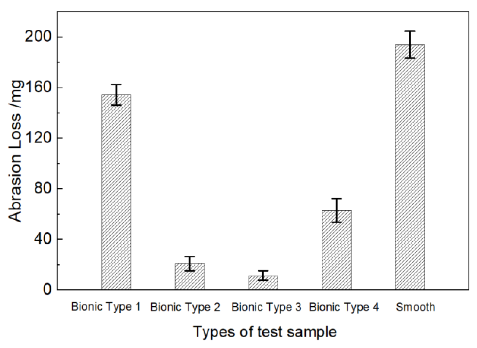
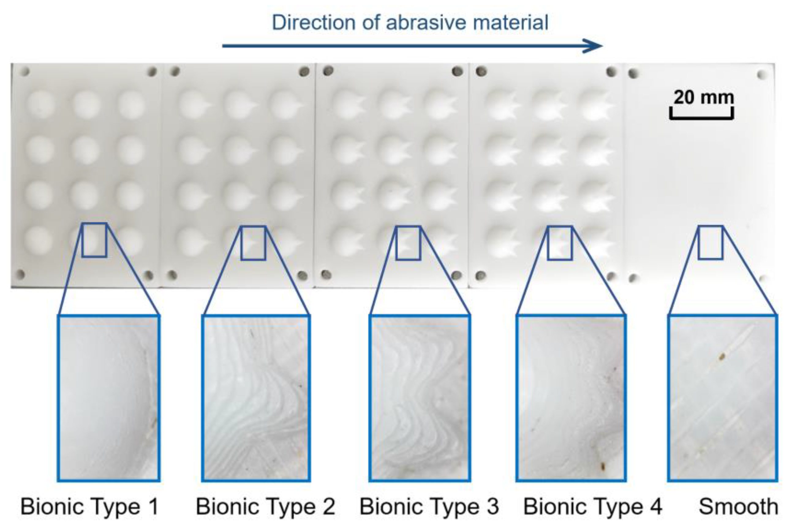
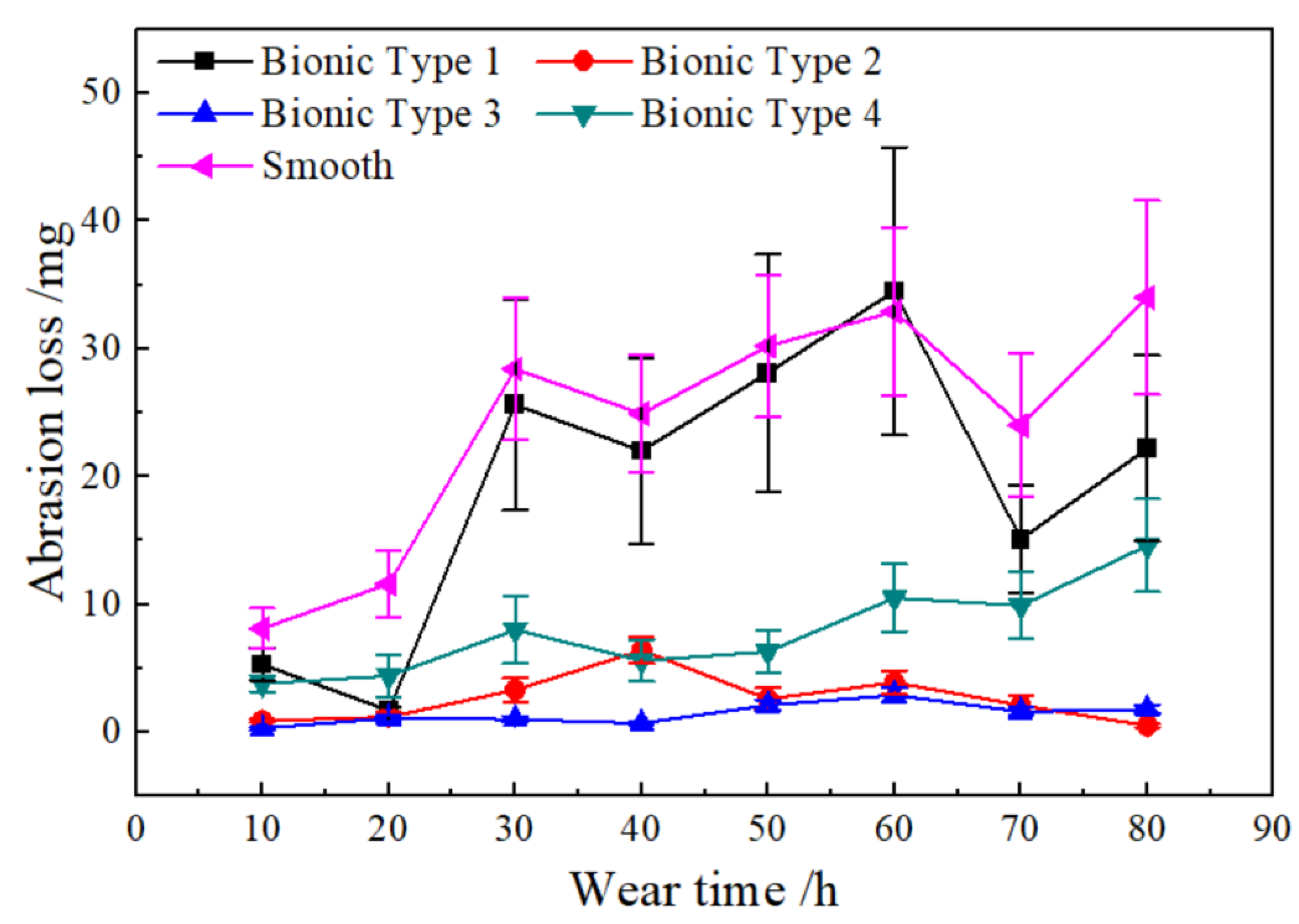
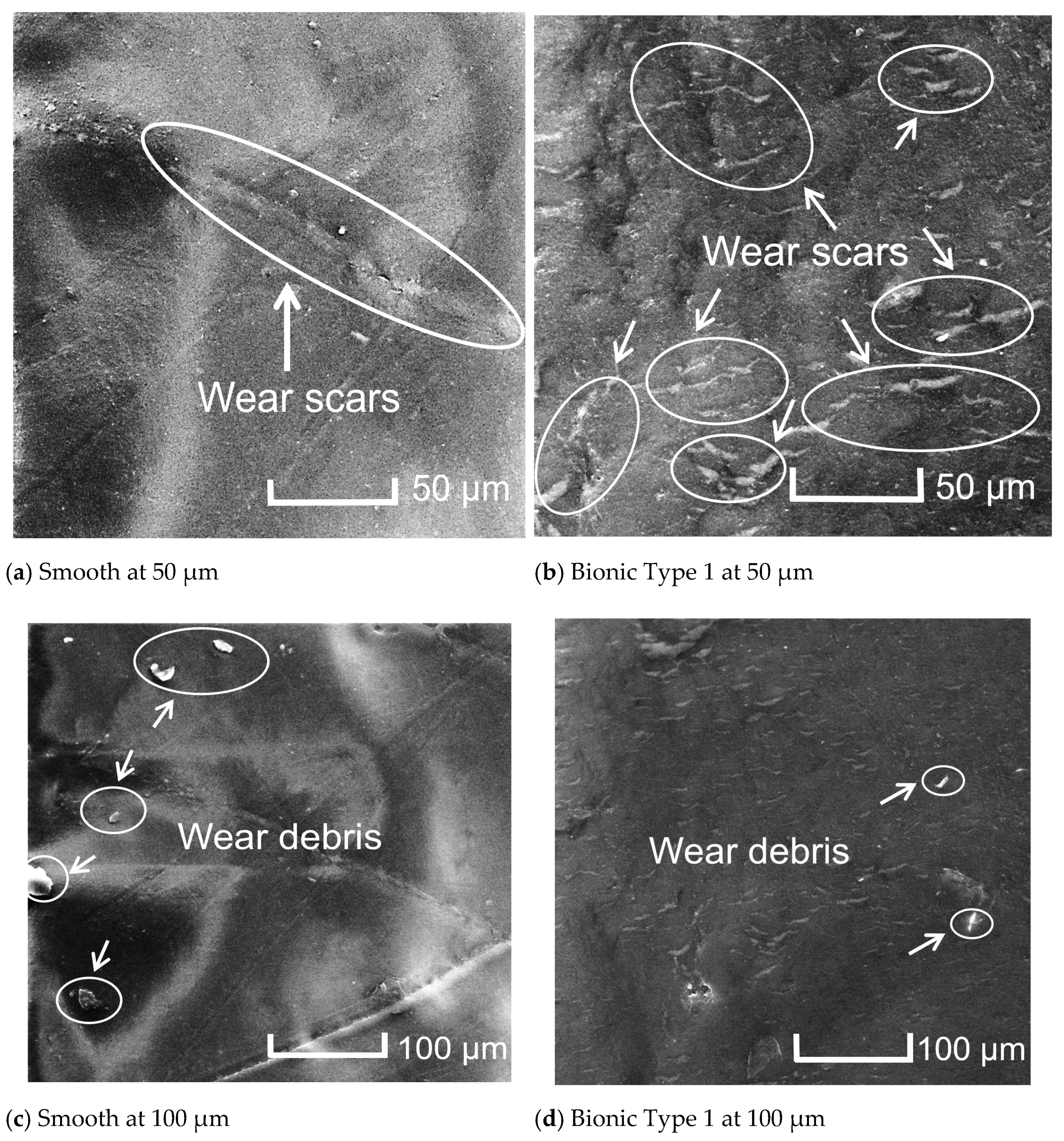
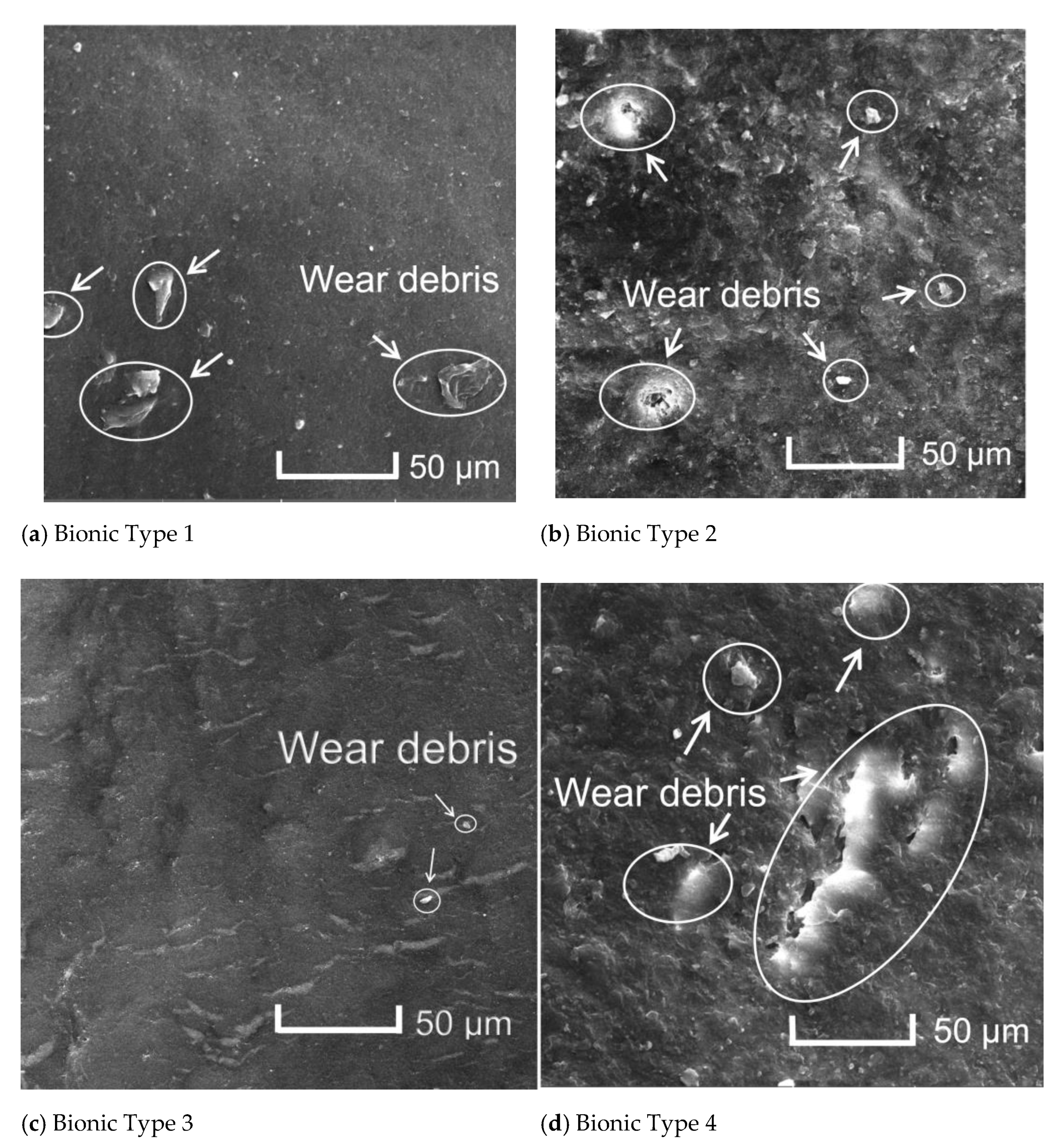
3.1. Abrasion Loss and Worn Surface Micromorphology

Abrasive wear tests were carried out on five types of test samples. As shown in Figure 5, the results showed that there were different severity degrees of abrasive wear on the surface test samples. Among them, the abrasion loss of the conventional smooth surface sample was 194.1 mg. The wear mass of Bionic Type 1 surface sample was 154.5 mg, which was 20.4% lower than that of the smooth surface sample. The abrasion losses of Bionic Type 2, Bionic Type 3 and Bionic Type 4 test samples were 20.9, 11.5 and 63.1 mg, which were 89.2%, 94.1% and 67.5% lower than those of the conventional smooth surface sample, respectively. It was demonstrated that the abrasion losses of all of the bionic non-smooth surface test samples were less than that of conventional smooth surface ones. Among the bionic non-smooth surfaces, the wear resistance performances of micro-thorn and convex hull coupled structured surfaces were substantially further improved as compared to that of the convex hull structured surface without coupled micro-thorn. Among the micro-thorn and convex hull coupled structured surfaces, the Bionic Type 3 had the smallest abrasion loss; therefore, it achieved the best wear resistance performance. To mitigate the problem of the wear failure of soil-engaging components of agricultural machinery, many researchers also applied the bionic approach to the structural surface design to improve component wear resistance. For example, Zhang et al. [50], inspired by the ridged structures on Pangolin squama and Chlamys farreri shell surfaces, demonstrated that that the mass loss of bionic samples was less than that of the flat surface samples. The wear resistance improved, ranging between 33.1% and 77%. Tong et al. [2] learned from the Copris ochus Motschulsky, and designed bio-inspired embossed surfaces consisting of an array of convex domes, and proved the abraded volume reductions ranged between 12.1% and 58.1%. Zhang et al. [24] established an abrasive wear system composed of pangolin scale and abrasive sand based on the discrete element method (DEM), and proved that the geometrical shape of the pangolin scale is helpful for decreasing the boundary stress, especially with the wear rate decreasing when the velocity is higher than a certain degree.
As shown in Figure 6, after 80 h of accumulative test time and the total wear distance of 6.09 × 10⁵ m, the micro-thorns were well preserved. The edges of the micro-thorns were generally neat, even though some fraying was present.
Figure 7 shows that the variation pattern of abrasion loss of five different types of test samples behaved differently. Among all the test samples, the wear rates of the conventional smooth surface and Bionic Type 1 fluctuated greatly with time. Generally, in the first 20 h of wear time, the differences in wear rates of all the test samples were not obvious. However, after 20 h of wear time, the wear rates of the conventional smooth surface and Bionic Type 1 were dramatically increased. Over 80 h of wear time, the wear rates for all of the three micro-thorn and convex hull coupled structured surfaces (Bionic Type1, Bionic Type 2 and Bionic Type 3) were stable and much less than the conventional smooth surface and convex hull structured surface. Among three of the aforementioned test samples, after 50 h of wear time, the wear rates of Bionic Type 2 and Bionic Type 3 slightly decreased with time; however, Bionic Type 4 showed an obviously upward trend.
The worn micro-morphologies of the sample surfaces are shown in Figure 8; it was observed that there were different sized micro grooves and flakes on the surface of test samples, indicating that micro cutting and plastic extrusion peeling occurred during the abrasive wear process. By comparison, it is found that there were obvious wear scars and debris on the surface of the smooth and Bionic Type 1. Although the surface of Bionic Type 1 had more wear scars and debris, the grinding marks were narrow in length, short in length and small in size. However, on the smooth worn surface, the wear scars were thicker, longer and larger as compared with Bionic Type 1. Therefore, the smooth surface suffered much more severe abrasive wear as compared with the Bionic Type 1 surface.
The wear morphology of different bionic geometry surfaces is shown in Figure 9. The convex hull structured surface of Bionic Type 1 showed a higher degree of worn severity. A large volume of debris and wide wear scars (Figure 9a) were distributed. However, as shown in Figure 9b,c, only minor wear scars and debris were observed on the worn surfaces of Bionic Type 2 and Bionic Type 3. Especially for surface of Bionic Type 3, only a mild wear phenomenon was observed. There were coarse wear scars and debris distributed on the wear surface of Bionic Type 4 (Figure 8d). Therefore, among bionic non-smooth surfaces, Bionic Type 3 showed the best anti-abrasive wear performance.

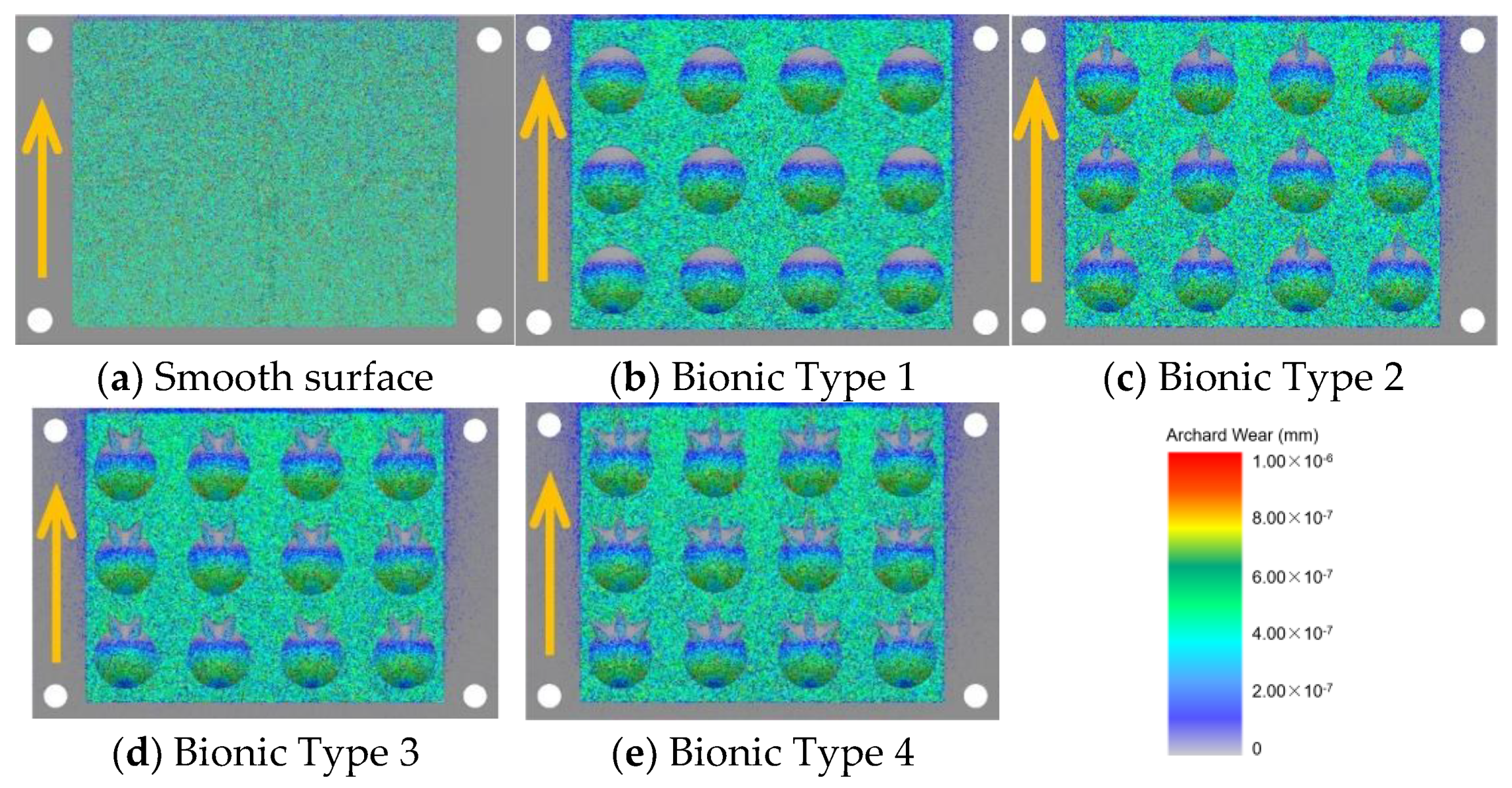
3.2. Analysis of EDEM Simulation Results and Wear Mechanism Investigation

The EDEM approach was used to simulate the interaction between abrasive particles and five different geometric structured surfaces. In the EDEM post-processing module, the “geometry bin” function was used to divide the geometry area (as shown in Figure 10). The particle flow impact area was included in the divided geometry bin. The averaged abraded depth of the divided geometry area was exported. The simulation results are shown in Table 2; it was found that the abraded depth of the conventional smooth surface was the highest, and the average abraded depth reached 1.9766 × 10⁻⁷ mm. The average abraded depth of Bionic Type 1 was 1.7221 × 10⁻⁷ mm, and the wear resistance performance was better than that of the smooth surface, but worse than the micro-thorn and convex hull coupled structured surfaces. Among the micro-thorn and convex hull coupled structured surfaces, Bionic Type 3 showed the lowest abraded depth, which was 1.5656 × 10⁻⁷ mm. It was further proved that among all the test samples, Bionic Type 3 had the best abrasive wear resistance performance. The results obtained from the EDEM simulations generally agreed well with the real scenario experiments.
The worn cloud maps of the five different surfaces are shown in Figure 11. For the conventional smooth surface, the wear severity at different positions of this surface were relatively uniform. For Bionic Type 1 of the convex hull surface without micro-thorn, the worn area was concentrated at the edge of the convex hull that faced the particle flow, while the wear severity of other areas was light. For the micro-thorn and convex hull coupled structured surfaces, the worn area was not only concentrated at the edge of the convex hull that faced the particle flow, but also the micro-thorns that showed a certain degree of signs of wear.
In the process of the abrasive wear test, the abrasive particles had an impact on the sample surface. As a result, a particle–surface contact system was formed. The movement of a single abrasive particle was not only affected by the geometrical structures on the contact surface, but also the surrounding abrasive particles. The wear mechanism of a particle–surface contact system was related to the abrasive particles group and the movement state of each single of abrasive particle. The sliding behavior of abrasive particles played a fundamental role in the wear of the sample surface. The rolling behavior of abrasive particles on the sample surface could substantially mitigate the wear severity of the sample surface [49,51]. The movement of abrasive particles on different types of surfaces is shown in Figure 12. When the abrasive particles were in contact with the smooth surface, the abrasive particles mainly slid on the surface. Therefore, the smooth surface was subjected to high impact force and cutting force. Therefore, the surface wear was more serious. When the abrasive particles were in contact with the bionic Type 1 surface, the edge of the convex hull geometrical structure that faced the particle flow was firstly hit by an incoming flow of particles. Thus, this area was subjected to severe impact force and cutting force, and resulted in being seriously worn. However, the convex hull geometrical structures could alter the contact condition of the abrasive particles in the particle–surface system. By guiding the abrasive particles and changing their direction of motion, the contact behavior altered its form from a sliding to rolling state. Therefore, the wear severity was greatly reduced. Moreover, when the abrasive particles were in contact with the micro-thorn and convex hull coupled structured surfaces, along with the convex hull structure that changes the motion behavior of the particle flow, the guiding and rolling effects were greatly enhanced due to the sharp angle of the micro-thorn structure. The direction of particle movement was further changed by guiding the movement of the abrasive particles to both sides and upwards of the micro-thorn. As a result, abrasive particles that altered from a sliding state to rolling state were substantially increased. Furthermore, the rebound angle of abrasive particles after contact with the sample surface was related to its surface morphology [52,53]. The guiding and rolling effect resulted from the micro-thorn and convex hull coupled structured surfaces were much better than that of the convex hull surface and smooth surface.
After the impact of abrasive particles, the rebound angle and the degree of dispersion of particle flow on Bionic Type 3 were greater than that of Bionic Type 1 and the smooth surface. After the impact on the convex hull structure, part of the particles were rebounded and the rebounded particle flow was formed. The rebounded particle flow was further impacted by the forward incoming particles and then moved backward. In the process of backward movement, they were impacted again by the rebound flow of the previous abrasive particles. In the process of repeated impact, a considerable amount of impact energy was consumed. The repeated impact of abrasive particle flow at different levels could buffer the impact kinetic energy of the incoming frontal impact particles; therefore, the impact and cutting force of the abrasive in contact with the Bionic Type 3 surface were greatly reduced. Therefore, the wear resistance performance of Bionic Type 3 was greatly enhanced.

4. Conclusions

With the purpose of improving the abrasive wear resistance performance of soil-engaging components of agricultural machinery, the micro-thorn and convex hull coupled structured surface that was inspired by the cephalothorax exoskeleton of Procambarus clarkii was selected as the bionic prototype. The technical approach of bionic engineering was adopted; bionic single, double and triple micro-thorn coupled convex hull geometrical structured surfaces (Bionic Type 2, 3, and 4, respectively) were designed and proposed. Taking the abrasive wear performance as the evaluation index, the above-mentioned geometrical structured surfaces were compared with the conventional surface without any structures (smooth) and convex hull structured surface without micro-thorn (Bionic Type 1). The rotary abrasive wear testing system was developed and used in this study to evaluate the wear resistance performance of different types of surfaces. The cumulative test time was 80 h, and the total wear distance was 6.09 × 10⁵ m. Meanwhile, the discrete element method was used to investigate the abrasion mechanism of different types of surfaces. The anti-wear mechanism of bionic non-smooth structured surfaces was investigated. In addition, scanning electron microscopy was used to analyze the wear morphology.
After the end of the test, the abrasion loss of the conventional smooth surface sample reached 194.1 mg. The abrasion loss of the Bionic Type 1 surface sample was 154.5 mg, which is 20.4% lower than that of the smooth surface sample. The abrasion loss of the Bionic Type 2, Bionic Type 3 and Bionic Type 4 test samples were 20.9, 11.5 and 63.1 mg, which were 89.2%, 94.1% and 67.5% lower than those of the conventional smooth surface sample, respectively. It was demonstrated that the abrasion loss of all of the bionic non-smooth surface test samples were less than that of conventional smooth surfaces. Among the bionic non-smooth surfaces, the wear resistance performances of micro-thorn and convex hull coupled structured surfaces were further improved as compared to that of the convex hull structured surface without coupled micro-thorn. Among the micro-thorn and convex hull coupled structured surfaces, Bionic Type 3 showed the smallest abrasion loss; therefore, it achieved the best wear resistance performance.
Scanning electron microscopy (SEM) observation revealed that there were severe wear scars and debris on the smooth surface. The smooth surface suffered much more severe abrasive wear as compared with other surfaces. Among the micro-thorn and convex hull coupled structured surfaces, only minor wear marks and debris were observed. The wear severity for the worn surface of Bionic Type 3 was minimum; hence it showed the best wear resistance performance.
The results obtained by the discrete element method EDEM demonstrated that the abraded depth of the conventional smooth surface was the highest, and the average abraded depth of the geometry bin surface reached 1.9766 × 10⁻⁷ mm. The average abraded depth of Bionic Type 1 was 1.7221 × 10⁻⁷ mm, and the wear resistance performance was better than that of the smooth one, but worse than all of the micro-thorn and convex hull coupled structured surfaces. Among the micro-thorn and convex hull coupled structured surfaces, Bionic Type 3 showed the lowest abraded depth, which was 1.5656 × 10⁻⁷ mm. It was further proved that among all the test samples, Bionic Type 3 had the best abrasive wear resistance performance. Therefore, the results obtained from EDEM simulation are consistent with the real scenario experiments.
The EDEM simulation further revealed that for the conventional smooth surface, the wear phenomena at different areas were relatively uniform. For Bionic Type 1, the worn area was mainly concentrated at the edge of the convex hull that faced the particle flow, while the wear of other areas was less severe. For the micro-thorn and convex hull coupled structured surfaces, the worn area was not only concentrated at the edge of the convex hull that faced the particle flow, but also on the micro-thorns. When the abrasive particles were in contact with the conventional smooth surface, the abrasive particles mainly slid on the surface. The smooth surface was subjected to high impact force and cutting force. Therefore, the surface wear was more serious. The micro-thorn structure facilitated the motion state of contact particles changing from sliding to rolling. The kinetic energy loss of rolling particles on subsequent particle flow is greater than that of sliding particles. The repeated impact of abrasive flow at different levels could buffer the impact kinetic energy of the frontal impact particles; therefore, the impact and cutting force of the abrasive in contact with the micro-thorn and convex hull coupled structured surface were greatly reduced. Moreover, the small rebound angle when the abrasive particles were in contact with the smooth surface has limited influence on the impact kinetic energy of the frontal impact particles, which further indicates that the wear resistance of the bionic micro-thorn and convex hull coupled structured surfaces were better than that of the conventional smooth surface. The research results provide a novel bionic design approach for improving the abrasive wear resistance performance of soil-engaging components of agricultural machinery.

Author Contributions

Conceptualization, Q.Z., J.T. and Z.Z.; methodology, Z.Z.; software, G.Z.; validation, G.Z., Q.L. and Z.Z.; formal analysis, G.Z.; investigation, G.Z.; resources, G.Z.; data curation, G.Z.; writing—original draft preparation, Q.Z.; writing—review and editing, Z.Z.; visualization, G.Z.; supervision, Q.L.; project administration, Q.L.; funding acquisition, Z.Z. All authors have read and agreed to the published version of the manuscript.

Funding

This research was funded by the National Natural Science Foundation of China, grant number 52065031 and 51605210; the National Natural Science Foundation of Huzhou, grant number 2016YZ01; Analysis and Testing Foundation Project of Kunming University of Science and Technology (Nos. 2019T20140038, 2019M20182214012 and 2019M20182214014).

Institutional Review Board Statement

Not applicable.

Informed Consent Statement

Not applicable.

Data Availability Statement

All data included in this study are available upon request by contact with the corresponding author.

Acknowledgments

The authors express their appreciation to Guangming Chen, Guangkai Zhang, Yin Li and Xiaoyang Wang for their technical assistance throughout experiments.

Conflicts of Interest

The authors declare no conflict of interest. The funders had no role in the design of the study; in the collection, analyses, or interpretation of data; in the writing of the manuscript, or in the decision to publish the results.

References

  1. Tong, J.; Mohammad, M.A.; Zhang, J.; Ma, Y.; Rong, B.; Chen, D.; Menon, C. DEM Numerical Simulation of Abrasive Wear Characteristics of a Bioinspired Ridged Surface. J. Bionic Eng. 2010, 7, 175–181. [Google Scholar] [CrossRef]
  2. Tong, J.; Zhang, Z.; Ma, Y.; Chen, D.; Jia, B.; Menon, C. Abrasive wear of embossed surfaces with convex domes. Wear 2012, 274, 196–202. [Google Scholar] [CrossRef]
  3. Khruschov, M.M. Principles of abrasive wear. Wear 1974, 28, 69–88. [Google Scholar] [CrossRef]
  4. Królicka, A.; Szczepański, Ł.; Konat, Ł.; Stawicki, T.; Kostencki, P. The influence of microstructure on abrasive wear micro-mechanisms of the claddings produced by welding used in agricultural soil. Materials 2020, 13, 1920. [Google Scholar] [CrossRef] [PubMed] [Green Version]
  5. Schramm, F.; Kalácska, Á.; Pfeiffer, V.; Sukumaran, J.; De Baets, P.; Frerichs, L. Modelling of abrasive material loss at soil tillage via scratch test with the discrete element method. J. Terramechan. 2020, 91, 275–283. [Google Scholar] [CrossRef]
  6. Horvat, Z.; Filipovic, D.; Kosutic, S.; Emert, R. Reduction of mouldboard plough share wear by a combination technique of hardfacing. Tribol. Int. 2008, 41, 778–782. [Google Scholar] [CrossRef]
  7. Kang, A.S.; Grewal, J.S.; Cheema, G.S. Effect of thermal spray coatings on wear behavior of high tensile steel applicable for tiller blades. Mater. Today Proc. 2017, 4, 95–103. [Google Scholar] [CrossRef]
  8. Frenzel, C.; Käsling, H.; Thuro, K. Factors influencing disc cutter wear. Geomech. Tunn. Geomech. Tunn. 2008, 1, 55–60. [Google Scholar] [CrossRef]
  9. Wang, S.; Li, S.; Zhang, Y.; Wan, Q.; Chen, H.; Meng, L. Mole toe bionics and surface heat treatment improving resistance reduction and abrasion resistance performance of toothed ditching blade. Trans. Chin. Soc. Agric. Eng. 2019, 35, 10–20. [Google Scholar]
  10. Liu, X.; Dong, L.; Yang, J.; Liu, Z.W.; Tao, J.; Wen, Q. Research on the Wear and Protection of Agricultural Implements. In Proceedings of the Computer Science and Engineering Technology (CSET2015) & Medical Science and Biological Engineering (MSBE2015), Hong Kong, China, 30–31 May 2015; pp. 61–66. [Google Scholar]
  11. Wang, J.; He, Q.Z.; Hu, Y.; Wang, M.C. Study on the Microstructure and Performance of New Type Martensite Wear Resistant Steel. Adv. Mater. Res. 2011, 199, 167–172. [Google Scholar] [CrossRef]
  12. Liu, H.; Wang, J.; Shen, B.; Yang, H.; Gao, S.; Huang, S. Influence of secondary carbide precipitation and transformation on abrasion resistance of a 3Cr15Mo1V1. 5 white iron. J. Univ. Sci. Technol. Beijing Miner. Metall. Mater. 2007, 14, 231–235. [Google Scholar]
  13. Wu, Z.; Liu, X. A new heat treatment process for blades of 65Mn steel stubble machine. Trans. Chin. Soc. Agric. Mach. 1994, 1994, 117–119. [Google Scholar]
  14. Li, Q.; Guo, J.; Hu, J. Research status of wear resistance and drag reduction treatment of soil cultivation components. Surf. Technol. 2017, 2017, 126–133. [Google Scholar]
  15. Ren, J.; Jin, S. Friction and wear characteristics of plasma-sprayed Al2O3-40% TiO2 and Cr2O3 coatings on aluminum alloy. Tribol. Int. 2000, 20, 18–21. [Google Scholar]
  16. Foley, A.; Lawton, P.; Barker, A.; McLees, V. The use of alumina ceramic to reduce wear of soil-engaging components. J. Agric. Eng. Res. 1984, 30, 37–46. [Google Scholar] [CrossRef]
  17. Foley, A.; Chisholm, C.; McLees, V. Wear of ceramic-protected agricultural subsoilers. Tribol. Int. 1988, 21, 97–103. [Google Scholar] [CrossRef]
  18. Yang, F.; Chen, X. Application of wear resistant materials in soil tillage components. J. Agric. Mech. Res. 2000, 2000, 111–112. [Google Scholar]
  19. Ren, L.; Liang, Y. Biological couplings: Classification and characteristic rules. Sci. China Ser. E Technol. Sci. 2009, 52, 2791–2800. [Google Scholar] [CrossRef]
  20. Ren, L.; Liang, Y. Biological couplings: Function, characteristics and implementation mode. Sci. China Technol. Sci. 2010, 53, 379–387. [Google Scholar] [CrossRef]
  21. Ren, L.; Liang, Y. Preliminary studies on the basic factors of bionics. Sci. China Technol. Sci. 2014, 57, 520–530. [Google Scholar] [CrossRef]
  22. Tan, L.; Zong, X.; Chang, Z. Design and test of biomimetic wear resistant for et clutch friction plate for heavy tractor. Trans. Chin. Soc. Agric. Eng. 2018, 34, 54–59. [Google Scholar]
  23. Ma, Y.; Lin, F.; Yan, Z. Micro morphology and properties of tribological action for shell in Cyclina sinensis. Trans. Chin. Soc. Agric. Eng. 2013, 29, 298–304. [Google Scholar]
  24. Zhang, R.; Yu, H.; Pang, H.; Chen, G.; Tai, W. Analysis of Wear-Resistant Surface with Pangolin Scale Morphology by DEM Simulation. Appl. Sci. 2020, 10, 2896. [Google Scholar] [CrossRef]
  25. Chen, L.; Zhou, H.; Zhao, Y.; Ren, L.; Li, X. Abrasive particle wear behaviors of several die steels with non-smooth surfaces. J. Mater. Process. Technol. 2007, 190, 211–216. [Google Scholar] [CrossRef]
  26. Zhang, J.; Tong, J.; Ma, Y. Abrasive wear characteristics of subsoiler tines with bionic rib structure surface. J. Jilin Univ. Eng. Technol. Ed. 2015, 45, 174–180. [Google Scholar]
  27. Hu, L.; Hu, G. Techniques and implementation of granular DEM simulation for mechanical product design. J. Mech. Eng. 2015, 51, 59–69. [Google Scholar]
  28. Rong, B. Biomimetic Geometrical Structure Surfaces with Anti-Abrasion Function and Their Abrasive Wear Against Soil; Jilin University: Changchun, China, 2008. [Google Scholar]
  29. Li, F.; Fu, K.; Yu, X. Optimization of grinding performance for large-type semi-autogenous mill based on analytic hierarchy process. Trans. Chin. Soc. Agric. Mach. 2017, 48, 392–398. [Google Scholar]
  30. Kalala, J.; Bwalya, M.; Moys, M. Discrete element method (DEM) modelling of evolving mill liner profiles due to wear. Part II. Industrial case study. Miner. Eng. 2005, 18, 1392–1397. [Google Scholar] [CrossRef]
  31. Franke, J.; Cleary, P.W.; Sinnott, M.D. How to account for operating condition variability when predicting liner operating life with DEM–A case study. Miner. Eng. 2015, 73, 53–68. [Google Scholar] [CrossRef]
  32. Chen, G.; Lodewijks, G.; Schott, D.L. Numerical prediction on abrasive wear reduction of bulk solids handling equipment using bionic design. Part. Sci. Technol. 2019, 37. [Google Scholar] [CrossRef]
  33. Chen, G.; Schott, D.L.; Lodewijks, G. Bionic design methodology for wear reduction of bulk solids handling equipment. Part. Sci. Technol. 2017, 35, 525–532. [Google Scholar] [CrossRef]
  34. Chen, G. DEM Simulation in Wear Behaviors of Bionic Structures Based on Four Wear-Resistant Biological Surface Morphologies; Jilin University: Changchun, China, 2012. [Google Scholar]
  35. Zhang, Z.; Zhang, G.; Tong, J.; Lai, Q.; Gao, X.; Tang, Y.; Carr, S. Microstructure and tribology characteristics of head and chest exoskeleton of Procambarusclarkii. Trans. Chin. Soc. Agric. Eng. 2018, 34, 52–58. [Google Scholar]
  36. Zhang, S.; Zhang, J.; Zhu, B.; Niu, S.; Han, Z.; Ren, L. Progress in bio-inspired anti-solid particle erosion materials: Learning from nature but going beyond nature. Chin. J. Mech. Eng. 2020, 33, 1–27. [Google Scholar] [CrossRef]
  37. Gong, S.; Li, L.; Lu, J. A study on burrowing behavior of Procambarus clarkii. Freshw. Fish. 2007, 37, 3–7. [Google Scholar]
  38. Chirende, B.; Li, J.; Wen, L.; Simalenga, T.E. Effects of bionic non-smooth surface on reducing soil resistance to disc ploughing. Sci. China Technol. Sci. 2010, 53, 2960–2965. [Google Scholar] [CrossRef]
  39. Wang, Z.; Wang, Z.; Chunxiang, Z. Experiment research on wear mechanism with bionic non-smoothed surface. Mater. Sci. Technol. 2006, 14, 275–278. [Google Scholar]
  40. Thakare, M.; Wharton, J.; Wood, R.; Menger, C. Effect of abrasive particle size and the influence of microstructure on the wear mechanisms in wear-resistant materials. Wear 2012, 276, 16–28. [Google Scholar] [CrossRef]
  41. Zhou, P. Effect of soil abrasive properties on wear performance of agricultural machinery materials. Trans. Chin. Soc. Agric. Mach. 1986, 1986, 55–64. [Google Scholar]
  42. Tong, J.; Ren, L.; Chen, B. Fractal dimension of soil particle-size distribution and their effects on soil adhesion behaviour. Trans. Chin. Soc. Agric. Eng. 1994, 1994, 27–33. [Google Scholar]
  43. Zhang, L.; Zhang, W.; Cai, G. Study on the thermal property parameters of PLA. China Plast. Ind. 2012, 40, 68–71. [Google Scholar]
  44. Van Name, F., Jr. Experiment for Measuring the Coefficient of Restitution. Am. J. Phys. 1958, 26, 386–388. [Google Scholar] [CrossRef]
  45. Zhang, G.; Xiang, X.; Tang, H. FieldI test and numerical calculation of restitution coefficient of rockfall collision. Chin. J. Rock Mech. Eng. 2011, 30, 1266–1273. [Google Scholar]
  46. Archard, J. Contact and rubbing of flat surfaces. J. Appl. Phys. 1953, 24, 981–988. [Google Scholar] [CrossRef]
  47. Van Liedekerke, P.; Tijskens, E.; Dintwa, E.; Rioual, F.; Vangeyte, J.; Ramon, H. DEM simulations of the particle flow on a centrifugal fertilizer spreader. Powder Technol. 2009, 190, 348–360. [Google Scholar] [CrossRef]
  48. Kim, J.-W.; Jung, S.; Kim, J.; Kim, J.; Seo, T. Optimal design of the front linkage of a hydraulic excavator for multi-objective function. J. Mech. Sci. Technol. 2014, 28, 3103–3111. [Google Scholar] [CrossRef]
  49. Yuan, C. Study of Surface Characteristics Both of Wear Particles & Wear Components and Their Relationship in Wear Process; Wuhan University of Technology: Wuhan, China, 2005. [Google Scholar]
  50. Zhang, J.; Zhang, Q.; Ge, Y.; Jiang, Y. Analysis of the Wear-Resistance Characteristics of Bionic Ridge Structures. Appl. Eng. Agric. 2020, 36, 697–702. [Google Scholar] [CrossRef]
  51. Bhushan, B. Introduction to Tribology; John Wiley & Sons: Hoboken, NJ, USA, 2013. [Google Scholar]
  52. Tong, J.; Lü, T.-B.; Ma, Y.-H.; Wang, H.-K.; Ren, L.-Q.; Arnell, R. Two-body abrasive wear of the surfaces of pangolin scales. J. Bionic Eng. 2007, 4, 77–84. [Google Scholar] [CrossRef]
  53. Tong, J.; Wang, H.; Ma, Y.; Ren, L. Two-body abrasive wear of the outside shell surfaces of mollusc Lamprotula fibrosa Heude, Rapana venosa Valenciennes and Dosinia anus Philippi. Tribol. Lett. 2005, 19, 331–338. [Google Scholar] [CrossRef]
Figure 1. Microstructure of Cephalothorax exoskeleton of the Procambarus clarkii.
Applsci 11 06655 g001
Figure 2. Five types of abrasive wear experimental sample (the direction of abrasive material is from left to right).
Applsci 11 06655 g002
Figure 3. Abrasive wear testing system.
Applsci 11 06655 g003
Figure 4. Mesh generation of geometrical model.
Applsci 11 06655 g004
Figure 5. Abrasion loss of 5 types of test sample.
Applsci 11 06655 g005
Figure 6. Wear surfaces in macroscopic scale of five types of abrasive wear experimental samples (the direction of abrasive material is from left to right).
Applsci 11 06655 g006
Figure 7. Temporal evolution of wear rates.
Applsci 11 06655 g007
Figure 8. Worn micromorphology of different test samples.
Applsci 11 06655 g008
Figure 9. Surface wear patterns of different bionic geometrically structured surfaces.
Applsci 11 06655 g009
Figure 10. Geometry bin for analysis divided from geometry region.
Applsci 11 06655 g010
Figure 11. Cloud map of worn surface morphology (the direction of abrasive movement is indicated by the arrow).
Applsci 11 06655 g011
Figure 12. Interaction between abrasive particles and different types of surfaces by EDEM numerical simulation.
Applsci 11 06655 g012
Table 1. Material properties and contact parameters.
TypeParameterValue
Quartz sandShear modulus/GPa0.2
Poisson’s ratio0.25
Density/kg·m−32350
PLAShear modulus/GPa1.4
Poisson’s ratio0.35
Density/kg·m−31248
Contact between quartz sand particlesCoefficient of restitution0.3
Static friction factor0.5
Rolling friction factor0.01
Contacts between quartz sand and PLACoefficient of restitution0.2
Static friction factor0.5
Rolling friction factor0.01
Table 2. Averaged abraded depth.
Type of SamplesBionic Type 1Bionic Type 2Bionic Type 3Bionic Type 4Smooth
Averaged wear depth/10−7 mm1.72211.57411.56561.62931.9766
Publisher’s Note: MDPI stays neutral with regard to jurisdictional claims in published maps and institutional affiliations.

