Article

Experimental Characterization of the Capacitively Coupled RF-Plasma Thruster

Institute for Plasma Technology and Basics of Electrical Engineering, Bundeswehr University Munich, Werner-Heisenberg-Weg 39, 85579 Neubiberg, Germany
*
Author to whom correspondence should be addressed.
Appl. Sci. 2021, 11(15), 6799; https://doi.org/10.3390/app11156799
Submission received: 29 June 2021 / Revised: 19 July 2021 / Accepted: 20 July 2021 / Published: 23 July 2021
(This article belongs to the Special Issue Plasmas for Space Propulsion)

Abstract

:
A novel design of a neutralizer-free plasma thruster is proposed. This setup features a capacitively coupled RF discharge for plasma generation combined with a magnetic nozzle configuration for acceleration. Characteristics of the plasma plume and ions flux are investigated with the help of emissive probes and retarding potential analyzers (RPA). Essential parameters of the thruster like ions energy, ions flux, utilization efficiencies, and thrust are estimated. The investigated system produces a beam of ions accelerated to an energy of 10 eV when operated at power levels of ~20 W and a mass flow of 1.2 mg/s. The ion energy coincides with the potential drop in the plasma plume indicating that the acceleration takes place due the formation of an ambipolar electric field in the expanding plasma. The design is compared to the data available of other similar thrusters.

1. Introduction

In-space electric propulsion is becoming a more and more popular instrument for spacecraft orbit correction, orbit sustaining, and even larger ΔV maneuvers. While standard types of thrusters, such as Hall Effect thrusters, gridded ion thrusters, and arcjets are constantly improving and are already being used in various space missions, space agencies are interested in disruptive technologies for electric propulsion as well. Recent successes in the development of neutralizer-free electric propulsion technologies, for example the electron cyclotron resonance thrusters (MINOTOR [1,2], AQUAJET [3]), show the potential of ion acceleration in expanding plasmas. The acceleration is supposed to take place in the electric field formed in the plasma plume. The formation of this field is attributed to an ambipolar field created by plasma expansion [4,5].
Two possible mechanisms of RF power coupling to a plasma exist. The inductive (ICP) and capacitive (CCP) coupling result in different plasma properties. While the ICP delivers higher plasma densities, the CCP has the benefit of easier plasma ignition. In certain configuration the so called self-biasing effect in CCP plasmas takes place when one of the electrodes gets charged to several hundred volts relative to the plasma. This creates an ion flux of the same energy to this electrode and is usually employed for ion bombardment purposes in plasma etching devices. It is also possible to use this effect in electric propulsion, for example as described in [6] where a combination of ICP and CCP plasmas is used. In CCP plasmas two types of heating mechanisms for electrons exist—collisionless and ohmic heating [7,8,9] the former dominating at lower and latter at higher gas pressures. The transition between these two modes of energy transfer is also accompanied by an increase in the role of secondary electrons in the sustainment of the discharge [7,8,9]. These electrons which are created by the ion bombardment of the electrode surface are called γ-electrons. The corresponding transition is sometimes called the transition between α and γ modes of a CCP discharge with the γ mode being characterized by an increased value of electron density [9]. It appears that the investigated design is also affected by this mode change.
The presented paper investigates the new thruster C-STAR based on the CCP mode of an RF discharge operating at small powers of ~20 W and moderate mass flows. According to the results of the first measurements this thruster is able to create ion beams accelerated to energies of 10 eV.

2. Materials and Methods

2.1. Thruster Description

C-STAR is a capacitively coupled radiofrequency plasma thruster, employing a magnetic nozzle. The principal design, a view of the plasma plume and an estimation of the magnetic field profile is given in Figure 1. The construction is rather simple. It consists of an inner rod electrode (1), an outer ring electrode (2), an insulator, acting also as propellant dispenser (3), and a magnet system (4). Rod magnets are installed inside the central electrode, and ring magnets are mounted onto the outer side of the grounded ring electrode (s. Figure 1a). For preliminary tests permanent magnets are used, but those will most likely be exchanged for electric magnets in the future. The gas dispenser is designed to deliver a uniform gas distribution inside of discharge channel. It also guides the propellant along the electrode walls, delivering additional convectional cooling.
The RF power is applied through a matching unit to the inner electrode. The outer electrode is connected to the grounded thruster housing. The plasma is generated inside the ring channel between two electrodes. Neutral propellant leaves the thruster due to thermal expansion and pressure gradients. The electrons are fully magnetized with the present configuration of the magnetic field. The Larmor radius for electrons with an energy of 5 eV ranges from 0.05 mm inside the discharge channel (160 mT) to 1 mm at the far edge of plasma plume (3 mT). The electrons follow the magnetic field lines and create an ambipolar electric field (sometimes called the electric double layer) which in turn contributes to the acceleration of ions.

2.2. Experimental Setup

In order to evaluate the performance of the C-Star the exhaust plume was investigated using probes as well as a retarded potential analyzer. In all tests argon was used as main propellant.

2.2.1. RF Generator

For powering the thruster an in-house made radiofrequency generator based on the electron valve SRS4453 was used. The generator was operated at constant power delivering 20 W to the thruster. The ignition threshold for the discharge was 7 W. The generator was able to perform a frequency self-adjustment within a certain range. All tests were conducted at approximately 80 MHz of oscillation frequency. To match the radiofrequency generator to the load, an MFJ-989D load tuner was used. Both the RF generator and the matching network were installed outside the vacuum chamber. The overall electrical scheme of thruster connection is depicted in Figure 2.
Power transmitted to the thruster was measured by a power meter built into the matching network, and crosschecked by Rogowski coil current measurements as well as direct voltage measurements at the thruster input. Similar power levels should be provided by a flight-ready device (RFG) as well, but such a device does currently not exist for a CCP and needs to be carefully designed.
Typically, current flight-ready radiofrequency generators generate power-matching to the plasma of a thruster by adjusting the frequency. Unfortunately, most of them are designed for inductively coupled discharge, and have embedded capacities to “prematch” it to the thruster it was built for. That means, that in our case of a capacitive thruster, a proper RFG would require additional inductances but those are also a source of heat losses, and their installation close to the RFG on the spacecraft could lead to overheating of crucial components. Hence more work is needed in this field to enable the C-STAR to become a space-qualified device.

2.2.2. Vacuum Facility

“Morthymer” is a vacuum facility of EIT1, Bundeswehr University Munich. It is a vacuum chamber with a volume of 0.1 m3 and about 0.5 m in diameter. A general view is presented in Figure 3.
The chamber is equipped with a fore-vacuum pump, with an oil adsorption trap on the inlet, one turbomolecular pump, and a small, efficient ion getter pump. The pumping speed of the system is up to 660 l/s, which provides a dynamic vacuum at the level of 5 × 10⁻⁶ mbar at a flow rate of up to 5 sccm. Its construction allows to easily access all devices installed in the facility, and to quickly obtain an oil-free vacuum inside the vacuum chamber, which is a perfect solution for short tests requiring frequent minor changes of the experimental setup during test campaign.
One of the main features of this facility is the moving platform in the lower section of the vacuum chamber. It consists of a linear stage mounted on a rotary vacuum feedthrough. Both moving mechanisms are equipped with stepper motors, allowing to move the platform in radial and azimuthal direction. This enables a limited 2D scan inside the vacuum chamber on the horizontal plane. The accessible regions for the measurements, with the thruster mounted horizontally are shown in Figure 4b. A general view is presented on Figure 4a. The center of the rotation stage was offset by 90 mm from the cut-off (i.e., the front face) of the engine. The measurement domains are indicated in Figure 4. The measurements were conducted along the line of the linear stage in different rotational positions. Typical steps of 30 mm along the line and 15 degrees between rotations were chosen.

2.3. Diagnostics

The plasma diagnostics was focused on determining the electric potential distribution inside the plasma plume and the ion energy distribution function. For this purpose, custom-made emissive probes and a retarding potential analyzer were used. An emissive probe is made of a tungsten wire heated to a temperature such that thermionic emission of electrons takes place. It is usually applied for the measurements of plasma potential [10,11]. When the heating is turned off it can be used as an ordinary Langmuir probe, provided the necessary conditions of Langmuir probe theory are satisfied. By comparison of the probe characteristics taken in hot and cold states it is possible to estimate plasma density as shown later.

2.3.1. Emissive Probes

The emissive probe design is shown in Figure 5. The probe tip is made of a tungsten wire with a diameter of 0.025 mm. The tungsten wire was fused into the glass capillary tubes. The other end of these tubes was connected onto the copper contact wires. The whole assembly was placed into a long Al2O3 tube holder. The length of the wire exposed to the plasma is approximately 2 mm. The typical value of the electron current collected by the cold emissive probe varies between 1 and 50 microamperes. The probe has two electrical contacts for connecting the heating power supply. The needed values of heating current lie in the region of 200–250 mA at voltages between 1 and 2 volts, which corresponds to a heating power of 0.2–0.5 Watts.
An electrical scheme of the emissive probe measurements is depicted in Figure 6. A DC power supply Voltcraft VSP 1410 was used to deliver the heating power to the emissive probes. A Keithley 2410 source measure unit (SMU) connected to a PC was used for the measurements. The voltage–current characteristics of the probe were measured. It can be shown [10] that the plasma potential lies within 1.5 Te from the value of the floating potential of the emitting probe. The electron saturation current was used for the estimation of the electron density. Two kinds of measurements were performed. One is the so called “full” measurement, where the complete VCC of the probe was collected in each step. During the “quick” measurements only the floating potential of the hot probe was measured. The first type of the measurement allowed for the estimation of both the plasma potential and the electron density, the second type delivered only plasma potential information, but was performed with higher resolution.
To illustrate the working principle of the emitting probe the voltage–current characteristics are shown in Figure 7a. The measurements at two different spatial positions with two different emission currents are presented.
The electrons emitted by a hot probe are able to leave the probe only if the probe is biased negatively relative to the plasma potential. As long as the probe is more positive than the plasma potential the thermionic electrons do not contribute to the probe current. Thus in this range the probe is working like a Langmuir probe in collecting mode and the VCC of the hot probe should coincide with that of the cold probe. When scanning the probe voltage the transition through the plasma potential value is marked by the sudden change of the probe current by the value of the thermionic current. Therefore the emissive probes are well suited for the determination of plasma potential.
The transition from the collecting mode (probe is positive) to the emitting mode (probe is negative) is marked by the sign reversal of the probe current. It can be shown, that in the limit of the large emission current the floating potential of the emissive probe approaches the value of the plasma potential [11]. The floating potential is by definition the potential at current zero hence the value of the probe potential at zero current yields the value of the plasma potential. This can be easily measured by the SMU working in current source mode with a zero set value. The data in Figure 7a illustrate the potential difference of 6 volts between positions 70 mm and 190 mm away from thruster cut off.
The parts of the VCC for the collecting mode (positive probe) should be independent from the heating power. This is confirmed by the curves in Figure 7a where the curves at different heating powers coincide in the range above plasma potential.
In addition, the stability of the data is confirmed by the overlapping parts of the VCCs above the plasma potential. The measurements with two different emission currents were taken with one hour delay to each other. The good agreement of the curves justifies the stability of the RF discharge.
For the estimation of the electron density the VCCs of the cold emissive probe, working in Langmuir probe regime, were compared to those of the hot probe for a limited amount of points, see example in Figure 7b. As was mentioned earlier the part of the emissive probe’s VCC above the plasma potential should be equal to that of a cold Langmuir probe. Data in Figure 7b indicate that the hot probe delivers approx. Values of the electron saturation current 20–50% are higher than the cold (Langmuir) probe. Taking into account that the applicability of the Langmuir probe methods are limited in our case, only the estimation of the electron density can be obtained. The reasons are the presence of a magnetic field, a deviation of the probe form the cylindrical shape and space charge effects of the emitting probe. Nevertheless taking the hot probe’s current at the voltage Vpl + 4 V we obtain an acceptable approximation for the electron saturation current I0 of a Langmuir probe.
For a Langmuir probe the value of the electron current I0 at the plasma potential is proportional to the density of the electrons n. The latter can be calculated if the temperature of electrons Te and the surface area S of the probe are known:
n = I0/(evS),
where v = sqrt(8eTe/(meπ)) is the thermal electron velocity, e is elementary charge and me is electron mass. For the estimation of electron density, the temperature of the electrons remains the only unknown parameter. Its influence can be checked by comparing the values of electron density calculated with Te values of 2 and 10 eV (which is the maximal possible range of expected electron temperatures in our case). Using the values of I0 at 70 mm from the front of engine in Figure 7b, results in an electron density estimation between 1.1 × 10¹⁴ and 2.5 × 10¹⁴ m−3 for the values of the electron temperatures of 10 eV and 2 eV respectively. Given the limited applicability of Langmuir probe technique an average value of 1.8 ± 0.7∙1014 m−3 can be adopted.

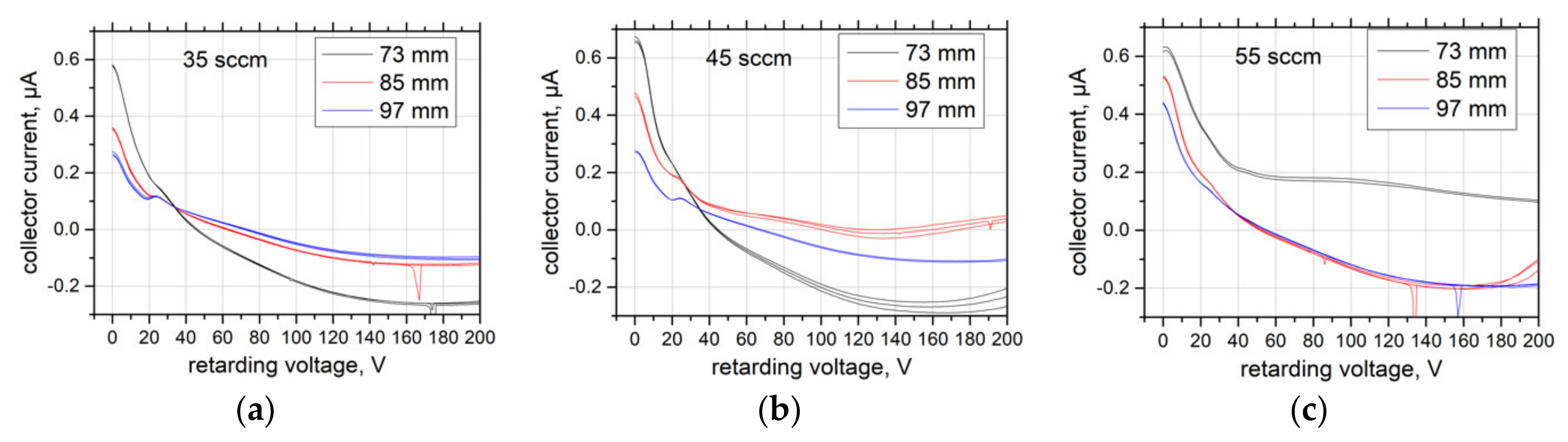
2.3.2. Retarding Potential Analyzer
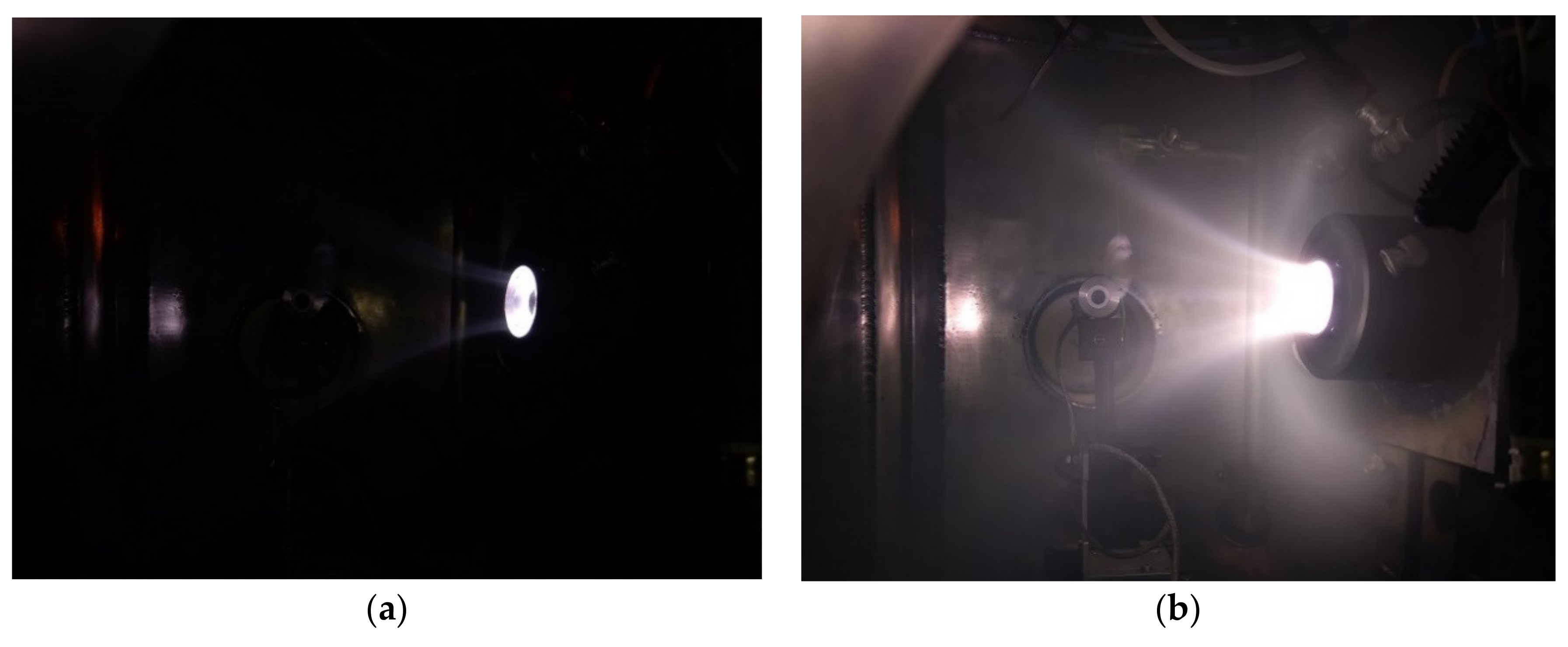
Another diagnostic tool used in this research is a Retarding Potential Analyzer (Figure 8), which uses a series of electrostatic grids to selectively repel the constituents of a plasma and a conductor in order to detect the ion energy distribution. It was also placed inside the vacuum facility on a 2D manipulator, allowing to scan ion energies with the RPA inside the plasma beam.
The electrical scheme of the retarding potential analyzer measurements is depicted in Figure 9. A DC power supply Voltcraft VSP 1410 was used as voltage source for the second grid, repelling electrons. A Keithley 2410 SMU connected to the PC was generating the scanning voltage for the third grid, repelling ions. A Keithley 2450 was measuring the current on the ion collector on the bottom of retarding potential analyzer.

3. Results

The plasma plume at three mass flows of the propellant was investigated. The vacuum facility was sustaining relatively low pressures during the tests of 5 × 10⁻⁵ mbar—1 × 10⁻⁴ mbar. Vacuum properties could noticeably affect parameters of such type of thrusters, according [2], but the gathered plasma parameters are still useful for a basic understanding of the thruster operating principle. The measurement domain shown in Figure 4 delivers data for two sectors located on opposite directions relative to the rotation axis. The example of the raw measured data for a propellant flow of 35 sccm is shown in Figure 10a. To obtain a better impression of the results those were symmetrized relative to the axis of the thruster, as shown in Figure 10b. The results for different propellants flows are compared in Figure 11.
A similar representation of the electron density data is given in Figure 12. The scales for diagrams in this figure are the same except for results obtained at a flow of 35 sccm, where the scale is changed by approx. an order of magnitude due to smaller absolute values of the electron density.
The RPA data are shown in Figure 13. Measurements at three different positions: 73, 85, and 97 mm away from the front of the thruster were conducted. Each measurement was repeated three times to evaluate the accuracy. The corresponding ion energy distribution functions (IEDF) are given in Figure 14.

4. Discussion

The measurements of the plasma potential prove the existence of the electric field in the plasma plume which accelerates ions and decelerates electrons. This is the typical behavior for the ambipolar fields in the plasma. The axial profiles of the plasma potential for three investigated mass flows are shown in Figure 15. There exists a difference in the potential of approximately 10–15 V between the front of the engine and more the distant regions. The decrease of the potential in front of the cut-off seem to be an artefact of the symmetrization procedure. When measured in “quick” 1D mode with higher resolution the potential profile does not show such a behavior (opened circles in Figure 15). Also, a small potential well of the order 1V can be seen between 80 and 100 mmm away from the engine front. There is a jump in the absolute value of the potential between flows 35 and 45, 55 sccm. This just can be correlated to the transition between α and γ modes of the CCP discharge. This transition is also illustrated by the overall appearance of the discharge in Figure 16.
The IEDF in Figure 14 shows the presence of a low energy peak at approx. 10 eV and a broad higher energy ion group with energies reaching approx. 150 eV. The measured drop of the plasma potential corresponds well to the measured energy of the low energy ions. The range of the high energy ions corresponds to the amplitude of the applied RF voltage of approx. 100 V.
The amplitude of the low energy peak of the IEDF decreases with increasing distance from the engine cut-off. The only exception from this trend is the IEDF at 55 sccm at 73 cm, see Figure 14c. We believe that the applicability of the RPA was violated in this case. With growing plasma density the Debye length decreases. When it becomes smaller than the aperture of the first screening grid the plasma is able to penetrate the RPA falsifying the IEDF measurements. It seems that at highest mass flow and nearest measurement position this was the case.
The electron density profiles show the maximum in front of the thruster and a more or less expressed ring-shaped structure at distances of 50–70 mm from the front of the thruster. The existence of these maxima will be addressed in the next investigations. A possibility exists that these maxima are the artefacts of the symmetrisation procedure. The maximum values of plasma density in front of the thruster reach values of 3 × 10¹⁴ m3 at 35 sccm and 1.5 × 10¹⁵ m3 at 45 and 55 sccm. This is another indicator that the transition between different modes of the CCP discharge taken place when changing the propellant flow from 35 to 45 sccm. The further increase in flow does not lead to significant changes in the plasma density.
The obtained values of the plasma parameters allow the estimation of the thruster parameters to be made. They are calculated according Equations (2)–(5) and summarized in Table 1.
Specific impulse was calculated as:
Isp = 2 E g 2 m i
where E is ion energy, mi is ion mass and g is a standard acceleration due to gravity.
Thrust was calculated as:
T = I 2 Em i e
where I is ion current, E is ion energy, mi is ion mass, g is a standard acceleration due to gravity and e is elementary charge.
Mass utilization efficiency was calculated as:
η m = Im i e m ˙
where I is ion current, mi is ion mass, mi is ion mass, e is elementary charge, m ˙ is massflowrate.
Power efficiency was calculated as:
η P = Tv i P
where T is thrust, vi is ion velocity and P is power absorbed.
During the experimental campaign, we were able freely adjust propellant massflows, but were significantly limited in power range. The way the thruster was operating, makes us believe, that massflow–power relation was far from optimal. Based on mass utilization efficiency and power efficiency values obtained, it is possible to increase overall thruster performance by lowering massflow and raising RF power levels. It should not only increase mass utilization, but also increase average energy of particles, hence improving Isp and thrust. Another significant issue, is the relatively poor vacuum level, which could affect parameters of such thruster [2]. Further tests should improve our results.

5. Conclusions

Experimental investigations of a novel thruster design based on a CCP RF discharge is performed. The formation of the accelerated ion beam with an energy of 10 eV in shown. The beam energy corresponds to the potential drop in the plasma plume. The estimated thruster parameters indicate a limited efficiency of the proposed design. Furthermore, due to limits of power supplies used, an optimal mass flow/power ratio was not reached. Future investigations will be devoted to the optimization of the design, and improvements in plasma parameters acquisition.

Author Contributions

Conceptualization, P.S.; Data curation, R.K.; Formal analysis, R.K.; Funding acquisition, J.S.; Investigation, P.S. and R.K.; Methodology, R.K.; Project administration, J.S.; Software, P.S.; Supervision, J.S.; Visualization, P.S.; Writing—original draft, R.K.; Writing—review & editing, P.S. All authors have read and agreed to the published version of the manuscript.

Funding

This research has been conducted within the project frame of SeRANIS—Seamless Radio Access Networks in the Internet of Space. The project is funded by dtec.bw—Digitalization and Technology Research Center of the Bundeswehr, grant number 150009910.

Institutional Review Board Statement

Not applicable.

Informed Consent Statement

Not applicable.

Data Availability Statement

Datasets generated during and/or analysed during the current study are available from the corresponding author on reasonable request.

Acknowledgments

Not applicable.

Conflicts of Interest

The authors declare no conflict of interest.

References

  1. Packan, D.; Elias, P.Q.; Jarrige, J.; Merino Martínez, M.; Sánchez Villar, Á.; Ahedo Galilea, E.A.; Favier, P. The “MINOTOR” H2020 project for ECR thruster development. In Proceedings of the 35th International Electric Propulsion Conference, Atlanta, GA, USA, 8–12 October 2017. IEPC-2017-547. [Google Scholar]
  2. Packan, D.; Elias, P.Q.; Jarrige, J.; Vialis, T.; Correyero, S.; Peterschmitt, S.; Hoque, A. H2020 MINOTOR: Magnetic Nozzle Electron Cyclotron Resonance Thruster. In Proceedings of the 36th International Electric Propulsion Conference, Vienna, Austria, 15–20 September 2019. IEPC-2019-875. [Google Scholar]
  3. Moloney, R.; Karadag, B.; Lucca Fabris, A.; Staab, D.; Frey, A.; Garbayo, A.; Tarvainen, O. Experimental Validation and Performance Measurements of an ECR Thruster Operating on Multiple Propellants. In Proceedings of the 36th International Electric Propulsion Conference, Vienna, Austria, 15–20 September 2019. IEPC-2019-199. [Google Scholar]
  4. Charles, C. A review of recent laboratory double layer experiments. Plasma Sources Sci. Technol. 2007, 16, R1–R25. [Google Scholar] [CrossRef]
  5. Rafalskyi, D.; Aanesland, A. Brief review on plasma propulsion with neutralizer-free systems. Plasma Sources Sci. Technol. 2016, 25, 043001. [Google Scholar] [CrossRef]
  6. Rafalskyi, D.; Aanesland, A. Plasma acceleration using a radia frequency self-bias effect. Phys. Plasmas 2015, 22, 063502. [Google Scholar] [CrossRef]
  7. Chabert, P.; Braithwaite, N. Physics of Radio-Frequency Plasmas; Cambridge University Press: Cambridge, UK, 2011. [Google Scholar] [CrossRef] [Green Version]
  8. Lieberman, M.; Lichtenberg, A. Principles of Plasma Discharges and Material Processing; Wiley & Sons: Hoboken, NJ, USA, 2005. [Google Scholar]
  9. Raizer, Y.; Schneider, M.; Yatsenko, N. Radio-Frequency Capacitive Discharges; Taylor & Francis: London, UK, 2019. [Google Scholar]
  10. Sheehan, J.P.; Raitses, Y.; Hershkowitz, N.; McDonald, M. Recommended Practice for Use of Emissive Probes in Electric Propulsion Testing. J. Propuls. Power 2017, 33, 614–637. [Google Scholar] [CrossRef] [Green Version]
  11. Sheehan, J.P.; Hershkowitz, N. Emissive probes. Plasma Sources Sci. Technol. 2011, 20, 063001. [Google Scholar] [CrossRef]
Figure 1. (a) C-STAR principal design, (b) plasma appearance, and (c) simulation of magnetic field.
Applsci 11 06799 g001
Figure 2. Electrical scheme of thruster.
Applsci 11 06799 g002
Figure 3. Morthymer vacuum facility.
Applsci 11 06799 g003
Figure 4. (a) General view of 2D moving platform with mounted emissive probes and (b) the definitions of measurement domain.
Applsci 11 06799 g004
Figure 5. (b) Photo of the set of two emissive probes and (a) structure of the single emissive probe: 1—Al2O3 tube with outer diameter (OD) 1.6 mm, inner diameter (ID) 1.0 mm; 2—capillary glass tubes OD 0.5 mm, ID 0.3 mm, melted tips of glass capillary are indicated by white ellipses; 3—tungsten wire, diameter 25 µm; 4—enameled copper wire, diameter 0.3 mm; 5—fixing glue for copper wires.
Applsci 11 06799 g005
Figure 6. Electrical scheme of emissive probes.
Applsci 11 06799 g006
Figure 7. (a) Example of the emissive probe voltage current characteristics at two heating powers. The curves taken at two distances and two heating currents are shown for hot probe. (b) The comparison of the hot and cold regimes of the probe. The VCC of the cold probe (solid line) is compared to that of the hot probe (broken line). Distances from the engine cut-off are given. Arrow indicates the plasma potential.
Applsci 11 06799 g007
Figure 8. Retarding potential analyzer.
Applsci 11 06799 g008
Figure 9. Retarding potential analyzer electrical scheme.
Applsci 11 06799 g009
Figure 10. Measurement results for plasma potential at 35 sccm propellant flow; (a)—raw data; (b)—symmetrized. Axial positions are given relative to the rotation axis of the linear stage. Thruster front is situated at the position −70 mm.
Applsci 11 06799 g010
Figure 11. Measurement results for plasma potential. (a)—35 sccm; (b)—45 sccm; (c)—55 sccm. Axial positions are given relative to the rotation axis of the linear stage. Thruster cut-off is situated at the position −70 mm.
Applsci 11 06799 g011
Figure 12. Measurement results for electron density. (a)—35 sccm; (b)—45 sccm; (c)—55 sccm. Axial positions are given relative to the rotation axis of the linear stage. Thruster cut-off is situated at the position −70 mm.
Applsci 11 06799 g012
Figure 13. Measurement results for RPA. (a)—35 sccm; (b)—45 sccm; (c)—55 sccm.
Applsci 11 06799 g013
Figure 14. Ion energy distribution functions. (a)—35 sccm; (b)—45 sccm; (c)—55 sccm.
Applsci 11 06799 g014
Figure 15. Profiles of plasma potential along the axis of the thruster.
Applsci 11 06799 g015
Figure 16. Thruster operation (a) at 35 sccm propellant flow and (b) at 55 sccm propellant flow. Pictures are made with same camera settings.
Applsci 11 06799 g016
Table 1. Comparison of thruster parameters of C-STAR and MINOTOR [1,2].
Name of ThrusterC-STARMINOTOR
GasArXe
Mass flowrate [mg/s]1.1890.1
Power absorbed [W]2030
Ion energy [eV]10248.5
Ion current [mA]1.9845.5
Thrust [mN]0.00570.98
Thrust to Power ratio [mN/kW]0.28533
Isp [s]708.61001
Mass Utilization efficiency [%]0.06962
Power efficiency [%]0.19838
Thruster efficiency w/o divergence losses [%]0.0001419.3
Publisher’s Note: MDPI stays neutral with regard to jurisdictional claims in published maps and institutional affiliations.

