Article

Effects of Cellulose Nanocrystal and Inorganic Nanofillers on the Morphological and Mechanical Properties of Digital Light Processing (DLP) 3D-Printed Photopolymer Composites

Department of Forest Products and Biotechnology, Kookmin University, Seoul 02707, Korea
*
Author to whom correspondence should be addressed.
Appl. Sci. 2021, 11(15), 6835; https://doi.org/10.3390/app11156835
Submission received: 14 June 2021 / Revised: 16 July 2021 / Accepted: 21 July 2021 / Published: 25 July 2021

Abstract

:
Photopolymer composites filled with cellulose nanocrystal (CNC) and/or inorganic nanofillers were fabricated by using digital light processing (DLP) 3D printing. To investigate the effects of different CNC lyophilization concentrations and behaviors of CNC particles in the photopolymer composites, morphological and mechanical properties were analyzed. CNC loading levels affected the morphological and mechanical properties of the filled composites. Better CNC dispersion was seen at a lower lyophilization concentration, and the highest mechanical strength was observed in the 0.25 wt% CNC-filled composite. Furthermore, nano-precipitated calcium carbonate (nano-PCC) and nanoclay were added to photocurable resins, and then the effect of inorganic nanofillers on the morphological and mechanical properties of the composites were evaluated. By analyzing the morphological properties, the stress transfer mechanism of nano-PCC and nanoclay in the photopolymer composites was identified and related models were presented. These supported the improved mechanical strength of the composites filled with CNC, nano-PCC, and nanoclay. This study suggested a new approach using wood-derived cellulose nanomaterials and inorganic nanofillers as effective fillers for DLP 3D printing.

1. Introduction

Three-dimensional (3D) printing is a technology that creates real objects by stacking appropriate materials layer-by-layer according to a three-dimensional computer-aided design [1]; 3D printing is being applied to various industries such as manufacturing, automotive, aerospace, architecture, food, jewelry, medicine and more [2,3]. Nowadays, 3D printing is attracting attention as a highly efficient technical alternative for manufacturing products that are difficult to produce with conventional manufacturing methods or that can only be produced through complex and numerous processes [4]. It has a lot of potentials in offering a wide range of geometrically complex structures, implementing large scale and high-precision models, and combining different technologies. Hence, related research approaches have been tremendously carried out [5]. However, the materials used for 3D printing still need to be developed and supplemented in terms of their range, usability and the physical properties of the end products [6].
There are several types of 3D printing methods, depending on the processes to create the desired 3D model [5]. Representative 3D printing technologies are Fused Deposition Modeling (FDM), Selective Laser Sintering (SLS), Laminated Object Manufacturing (LOM), SLA (Stereo-lithography Apparatus), Digital Light Processing (DLP), Material Jetting (MJ), and Electron Beam Melting (EBM) [5,7]. Among these, DLP is a state-of-the-art 3D printing technology that develops functional materials for manufacturing nanocomposites with liquid photocurable resins, allowing people to customize the properties of the final 3D printed object by simply changing the resin compositions [8]. Also, unlike SLA technology, which uses point or line light sources, DLP uses areal light sources, which can project the entire mask image at the same time. Thus, DLP 3D printers can produce final objects much faster compared to other 3D printing technologies that use point or line light sources to form layers [9]. A schematic diagram of DLP type 3D printer configuration is illustrated in Figure 1. This approach is capable of generating a variety of highly complex microscale structures with micro to sub-micrometer accuracy [10], and it is generally advantageous to fabricate smaller structures compared to locally hardening the liquid phase with point drawing [11].
Cellulose nanocrystals (CNCs), which exist only in the crystalline regions of cellulose, are crystalline cellulose nanoparticles with a diameter of 5~50 nm and a length of 100~1000 nm, obtained by removing the amorphous regions of cellulose through chemical or physical treatments [12,13,14]. Due to their molecular structure, rod-like CNCs have many unique characteristics, including nanoscale dimensions, easy surface modification, high surface area, unique morphology, low density, lack of toxicity, high crystallinity, low thermal expansion, excellent mechanical strength, high aspect ratio, high strength, high modulus, and dimensional stability [15]. In addition, in terms of obtaining resources from biomass, CNC has the advantages of biocompatibility, renewability, and biodegradability [16,17]. Hence, it has attracted much attention as a functional reinforcing additive in polymer matrices [18]. As one of the strongest and stiffest natural biopolymers, particularly because of its high modulus and tensile strength, resulting from high aspect ratios and crystallinity, CNC is a suitable candidate for tailoring the mechanical properties of polymeric materials [19].
Polymer nanocomposites are a new class of composites containing nanoscale particles. The typical dimensional range of nanoscale particles used in making polymeric nanocomposites is 1~1000 nm, and they are homogeneously dispersed in polymers [20]. Polymer nanocomposites with nanoparticles, such as CaCO3 [21], nanoclays [22], SiO2 [23], carbon nanotubes [24], and aluminum oxide [25], have extended their functionalities for various applications, including mechanical reinforcement, provision of gas barriers, dimensional stability, improved heat distortion temperature, flame retardant properties, and thermal conductivity [26]. Various characteristics of polymer nanocomposites filled with nano-precipitated calcium carbonate (nano-PCC) have been reported and these include viscosity, stiffness, dimensional stability, yield stress, and crystallinity enhancements. Nanoclay is another representative nanofiller that exhibits different morphology and properties. Nanoclay is a layered silicate that has a very large surface area and consists of several tens to hundreds of very thin sheets of about 1 nm in thickness and 30~1000 nm in length [27]. Well-dispersed nanoclay platelets in polymers can significantly improve stress-transfer efficiency, and thus, they have a positive impact on impact fracture toughness [28,29]. They can also show improvements in strength and modulus [30]. However, there is little research for DLP 3D printing application of nanofillers such as nanoclay and nano-PCC. Specially, the hybrid use of cellulose nanocrystal and inorganic nanofillers (i.e., nanoclay and nano-PCC) in DLP 3D printing has not been reported.
This study aimed to investigate the morphological and mechanical properties of DLP 3D-printed photopolymer nanocomposites filled with CNCs and/or inorganic nanofillers.

2. Materials and Methods

2.1. Materials

Photocurable clear resin (DC-36) with a density of 1.1 g/cm3 (23 °C) and viscosity over 100 cP was provided by Luvantix Company, Korea. Cellulose nanocrystals (BGB UltraTM CNC) with a viscose-grade dissolving pulp prepared by using an oxidative process catalyzed with a transition metal were obtained from Blue Goose Biorefineries Inc., Saskatoon, SA, Canada. The type 1 cellulose nanocrystals used in this experiment were in the form of translucent gels (8 wt% solids in water). The crystallinity index was 80%, measured using the Segal method, and the crystals were 100~150 nm in length and 9~14 nm in diameter. The CNCs were used without further purification. Cubic shape nano-PCC (OKYUMHWA TC) with a size of 40 nm was purchased from Dongho Calcium Corporation, Chilgok-gun, Korea. Nanoclay (Cloisite 20A) with a moisture content of <3%, an average particle size of <6 µm, and a density of 1.77 g/cm3 was supplied by Southern Clay Products Inc., Gonzales, TX, USA. The nano-PCC and nanoclay were used after drying at 105 °C for 48 h in an oven. The compositions and formulation ratios of the photopolymer composites were described in Table 1.

2.2. Methods

2.2.1. Pretreatment of Composites

As the supplied CNC suspension had a high solid content (8 wt%), it was necessary to dilute it to a lower concentration. Therefore, the CNC suspension was prepared at two different dilution concentrations (1% and 2.2%) to investigate the morphological changes caused by lyophilization and the self-aggregation mechanism of CNCs. Gel-type CNCs were re-dispersed by adding distilled water and stirring at 500 rpm using a magnetic stirrer at room temperature for 30 min. Approximately 200 mL of the suspension at each concentration was poured into Falcon 50 mL conical plastic tubes (Corning Inc., Corning, NY, USA) and quickly frozen in a NF-140SF cryogenic freezer (NIHON FREEZER Inc., Tokyo, Japan) at −80 °C for 24 h. After being completely frozen, the samples were immediately moved to an EYELA FDU-1200 lyophilizer (TOKYO RIKAKIKAI Co., Tokyo, Japan) and then freeze-dried at −55 °C under vacuum conditions for 100 h to vaporize the solvent water directly from a solid phase to a gas phase. Final lyophilized samples were then sealed for composite preparation and further characterizations.
Photopolymer/CNC/inorganic nanofiller composites were fabricated through a series of pretreatment processes that enabled structural breakdown, dispersion of lyophilized CNCs, and dispersion of inorganic nanofillers. About 200 mL of photocurable resin mixtures were prepared by adding an appropriate amount of lyophilized CNCs and inorganic nanofillers to the pure resin, and the mixtures were subjected to magnetic stirring at a speed of 600 rpm and temperature of 40 °C for 30 min. The mixtures were then homogenized at 5000 rpm and 40 °C using an HG-15D homogenizer (DAIHAN Scientific Corp., Seoul, Korea) equipped with a HT1025 dispersing tool (DAIHAN Scientific Corp., Seoul, Korea) with a 0.35 mm gap between the rotor and stator to destruct the lyophilized CNCs and evenly disperse the fillers in the resin. After that, the mechanically treated mixtures were sonicated at 25 °C for 20 min using a CPX5800H ultrasonic bath (Branson Ultrasonics Corp., Danbury, CT, USA). Then, the beaker containing the mixture was transferred to an ice bath and treated with a VCX-750 ultrasonic processor (Sonics & Materials Inc., Newtown, CT, USA) for 10 min. The resin mixtures were then transferred to an ultrasonic bath and degassed at 25 °C for 20 min to remove the generated bubbles. Just before 3D printing, the temperature of the treated resin mixtures was 25 °C. The scheme for sample pretreatment is shown in Table 2.

2.2.2. Preparation of Composites

The treated resin mixtures were poured directly onto a private vat made of a transparent Teflon film. Dog-bone and Izod-notched composite specimens were 3D-printed using an Ultra-125 DLP 3D printer (MiiCraft Corp., Hsinchu, Taiwan) for characterization. The 3D printing parameters are shown in Table 3. The printed specimens were first washed with tap water to remove residual resin, and then they were washed twice with ethanol to clean the surface. Subsequently, before analysis, the samples were stored in a place without sunlight or fluorescent light to prevent over-curing. Mechanical tests were performed 2 days after printing to allow the stabilization of the polymer cured by photo-polymerization reaction. The pictures of DLP 3D printer (exterior and interior photos) and 3D-printed composites are shown in Figure 2.

2.2.3. Mechanical Tests of Composites

DLP 3D-printed dog-bone-shaped tensile-test specimens (Type V) were used to investigate the effects of CNCs and inorganic nanofillers on the mechanical properties of composites. Tensile tests were repeated 10 times at an extension speed of 10 mm/min using a H50KS universal testing machine (Tinius Olsen, Horsham, PA, USA) according to ASTM D638-10. Impact tests were conducted eight times on the Izod-notched specimens using a DTI-602B digital impact test machine (Daekyung Tech, Incheon, Korea) according to ASTM D256-10.

2.2.4. Morphological Analysis of Composites

The morphologies of lyophilized CNCs and photopolymer composites were analyzed to investigate the form of the CNCs according to their lyophilized concentration using a JSM-7401F scanning electron microscope (SEM) (JEOL Ltd., Tokyo, Japan). In addition, after the tensile tests, the fracture surfaces of the various photopolymer composites were investigated. The specimens were plasma-coated with platinum for 60 s and then analyzed at an acceleration voltage of 5 kV to prevent the degradation of the samples.

3. Results and Discussion

3.1. Effect of CNC Lyophilization Concentrations

3.1.1. Morphological Properties of CNCs Processed at Different Lyophilization Concentrations

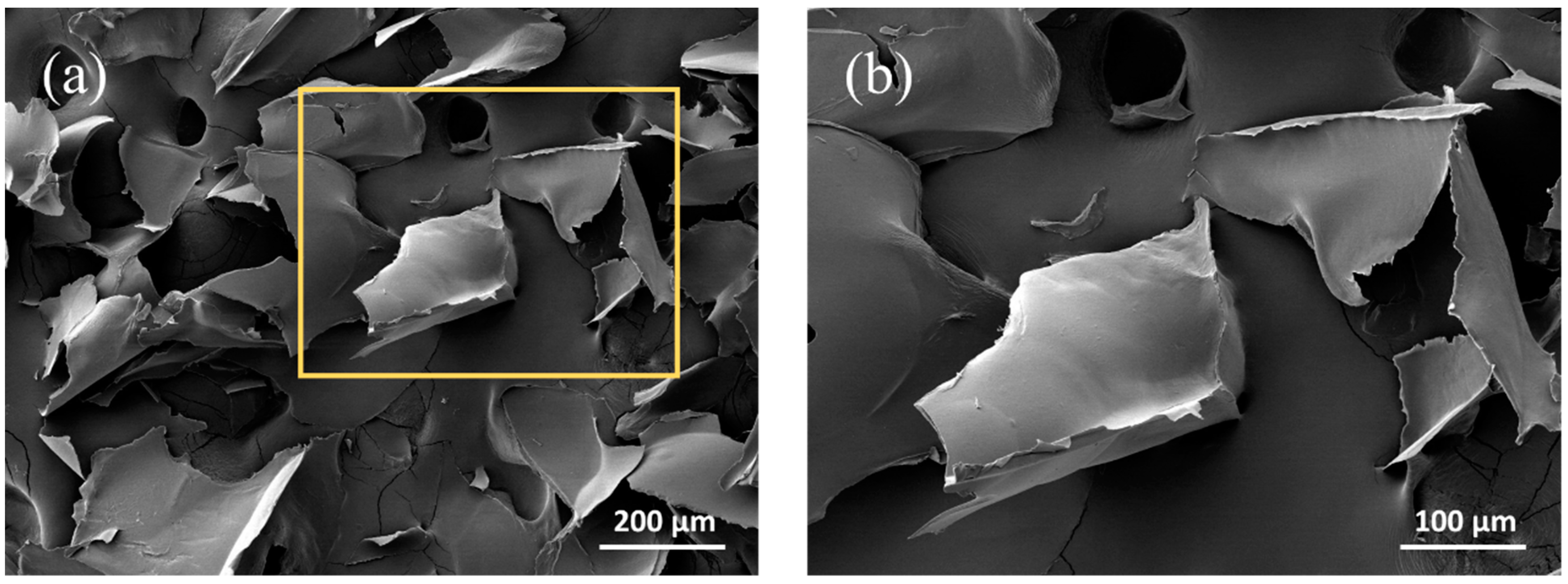
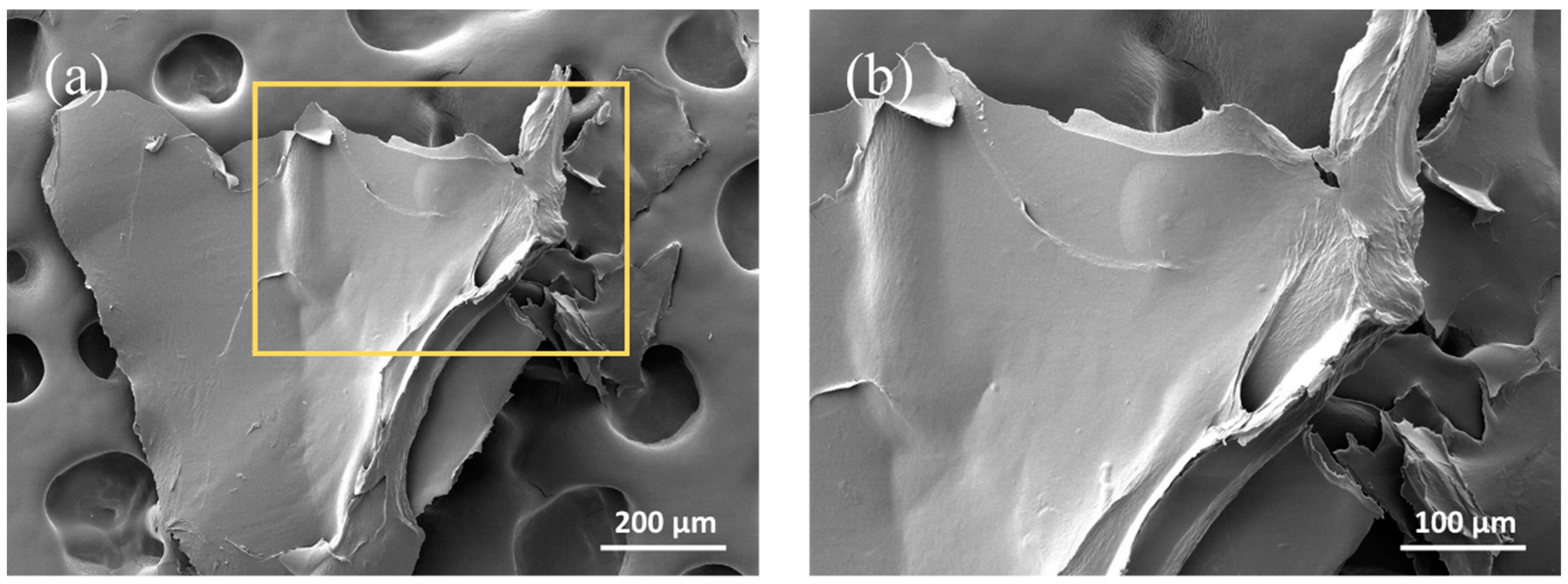
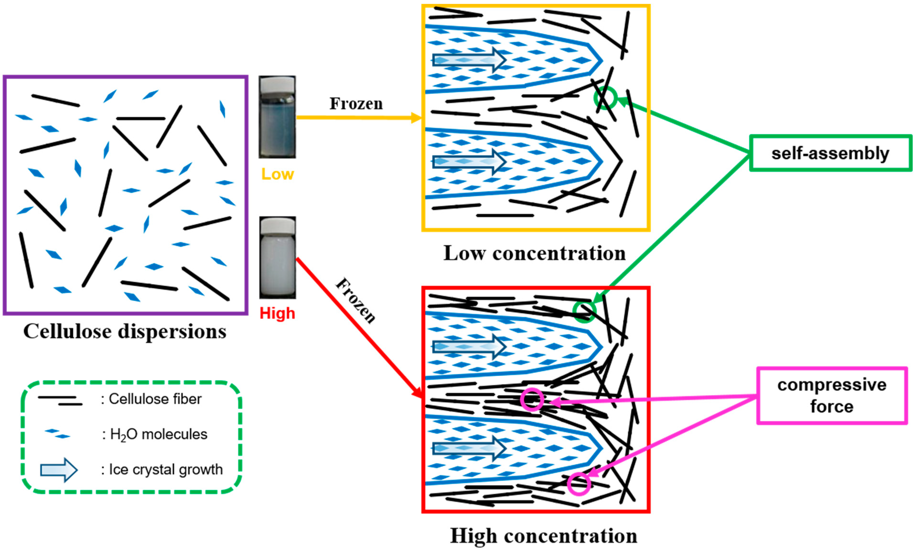
The SEM images showed that the morphology of the CNC powder, which was obtained by lyophilization processes, was a large-sized agglomerate at low and high concentrations (Figure 3 and Figure 4). Cellulose nanocrystals with nanoscale units have a very large specific surface area and high surface energy, resulting in CNC self-agglomerations during processing [31]. Also, in the rapid-freezing process of CNC suspension, water quickly releases heat and solidifies to a crystalline state at −80 °C. In this process, the molecular arrangement of water forms ice crystals, and the growth direction of ice crystals goes from the outside of the container to the inside. This is consistent with the previous findings that as the crystals grow, the arrangement of water molecules in the vessel changes, the volume of the solvent expands, and subsequently, the CNCs suspended in the solvent are subject to compressive stress due to the volume expansion of the surrounding ice crystal growth [32]. The CNCs are then aligned in the chiral-nematic phase, forming and concentrating lamellae. As a result, CNC lamellae bundles are formed by the self-aggregations of CNCs and the compressive stresses generated during cryogenic freezing. Figure 5 shows a schematic diagram of the above-described mechanism.
This aspect of CNC microlamellae formation depended on the concentration of the CNC suspension being frozen. The higher the concentration of the CNC suspension, the shorter the physical distance between the CNCs and the higher the possibility of self-aggregation. Thus, when frozen, the ice crystal growth caused more condensation due to the physical compressive force, forming a larger and thicker lamella (Figure 4). SEM images (×100) showed that CNC particles formed at a high CNC lyophilization concentration (2.2%) were >500 µm, whereas CNC particles formed at a low CNC lyophilization concentration (1%) were 100~200 µm. In addition, the high magnification SEM image (×300) showed that single-layered thin lamellae were observed in the CNC particles lyophilized at the low concentration. However, the CNCs lyophilized at the high concentration were thicker, formed particles consisting of multiple layers, and showed CNC agglomerations on the lamella surface. These thick and large CNC particles, which were formed during the lyophilization process, could be the reason for the relative reduction of the filler effect in the composite matrix.

3.1.2. Morphological Properties of CNC/Photopolymer Composites Processed at Different CNC Lyophilization Concentrations

The SEM images of the fracture surfaces of CNC/photopolymer composites showed that the composites with CNCs processed at a low CNC lyophilization concentration (1%) had smoother surfaces than the composites with CNCs processed at a high CNC lyophilization concentration (2.2%) (Figure 6, Figure 7, Figure 8 and Figure 9). Additionally, comparing agglomerated CNC particles on the matrix, the composites with CNCs processed at the low concentration showed smaller and more uniform shapes of CNC particles. However, the composites with CNCs processed at the high concentration showed wider sizes of CNC particles, exhibiting overall rough and uneven surfaces. For the composite with 0.5% CNCs processed at the low concentration, CNC particles of 200–300 µm, which were generated during cryogenic freezing, were broken into rod-like particulates through a series of pretreatments and were present in the composite at approximately 3 µm in width. However, in the case of the composites with CNCs processed at the high concentration, the deformation of the agglomerated CNCs occurred less frequently, resulting in >10 µm width of CNCs on the fracture surface. In particular, the above-mentioned phenomenon was more prominent in the composites with 1.0 wt% CNCs, and the stress was concentrated on the large CNC particles at the time of fracture. Hence, the interfacial bonding between the resin matrix and the CNC particles was reduced, resulting in a gap.

3.1.3. Mechanical Properties of CNC/Photopolymer Composites Processed at Different CNC Lyophilization Concentrations

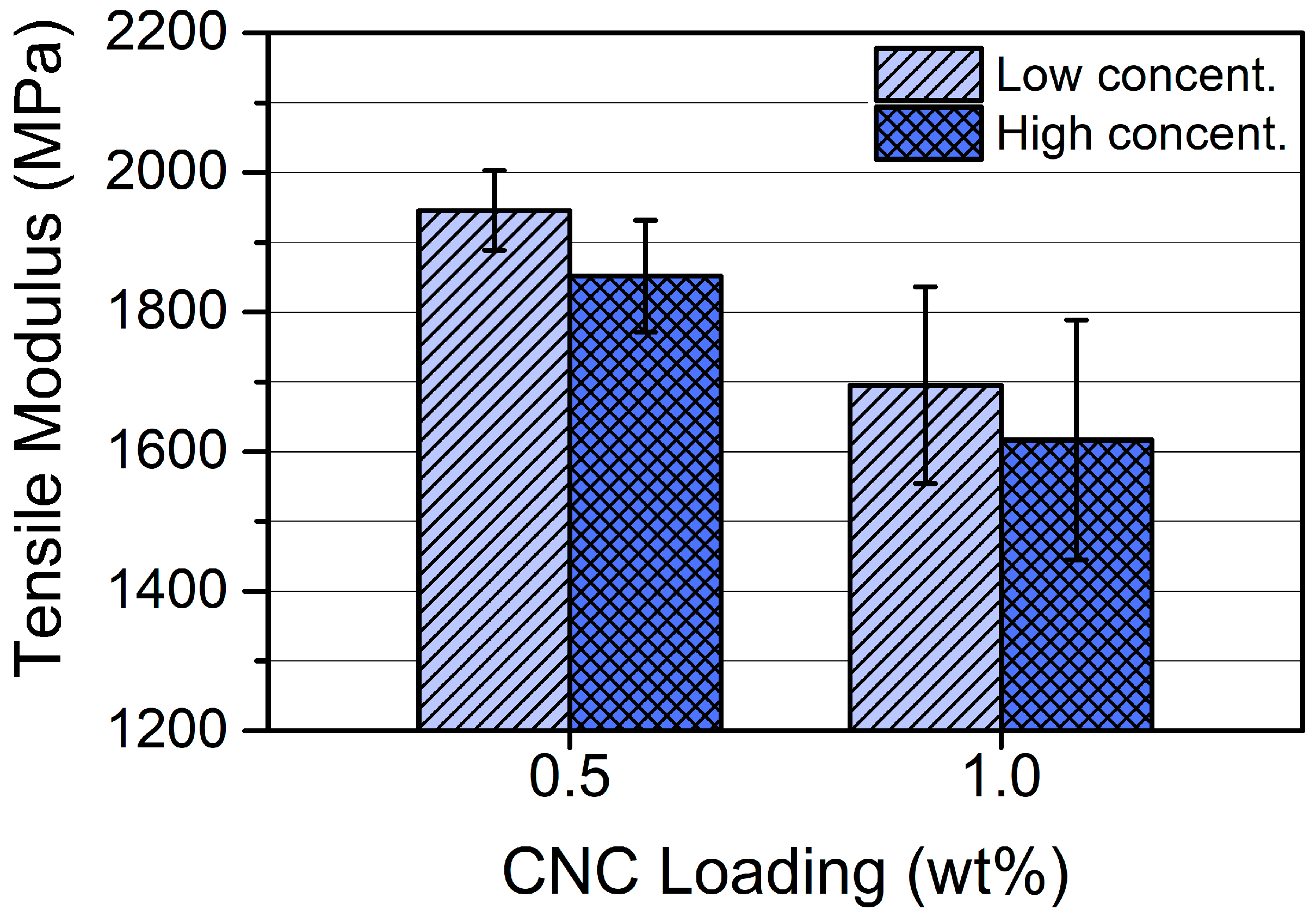
The same amount of CNC incorporations into photopolymer composites resulted in higher tensile strength and tensile modulus values at a low CNC lyophilization concentration (1%) compared to a high CNC lyophilization concentration (2.2%) (Figure 10 and Figure 11). The reason for this seemed to be due to the shapes of the added CNC particles. In the case of CNCs lyophilized at the low concentration, the condensed CNC shapes after lyophilization could be thinner and smaller, which may be easy to form more uniform and smaller CNC particles in the same pretreatment process. As a result, the CNC particles maintain smaller and more uniform size distributions when added to the composites. Importantly, it is advantageous to have a high aspect ratio to be an effective stress carrier in the composite. As shown in the SEM images of the fracture surfaces of CNC/photopolymer composites, the CNCs lyophilized at the high concentration had relatively lower aspect ratios than those lyophilized at the low concentration. Therefore, the composites with CNCs treated at the low lyophilization concentration were considered to have higher mechanical properties than the composites with CNCs treated at the high lyophilization concentration due to more efficient fracture and dispersion mechanisms.
Additionally, lower tensile strength and tensile modulus values were observed in the composite with a high CNC loading (1.0 wt%). As confirmed by the morphological characteristics, the higher the amount of CNCs added, the less effective the dispersion and destruction mechanisms of the pretreatment process, resulting in larger sizes and lower aspect ratios, and consequently lower strength values. Besides, the sizes of CNC particles dispersed in the composites with 1.0 wt% CNCs were not even. Thus, it seemed that the stress was concentrated in the CNC particles, leading to a decrease in the strength values. Therefore, the CNCs processed at the low lyophilization concentration of 1% were selected for the CNC/photopolymer composites in later experiments.

3.2. Effect of CNC Contents on the Photopolymer Composites

3.2.1. Mechanical Properties of CNC/Photopolymer Composites with Various CNC Loading Levels

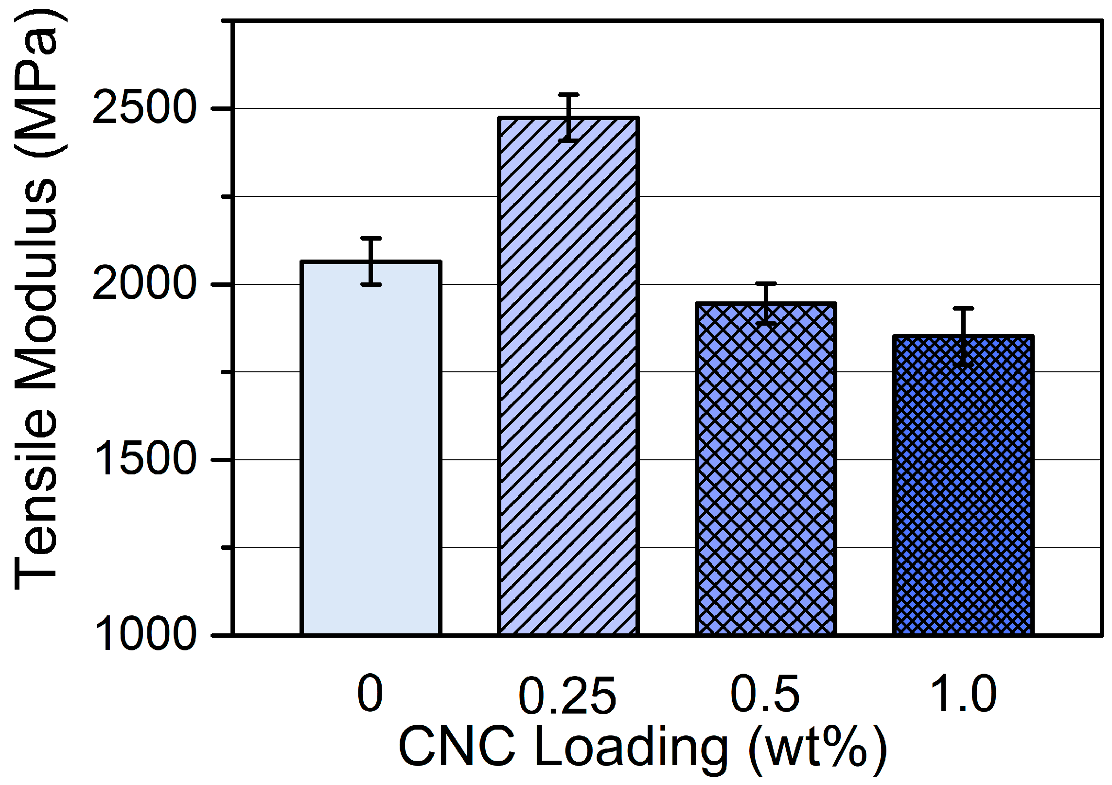
The tensile strength of 0.25 wt% CNC/photopolymer composite was 30 MPa, indicating a 20% increase in tensile strength compared to the photopolymer composite without CNC particles (Figure 12). However, the incorporation of more than 0.25 wt% of CNCs did not show an improvement in tensile strength of the composites, but rather reduced the strength values. The tensile modulus of 0.25 wt% CNC/photopolymer composite was 2474 MPa, and it had 20% higher tensile modulus than the neat photopolymer composite (Figure 13). However, CNC/photopolymer composites with higher CNC loading levels (i.e., 0.5 and 1.0 wt%) showed lower tensile modulus values compared to the neat photopolymer composite, resulting in 5.7% and 10.3% reductions in modulus values, respectively.
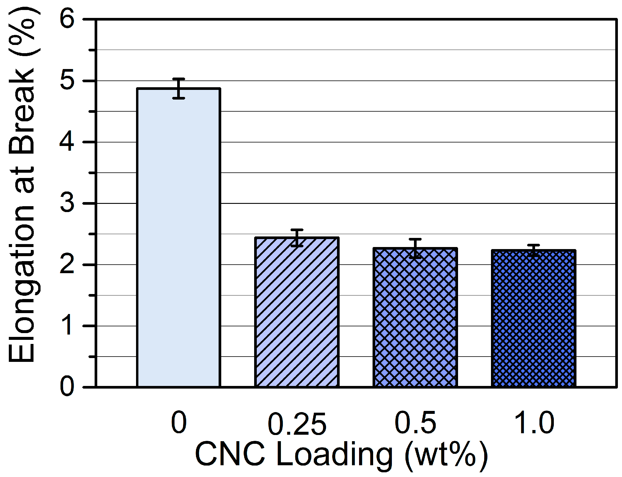
This tendency seemed to be due to the difference in the reinforcement effect of the CNC dispersion. The high tensile strength value at a relatively low CNC loading level (i.e., 0.25 wt%) more effectively accommodated the effects of the dispersion mechanism. This is probably because the loaded CNC particles had smaller and more evenly distributed size and shape, leading to even and uniform dispersions, and consequently served as an efficient stress carrier. However, elongation at break values tended to decrease with an increasing amount of CNCs, indicating that the excessive CNC additions resulted in the lowered ductility and increased stiffness of the photopolymer composites (Figure 14). When a stress was transferred to the CNC particles, the rigid CNCs were subjected to a significant amount of stress. This effect allowed the less stiff photopolymer to accept a small percentage of residual load through the CNC particles. With 180° beta-acetal bonding of carbon atoms, the CNC is inherently rigid, which provides adequate structural stability to mechanical resistance and meets the demand for intermolecular hydrogen bonding for higher stability [33,34,35].
In addition, owing to the dissolution of the amorphous regions of the microfibrils during the CNC extraction process, the crystallinity of the CNC is further increased, even above 90%, which further improves the stiffening performance of the CNC [36]. Due to this very high stiffness, the CNC particles can sustain the additional stress transferred from the polymer matrix. The variation in mechanical performance between 0.25 wt% CNC and higher CNC loading levels (i.e., 0.5 and 1.0 wt%) can be explained by the free volume principle of the composites. As the CNC concentration increases, the volume fraction of the CNC increases, but the free volume decreases and the distance between adjacent CNCs decreases. As a result, they may accept inadequate polymer chains with limited mobility, which significantly affects the fracture mechanism of the photopolymer composites. In addition, the various mechanical performances observed in the photopolymer composites with more than 0.25 wt% CNC may affect the CNC orientation in the photopolymer resin network. Depending on the completeness of the CNC alignment in the resin polymer, its contribution to mechanical strength can vary, which is a factor that can be drastically changed by using DLP 3D printing.

3.2.2. Morphological Properties of CNC/Photopolymer Composites with Various CNC Loading Levels

In a photopolymer composite without CNCs, no impurities or cracks were found, giving a smooth and clean surface (Figure 15a). This is a common brittle fracture failure found in pure photo-polymerized composites. In the composite fracture surface containing 0.25 wt% CNC, dispersed CNCs were the smallest in size and number, so a smooth and flat surface was still observed (Figure 15b). On the fracture surface of the composite with relatively higher amounts of CNC (i.e., 0.5 and 1.0 wt%), the sizes of the aggregated CNCs were larger, and their distribution frequency was higher (Figure 15c,d). As the CNC loading levels increased, larger shapes and reduced dispersions of CNC aggregates were observed, which may support the results of the previous mechanical strength properties.

3.3. Effect of Inorganic Nanofillers on CNC/Photopolymer Composites

3.3.1. Mechanical Properties of Photopolymer Composites with CNC and/or Inorganic Nanofillers

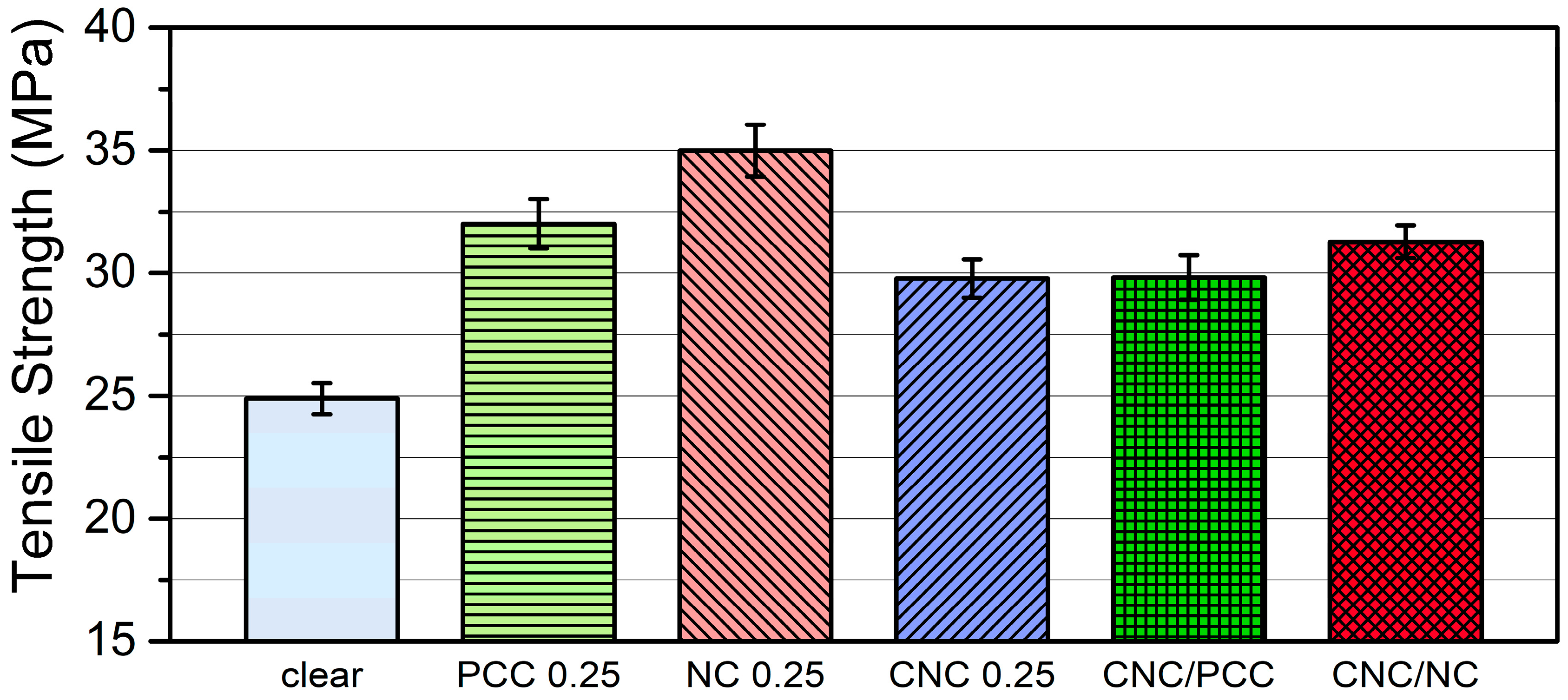
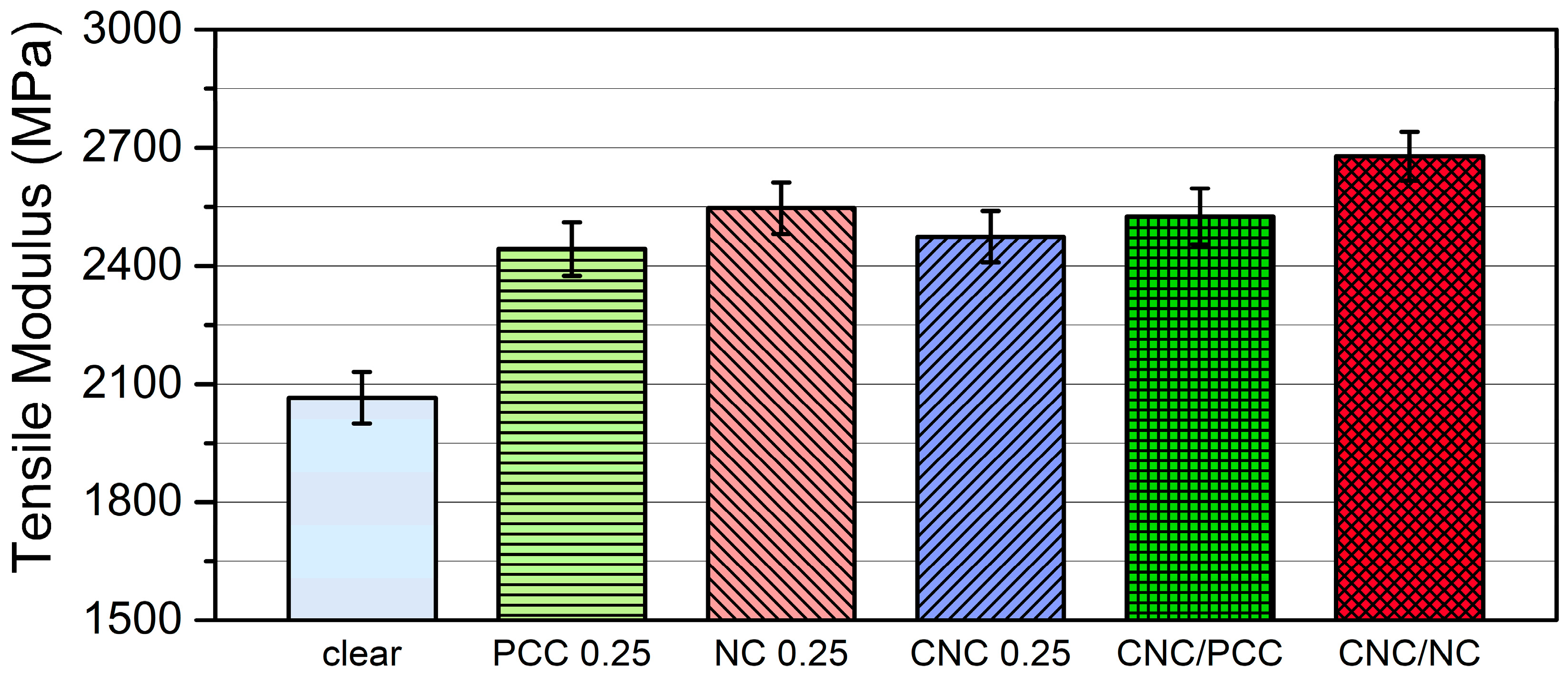
In comparison with the tensile strength of a pure photopolymer composite, the tensile strengths of the composites filled with inorganic nanofillers showed 32 MPa (28.6% increase) for nano-PCC and 35 MPa (40% increase) for nanoclay at 0.25 wt% loading level, respectively (Figure 16). It means that the effect of inorganic nanofillers was greater than that of CNC particles on the tensile strengths of composites at the same filler loading level, which indicated that the reinforcing effect of the inorganic nanofillers was excellent. In other words, theoretically the particle size and size distribution of initial cellulose nanocrystal materials are pretty good enough to reinforce DLP 3D-printed composites because of the length, diameter, and aspect ratio of rod-like CNC dispersions were 100~150 nm, 9~14 nm, and around 10, respectively. However, after freeze-drying process of the CNC dispersions, the lyophilized CNC forms were turned into micrometer scale as they were aggregated or agglomerated. Hence, the freeze-dried CNC particles did not act as good reinforcing nanofillers in filled composites. Also, the properly dispersed nano-PCC or nanoclay particles exhibited better compatibility with the polymer matrix by organo-modifying the surface of each particle, which prevented the self-aggregation of nanoscale particles. These kinds of things subsequently led to better mechanical strength properties. In particular, the nanoclay/photopolymer composite showed the highest tensile strength and tensile modulus compared to the nano-PCC/photopolymer composite (Figure 16 and Figure 17), which can be explained by the shapes and dispersions of the inorganic nanofillers in the matrix. Nano-PCC and nanoclay particles have very small nano-units, and when they are evenly dispersed in composites, they provide remarkable toughness and rigidity to polymer resins, enabling the improvement of mechanical properties. However, these reinforcing effects resulted in somewhat different mechanical properties between nano-PCC/photopolymer and nanoclay/photopolymer composites. In the case of the nano-PCC/photopolymer composite, nano-PCC particles were evenly distributed in the polymer matrix, and these good dispersions were confirmed by SEM images. Also, the nano-PCC particles can increase the density of photopolymer composites and efficiently transfer loads or stresses to give the composites rigidity and toughness, resulting in better mechanical properties.
Similar to the nano-PCC/photopolymer composite, the nanoclay particles in the nanoclay/photopolymer composite were also found to be evenly dispersed by SEM images, but the nanoclay had a plate-like shape (diameter <6 µm) different from the nano-PCC (diameter 40 nm) featuring a cubic particulate shape. Hence, the nanoclay particles seemed to play a role in obstructing the direction of stress transfer occurring during tensile failure. In other words, the nano-PCC/photopolymer composite received an appropriate load and then quickly transferred it to other nearby nano-PCC particles, distributing the load and inducing a reinforcing effect. However, in the case of plate-shaped nanoclay, the received stress was high, but the residual stress to be delivered was low. In addition, the amount of stress dissipation within the composite was higher because the stress detoured to the platelet structure of the nanoclay, and it was repeated inside the composite. This is the structural difference between nano-PCC/photopolymer and nanoclay/photopolymer, which may be attributed to the higher aspect ratio of nanoclays [37].
The composites with both CNC and inorganic nanofillers had lower tensile strength values than the composites with inorganic nanofiller only. This is because the size and shape of the added CNCs was not as small as nanoscale and the CNCs was not evenly dispersed. Thus, the stress transfer mechanism described above negatively affected on the tensile strength. Unlike tensile strength, the tensile modulus represented a higher value for CNC filled composites, especially for CNC/nanoclay/photopolymer composite. It is believed that the CNCs having a high crystallinity and stiffness act synergistically with inorganic nanofillers, thereby imparting improved rigidity to the composite.
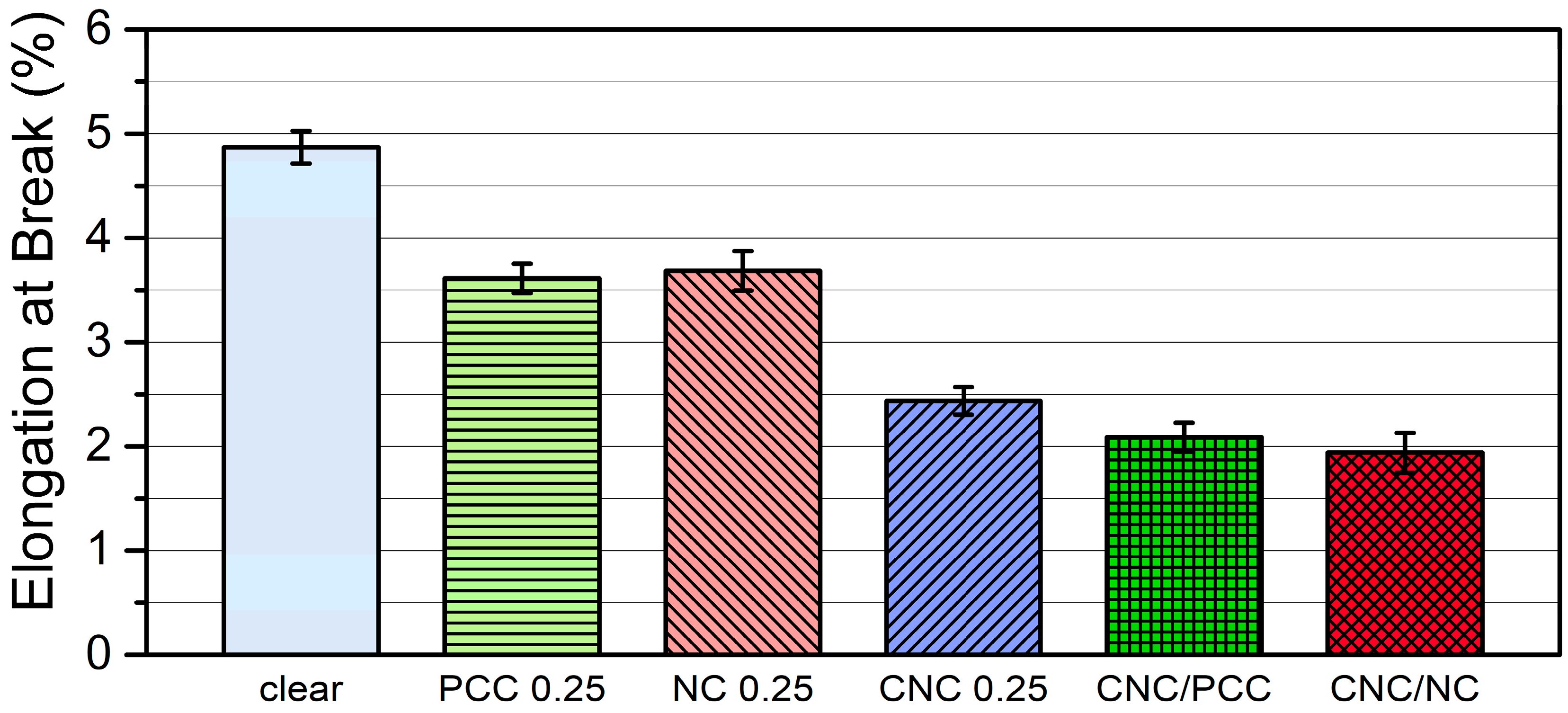
For the elongation at break (Figure 18), the composites with inorganic nanofillers showed lower values than the pure resin composites because the inorganic nanofillers gave the composites rigidity and reduced ductility. In addition, voids were generated around the evenly distributed inorganic particles in the composites during the tensile test, and they had a negative effect on the elongation of the composites [38]. Moreover, with the addition of CNC particles, this trend was exacerbated, resulting in a 50% reduction in elongation at break compared to pure resin.
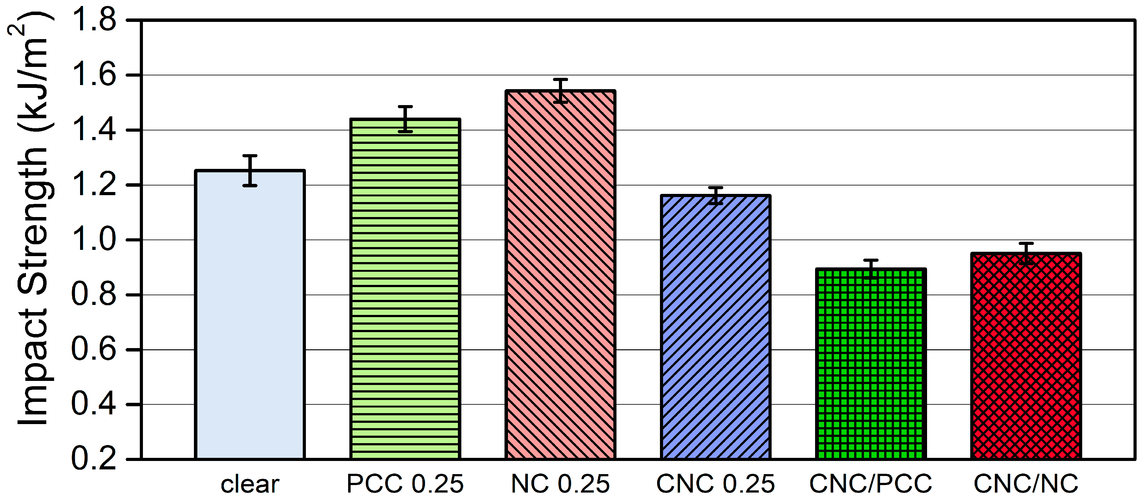
Impact strength also showed toughening effects by inorganic nanofillers, resulting in strength improvements of about 15% for nano-PCC and about 23% for nanoclay (Figure 19) [39]. Composites with CNCs had lower impact strength values compared to the composites with inorganic nanofiller only. The addition of CNC particles to the photopolymer resin negatively affected the impact strength value of the composite. Impact strength is the capability of a material to withstand a suddenly applied load, and it is expressed in terms of energy. In the case of the composites filled with CNCs, the CNCs act as impurities in the composite matrix, and sudden strong loads are concentrated on the CNCs, causing instantaneous fracture and weakened impact resistance. Additionally, when the CNCs are added to the photopolymer resin with inorganic nanofillers, the ductility of the composites is further lowered. Therefore, the stress concentration by CNC particles is accelerated, and the impact strength is accordingly decreased.

3.3.2. Morphological Properties of Photopolymer Composites with CNC and/or Inorganic Nanofillers

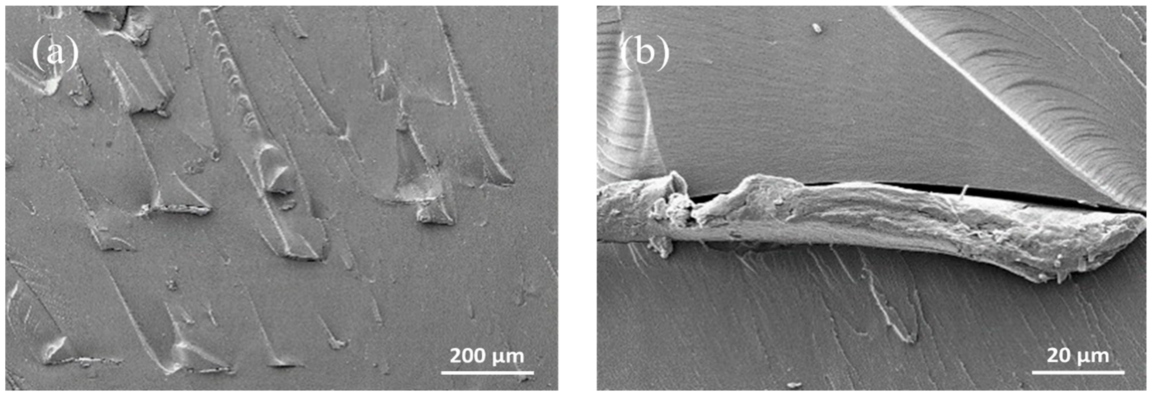
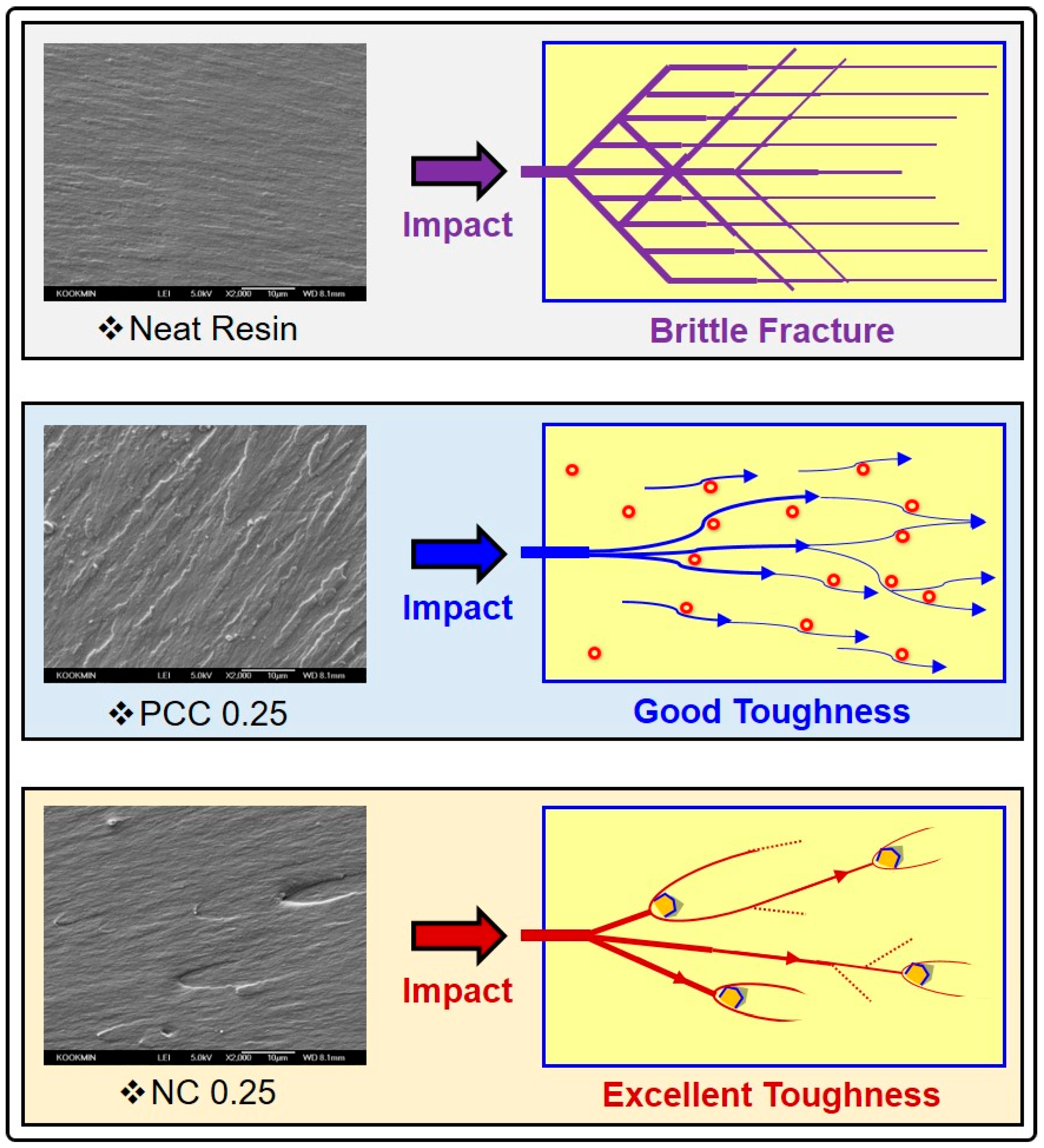
Pure photopolymer composite had a smooth and homogeneous fracture surface, which resulted in no defects or other distinctive features (Figure 20). But, in the case of the composite with 0.25 wt% nano-PCC, the stress transfer direction was remarkable on the fracture surface, and for the composite with 0.25 wt% nanoclay, specific forms to infer orientation were observed (Figure 21 and Figure 22). However, there was a difference in the fracture surface orientations of the composites filled with inorganic nanofillers. The fracture of the composite filled with 0.25 wt% nano-PCC proceeded rapidly at the place where the nano-PCC fracture started, and then passed through the nano-PCC particles, and consequently, thin and long shaped fracture traces with uniform frequency were found. On the other hand, the composite filled with 0.25 wt% nanoclay appeared to spread the polymer fracture as it passed through the plate-shaped nanoclay present in the polymer matrix.
Also, compared to the composite with nano-PCC, the fracture features of the composite with nanoclay were wider and shorter. The fracture failure patterns described above may explain the stress transfer mechanism mentioned in the mechanical properties. For the composite with nano-PCC, when the stress was transferred to individual cubic-like nano-PCC particles, appropriate loads were transferred to the nano-PCC particles, and the residual loads were turned sideways so that stress transfers developed in the original fracture propagation orientations. However, nanoclays have wider high-aspect-ratio layers to accommodate the transmitted stresses, which prevent the straight development of fractures. Thus, the nanoclays could accommodate large stresses and the stresses might be dissipated in composites. As shown in Figure 23, the different stress transfer mechanism models of these inorganic nanofillers provide a supporting basis for the mechanical strength values evaluated in this study.

4. Conclusions

Highly functional nanoscale materials (CNCs, nano-PCC, and nanoclay) were added to liquid photocurable resins, and then the resin blends were 3D-printed to manufacture various photopolymer composites.
To investigate the behaviors of the CNC particles processed in two different CNC lyophilized concentrations and the CNC-reinforced composites, morphological and mechanical properties were analyzed. Relatively small CNC monolayer particles were formed at a low lyophilized concentration of 1%, but larger multi-layered CNC particles were observed at a high lyophilized concentration of 2.2%. Hence, the higher lyophilized concentration resulted in larger and more heterogeneous CNC particle distributions in the filled composites, leading to lower strength properties. Thus, the 1% CNC lyophilization concentration was selected for further research. Also, at the same lyophilization concentration, the higher the CNC loading levels in filled composites, the worse the morphological properties and the lower the mechanical strength properties. The best mechanical strength was observed at the least amount of CNC loading level (0.25 wt%).
In addition, nanoclay and nano-PCC were incorporated into the photocurable resin to evaluate the effects of inorganic nanofillers on the morphological and mechanical properties of photopolymer composites. By analyzing the morphological properties, a stress transfer mechanism between the nanoclay and nano-PCC was identified, and the related model was presented. Also, mechanical property improvements of the composite filled with CNC and inorganic nanofillers supported the stress transfer mechanism.
This study proposed a new approach using wood-derived cellulose nanomaterials and inorganic nanofillers in the DLP 3D printing industry where research on 3D printing materials is insufficient.

Author Contributions

Conceptualization, S.-U.B. and B.-J.K.; methodology, S.-U.B. and B.-J.K.; validation, S.-U.B. and B.-J.K.; formal analysis, S.-U.B.; investigation, S.-U.B. and B.-J.K.; data curation, S.-U.B. and B.-J.K.; writing—original draft preparation, S.-U.B. and B.-J.K.; writing—review and editing, S.-U.B. and B.-J.K.; visualization, S.-U.B. and B.-J.K.; supervision, B.-J.K. All authors have read and agreed to the published version of the manuscript.

Funding

This study was carried out with the support of ‘R&D Program for Forest Science Technology (Project No. 2019150B10-2123-0301)’ provided by Korea Forest Service (Korea Forestry Promotion Institute).

Institutional Review Board Statement

Not applicable.

Informed Consent Statement

Not applicable.

Data Availability Statement

Not applicable.

Conflicts of Interest

The authors declare no conflict of interest.

References

  1. Wang, X.; Jiang, M.; Zhou, Z.; Gou, J.; Hui, D. 3D printing of polymer matrix composites: A review and prospective. Compos. Part B Eng. 2017, 110, 442–458. [Google Scholar] [CrossRef]
  2. Sames, W.J.; List, F.A.; Pannala, S.; Dehoff, R.R.; Babu, S.S. The metallurgy and processing science of metal additive manufacturing. Int. Mater. Rev. 2016, 61, 315–360. [Google Scholar] [CrossRef]
  3. Ngo, T.D.; Kashani, A.; Imbalzano, G.; Nguyen, K.T.Q.; Hui, D. Additive manufacturing (3D printing): A review of materials, methods, applications and challenges. Compos. Part B Eng. 2018, 148, 172–196. [Google Scholar] [CrossRef]
  4. Ayrilmis, N. Effect of layer thickness on surface properties of 3D printed materials produced from wood flour/PLA filament. Polym. Test. 2018, 71, 163–166. [Google Scholar] [CrossRef]
  5. Ntousia, M.; Fudos, I. 3D Printing Technologies & Applications: An Overview. In Proceedings of the CAD 2020 Conference, Singapore, 24–26 June 2019; pp. 243–248. [Google Scholar] [CrossRef]
  6. Utela, B.; Storti, D.; Anderson, R.; Ganter, M. A review of process development steps for new material systems three dimensional printing (3DP). J. Manuf. Process. 2008, 10, 96–104. [Google Scholar] [CrossRef]
  7. Prabhakar, M.M.; Saravanan, A.K.; Lenin, A.H.; Leno, I.J.; Mayandi’, K.; Ramalingam, P.S. A short review on 3D printing methods, process parameters and materials. Mater. Today Proc. 2021, 6108–6114. [Google Scholar] [CrossRef]
  8. Gonzalez, G.; Chiappone, A.; Roppolo, I.; Fantino, E.; Bertana, V.; Perrucci, F.; Scaltrito, L.; Pirri, F.; Sangermano, M. Development of 3D printable formulations containing CNT with enhanced electrical properties. Polymer 2017, 109, 246–253. [Google Scholar] [CrossRef]
  9. Wu, C.; Yi, R.; Liu, Y.-J.; He, Y.; Wang, C.C. Delta DLP 3D printing with large size. In Proceedings of the 2016 IEEE/RSJ International Conference on Intelligent Robots and Systems (IROS), Daejeon, Korea, 1 December 2016; pp. 2155–2160. [Google Scholar]
  10. Patel, D.K.; Sakhaei, A.H.; Layani, M.; Zhang, B.; Ge, Q.; Magdassi, S. Highly Stretchable and UV Curable Elastomers for Digital Light Processing Based 3D Printing. Adv. Mater. 2017, 29. [Google Scholar] [CrossRef]
  11. He, R.; Liu, W.; Wu, Z.; An, D.; Huang, M.; Wu, H.; Jiang, Q.; Ji, X.; Wu, S.; Xie, Z. Fabrication of complex-shaped zirconia ceramic parts via a DLP-stereolithography-based 3D printing method. Ceram. Int. 2018, 44, 3412–3416. [Google Scholar] [CrossRef]
  12. Klemm, D.; Kramer, F.; Moritz, S.; Lindström, T.; Ankerfors, M.; Gray, D.; Dorris, A. Nanocelluloses: A New Family of Nature-Based Materials. Angew. Chem. Int. Ed. 2011, 50, 5438–5466. [Google Scholar] [CrossRef]
  13. Gwon, J.-G.; Cho, H.-J.; Lee, D.; Choi, D.-H.; Lee, S.; Wu, Q.; Lee, S.-Y. Physicochemical and mechanical properties of polypropylene-cellulose nanocrystal nanocomposites: Effects of manufacturing process and chemical grafting. Bioresources 2018, 13, 1619–1636. [Google Scholar] [CrossRef]
  14. Li, V.C.-F.; Kuang, X.; Mulyadi, A.; Hamel, C.M.; Deng, Y.; Qi, H.J. 3D printed cellulose nanocrystal composites through digital light processing. Cellulose 2019, 26, 3973–3985. [Google Scholar] [CrossRef]
  15. Raquez, J.M.; Murena, Y.; Goffin, A.L.; Habibi, Y.; Ruelle, B.; DeBuyl, F.; Dubois, P. Surface-modification of cellulose nanowhiskers and their use as nanoreinforcers into polylactide: A sustainably-integrated approach. Compos. Sci. Technol. 2012, 72, 544–549. [Google Scholar] [CrossRef]
  16. Fukushima, K.; Kimura, Y. Stereocomplexed polylactides (Neo-PLA) as high-performance bio-based polymers: Their formation, properties, and application. Polym. Int. 2006, 55, 626–642. [Google Scholar] [CrossRef]
  17. Purnama, P.; Kim, S.H. Bio-based composite of stereocomplex polylactide and cellulose nanowhiskers. Polym. Degrad. Stab. 2014, 109, 430–435. [Google Scholar] [CrossRef]
  18. Muiruri, J.K.; Liu, S.; Teo, W.S.; Kong, J.; He, C. Highly biodegradable and tough polylactic acid–cellulose nanocrystal composite. Acs Sustain. Chem. Eng. 2017, 5, 3929–3937. [Google Scholar] [CrossRef]
  19. Zhou, C.; Chu, R.; Wu, R.; Wu, Q. Electrospun polyethylene oxide/cellulose nanocrystal composite nanofibrous mats with homogeneous and heterogeneous microstructures. Biomacromolecules 2011, 12, 2617–2625. [Google Scholar] [CrossRef] [PubMed]
  20. Rong, M.Z.; Zhang, M.Q.; Zheng, Y.X.; Zeng, H.M.; Walter, R.; Friedrich, K. Structure–property relationships of irradiation grafted nano-inorganic particle filled polypropylene composites. Polymer 2001, 42, 167–183. [Google Scholar] [CrossRef]
  21. Di Lorenzo, M.L.; Errico, M.E.; Avella, M. Thermal and morphological characterization of poly(ethylene terephthalate)/calcium carbonate nanocomposites. J. Mater. Sci. 2002, 37, 2351–2358. [Google Scholar] [CrossRef]
  22. Wan, C.; Qiao, X.; Zhang, Y.; Zhang, Y. Effect of different clay treatment on morphology and mechanical properties of PVC-clay nanocomposites. Polym. Test. 2003, 22, 453–461. [Google Scholar] [CrossRef]
  23. Kontou, E.; Niaounakis, M. Thermo-mechanical properties of LLDPE/SiO2 nanocomposites. Polymer 2006, 47, 1267–1280. [Google Scholar] [CrossRef]
  24. Kodjie, S.L.; Li, L.; Li, B.; Cai, W.; Li, C.Y.; Keating, M. Morphology and Crystallization Behavior of HDPE/CNT Nanocomposite. J. Macromol. Sci. Part B 2006, 45, 231–245. [Google Scholar] [CrossRef]
  25. Cao, Y.M.; Sun, J.; Yu, D.H. Preparation and properties of nano-Al2O3 particles/polyester/epoxy resin ternary composites. J. Appl. Polym. Sci. 2002, 83, 70–77. [Google Scholar] [CrossRef]
  26. Jo, B.-W.; Park, S.-K.; Kim, D.-K. Mechanical properties of nano-MMT reinforced polymer composite and polymer concrete. Constr. Build. Mater. 2008, 22, 14–20. [Google Scholar] [CrossRef]
  27. Pinnavaia, T.J.; Beall, G.W. Polymer–Clay Nanocomposites; John Wiley & Sons Ltd.: Hoboken, NJ, USA, 2001; 370p. [Google Scholar]
  28. Tsai, J.; Sun, C. Effect of platelet dispersion on the load transfer efficiency in nanoclay composites. J. Compos. Mater. 2004, 38, 567–579. [Google Scholar] [CrossRef]
  29. Tjong, S.; Bao, S. Impact fracture toughness of polyamide-6/montmorillonite nanocomposites toughened with a maleated styrene/ethylene butylene/styrene elastomer. J. Polym. Sci. Part B Polym. Phys. 2005, 43, 585–595. [Google Scholar] [CrossRef]
  30. Cho, J.; Paul, D.R. Nylon 6 nanocomposites by melt compounding. Polymer 2001, 42, 1083–1094. [Google Scholar] [CrossRef]
  31. Brinkmann, A.; Chen, M.; Couillard, M.; Jakubek, Z.J.; Leng, T.; Johnston, L.J. Correlating Cellulose Nanocrystal Particle Size and Surface Area. Langmuir 2016, 32, 6105–6114. [Google Scholar] [CrossRef] [Green Version]
  32. Han, J.Q.; Zhou, C.J.; Wu, Y.Q.; Liu, F.Y.; Wu, Q.L. Self-Assembling Behavior of Cellulose Nanoparticles during Freeze-Drying: Effect of Suspension Concentration, Particle Size, Crystal Structure, and Surface Charge. Biomacromolecules 2013, 14, 1529–1540. [Google Scholar] [CrossRef]
  33. Eichhorn, S.J.; Dufresne, A.; Aranguren, M.; Marcovich, N.; Capadona, J.; Rowan, S.; Weder, C.; Thielemans, W.; Roman, M.; Renneckar, S. Current international research into cellulose nanofibres and nanocomposites. J. Mater. Sci. 2010, 45, 1–33. [Google Scholar] [CrossRef] [Green Version]
  34. Moon, R.J.; Martini, A.; Nairn, J.; Simonsen, J.; Youngblood, J. Cellulose nanomaterials review: Structure, properties and nanocomposites. Chem. Soc. Rev. 2011, 40, 3941–3994. [Google Scholar] [CrossRef] [PubMed]
  35. Börjesson, M.; Westman, G. Chapter 7. Crystalline nanocellulose—Preparation, modification, and properties, Cellulose—Fundamental Aspects and Current Trends; IntechOpen Limited: London, UK, 2015; pp. 159–191. [Google Scholar] [CrossRef] [Green Version]
  36. Miao, C.; Hamad, W.Y. Cellulose reinforced polymer composites and nanocomposites: A critical review. Cellulose 2013, 20, 2221–2262. [Google Scholar] [CrossRef]
  37. Lam, C.-K.; Lau, K.-T.; Cheung, H.-Y.; Ling, H.-Y. Effect of ultrasound sonication in nanoclay clusters of nanoclay/epoxy composites. Mater. Lett. 2005, 59, 1369–1372. [Google Scholar] [CrossRef]
  38. Lee, D.; Kim, S.; Kim, B.-J.; Chun, S.-J.; Lee, S.-Y.; Wu, Q. Effect of nano-CaCO3 and Talc on property and weathering performance of PP composites. Int. J. Polym. Sci. 2017, 2017, 9–17. [Google Scholar] [CrossRef] [Green Version]
  39. Kim, B.C.; Park, S.W. Fracture toughness of the nano-particle reinforced epoxy composite. Compos. Struct. 2008, 86, 69–77. [Google Scholar] [CrossRef]
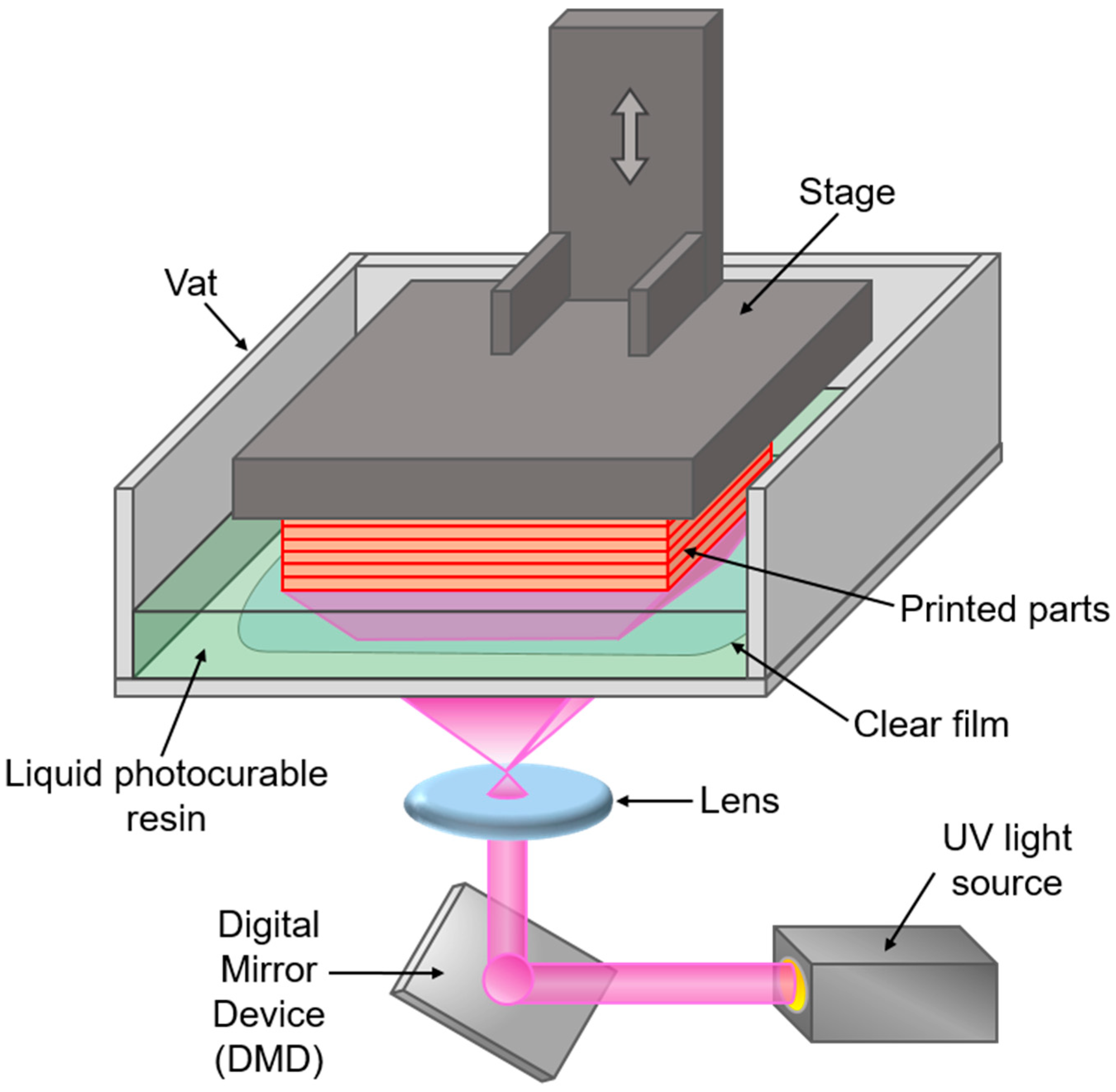
Figure 1. Schematic diagram of DLP type 3D printer configuration.
Applsci 11 06835 g001
Figure 2. Pictures of DLP 3D printer (exterior and interior photos) and 3D-printed composites.
Applsci 11 06835 g002
Figure 3. SEM images of lyophilized CNCs processed at a low concentration: (a) ×100 and (b) ×300.
Applsci 11 06835 g003
Figure 4. SEM images of lyophilized CNCs processed at a high concentration: (a) ×100 and (b) ×200.
Applsci 11 06835 g004
Figure 5. Mechanism of the lyophilization-induced self-assembling behavior of CNCs during the freeze-drying process.
Applsci 11 06835 g005
Figure 6. SEM images of 0.5 wt% CNC/photopolymer composites processed at a low CNC lyophilization concentration: (a) ×50 and (b) ×2000.
Applsci 11 06835 g006
Figure 7. SEM images of 0.5 wt% CNC/photopolymer composites processed at a high CNC lyophilization concentration: (a) ×50 and (b) ×2000.
Applsci 11 06835 g007
Figure 8. SEM images of 1.0 wt% CNC/photopolymer composites processed at a low CNC lyophilization concentration: (a) ×100 and (b) ×1000.
Applsci 11 06835 g008
Figure 9. SEM images of 1.0 wt% CNC/photopolymer composites processed at a high CNC lyophilization concentration: (a) ×100 and (b) ×1000.
Applsci 11 06835 g009
Figure 10. Tensile strength of CNC/photopolymer composites as a function of lyophilized CNC concentration and CNC loading.
Applsci 11 06835 g010
Figure 11. Tensile modulus of CNC/photopolymer composites as a function of lyophilized CNC concentration and CNC loading.
Applsci 11 06835 g011
Figure 12. Tensile strength of CNC/photopolymer composites with various CNC loading levels.
Applsci 11 06835 g012
Figure 13. Tensile modulus of CNC/photopolymer composites with various CNC loading levels.
Applsci 11 06835 g013
Figure 14. Elongation at break of CNC/photopolymer composites with various CNC loading levels.
Applsci 11 06835 g014
Figure 15. SEM images (×200) of CNC/photopolymer composites with various CNC loading levels: (a) 0 wt%, (b) 0.25 wt%, (c) 0.5 wt%, and (d) 1.0 wt%.
Applsci 11 06835 g015
Figure 16. Tensile strength of composites filled with CNC and/or inorganic nanofillers.
Applsci 11 06835 g016
Figure 17. Tensile modulus of composites filled with CNC and/or inorganic nanofillers.
Applsci 11 06835 g017
Figure 18. Elongation at break of composites filled with CNC and/or inorganic nanofillers.
Applsci 11 06835 g018
Figure 19. Impact strength of composites filled with CNC and/or inorganic nanofillers.
Applsci 11 06835 g019
Figure 20. SEM images of a neat photopolymer composite: (a) ×500 and (b) ×10,000.
Applsci 11 06835 g020
Figure 21. SEM images of a composite filled with 0.25 wt% nano-PCC: (a) ×500 and (b) ×10,000.
Applsci 11 06835 g021
Figure 22. SEM images of a composite filled with 0.25 wt% nanoclay: (a) ×500 and (b) ×10,000.
Applsci 11 06835 g022
Figure 23. Stress transfer mechanism models by inorganic nanofillers in filled composites.
Applsci 11 06835 g023
Table 1. Compositions and formulation ratios of photopolymer composites.
Sample NameComposition Based on Weight (wt%)
Photocurable ResinCNCNano-PCCNanoclay
Neat resin100---
CNC 0.2599.750.25--
CNC 0.599.50.5--
CNC 1.0991--
PCC 0.2599.75-0.25-
NC 0.2599.75--0.25
CNC/PCC99.50.250.25-
CNC/NC99.50.25-0.25
Table 2. Pretreatment steps of mixtures before 3D printing.
StepProcessNote
Step–1
(Magnetic stirring)
Premixing and re-dispersion of composition600 rpm, 40 °C, 30 min
Step–2
(Homogenizing)
Physical destruction of CNCs and inorganic nanofillers5000 rpm, 40 °C, 30 min,
Gap between stator and rotator: 35 mm
Step–3
(Ultrasonication: bath)
Dispersion of composition40 kHz, 160 W, 25 °C, 20 min
Step–4
(Ultrasonication: probe)
Dispersion and deformation of lyophilized CNCs20 kHz, 750 W, Amplitude 40 %, 40 °C, 10 min
Step–5
(Ultrasonication: bath)
Dispersion and degassing40 kHz, 160 W, 25 °C, 20 min
Table 3. 3D printing parameters and scale values.
PrinterMiiCraft U125
XY Resolution65 µm
Wavelength405 nm LED
Base Layer1 Layer
Base Curing5000 ms
Buffer Layer5 Layers
Gap Adj.100 µm
Layer Curing1500 ms
Layer Thickness50 µm
CleaningTap water & Ethyl alcohol
Publisher’s Note: MDPI stays neutral with regard to jurisdictional claims in published maps and institutional affiliations.