Abstract
Perovskites have recently attracted interest in the field of solar energy due to their excellent photovoltaic properties. We herein present a new approach to the composition of lead free perovskites via mixing of halide and oxide perovskites that share the cubic ABX3 structure. Using first-principles calculations through Density Functional Theory, we systematically investigated the atomic and electronic structures of mixed perovskite compounds composed of four cubic ABX3 perovskites. Our result shows that the B and X atoms play important roles in their band structure. On the other hand, their valence bands contributed by O-2p, Rh-4p, and Ti-3p orbitals, and their electronic properties were determined by Rh-O and Ti-O bonds. With new understandings of the electronic properties of cubic halide or oxide perovskites, we lastly combined the cubic perovskites in various configurations to improve stability and tune the bandgap to values desirable for photovoltaic cell applications. Our investigations suggest that the mixed perovskite compound Cs2Sn2Cl3I3Sr2TiRhO6 produced a bandgap of 1.2 eV, which falls into the ideal range of 1.0 to 1.7 eV, indicating high photo-conversion efficiency and showing promise towards solar energy applications.
1. Introduction
In response to the increasing demand for solar cells as the source of renewable energy, photovoltaic solar panels based on perovskite semiconductors have been gaining wide attention [1,2,3,4,5]. Perovskite is a calcium titanium oxide mineral, discovered in the Ural Mountains of Russia, that exhibited superior transmission of solar energy compared to silicon or selenium, as high as 27% [6,7,8]. However, the instability of lead within perovskite minerals has introduced new environmental concerns, as temperature or humidity fluctuations can cause toxic lead-based substances to leak into the environment [9,10,11,12,13].
For applications in semiconductors for solar cells, perovskites require strong electronic properties which can be understood from their band structures and bandgap values. Although cubic perovskites possess bandgaps that are suitable for many applications [14,15], the bandgap values are often inadequate for solar cells, and may poorly bond with other components during use. To resolve issues in stability and transmission efficiency, researchers have looked towards halide perovskites, hybrid perovskites, and double perovskites, yet the presence of lead or other toxic components generates environmental concerns [16,17,18,19,20,21,22]. Thus, the search for lead free, nontoxic, and inorganic perovskite materials is an urgent and ongoing research field [23,24].
We herein present a new approach to the composition of lead-free perovskites via mixing of halide and oxide perovskites, enabling tuning of structural stability and bandgap values to design effective photovoltaic materials [25]. Specifically, we mixed, combined, stretched, and compressed various cubic perovskites symmetrically to modify the structural and electronic properties, furthering our understanding of mixed perovskite compounds and improving transmission efficiency [26,27]. To form the mixed perovskite compound, we mixed halide or oxide perovskites that share the same ABX3 structure, where A is a cation with different groups of valence electron configurations, B is a cation chosen from transition metals, and X is either a halide or an oxide [28]. In particular, we selected CsSnCl3, CsSnI3, SrRhO3, and SrTiO3 as exceptional halide or oxide perovskites as they exhibit similar electronic properties. Moreover, halide perovskites can bond strongly to other perovskites within thin films [29]. However, this combination approach provided challenges as perfect cubic symmetry is rather uncommon [30,31,32,33], while the actual bandgap produced by a single cubic perovskite is not theoretically applicable. Lastly, we constructed the mixed perovskite compounds in diverse arrangements and orders to tune the computational bandgap to values ideal for solar cell applications.
2. Calculation Methods
2.1. Computational Details
All first-principle calculations performed in this research were completed within the framework of the Density Functional Theory (DFT) as implemented in the ABINIT [34,35] code. The Generalized Gradient Approximation (GGA) [36] in the Perdew-Burke-Ernzerhof (PBE) [36] form was selected for the Exchange Correlation (XC) functional. For all elements in our calculations, we used the Projected Augmented Wave (PAW) [37] pseudopotentials with projectors generated with the AtomPAW [38,39,40] code. GGA-PBE DFT calculations tend to contain the issue of underestimated bandgaps [41]. As a result, the underestimation may appear in the final result of our calculation, and may therefore suggest higher efficiency than the bandgaps had when tuning the bandgap of mixed perovskites. In light of this and in order to render accurate data, we use Equation (1) to adjust the final value.
Egap(corrected) = (Egap(GGA − PBE) × 1.358 + 0.125) × 0.998 + 0.014
This equation is necessary in order to make comparison between actual material and theoretical calculation [42]. The displayed equation is adjusted to fit the difference between different types of perovskites. The corrected value gives similar result as the experimental values mentioned in Table 1.

Table 1.
Calculated lattice parameter (a) and previous calculations as well as experimental data.
2.2. Materials
As the basic unit cells, we selected from cubic perovskites including CsSnCl3, CsSnI3, SrTiO3, and SrRhO3. To perform computational studies, we first optimized each of the halide or oxide perovskites individually. To investigate the structural and electronic properties of mixed perovskite compounds, we then constructed 2 × 2 × 2 supercells from various configurations of the four cubic perovskites. By studying the effects of various perovskite mixtures on the overall stability and bandgap, we sought to achieve values that were optimal for photovoltaic cell applications.
We performed computations based on PAW pseudopotentials based on the electronic configurations of the elements as displayed in Table 2.
Table 2.
Electron configurations and radius cutoff for generate PAW pseudopotentials atom.
2.3. Convergence Calculations
To perform convergence calculations for the cubic unit cells, we conducted kinetic energy cut off and k-point mesh converged for the abx3 perovskite materials. We performed self-consistent field (scf) cycles until the total energy reached a difference of 1 × 10⁻¹⁰ hartree. We performed these convergence calculations using experimental lattice constants. All variables were considered to be in convergence when the energy difference reached below 0.0001 hartree twice. Then, we determined the fully relaxed parameters and interval coordinates when the maximum dilation was 1.05. These values will be considered in later calculations. Kinetic energy cutoff and k-point mesh convergence of four compounds are displayed in Table 3.
Table 3.
Kinetic energy cut off (ecut), k-point mesh convergence for cubic perovskites.
We then constructed an inorganic cubic 2 × 2 × 1 perovskites supercell (abx3) by combining two halide and two oxide perovskites. We sought to design theoretical mixed perovskite compounds that showed advantageous properties as solar cell materials, including cost-efficiency, structural stability, and ideal bandgap values, as well as to better understand the effects of mixed halide and oxide perovskites on the electronic band structure and bandgap towards photovoltaic applications.
2.4. Band Structures Calculation
We used the relaxed atomic structures shown above to calculate each perovskites band structure. We calculated the band structures along four different high symmetry k-points in the Brillouin Zone, Γ (0,0,0), R (0.5, 0.5, 0.5), X (0, 0.5, 0), and M (0.5, 0.5, 0). Each valence band represents one electron, and we added a total of four conduction bands. The electronic band structure is used to determine the electronic properties of perovskites. We transferred the lattice vectors to reciprocal spaces by using the formula below:
2.5. Formation Energy
We calculated formation energies of our mixed perovskites to investigate the stability of our compounds. We computed the total energies of the single cubic perovskites as well as the 2 × 2 × 1 mixed compounds. The formation energy was calculated using the formula below:
where Emixed represents the total energy of 2 × 2 × 1 mixed perovskites, E1, E2, E3 and E4 represent the energies of the individual cubic perovskites that compose the mixed perovskite compound.
Ef = Emixed − E1 − E1 − E3 − E4
3. General Results and Discussion
3.1. Structural Properties
We chose all four cubic perovskites to possess regular cubic symmetry. The atoms of primary unit cells were positioned at A (0, 0, 0), B (0.5, 0.5, 0.5), X1 (0.5, 0.5, 0), X2 (0.5, 0, 0.5) and X3 (0.5, 0, 0.5). We relaxed lattice parameters including four cubic perovskites and several 2 × 2 × 1 mixed perovskite combinations. The lattice parameters of cubic perovskites were in agreement with previous literature [42,43,44]. The equilibrium lattice parameters (a) are displayed in Table 1. The convergence calculations and calculated lattice parameters revealed that for halide perovskites, smaller halogens resulted in much shorter and stronger bonds compared to larger halogens (Table 1 and Table 2). For example, since Cl has an atomic radius of 1.8032 Bohr and I has an atomic radius of 2.3002 Bohr (Table 2), the Sn-Cl bond is stronger than Sn-I bonds, improving the efficiency of the semiconductor while utilizing cost-efficient materials.
3.2. Pure Materials
To study the electronic properties of the mixed perovskite compounds, we performed band structure studies, total density of states (TDOS) plots, projected density of states (PDOS) plots, as well as fat band analysis at zero pressure. We first individually investigated the four basic compounds that would form mixed 2 × 2 × 1 cubic perovskites, namely CsSnCl3, CsSnI3, SrRhO3, and SrTiO3. These valuable research materials are cost-efficient and effective in both financial and environmental terms. Thus, the resulting mixed compound would be composed of various configurations of halide and oxide cubic perovskites, enabling the bandgap to be tuned to desirable values. We calculated kinetic energy cutoff, k-points mesh and performed band structures, total density of states (TDOS) and projective density of states (PDOS) using GGA-PBE DFT calculations along high symmetry directions in the First Brillouin zone with relaxed but symmetrical structures.
The band structure analysis provided insight into the electronic properties and electronic bands of the cubic perovskites as promising semiconductors. Based on the relaxed parameters and interval coordinates, we respectively calculated band structures and performed fat band calculations along the high symmetry points located at Γ (0, 0, 0), R (0.5, 0.5, 0.5), X (0, 0.5, 0), and M (0.5, 0.5, 0). Figure 1 exhibits the basic structure of a perovskite unit cell and the Brillouin Zone. The Fermi level for all four perovskites were set to zero. Our bandgaps were close to previously reported experimental bandgaps. For the band structures figures, all the peaks are located on the R point (see Figure 2). All cubic perovskites, except for SrRhO3, exhibited bandgaps on the DOS plots. DOS and PDOS plots are all presented in Figure 3.
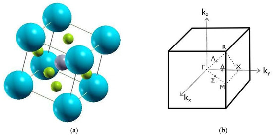
Figure 1.
(a) Cubic structure of formal perovskites. The spheres in the figure are the atoms. The gray atom in the center represents A atoms, the green atoms represent the B atoms, and the blue atoms are the X atoms. (b) First Brillouin zone of cubic crystal structure [42]. High symmetry k-points are Γ (0,0,0), R (0.5, 0.5, 0.5), X (0, 0.5,.0), and M (0.5, 0.5, 0).
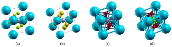
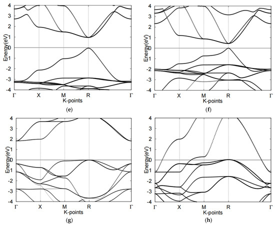
Figure 2.
Electronic band structures of four cubic perovskites (a) CsSnCl3, (b) CsSnI3, (c) SrTiO3, (d) SrRhO3, (e) band structure of CsSnCl3, (f) band structure of CsSnI3. (g) band structure of SrTiO3, (h) band structure of SrRhO3. The Fermi level is set to 0 for all band structures.
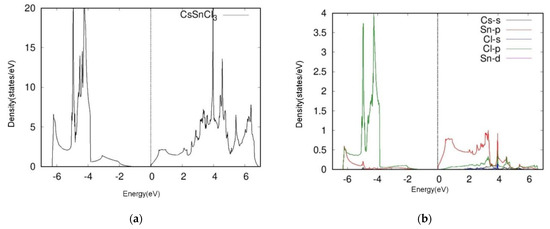
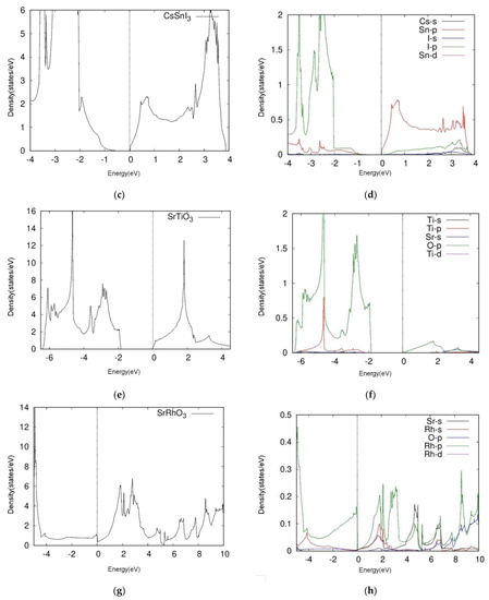
Figure 3.
Total DOS (left) and projective (right) DOS of four kinds of cubic perovskites (a,b) and CsSnCl3, (c,d) CsSnI3, (e,f) SrTiO3, (g,h) SrRhO3. We calculated the A-s, B-p, B-d, X-s, and X-p orbitals of ABX3 cubic perovskites.
3.2.1. CsSnX3 (X=I, Cl)
By observing the band structures of CsSnX3 groups and comparing the two halide perovskites, we determined that CsSnI3 obtained a narrower bandgap than CsSnCl3. The distance between conduction band minimum (CBM) and valence band maximum (VBM) was 1.1 eV to 0.4 eV. The bandgap, electronic properties and bonding intensity can all be tuned using various halogens. For example, the orbitals around CsSnCl3’s Fermi level namely, the Sn-p and Cl-p orbitals which occupy the VBM and CBM respectively are distinctly positioned in the respective ranges of 0 eV to 7.0 eV and −2.0 eV to −7.0 eV. The PDOS plots of CsSnCl3 revealed a Cl-p peak on −4.0 eV and an Sn-p peak on 3.5 eV. Similar to the orbitals of CsSnCl3 above, the Sn-p and I-p orbitals of CsSnI3 were distinctly occupied on VBM and CBM respectively: the former was positioned between 0.0 eV to 4.0 eV, while the latter was located between −1.0 eV to −4.0 eV.
As a comparison with CsSnCl3, the peak appeared to be similar to the approach heights. These results show that the two halide perovskites, CsSnCl3 and CsSnI3, likely undergo hybridization due to Sn-halide bonding, although CsSnI3 appears to have a stronger hybridization effect.
3.2.2. SrBO3 (B=Rh, Ti)
We next examined the two oxide perovskites, SrRhO3 and SrTiO3, which revealed completely different electronic properties and thus different band structures compared to those of the halide perovskites. First, oxide perovskites revealed indirect bandgaps through R-Γ, whereas the halide perovskites presented direct bandgaps. SrRhO3 showed no bandgap according to its energy band figure, while SrTiO3 had a bandgap of 1.8 eV. By analyzing TDOS and PDOS plots, we next determined that SrRhO3 has a valence band that originates from O-p and Rh-d states. In fact, the Rh-d band, which is near the Fermi level, presented the greatest contribution to the VBM of SrRhO3 (Figure 3h). Our computational results indicated that SrRhO3 perovskites undergo p-p bonds, as the Rh-p orbitals predominated the electronic states (Figure 3h).
On the other hand, the VBM and the CBM of SrTiO3 were both populated by O-2p orbitals. Moreover, the figure suggests hybridization between the two states. This phenomenon reveals unique characteristics of SrTiO3 perovskites, particularly regarding Ti-O bonding, as the O-p orbital appears to share a peak with the Ti-p orbital near −4.9 eV (Figure 3f).
Following, we performed Fat band analysis to compare to our Density of States calculations, revealing that A cations likely reside on the top of the conduction bands, B cations likely stay within the VBM, while the three X cations tend to populate the vacancies between A and B cations. Therefore, the selection of halide and oxide perovskites appears to direct the order of the orbitals and placement within band structures. Figure 4 shows the fat band of halide and oxide perovskites.
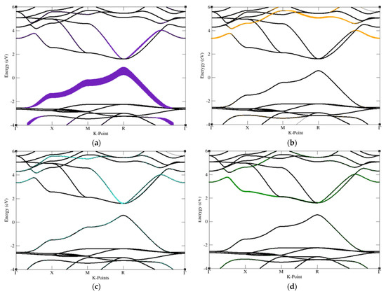
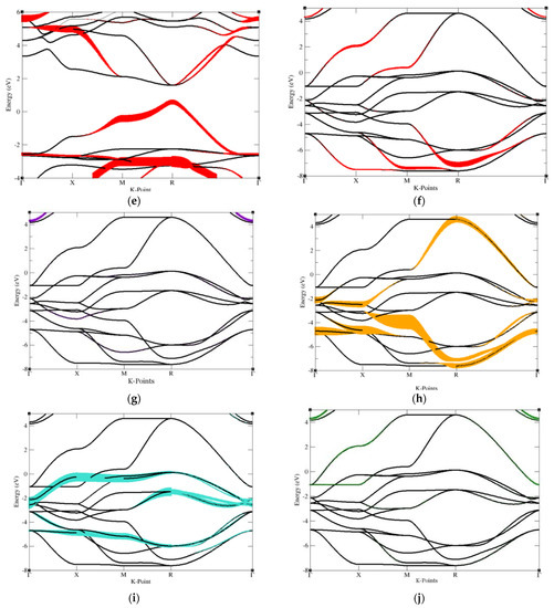
Figure 4.
Fat band of halide and oxide perovskite, the main contribution of each atom contained in cubic perovskite structure graphed out separately. These graphs are drawn for the purpose of sufficiently observing the main contribution of the atoms contained in the structure in order to adjust the energy bandgap. (a) Cs atom contained in CsSnCl3 (b) Sn atom contained in CsSnCl3, (c–e) Cl atom contained in CsSnCl3. (f) Sr atom of SrRhO3, (g) Rh atom of SrRhO3, (h–j) O atom of SrRhO3.
3.3. Mixed Perovskites
With a better understanding of the structural and electronic properties of halide and oxide perovskites, we next sought to design mixed perovskite compounds to achieve the optimal bandgap ranges of 1.0 to 1.7 eV [44] for photovoltaic cell applications. We studied the effects of combining two oxide and two halide perovskites in various configurations, while fixing the total number of atoms to 20 per supercell. We also computed the formation energies to obtain stability information on the mixed perovskite compounds. Table 4 displays the bandgap, corrected bandgap and formation energy of mixed perovskites.
Table 4.
Electronic bandgap for 2 × 2 × 1 mixed perovskites as well as formation energy.
3.3.1. Cs4Sn4Cl6I6
We hypothesized that mixing half of each of the halide perovskites would be the most efficient method of adjusting the bandgap to a desirable value, since both perovskites exhibit direct bandgaps and already possess bandgaps close to the optimal values. We tested mixing 50% of both halide perovskites, CsSnCl3 and CsSnI3, to form Cs4Sn4Cl6I6. The computational results showed an indirect bandgap on the Γ point at approximately 1.9 eV, which was not in the range of the optimal values. Still, the formation energy was about 0.023 eV, indicating that the mixed halide perovskite formed a relatively stable structure, and that fewer defects may form under different concentrations or temperatures.
3.3.2. Cs2Sn2Cl3I3Sr2TiRhO6
We next combined two halide (CsSnCl3, CsSnI3) and oxide (SrRhO3, SrTiO3) perovskites to form the mixed compound, Cs2Sn2Cl3I3Sr2TiRhO6. The bandgap was located right on the Γ point, with a value of approximately 1.2 eV. Since we used the GGA approximation, the experimental bandgap is likely to fall into the range of 1.0–1.7 eV. However, the formation energy was found to be 68.304 eV, indicating that under low concentrations or low temperature, defects may occur due to the structural instability of the compound. Such defects may also decrease the lifetime and efficiency of the semiconductor
3.3.3. Cs2Sn2Cl6Sr2Ti2O6
Furthermore, we combined two CsSnCl3 and two SrTiO3 perovskites to form Cs2Sn2Cl6Sr2Ti2O6, resulting in an indirect bandgap of 1.1 eV. We found that the VBM was located on the R point while the CBM was on the Γ point. Due to the GGA approximation, the bandgap is likely to be in the optimal ranges for photovoltaic applications. However, the formation energy was very high, similar to the mixed compound Cs2Sn2Cl3I3Sr2TiRhO6 above, indicating the likelihood of defects at different concentrations or temperatures. We also found less electrons occupying under the Fermi level, and more gathered around the conduction bands.
3.3.4. CsSnCl3Sr3Ti2RhO12
Lastly, CsSnCl3Sr3Ti2RhO12, consisted of CsSnCl3, SrRhO3 and SrTiO3, appeared to be an indirect bandgap through R-Γ in a value of 1.05 eV. According to the graph, VBM was located on the R point but CBM was on the Γ point. So the bandgap can barely reach the goal of 1.0 eV to 1.7 eV. The formation energy of the compound is rather low compared to previous combinations, which is 34.4. As the graph shows, the bands are likely to surround the Fermi level.
3.3.5. Implication
No previous literature has investigated or discussed perovskites mixtures. This paper exhibits a new method that demonstrates the possibility of retaining the stability and improving the efficiency of existing perovskites.
This paper also demonstrates the utility of adjusting bandgaps as a way of making unfit materials suitable for use. Finally, this paper explored the properties of mixed perovskites in hopes of contributing to their use in future applications.
4. Conclusions
In summary, we designed mixed perovskites to optimize bandgap and stability towards photovoltaic applications based on the understanding of the structural and electronic properties of halide-oxide perovskite compounds mixed in various configurations.
Upon stoichiometrically combining two different types of perovskites, all cubic perovskites generally exhibited dominant contributions on the CBM and VBM bands. The B-p and X-p states tended to be positioned at the top of the VBM and the bottom of the CBM respectively, producing B-x bonds in which the bonding intensity was dependent on the atomic radius. The hybridization between p-p bonds was generally weak. We next found that bandgaps could be readily adjusted via different configurations of unit cells. The compound Cs2Sn2Cl3I3Sr2TiRhO6 showed promise for photovoltaic applications, with bandgaps appearing at the Γ point and within the ideal ranges of 1.0–1.7 eV solar cell energy applications. The compound Cs4Sn4Cl6I6 possessed an indirect bandgap of 1.9 eV as can be seen in Figure 5.
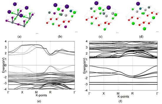
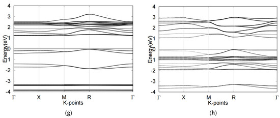
Figure 5.
Atomic structures of (a) Cs4Sn4Cl6I6 (b) Cs2Sn2Cl3I3Sr2TiRhO6 (c) Cs2Sn2Cl6Sr2Ti2O6 and (d) CsSnCl3Sr3Ti2RhO12 mixed perovskite compounds were displayed along with the labels of the atoms. Electronic band structure of compounds (e) Cs4Sn4Cl6I6 (f) Cs2Sn2Cl3I3Sr2TiRhO6 (g) Cs2Sn2Cl6Sr2Ti2O6 (h) CsSnCl3Sr3Ti2RhO12 were also presented with various bandgaps.
Negative formation energy value, according to the equation that we used to calculate it, indicates that the material is stable. Although Cs4Sn4Cl6I6 did not show a desirable bandgap value, its formation energy of 0.023 eV indicated high structural stability, further indicating advantages for use under harsh conditions. The two combinations can be applied under disparate conditions.
Theoretical calculations do provide insight into the probable real-world trends to be found in the manipulation of these materials. However, it must be remembered that this theoretical calculation does not consider real-life factors. As such, experimental trial data and results may not be equivalent to those of theoretical calculations, even as they remain similar.
Author Contributions
Conceptualization, X.L. and H.W.; methodology, H.W.; software, X.L.; validation, H.W.; formal analysis, H.W.; investigation, H.W.; resources, H.W.; data curation, X.L.; writing—original draft preparation, H.W.; writing—review and editing, X.L.; visualization, H.W.; supervision, X.L.; project administration, X.L.; funding acquisition, H.W. Both authors have read and agreed to the published version of the manuscript.
Funding
This research received no external funding.
Institutional Review Board Statement
Not applicable.
Informed Consent Statement
Not applicable.
Data Availability Statement
No new data were created or analyzed in this study. Data sharing is not applicable to this article.
Conflicts of Interest
The authors declare that they have no conflict of interest.
References
- McKenzie, H.; Wallace, H. The Kjeldahl determination of Nitrogen: A critical study of digestion conditions-Temperature, Catalyst, and Oxidizing agent. Aust. J. Chem. 1954, 7, 55–70. [Google Scholar] [CrossRef]
- Molina, A.; Shaddix, C.R. Ignition and devolatilization of pulverized bituminous coal par-ticles during oxygen/carbon di-oxide coal combustion. Proc. Combust. Inst. 2007, 31, 1905–1912. [Google Scholar] [CrossRef]
- Grätzel, M. Dye-sensitized solar cells. J. Photochem. Photobiol. C Photochem. Rev. 2003, 4, 145–153. [Google Scholar] [CrossRef]
- Trupke, T.; Green, M.; Wurfel, P. Improving solar cell efficiencies by down-conversion of high-energy photons. J. Appl. Phys. 2002, 92, 1668–1674. [Google Scholar] [CrossRef]
- Polman, A.; Knight, M.; Garnett, E.; Ehrler, B.; Sinke, W.C. Photovoltaic materials: Present efficiencies and future challenges. Science 2016, 352, aad4424. [Google Scholar] [CrossRef] [PubMed]
- Green, M.A. Solar Cells: Operating Principles, Technology, and System Applications; Prentice-Hall, Inc.: Englewood Cliffs, NJ, USA, 1982; p. 288. [Google Scholar]
- Attfield, J.P.; Lightfoot, P.; Morris, R. Perovskites. Dalton Trans. 2015, 44, 10541–10542. [Google Scholar] [CrossRef] [PubMed]
- Snaith, H.J. Perovskites: The Emergence of a New Era for Low-Cost, High-Efficiency Solar Cells. J. Phys. Chem. Lett. 2013, 4, 3623–3630. [Google Scholar] [CrossRef]
- Hodes, G. Perovskite-Based Solar Cells. Science 2013, 342, 317–318. [Google Scholar] [CrossRef] [PubMed]
- Chen, M.; Ju, M.-G.; Carl, A.; Zong, Y.; Grimm, R.L.; Gu, J.; Zeng, X.C.; Zhou, Y.; Padture, N.P. Cesium Titanium(IV) Bromide Thin Films Based Stable Lead-free Perovskite Solar Cells. Joule 2018, 2, 558–570. [Google Scholar] [CrossRef]
- Ju, M.-G.; Dai, J.; Ma, L.; Zeng, X.C. Lead-Free Mixed Tin and Germanium Perovskites for Photovoltaic Application. J. Am. Chem. Soc. 2017, 139, 8038–8043. [Google Scholar] [CrossRef]
- Stoumpos, C.C.; Malliakas, C.D.; Kanatzidis, M.G. Semiconductingtin and lead io-dide perovskites with organic cations: Phase transitions, high mobilities, and near-infrared photoluminescent properties. Inorg. Chem. 2013, 52, 9019–9038. [Google Scholar] [CrossRef]
- Wu, X.; Trinh, M.T.; Niesner, D.; Zhu, H.; Norman, Z.; Owen, J.; Yaffe, O.; Kudisch, B.; Zhu, X.-Y. Trap States in Lead Iodide Perovskites. J. Am. Chem. Soc. 2015, 137, 2089–2096. [Google Scholar] [CrossRef]
- Koliogiorgos, A.; Baskoutas, S.; Galanakis, I. Electronic and gap properties of lead-free per-fect and mixed hybrid halide per-ovskites: An ab-initio study. Comput. Mater. Sci. 2017, 138, 92–98. [Google Scholar] [CrossRef][Green Version]
- Arkan, F.; Izadyar, M. Computational modeling of the photovoltaic activities in EABX3 (EA = ethylammonium, B = Pb, Sn, Ge, X = Cl, Br, I) perovskite solar cells. Comput. Mater. Sci. 2018, 152, 324–330. [Google Scholar] [CrossRef]
- Ma, L.; Ju, M.G.; Dai, J.; Zeng, X.C. Tin and germanium based two-ruddlesden–popper hybrid perov-skites for potential lead-free photovoltaic and photoelectronic applications. Nanoscale 2018, 10, 11314–11319. [Google Scholar] [CrossRef] [PubMed]
- Lee, M.M.; Teuscher, J.; Miyasaka, T.; Murakami, T.N.; Snaith, H.J. Efficient hybrid solar cells based on meso-superstructured organometal halide perovskites. Science 2012, 338, 643–647. [Google Scholar] [CrossRef] [PubMed]
- Kojima, A.; Teshima, K.; Shirai, Y.; Miyasaka, T. Organometal halide perovskites as visible-light sensitizers for photovoltaic cells. J. Am. Chem. Soc. 2009, 131, 6050–6051. [Google Scholar] [CrossRef]
- Huang, Y.H.; Dass, R.I.; Xing, Z.L.; Goodenough, J.B. Double per-ovskites as anode materials for sol-id-oxide fuel cells. Science 2006, 312, 254–257. [Google Scholar] [CrossRef]
- Howard, C.J.; Kennedy, B.J.; Woodward, P.M. Ordered double perovskites—A group-theoretical analysis. Acta Cryst. Graph. Sect. B Struct. Sci. 2003, 59, 463–471. [Google Scholar] [CrossRef]
- Liang, K.C.; Du, Y.; Nowick, A.S. Fast high-temperature proton transport in nonsto-ichiometric mixed perovskites. Solid State Ion. 1994, 69, 117–120. [Google Scholar] [CrossRef]
- Bi, D.; Tress, W.; Ibrahim Dar, M.; Gao, P.; Luo, J.; Renevier, C.; Schenk, K.; Abate, A.; Giordano, F.; Correa Baena, J.P.; et al. Efficient luminescent solar cells based on tailored mixed-cation perovskites. Sci. Adv. 2016, 2, e1501170. [Google Scholar] [CrossRef]
- Abate, A. Perovskite Solar Cells Go Lead Free. Joule 2017, 1, 659–664. [Google Scholar] [CrossRef]
- Yang, E.; Xuan Luo, X. Theoretical pressure-tuning bandgaps of double perovskites a2 (bb) x6 for photovoltaics. Sol. Energy 2020, 207, 165–172. [Google Scholar] [CrossRef]
- Alharbi, E.A.; Alyamani, A.Y.; Kubicki, D.J.; Uhl, A.R.; Walder, B.J.; Alanazi, A.Q.; Luo, J.; Burgos-Caminal, A.; Albadri, A.; Albrithen, H.; et al. Atomic-level passivation mechanism of ammonium salts enabling highly efficient perovskite solar cells. Nat. Commun. 2019, 10, 3008. [Google Scholar] [CrossRef]
- Wang, X.; Ling, Y.; Lian, X.; Xin, Y.; Dhungana, K.B.; Perez-Orive, F.; Knox, J.; Chen, Z.; Zhou, Y.; Beery, D.; et al. Suppressed phase separation of mixed-halide perovskites confined in endotaxial matrices. Nat. Commun. 2019, 10, 695. [Google Scholar] [CrossRef]
- Zhu, C.; Niu, X.; Fu, Y.; Li, N.; Hu, C.; Chen, Y.; He, X.; Na, G.; Liu, P.; Zai, H.; et al. Strain engineering in perovskite solar cells and its impacts on carrier dynamics. Nat. Commun. 2019, 10, 815. [Google Scholar] [CrossRef] [PubMed]
- Lang, L.; Yang, J.H.; Liu, H.R.; Xiang, H.J.; Gong, X.G. First-principles study on the electronic and optical properties of cubic abx3 halide perovskites. Phys. Lett. A 2014, 378, 290–293. [Google Scholar] [CrossRef]
- Shum, K.; Chen, Z.; Qureshi, J.; Yu, C.; Wang, J.J.; Pfenninger, W.; Vockic, N.; Midgley, J.; Kenney, J.T. Synthesis and char-acterization of CsSnI3 thin films. Appl. Phys. Lett. 2010, 96, 221903. [Google Scholar] [CrossRef]
- Sun, P.P.; Li, Q.S.; Feng, S.; Li, Z.S. Mixed ge/pb perovskite light absorbers with an ascendant efficiency explored from the-oretical view. Phys. Chem. Chem. Phys. 2016, 18, 14408–14418. [Google Scholar] [CrossRef] [PubMed]
- Mosconi, E.; Umari, P.; De Angelis, F. Electronic and optical properties of mixed sn–pb or-ganohalide per-ovskites: A first principles investigation. J. Mater. Chem. A 2015, 3, 9208–9215. [Google Scholar] [CrossRef]
- Hong, F.; Saparov, B.; Meng, W.; Xiao, Z.; Mitzi, D.B.; Yan, Y. Viability of lead-free perov-skites with mixed chalcogen and halogen anions for photovoltaic applications. J. Phys. Chem. C 2016, 120, 6435–6441. [Google Scholar] [CrossRef]
- Borriello, I.; Cantele, G.; Ninno, D. Ab initio investigation of hybrid organic-inorganic perovskites based on tin halides. Phys. Rev. B 2008, 77, 235214. [Google Scholar] [CrossRef]
- Gonze, X.; Rignanese, G.M.; Verstraete, M.; Beuken, J.M.; Pouillon, Y.; Caracas, R.; Jollet, F.; Torrent, M.; Zerah, G.; Mikami, M.; et al. A brief introduction to the abinit software package. Z. Kristallogr. 2005, 220, 558–562. [Google Scholar] [CrossRef]
- Gonze, X.; Amadon, B.; Anglade, P.M.; Beuken, J.M.; Bottin, F.; Boulanger, P.; Bruneval, F.; Caliste, D.; Caracas, R.; Cote, M.; et al. Abinit: First principles approach of materials and nanosystem properties. Comput. Phys. Commun. 2009, 180, 2582–2615. [Google Scholar] [CrossRef]
- Perdew, J.P.; Burke, K.; Ernzerhof, M. Generalized gradient approximation made simple. Phys. Rev. Lett. 1996, 77, 3865–3868. [Google Scholar] [CrossRef] [PubMed]
- Blochl, P.E. Projector augmented-wave method. Phys. Rev. B 1994, 50, 17953–17979. [Google Scholar] [CrossRef]
- Holzwarth, N.A.W.; Tackett, A.R.; Matthews, G.E. A projector augmented wave (paw) code for electronic structure calculations, part i: Atompaw for generating atom-centered functions. Comput. Phys. Commun. 2001, 135, 329–347. [Google Scholar] [CrossRef]
- Tackett, A.R.; Holzwarth, N.; Matthews, G. A Projector Augmented Wave (PAW) code for electronic structure calculations, Part II: Pwpaw for periodic solids in a plane wave basis. Comput. Phys. Commun. 2001, 135, 348–376. [Google Scholar] [CrossRef]
- Morales-García, Á.; Valero, R.; Illas, F. An Empirical, yet Practical Way to Predict the Band Gap in Solids by Using Density Functional Band Structure Calculations. J. Phys. Chem. C 2017, 121, 18862–18866. [Google Scholar] [CrossRef]
- Cuneyt, S. Spin dynamics of complex oxides, bismuth-antimony alloys, and bismuth chalco-genides. arXiv 2015, arXiv:1511.05276. [Google Scholar]
- Deb, A.P.; Kumar, V. Ab initio design of cssn (xxy 1- x) 3 (x and y= cl, br, and i) perovskites for photovoltaics. AIP Adv. 2015, 5, 77158. [Google Scholar] [CrossRef]
- Daga, A.; Sharma, S.; Sharma, K.S. First Principle Study of Cubic SrMO3 Perovskites (M = Ti, Zr, Mo, Rh, Ru). J. Mod. Phys. 2011, 2, 812–816. [Google Scholar] [CrossRef]
- Liu, X.; Sohlberg, K. Theoretical calculations on layered perovskites: Implications for photocatalysis. Complex Met. 2014, 1, 103–121. [Google Scholar] [CrossRef]


Publisher’s Note: MDPI stays neutral with regard to jurisdictional claims in published maps and institutional affiliations. |
© 2021 by the authors. Licensee MDPI, Basel, Switzerland. This article is an open access article distributed under the terms and conditions of the Creative Commons Attribution (CC BY) license (https://creativecommons.org/licenses/by/4.0/).