Abstract
Designing advanced methods of corrosion protection and increasing the bearing capacity of pile foundations on saline clayey soils is a priority geotechnical task in Kazakhstan. The formation of a suffusion-resistant waterproof shell was achieved by silicatization of a borehole before concreting, by the installation of a mold into the borehole and the impregnation of a sodium silicate solution into the space between the mold and the soil under pressure. After coagulation of the silicate solution, the mold was removed and the formed shell was filled with corrosion-resistant concrete. Full-scale static pile load tests were conducted in the construction site “Retaining wall on Mount Koktobe” in Almaty. The bearing capacity of the piles with the protective silicate shell exceeded the bearing capacity of an ordinary pile by 2.5 times on average without wetting the site, and 3.2 times after prolonged wetting. The numerical model had a close relationship with the average experimental curve obtained when conducting six static pile load tests with the protective shell. A large economic effect of the developed piling technology with a protective shell was achieved, with a significant reduction in the cost of piling, equal to 27.85%.
1. Introduction
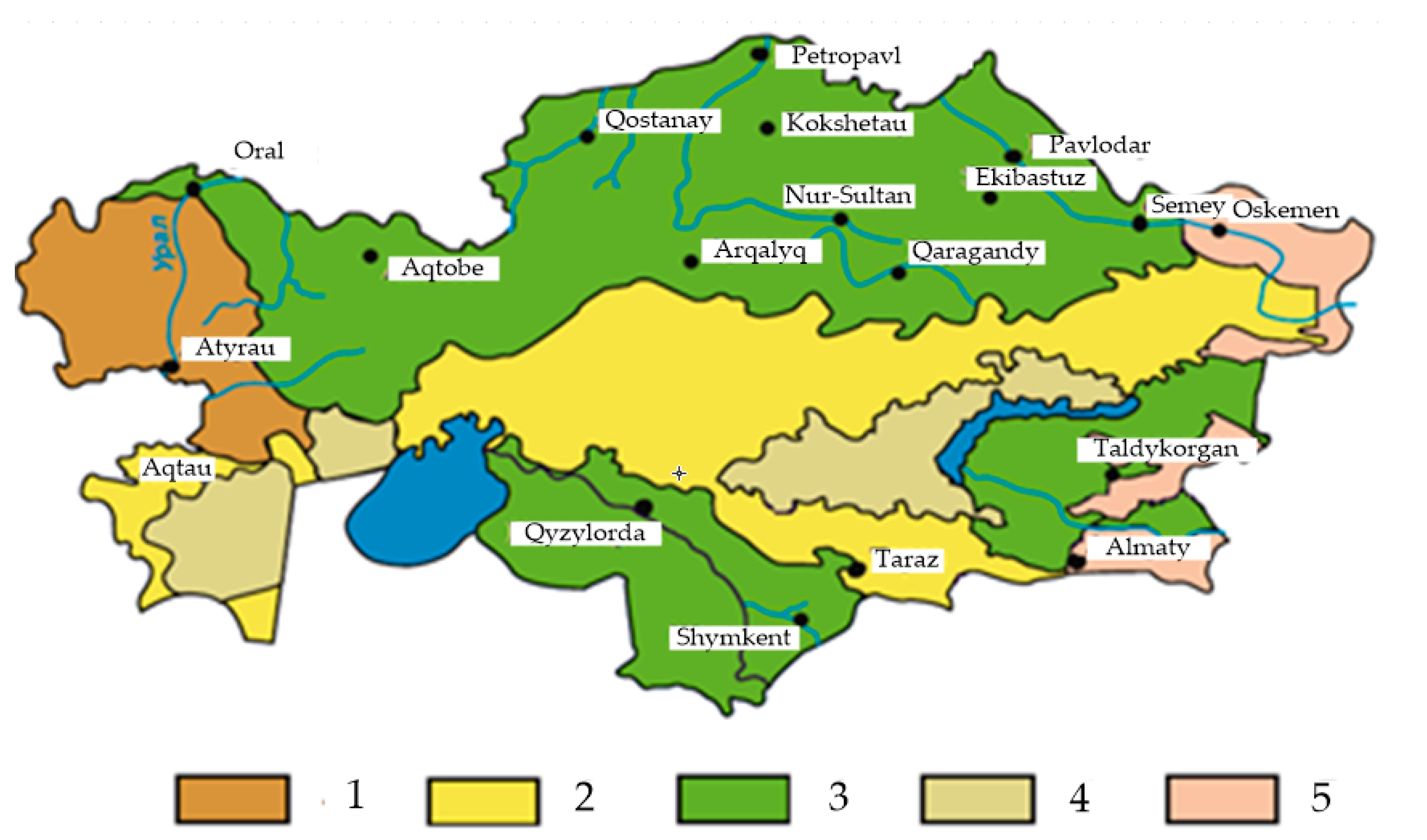
In Central Asia, particularly Kazakhstan, almost a third of all areas are formed on saline silty-clayey soils (Figure 1). Salts in the soils of arid regions are compiled due to the following factors: hot air, penetrating into cracks and pores; an aggressive water–salt soil medium, causing intensive evaporation of the solutions contained in them. Salts that precipitate from the solution in the form of crystalline inclusions fill the pore space of clay soils. The concentration of salts in the solid phase has been observed in the aeration zone to a depth of 3 to 5 m [1].
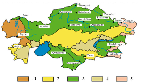
Figure 1.
Map of saline soils of Kazakhstan according to NTP RK 07-01.1-2011 [2]: (1) chloride and sulfate-chloride; (2) sulfate; (3) sulfate and chloride-sulfate; (4) gypsum salinization; (5) insignificant salinity soils.
The construction of buildings and structures on saline silty-clayey soils in accordance with the regulations NTP RK 07-01.1-2011 “Design of buildings on salt soils” [2] is associated with an increase in material and labor costs by 5–25% when compared with construction on nonsaline soils. Despite the enormous additional costs, the experience of their operation indicates that many facilities undergo uneven collapsing settlements, exceeding the designed ones by 1.5–3 times and more (NTP RK 07-01.1-2011, 2011) [2]. According to the All-Russian Research Institute of Hydraulic Engineering named after B.Ye. Vedenev, in 350 out of 960 surveyed irrigation and drainage and hydraulic structures on the saline clayey soils in the republics of Central Asia and Kazakhstan, excess settlements were observed. Soil stabilization methods used in Kazakhstan include soil treatment with cement mortars and silicate solutions, thermal and electrochemical methods, and strengthening with clay soils for noncohesive soils [3]. However, corrosion and, consequently, a gradual decrease in the bearing capacity of concrete structures in a chemically aggressive soil environment also have great impacts on subsequent operation.
Corrosion-resistant materials for the surface protection of concrete structures, according to review studies of Pan et al., 2017 [4] and Brito and Kurda, 2021 [5], in terms of the mechanism of action, can be divided into four groups: surface coating, surface treatments, pore-blocking surface treatment, and hydrophobic impregnation. In terms of corrosion-resistant materials, they are subdivided to organic and inorganic based. The organic protection of a concrete pile by oil-bituminous rocks or natural bitumen is an efficient but labor-intensive and a short-service-life method [6,7]. A number of scientists have presented surface coatings with inorganic materials: acrylic [8], polyurethane [9], polymer nanocomposite as a polymer-clay [10], polymer-silica [11], and epoxy resins [12].
Hydrophobic impregnation, preventing the penetration of aggressive liquid through the pores of concrete, was implemented by incorporating nanoparticles [13,14], micro silica [15], or stearic acid emulsion [16]. Increased hydrophobic coatings were also achieved by including ammonium polyphosphate [17], calcium carbonate nanoparticles [18], candle soot [19,20], cyanoacrylates [21], and rise husk ash [22].
The strategies of pore-blocking concrete surface treatment with fluosilicate [23], sodium silicate [24], and calcium silicate-based solutions [25] are some of the types of surface treatment of reinforced concrete structures. However, it should be noted that the high friction of soil particles increases the risk of surface abrasion, and the inability to control the integrity of the protective coating during the operation of the foundations complicate the technology of their application in deep foundations.
As for the ground improvement, the samples treated with silicate cement [26], geopolymers [27], and fly ash and slag [28] have shown reliable results in terms of collapsible deformations under loading in wetting conditions and soil stabilization in general. Thus, based on the experience of previous research, including personal contributions of the authors in this area [29], it was required to develop a progressive corrosion protection method that meets the design requirements of an aggressive saline soil environment satisfying SP RK 2.01-101-2013 [30] and, at the same time, increasing the bearing capacity and durability of bored pile foundations:
- -
- Formation of a protective corrosion-resistant “shell” around the pile;
- -
- Formation of a compacted or ground-improved soil layer around the pile by increasing its strength and deformation properties, structural and suffusion resistance, and water resistance and waterproofness;
- -
- Increasing the strength and corrosion resistance of the concrete of the structure by using modifiers, etc.
2. Materials and Methods
2.1. Design of the Protective Case
The formation of a suffusion-resistant waterproof layer of soil with increased strength under the tip and along the lateral surface of the pile when installing a bored pile was achieved by silicatization of the borehole during the installation (Figure 2 and Figure 3). For this, a borehole was pre-drilled in saline silty-clayey soils to the required depth from which excess soil was extracted. The inner walls of the borehole were impregnated with a low-concentration sodium silicate solution. The chemical interaction of sodium silicate with carbonates and gypsum contained in saline silty-clayey soils leads to the formation of a viscous silicic acid hydrogel film, which cures on particles and soil aggregates and tightly clogs capillaries and pores. The formation of a silicic acid gel was confirmed by fluoroscopy and microscopy.
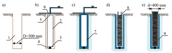
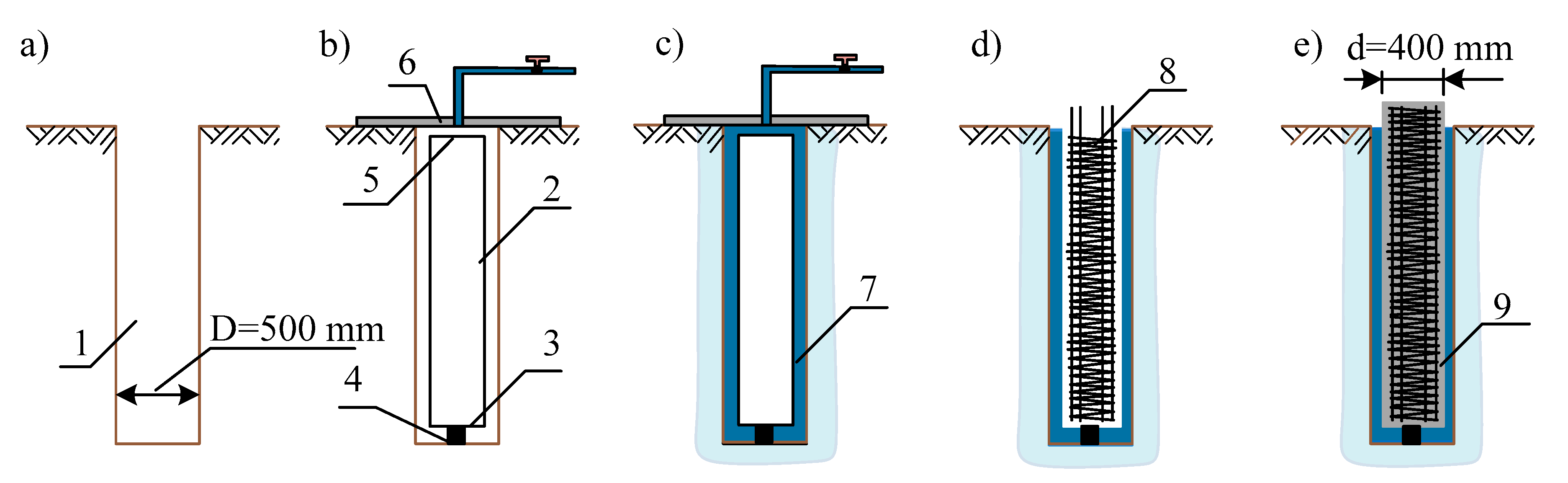
Figure 2.
Installation of short-length bored piles in saline soils in a protective and load-bearing casted case: (a) borehole; (b) placement of the inner tube in the borehole; (c) impregnation of walls and bottom side with silicate solution; (d) reinforcement; (e) concreting. 1—borehole; 2—steel tube with bottom flange; 3,4—position fixing; 5—top flange; 6—disk seal with solution supply pipeline; 7—protective shell; 8—reinforcement; 9—concrete.

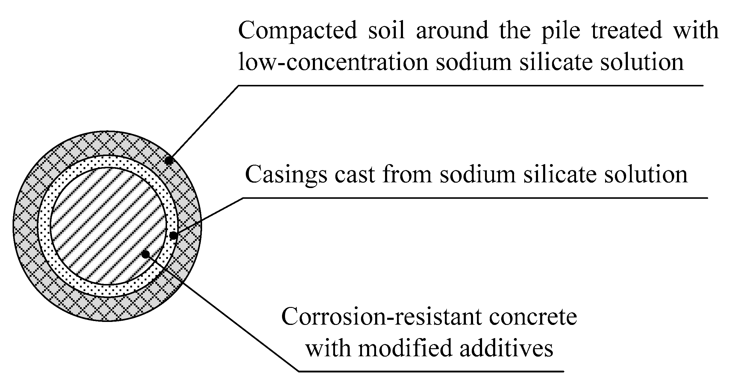
Figure 3.
Design of the protective case.
Saline silty-clayey soils contain up to 15–30% or more salt inclusions in the form of carbonic acid and sulfuric acid calcium, magnesium, etc. The chemical process of treating the clayey soils around the pile is based on the good penetration of silicate solution into silty clay and on the rapid release of the cementing soil silicic acid gel films due to the reaction of a sodium silicate solution with soil salts [31]:
Na2O·nSiO2 + CaSO4 + mH2O → nSiO2 (m − 1)H2O + Ca(OH)2 + Na2SO4
The coagulation of a silicate solution in contact with salt waste was confirmed by laboratory testing on the interaction with pure salts (CaCO3, CaSO4·2H2O, etc.) and led to the following conclusions:
- -
- The rate of coagulation of silicate solutions and the formation of SiO₂ gel films on salts depend on three factors: the concentration of the sodium silicate solution, and the amount and quality of salts present in the salt waste. Film formation during the interaction of a sodium silicate solution with calcium sulfate slows down with an increase in the concentration of the silicate solution, which is explained by a decrease in the solubility of the reacting salt with the increase in the concentration of silicate. The film thicknesses when using sodium silicate of 10%, 20%, and 30% concentrations were, respectively, 40, 20, and 10 microns.
- -
- With regard to the coagulation of silicate solutions in the soil, the sulfuric acid salts of Ca+2; and Mg+2 are of the greatest importance as the most soluble compounds, in comparison with carbon dioxide Ca, which is almost inert.
In addition to the formation of a gel of silicic acid and lime hydrate, exchange reactions occurred in the absorbing complex of the salt waste, and as a result, secondary products formed in an alkaline medium. Therefore, the strength of the fixed salt waste largely depends on the value of the absorption capacity of the salt waste in the natural state, which is expressed in mmol per 100 g of dry salt waste, in an alkaline solution.
In the course of interaction within the porous media, a silicic acid gel film formed on the soil particles and capillary walls. Pores and capillaries in the nearby soil became clogged and impermeable. As the solution was injected, the thickness of the protective casing increased and the strength of the soil rose. The transition of the solution into the gel proceeded during the first 3 days, and the hardening of the gel and, accordingly, the soil mass around the pile proceeded during the next 15 days and ended after 28 days (R = 1.1–1.8 MPa).
Then, the borehole was filled with corrosion-resistant concrete, which was achieved through modified additives that also increased the density of the concrete. Further curing of the casted concrete pile took place in a structurally and suffusion-resistant shell with increased strength, water resistance, and waterproofness. The total diameter of a bored pile casted in a protective load-bearing shell including a silicate-fixed soil layer around the pile was about 600–700 mm.
2.2. Field Tests
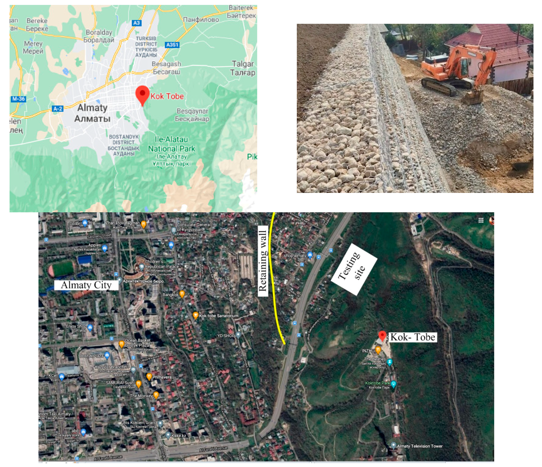
Field tests were carried out on saline silty-clayey soils with a content of readily soluble salts up to 3% and carbonates up to 27% for the object: “Retaining wall on Mount Koktobe in Almaty” (Figure 4). According to the data of engineering-geological surveys carried out at the site with soil sampling to a depth of 20 m, the geological structure of the site’s soils is represented by silty clays interlayered with clayey soils. The content of carbonates in loams is up to 27%, and easily and medium-soluble salts up to 3%. The topsoil layer is 0.3 m. The degree of aggressiveness of soils in relation to the impact on reinforced concrete structures varies from average on Portland cements to strong on sulfate-resistant brands of cement. The physical and mechanical properties of saline silty-clayey soils of the base of the test site are shown in Table 1.
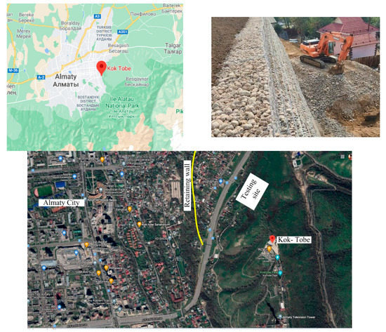
Figure 4.
Construction site “Retaining wall on Mount Koktobe” in Almaty.

Table 1.
Physical and mechanical properties of saline silty-clayey soils test site.
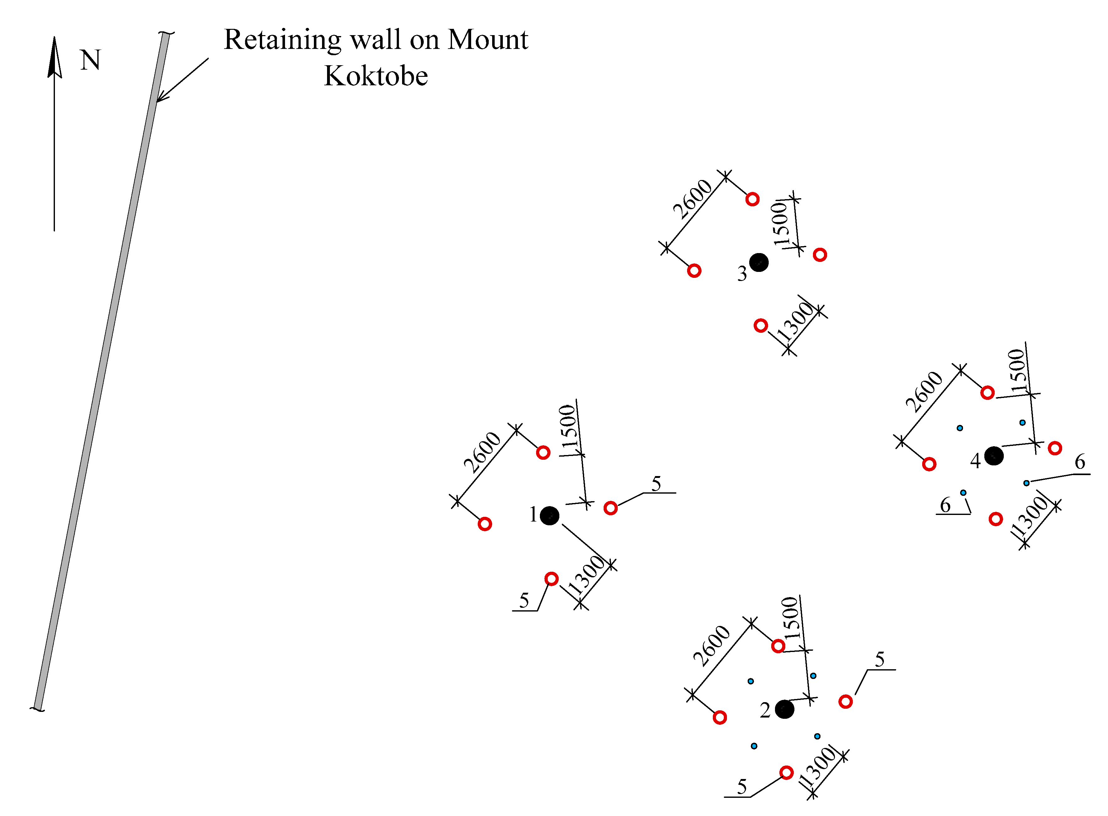
To study the effect of the desalinization processes on the bearing capacity of the piles, it was decided to install a friction pile with prolonged wetting, as well as a control pile without wetting. To determine the real behavior of the “pile-shell-soil” system, static load tests were carried out with piles in a protective and load-bearing shell for vertical indentation load: in the natural state and during leaching under flooding conditions. Six testing zones were observed during the installation of bored friction piles with a diameter of 400 mm and a length of 4 m. The allocation of the tested piles in each of the sections is presented in Figure 5. For a comparative analysis of the bearing capacity, near each experimental pile in the soil shell treated with silica solution (hereinafter referred to as “protective shell”), ordinary bored piles without a protective shell (hereinafter referred to as “ordinary pile”) were casted.

Figure 5.
Location of experimental piles at the construction site “Retaining wall on Mount Koktobe in Almaty.” 1—ordinary bored piles without soil wetting; 2—ordinary bored piles, with soil wetting; 3—cast-in situ concrete pile in the protective shell, without soil wetting; 4—cast-in situ concrete pile in the protective shell, with soil wetting; 5—anchor piles; 6—drainage tube.
Thus, the tests were carried out for:
- -
- Six bored piles with a protective shell, without soil wetting;
- -
- Six ordinary bored piles, without soil wetting;
- -
- Six bored piles with a protective shell, after wetting the soil;
- -
- Six ordinary bored piles, after wetting the soil.
Wetting of the soil mass around the pile continued for six months by pumping water into special drainage wells, 0.2 m in diameter, 3.5 m long, located at a distance of 1 m from the edge of the experimental pile (Figure 5). At the end of the wetting, significant desalinization was achieved near the pile soil massif as a result of suffusion processes and the partial migration of clay particles into the holes of the drainage tubes.
2.3. Site Testing Procedure
Static load tests of bored piles were carried out according to GOST 5686-2012 “Field test methods for piles” [32] to determine the settlement and bearing capacity of ordinary piles and piles with a protective shell. For testing the piles with static vertical-indentation loads, an anchor-stop stand was used, consisting of systems of main and auxiliary beams, four anchor piles, and anchor ties (clamps).
During the static piles load testing, the following equipment was used:
- -
- Hydraulic jack of the SMZh-158A brand with a lifting capacity of 2000 kN;
- -
- Manual pumping station MNSR-400 with pressure gauge MTP-160, with a capacity of 785 MPa;
- -
- Two deflection indicators 6PAO (for determining the settlement of the pile).
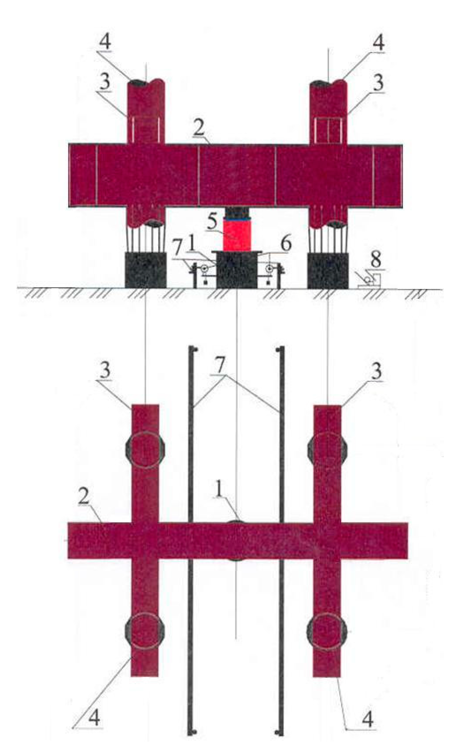
Reactive forces from the step loading of the pile by the jack were perceived by an anchor-stop stand, consisting of four anchor bored piles resisting the tension forces and a stop structure of metal beams (Figure 6).
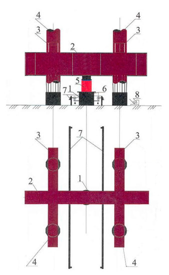
Figure 6.
Scheme of the anchor-stop stand for the static load test. 1—tested pile with protective and bearing shell; 2—main I-beam No.70; 3—secondary beams No.40; 4—anchor piles (steel pipes); 5—jack SMZh-158A (lifting capacity of 2000 kN); 6—6PAO deflection indicator; 7—reference system; 8—manual pumping station HCP-40 with pressure gauge MTP-160.
Static load tests were carried out by maintained load with the following sequence:
- -
- The piles were maintained for 7–10 days from the moment of their installation (until the concrete of the pile reached more than 80% of the design strength);
- -
- Loading of the pile was implemented by a vertical-compressing multiple-increasing load and held constant until the rate of settlement fell below 0.1 mm per hour;
- -
- Pile settlement was recorded using electrical displacement transducers according to the standard;
- -
- Unloading of the tested piles was carried out in steps equal to double loading steps;
- -
- Readings of the elastic deformation of the soil and concrete pile during unloading were registered at each stage every 15 min.
3. Results
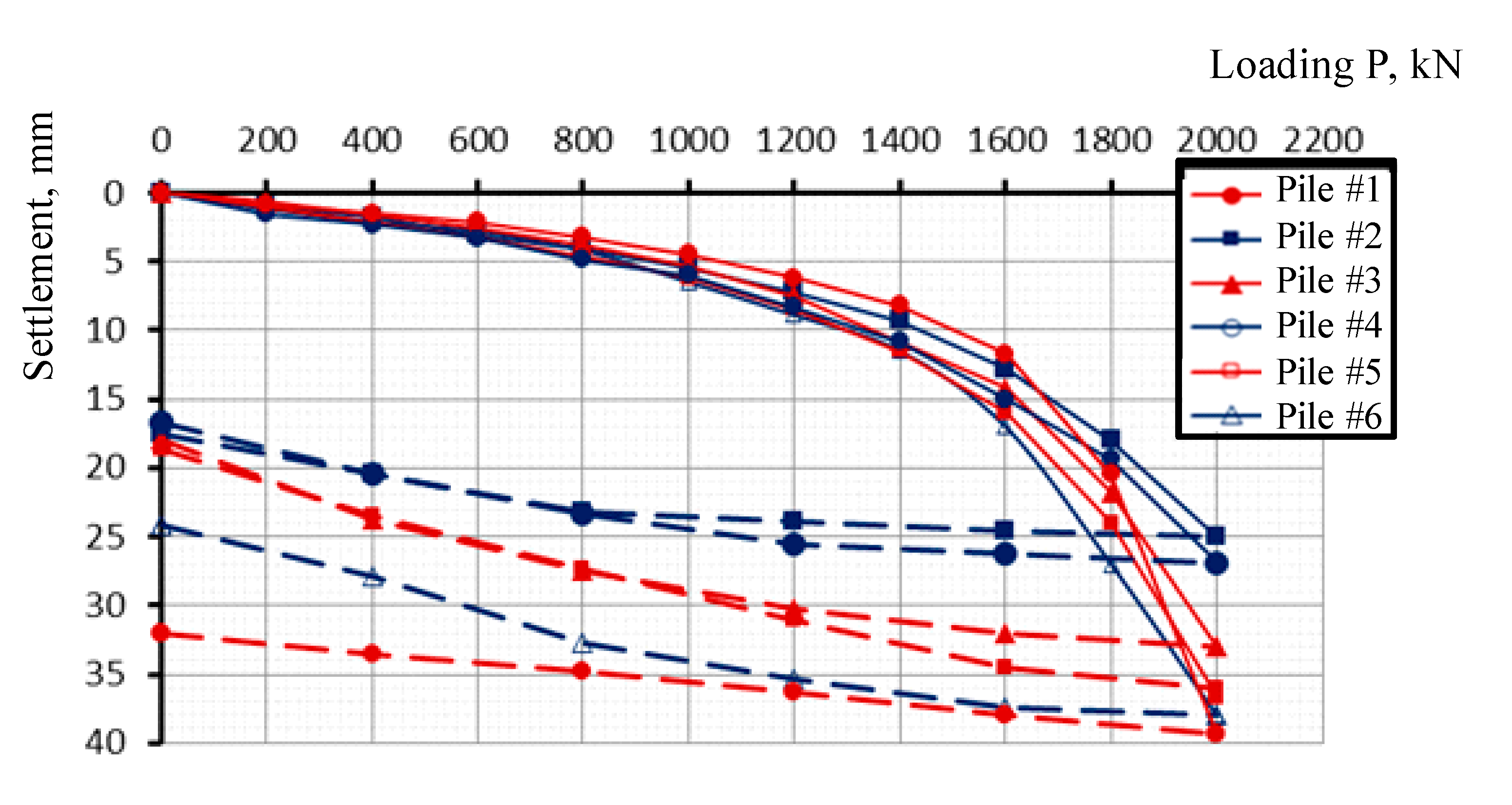
From the SLT results, the curves between the settlement ratio and load (s/P), where s is the settlement and P is the applied load for all types of piles in the six testing zones, are presented in Figure 7, Figure 8, Figure 9 and Figure 10. Thus, the tested piles in a protective shell, which are casted in a preliminary treated with sodium silicate solution soil, are presented in Figure 7. Here, pile #1 is a pile tested in zone 1, pile #2 in zone 2, and so on.
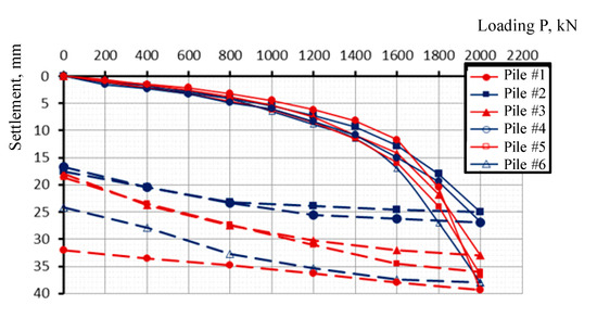
Figure 7.
Curve of the correlation of loading P with settlement S according to the results of static tests of piles with a protective shell (without soil wetting).

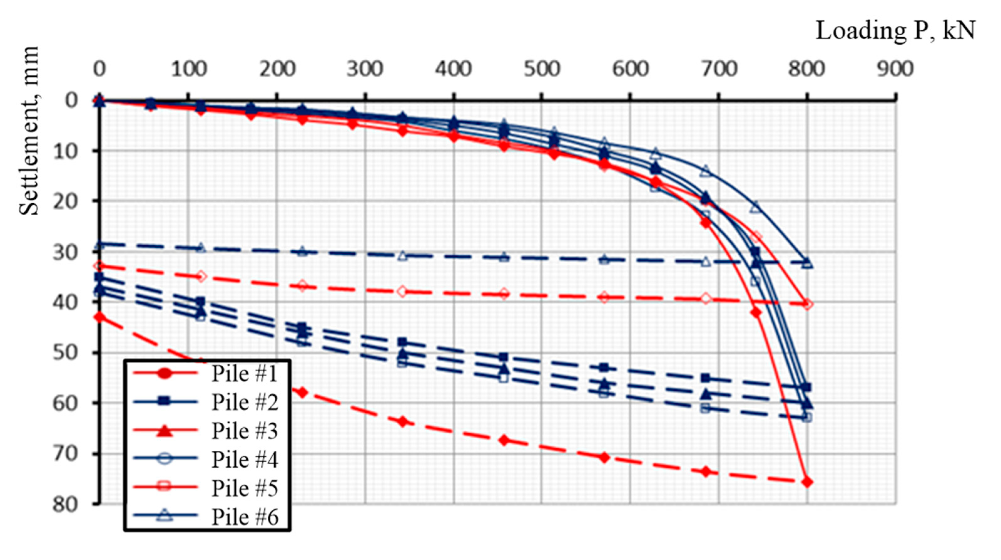
Figure 8.
Correlation of loading P with settlement S according to the SLT results of the ordinary piles (without soil wetting).

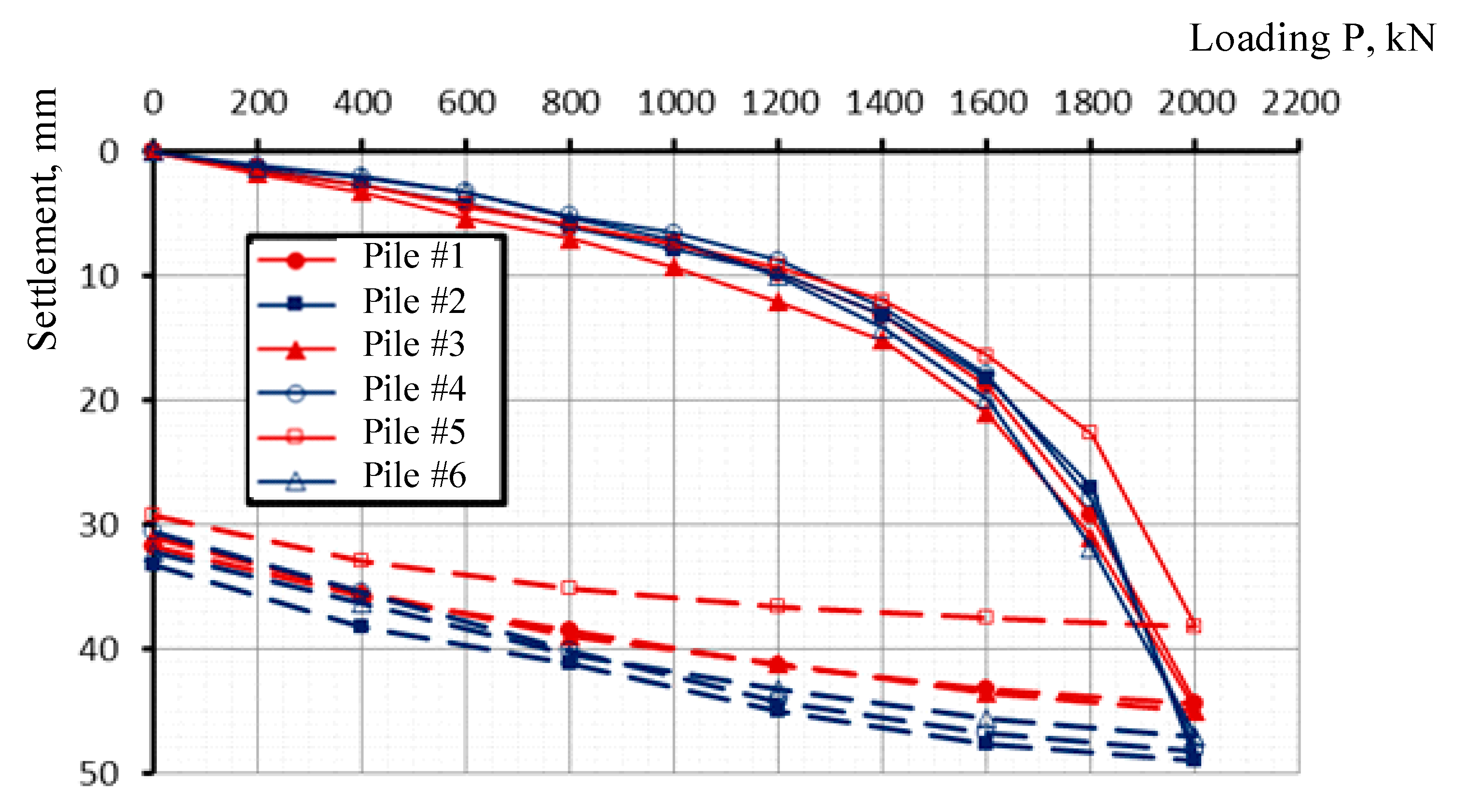
Figure 9.
Correlation of loading P with settlement S according to the SLT results of the piles with a protective shell (with soil wetting).
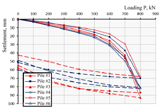
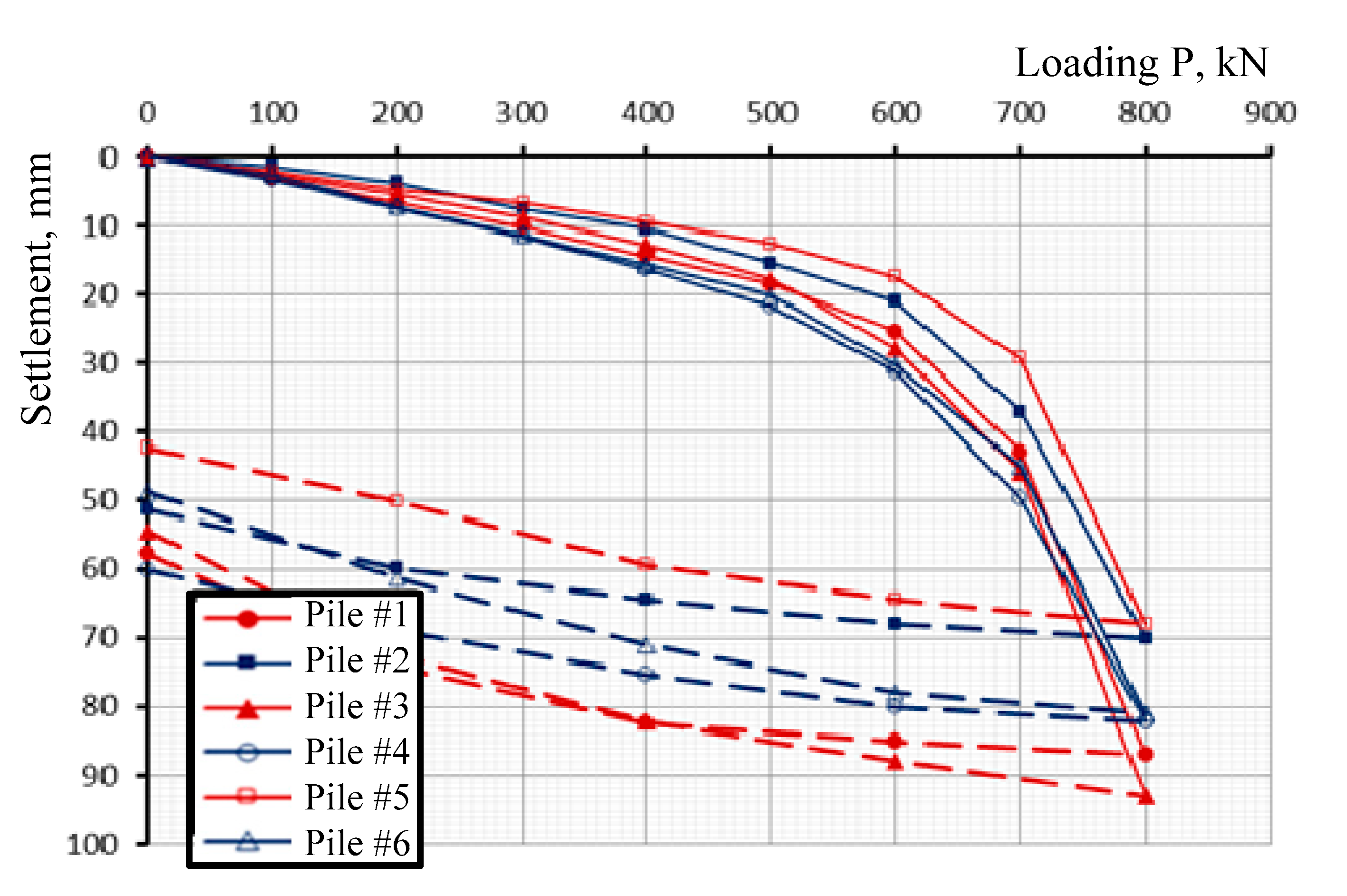
Figure 10.
Correlation of loading P with settlement S according to the SLT results of the ordinary piles (with soil wetting).
The values specified in the Standard p.p. 5.3–5.5 SP RK 5.01–103–2013 “Pile foundations” (2013) were taken as the criterion for the maximum permissible settlement. By the particular value of the limiting resistance of the pile to the compression load, Fu was understood as the load under which the reaction of the test pile takes a settlement equal to S, determined by the formula:
where Su,mt is the limiting value of the average settlement of the foundation of the designed structures, where industrial and civil one-storey and multi-storey buildings with a full frame is taken as equal to 8 cm (for reinforced concrete structures) according to the instructions of SP RK 5.01-103-2013 Pile foundations [33]. ζ is the coefficient of transition from the limiting value of the average settlement of the foundation of structures Su,mt to the settlement of the pile, obtained during static load tests with conditional stabilization (attenuation) of the settlement, taken as equal to 0.2 according to the instructions of SP RK 5.01-103-2013 “Pile foundations” [33].
S = ζSu,mt
The maximum permissible settlement is accepted to be 16 mm. The particular values of the experimental bearing capacities of the piles corresponding to the maximum permissible settlement are presented in Table 2.
Table 2.
Bearing capacity of piles according to the results of static pile load tests (SLT) and the results of statistical processing.
The results of the statistical check satisfy the condition |Fn − Fi| > vS; therefore, all the obtained results of the carrying capacities can be considered valid and suitable for further analysis.
Analysis of the influence of suffusion processes on the strength characteristics of soils was carried out for both types of pile loadings (Table 3 and Table 4). A comparison was made between the bearing capacity of piles with the protective shell and the bearing capacity of ordinary piles after prolonged wetting. The functional linear dependence to is expressed by the k coefficient.
where is the bearing capacity of piles according to the SLT without soil wetting, kN; and is the bearing capacity of piles after prolonged wetting of soils, kN.
Table 3.
Results of calculating the functional dependence for piles with protective shell.
Table 4.
Results of calculating the functional dependence for ordinary bored piles.
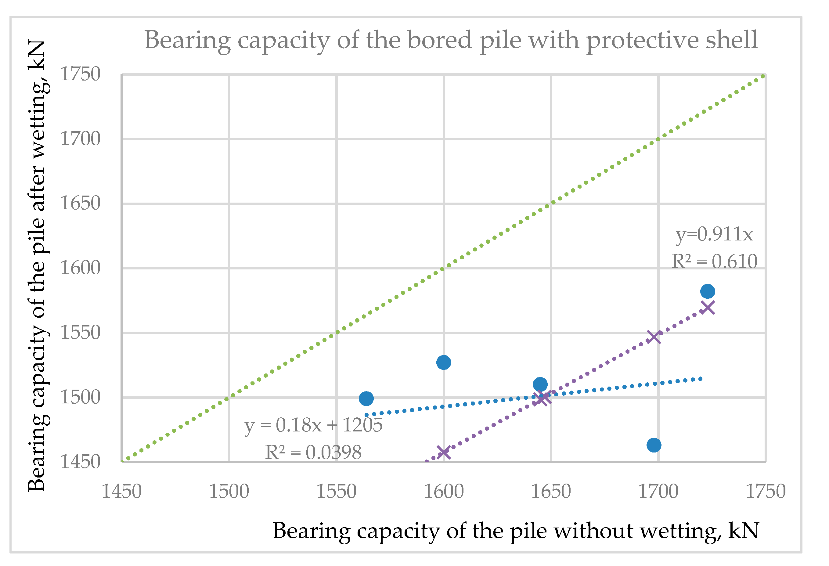
The relationship between the bearing capacity of piles without and after wetting for piles with the protective shell and for ordinary pile is presented in Figure 10 and Figure 11. Regression analysis of the functional dependence was performed using the least squares method. The bearing capacities were obtained from the coordinates of points on the plane, after which the line of best fit was drawn characterizing the proportional relationship, which deviated least of all from these points.
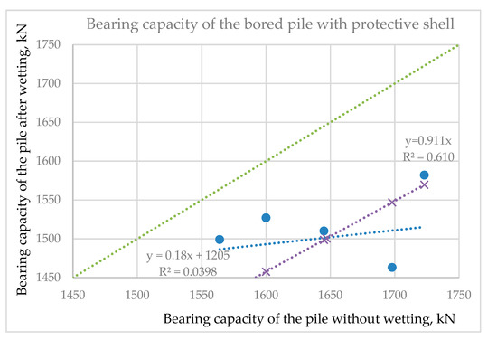
Figure 11.
Comparative diagram of the bearing capacity of piles with protective shell, after and without wetting.
To find the linear equation of the best-fit line using the least squares method, the coordinates of the points and were drawn until they intersected with the desired straight line (Figure 10 and Figure 11). The values of these ordinates are equal to (. The ordinate distance from the point to the straight line is (. Thus, the regression is expressed by the following equation:
It is assumed that the best-fit line would be the smallest value of the sum of the squares of all distances. The minimum of this sum was found according to the rules of differential calculus. To determine k and b, the following equations were obtained:
If we consider that the line passes through the origin, then the linear regression is:
To find the minimum of the equation, the partial values of its derivatives are equated to zero and a system of linear equations is obtained:
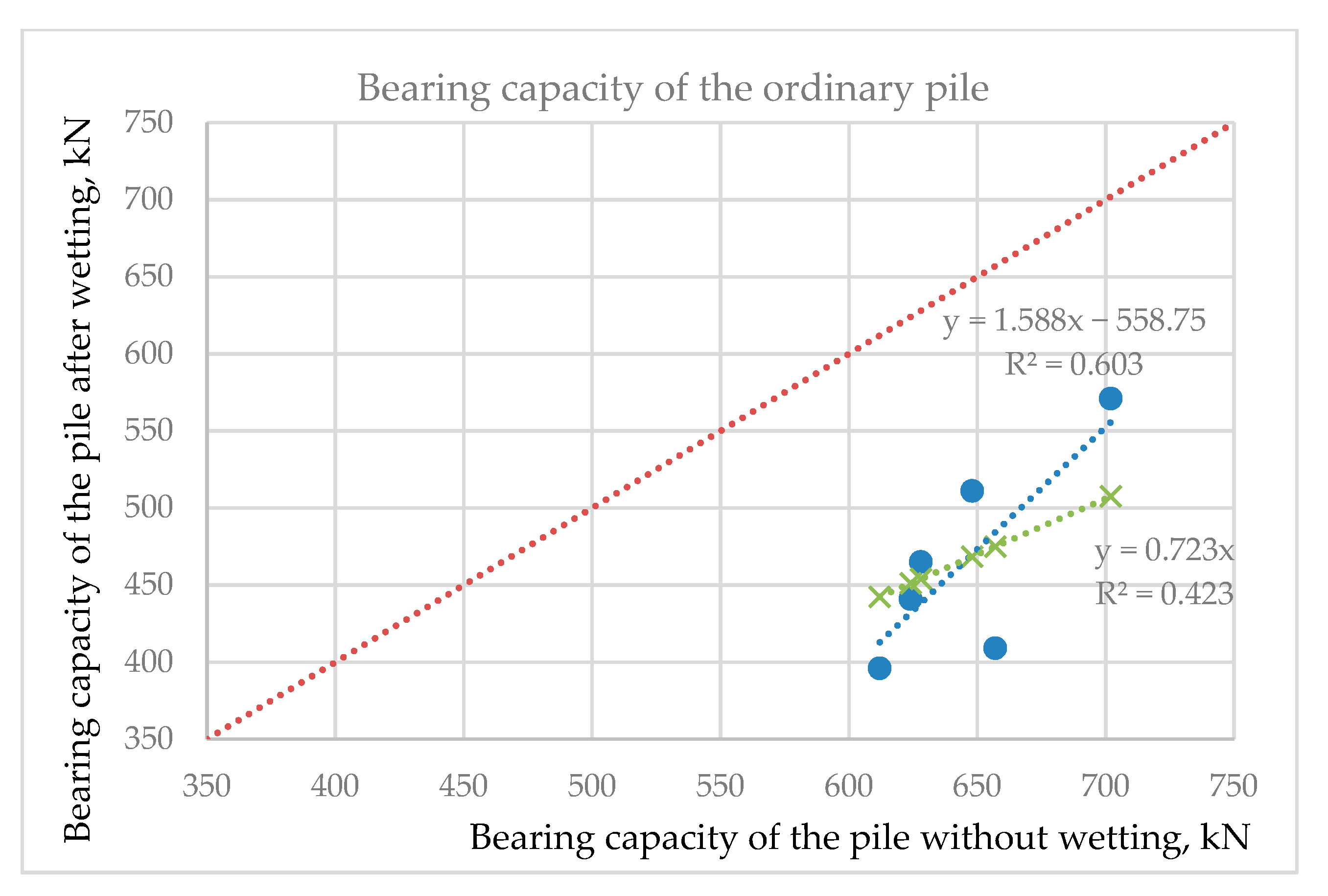
The results of bearing capacity of the piles by SLT are represented by blue dots in Figure 11 and Figure 12. The values obtained according to , where kx is equal to 0.911 and 0.723, respectively, are represented by crosses. The trend lines and corresponding formulas are also presented. As can be seen from the comparative diagram, all points are located below the diagonal, which indicates that all the values of the bearing capacities of the piles after wetting are less than the values of the bearing capacities of the piles without wetting.
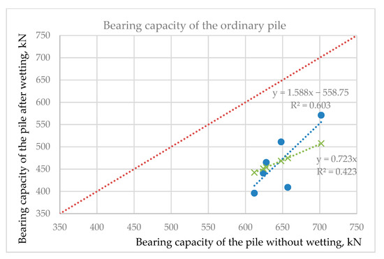
Figure 12.
Comparative diagram of the bearing capacity of ordinary piles with and without wetting.
From the obtained linear dependencies, linear correlation coefficients were determined, reflecting the degree of closeness of the relationship between two variables. In our case, the correlation coefficient is determined by the following formula:
The correlation coefficient values change in the range: . If the value of the coefficient satisfies the condition , then the relationship between the two variables is weak; if , the relationship is average; if , the relationship is close.
In the case of piles with a protective shell, the obtained correlation coefficient for a straight line not crossing the origin is equal to 0.039, which indicates a weak connection between the function and the variables. For a straight line passing through the origin, the correlation coefficient is 0.61, which indicates the average relationship of the function with the variables. In the case of the ordinary pile, a similar pattern appears. Therefore, to determine the average value of the decrease in the bearing capacity because of wetting the near-pile soils, in both cases, we used linear functions that do not intersect the origin. Thus, after wetting an ordinary pile, the bearing capacity on average decreased by (1–0.723) · 100 = 27.7% (19–38%, see Table 4), while a pile with a protective and load-bearing shell decreased by (1–0.911) · 100 = 8.9% (4–14%, see Table 3).
4. Numerical Modeling of a Bored Pile with a Protective Shell in the Plaxis 2D Discussion
The modeling of a bored pile with a protective shell was carried out in an axisymmetric formulation of the two-dimensional Coulomb–Mohr model. The dimensions of the geometric model were taken on the condition that the stress distribution would be negligible within a given zone.
Figure 13 shows a geometric model for the numerical modeling of a bored pile with a protective shell, including a geotechnical element of the site, a pile model with a shell, and a linearly distributed force for a static loading pile.
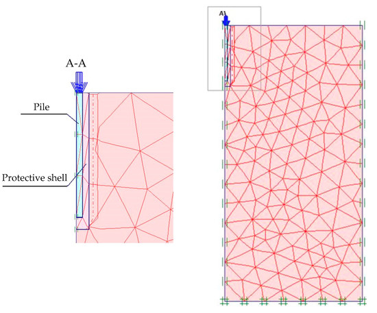
Figure 13.
Geometric model of numerical simulation of a bored pile with a protective shell.
A simulation was carried out for static tests of a 4 m pile with a protective shell. The pile and the shell represent a single conditional foundation, so there was no need to designate an interface between the pile and the shell; in other words, the possibility of the pile slipping through the protective shell was excluded. According to laboratory and field studies of the soil massif adjacent to the pile, at this construction site, the thickness of the protective shell when the sodium silicate is fed under a pressure of 5–6 atm, on average, is 0.95–1.15 d, where d is the pile diameter. In the numerical modeling, the average value of the containment thickness was taken to be 1.05 d = 0.42 m.
The boundary conditions of the model walls were set in the form of hinged-movable supports with free displacement along the y-axis and displacement along the x-axis = 0. The base of the model was set as a solid embedment, displacement along the x-axis = 0 and y-axis = 0. In the Plaxis software package, these types of boundary conditions were set automatically, as it is suitable for solving most geotechnical problems. The finite element mesh was generated automatically by the program and was a system of triangles. The construction method was based on the stable triangulation principle, which helped to find the optimal mesh sizes.
Before the start of the calculation, the initial conditions were determined, which included the initial geometric structure of groundwater and the initial state of effective stresses. The first computational stage included modeling of the natural stresses caused by gravitational forces; in the second stage—a uniformly distributed load, emitting a static load test loading, was applied to the pile model (Figure 13).
The main design parameters of geotechnical elements for the Coulomb–Mohr model were taken based on the geotechnical surveys described in Table 1. The parameters of the containment shell, presented in the form of soil hardened with sodium silicate, were taken based on numerous laboratory tests of hardened soil samples. The physical and mechanical values of the soil, shell, and pile accepted for modeling are presented in Table 5.
Table 5.
Accepted simulation parameters.
5. Discussion
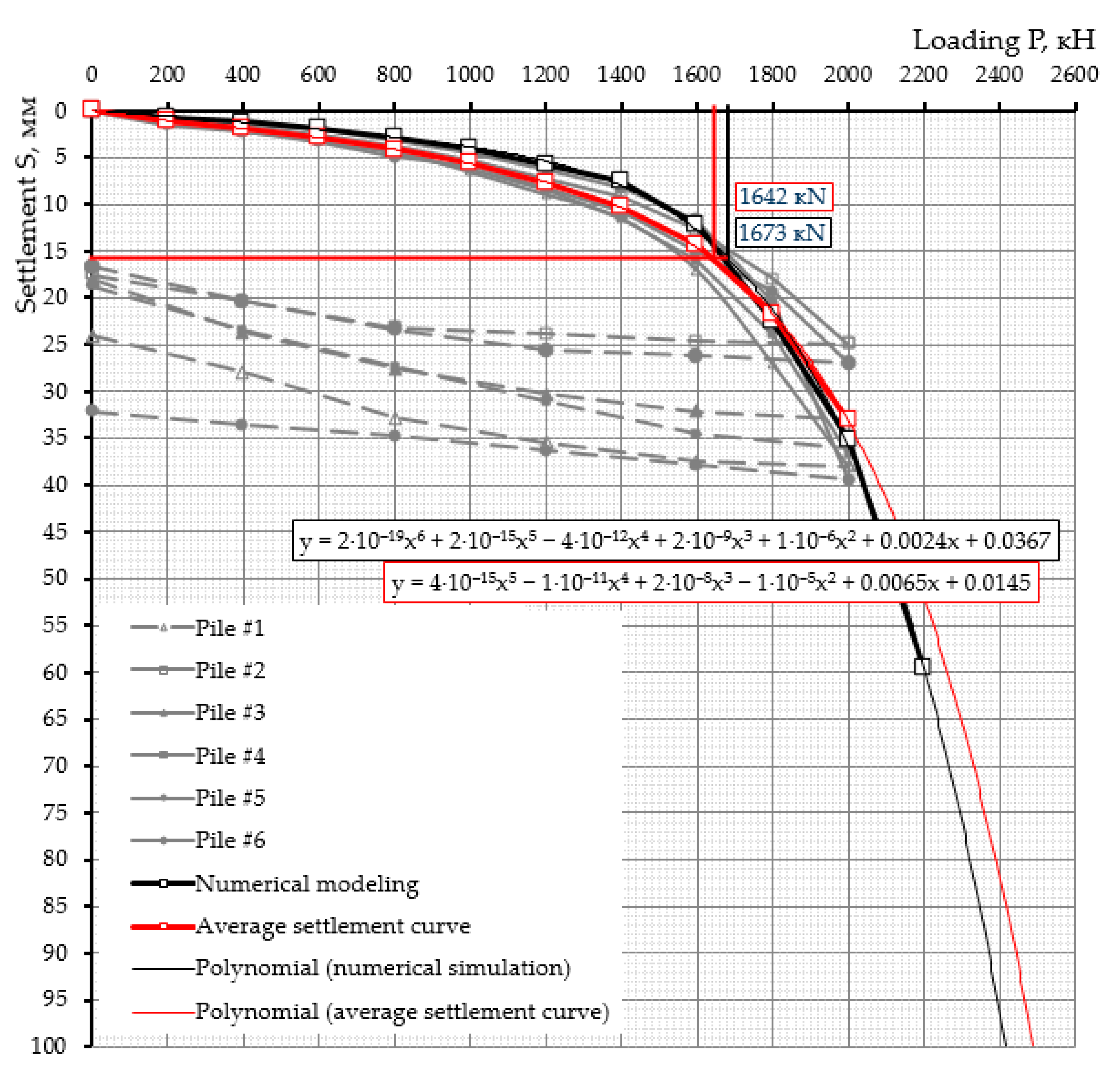
The protective silicate shell of the new design is technologically different from the previously known methods of ground improvement, but it was also more accurate from the distribution of sodium silicate solution around and beneath the pile, as well as posed better suffusion- and water-impermeable insolation. The results of in situ static loading tests showed that the bearing capacity of the piles casted in protective silicate shells was exceeded by 2.5 times compared to the bearing capacity of the ordinary bored piles without preliminary wetting of the soils and 3.2 times after prolonged soil wetting. Analyzing the loading–settlement curves from six experimental zones in Figure 14, we can conclude that the loading–settlement curve obtained by numerical modeling had a close relationship with the average experimental curve obtained when testing six SLT with the protective shell. The graph also showed the polynomial characteristics of the obtained curves, with correlation coefficients of 0.999 for both curves. The polynomial curve comprised possible transversely increasing and decreasing extreme pikes of the dependence. In this case, the least squares fit was performed using the following formula:
where b, c1…cn are polynomial function constants.
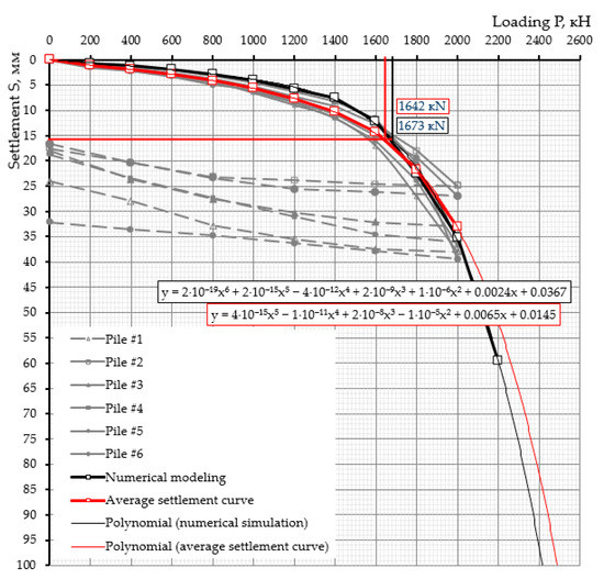
Figure 14.
Comparison of “load–settlement” curves obtained by field tests and numerical modeling.
Using polynomial equations, the settlement was predicted with a further loading pile, both for the experimental and calculated curves. The effectiveness of the proposed technology for the installation of bored piles in a protective and load-bearing shell was given in comparison with the construction technology of the ordinary pile.
As it was determined, the bearing capacity of piles with a protective and bearing shell exceeded the bearing capacity of the ordinary pile by 2.5 times on average. According to this ratio, the required number of ordinary piles and the substitutive amount of piles with a protective and load-bearing shell might be found. Thus, five ordinary piles would respond to the same bearing capacity as two piles with a protective shell. In our example, 645 · 5 = 3225 ≈ 1646 · 2 = 3292 kN. The total cost of the materials and labor costs for the construction of the piles is presented in Table 6, as well as the economic efficiency, based on modern prices for the installation of bored piles in Kazakhstan.
Table 6.
Calculation of economic efficiency of piles with protective shell.
The advantages of the construction of a bored pile with a protective shell, built by impregnating the near-pile soils with silicate solution, can be considered its environmental friendliness, irreversible corrosion resistance, water resistance, and optimal distribution of strength along the entire length of the shell and in the near-pile zone.
The calculation of economic efficiency of the piles with a protective and bearing shell in Table 6 confirmed the results obtained according to the functional relationship to and expressed by the kx coefficient. Thus, it was finally obtained that with prolonged wetting of a traditional pile, the bearing capacity decreased on average by 28% (19–38%), and in the case of a pile with a protective and bearing shell, the bearing capacity decreased by 8–9% (4–14%) after wetting.
6. Conclusions
Full-scale static load tests and numerical modeling of bored piles with and without a protective silicate shell of a new design in saline silty-clayey soils were performed in this study, based on which the following outcomes can be highlighted:
- A method for the construction of a bored pile with a protective shell cast from a silicate solution was developed. The copyright, novelty, and efficiency of the proposed technology were confirmed by a patent [34] and by the results of experimental approbation.
- The physicochemical processes of the formation of a protective shell around a bored pile was described in the process of the interaction of a silicate solution with salts present in saline soils, as a result of the crystallization of acidic silica gel films on soil particles and capillaries.
- According to the results of static pile load (SLT) tests of ordinary piles and piles with a protective and bearing shell of the new design, the bearing capacity of the casts exceeded the bearing capacity of ordinary piles, without soil wetting, by 2.5 times on average, and after soil wetting—by 3.2 times.
- According to the SLT results, soil wetting greatly affected the bearing capacity of ordinary piles, while piles with protective silicate shells were more stable due to the increased cross-section of the support area. It was determined that soil wetting decreased the bearing capacity of the ordinary pile by 27.7% on average, and by 8.9% in the case of a pile with protective and the load-bearing silicate shell.
- Numerical modeling of the piles with a protective shell showed a great convergence of the results of modeling and static pile load tests results. The polynomial functional dependence of the load–settlement was obtained, with which a prediction of the numerical and averaged experimental curve “load–settlement” was made with an accuracy of 99.9%.
- An economic comparison of the costs of the material and construction of ordinary piles and piles with a protective and load-bearing shell confirmed an extended economic effect of the developed technology of piling in a protective silicate shell with a significant reduction in the cost of piling, equal to 27.85%.
Author Contributions
Conceptualization, B.B.U.; methodology, B.B.U.; software, N.A.; validation, B.B.U. and N.A.; formal analysis, B.Z.U. and A.S.; investigation, B.B.U.; resources, B.B.U. and A.S.; data curation, B.B.U.; writing—original draft preparation, A.S.; writing—review and editing, A.S.; visualization, A.S.; supervision, B.Z.U.; project administration, N.A. and B.Z.U.; funding acquisition, B.Z.U. All authors have read and agreed to the published version of the manuscript.
Funding
This research was carried out in the frame of the Ph.D. research of B.B.U., funded by the first author and partly covered by the educational grant of the Ministry of Education and Science of the Republic of Kazakhstan.
Institutional Review Board Statement
Not applicable.
Informed Consent Statement
Not applicable.
Data Availability Statement
The data presented in this study are available on request from the corresponding author. The data are not publicly available, due to maintaining the secrecy of geographic coordinates of the construction objects.
Acknowledgments
The authors are grateful to the colleagues of the Geotechnical Institute and “Laboratory of concrete and reinforced concrete products and structures” at the test complex, “ENU-Lab” of the L.N. Gumilyov Eurasian National University, ʺKGS-Astana,” engineering laboratory “Integrated development of mineral resources” at the Karaganda State Technical University and test center “Karagandy Techno Service” for their support in conducting laboratory and field tests, engineering and geological surveys.
Conflicts of Interest
The authors declare no conflict of interest. The funders had no role in the design of the study; in the collection, analyses, or interpretation of data; in the writing of the manuscript, or in the decision to publish the results.
References
- Adikov, M.T.; Podkolzin, V.V. Experience in Studying the Building Properties of Saline Soils in South Kazakhstan; Express Information: Alma-Ata, Kazakhstan, 1976. (In Russian) [Google Scholar]
- Ministry of National Economy of the Republic of Kazakhstan. Design of Buildings on Salt Soils: Regulatory-Technical Guide; NTP RK 07-01.1-2011; Office of Technical Regulation and Rationing of the Construction Committee, Housing and Communal Services and Management Land Resources of the Ministry of National Economy of the Republic of Kazakhstan: Astana, Kazakhstan, 2011. Available online: https://online.zakon.kz/Document/?doc_id=34440425 (accessed on 21 July 2021). (In Russian)
- Ministry of National Economy of the Republic of Kazakhstan. Foundations of Buildings and Structures; SP RK 5.01-102-2013; Office of Technical Regulation and Rationing of the Construction Committee, Housing and Communal Services and Management Land Resources of the Ministry of National Economy of the Republic of Kazakhstan: Astana, Kazakhstan, 2013. Available online: https://online.zakon.kz/Document/?doc_id=39343712 (accessed on 21 July 2021). (In Russian)
- Pan, X.; Shi, Z.; Shi, C.; Ling, T.-C.; Li, N. A review on concrete surface treatment Part I: Types and mechanisms. Constr. Build. Mater. 2017, 132, 578–590. [Google Scholar] [CrossRef]
- De Brito, J.; Kurda, R. The past and future of sustainable concrete: A critical review and new strategies on cement-based materials. J. Clean. Prod. 2021, 281, 123558. [Google Scholar] [CrossRef]
- Zerda, A.S.; Lesser, A.J. Intercalated clay nanocomposites: Morphology, mechanics, and fracture behavior. J. Polym. Sci. B Polym. Phys. 2001, 39, 1137–1146. [Google Scholar] [CrossRef]
- Wang, W.; Lockwood, K.; Boyd, L.M.; Davidson, M.D.; Movafaghi, S.; Vahabi, H.; Khetani, S.R.; Kota, A.K. Super hydrophobic coatings with edible materials. ACS Appl. Mater. Interfaces 2016, 8, 18664–18668. [Google Scholar] [CrossRef]
- Kozak, A. Multi-criteria assessment of an acrylic coating exposed to natural and artificial weathering. Procedia Eng. 2015, 108, 664–672. [Google Scholar] [CrossRef] [Green Version]
- Elnaggar, E.M.; Elsokkary, T.M.; Shohide, M.A.; El-Sabbagh, B.A.; Abdel Gawwad, H.A. Surface protection of concrete by new protective coating. Constr. Build. Mater. 2019, 220, 245–252. [Google Scholar] [CrossRef]
- Scarfato, P.; Di Maio, L.; Fariello, M.L.; Russo, P.; Incarnato, L. Preparation and evaluation of polymer/clay nanocomposite surface treatments for concrete durability enhancement. Cem. Concr. Compos. 2012, 34, 297–305. [Google Scholar] [CrossRef]
- Carmona-Quiroga, P.M.; Martínez-Ramírez, S.; Sobrados, I.; Blanco-Varela, M.T. Interaction between two anti-graffiti treatments and cement mortar (paste). Cem. Concr. Res. 2010, 40, 723–730. [Google Scholar] [CrossRef]
- Peng, C.; Chen, Z.; Tiwari, M.K. All-organic superhydrophobic coatings with mechanochemical robustness and liquid impalement resistance. Nat. Mater. 2018, 17, 355–360. [Google Scholar] [CrossRef]
- Li, G.; Yue, J.; Guo, C.; Ji, Y. Influences of modified nanoparticles on hydro phobicity of concrete with organic film coating. Constr. Build. Mater. 2018, 169, 1–7. [Google Scholar] [CrossRef]
- Esposito Corcione, C.; Striani, R.; Capone, C.; Molfetta, M.; Vendetta, S.; Frigione, M. Preliminary study of the application of a novel hydrophobic photo polymerizable nano-structured coating on concrete substrates. Prog. Org. Coat. 2018, 121, 82–189. [Google Scholar] [CrossRef]
- Mora, E.; Gonzalez, G.; Romero, P.; Castellon, E. Control of water absorption in concrete materials by modification with hybrid hydrophobic silica particles. Constr. Build. Mater. 2019, 221, 210–218. [Google Scholar] [CrossRef]
- Feng, Z.; Wang, F.; Xie, T.; Ou, J.; Xue, M.; Li, W. Integral hydrophobic concrete without using silane. Constr. Build. Mater. 2019, 227, 116678. [Google Scholar] [CrossRef]
- Chen, S.; Li, X.; Li, Y.; Sun, J. Intumescent flame-retardant and self-healing superhydrophobic coatings on cotton fabric. ACS Nano 2015, 9, 4070–4076. [Google Scholar] [CrossRef] [PubMed]
- Chen, B.; Qiu, J.; Sakai, E.; Kanazawa, N.; Liang, R.; Feng, H. Robust and superhydrophobic surface modification by a “Paintþ Adhesive” method: Applications in self-cleaning after oil contamination and oilewater separation. ACS Appl. Mater. Interfaces 2016, 8, 17659–17667. [Google Scholar] [CrossRef]
- Iqbal, R.; Majhy, B.; Sen, A. Facile fabrication and characterization of a PDMS derived candle soot coated stable biocompatible superhydrophobic and superhemophobic surface. ACS Appl. Mater. Interfaces 2017, 9, 31170–31180. [Google Scholar] [CrossRef]
- Li, J.; Zhao, Z.; Li, D.; Tian, H.; Zha, F.; Feng, H.; Guo, L. Smart candle soot coated membranes for on-demand immiscible oil/water mixture and emulsion switchable separation. Nanoscale 2017, 9, 13610–13617. [Google Scholar] [CrossRef]
- Pan, S.; Guo, R.; Bjornmalm, M.; Richardson, J.J.; Li, L.; Peng, C.; Bertleff-Zieschang, N.; Xu, W.; Jiang, J.; Caruso, F. Coatings super-repellent to ultralow surface tension liquids. Nat. Mater. 2018, 17, 1040–1047. [Google Scholar] [CrossRef]
- Husni, H.; Nazari, M.R.; Yee, H.M.; Rohim, R.; Yusuff, A.; Mohd Ariff, M.A.; Ahmad, N.N.R.; Leo, C.P.; Junaidi, M.U.M. Superhydrophobic rice husk ash coating on concrete. Constr. Build. Mater. 2017, 144, 385–391. [Google Scholar] [CrossRef]
- Jia, L.; Shi, C.; Pan, X.; Zhang, J.; Wu, L. Effects of inorganic surface treatment on water permeability of cement-based materials. Cem. Concr. Compos. 2016, 67, 85–92. [Google Scholar] [CrossRef]
- Jiang, L.; Xue, X.; Zhang, W.; Yang, J.; Zhang, H.; Li, Y.; Zhang, R.; Zhang, Z.; Xu, L.; Qu, J.; et al. The investigation of factors affecting the water impermeability of inorganic sodium silicate-based concrete sealers. Constr. Build. Mater. 2015, 93, 729–736. [Google Scholar] [CrossRef]
- Moon, H.Y.; Shin, D.G.; Choi, D.S. Evaluation of the durability of mortar and concrete applied with inorganic coating material and surface treatment system. Constr. Build. Mater. 2007, 21, 362–369. [Google Scholar] [CrossRef]
- Xu, J.; Li, Y.; Wang, S.; Ren, J.; Ding, J.; Wang, Q.; Cheng, D.; Yu, F. Cement-Improved Wetting Resistance of Coarse Saline Soils in Northwest China. J. Test. Eval. 2021, 49, 229–254. [Google Scholar] [CrossRef]
- Yaghoubi, M.; Arulrajah, A.; Disfani, M.M.; Horpibulsuk, S.; Bo, M.W.; Darmawan, S. Effects of industrial by-product based geopolymers on the strength development of a soft soil. Soils Found. 2018, 58, 716–728. [Google Scholar] [CrossRef]
- Chen, Y.; Zhang, W.; Zhao, L.; Peng, Z. Field in-situ stabilization of bored pile mud: Engineering properties and application for pavement. Constr. Build. Mater. 2018, 165, 541–547. [Google Scholar] [CrossRef]
- Unaibayev, B.B.; Unaibayev, B.Z.; Andreyachshenko, V. Cast-in-situ piles encasements based on oil-bituminous rocks (kirs) in saline soils. Sci. Rev. Eng. Environ. Sci. 2021, 30, 51–61. [Google Scholar] [CrossRef]
- Ministry of National Economy of the Republic of Kazakhstan. Construction Structures Corrosion Protection; SP RK 2.01-101-2013; Office of Technical Regulation and Rationing of the Construction Committee, Housing and Communal Services and Management Land Resources of the Ministry of National Economy of the Republic of Kazakhstan: Astana, Kazakhstan, 2013. Available online: https://online.zakon.kz/Document/?doc_id=33796763 (accessed on 21 July 2021). (In Russian)
- Karimov, Y.L.; Latipov, Z.Y.; Kayumov, O.A.; Boimurodov, N.A. Development of the technology for fixing salt waste from the mine of the Tyubegatan mining complex. Univers. Tech. Sci. Electron. Sci. J. 2020, 12, 81. Available online: https://7universum.com/ru/tech/archive/item/11071 (accessed on 23 March 2021).
- Ministry of National Economy of the Republic of Kazakhstan. Pile Foundations; SP RK 5.01-103-2013; Office of Technical Regulation and Rationing of the Construction Committee, Housing and Communal Services and Management Land Resources of the Ministry of National Economy of the Republic of Kazakhstan: Astana, Kazakhstan, 2013. Available online: https://online.zakon.kz/Document/?doc_id=38144008 (accessed on 21 July 2021). (In Russian)
- State Standard GOST 5686-2012; Soils Field Test: Methods for Piles; Standartinform: Moscow, Russian, 2012. (In Russian)
- A Method of Erecting a Bored Pile in Saline Loess Subsidence Soils. Innovative Patent for Invention No. 22796, Bulletin No. 8. 16 August 2010. (In Russian).

Publisher’s Note: MDPI stays neutral with regard to jurisdictional claims in published maps and institutional affiliations. |
© 2021 by the authors. Licensee MDPI, Basel, Switzerland. This article is an open access article distributed under the terms and conditions of the Creative Commons Attribution (CC BY) license (https://creativecommons.org/licenses/by/4.0/).