
Design of an Integrated Heat Dissipation Mechanism for a Quad Transmit Receive Module of Array Radar


Abstract
:1. Introduction
2. System Architecture and Problem Description
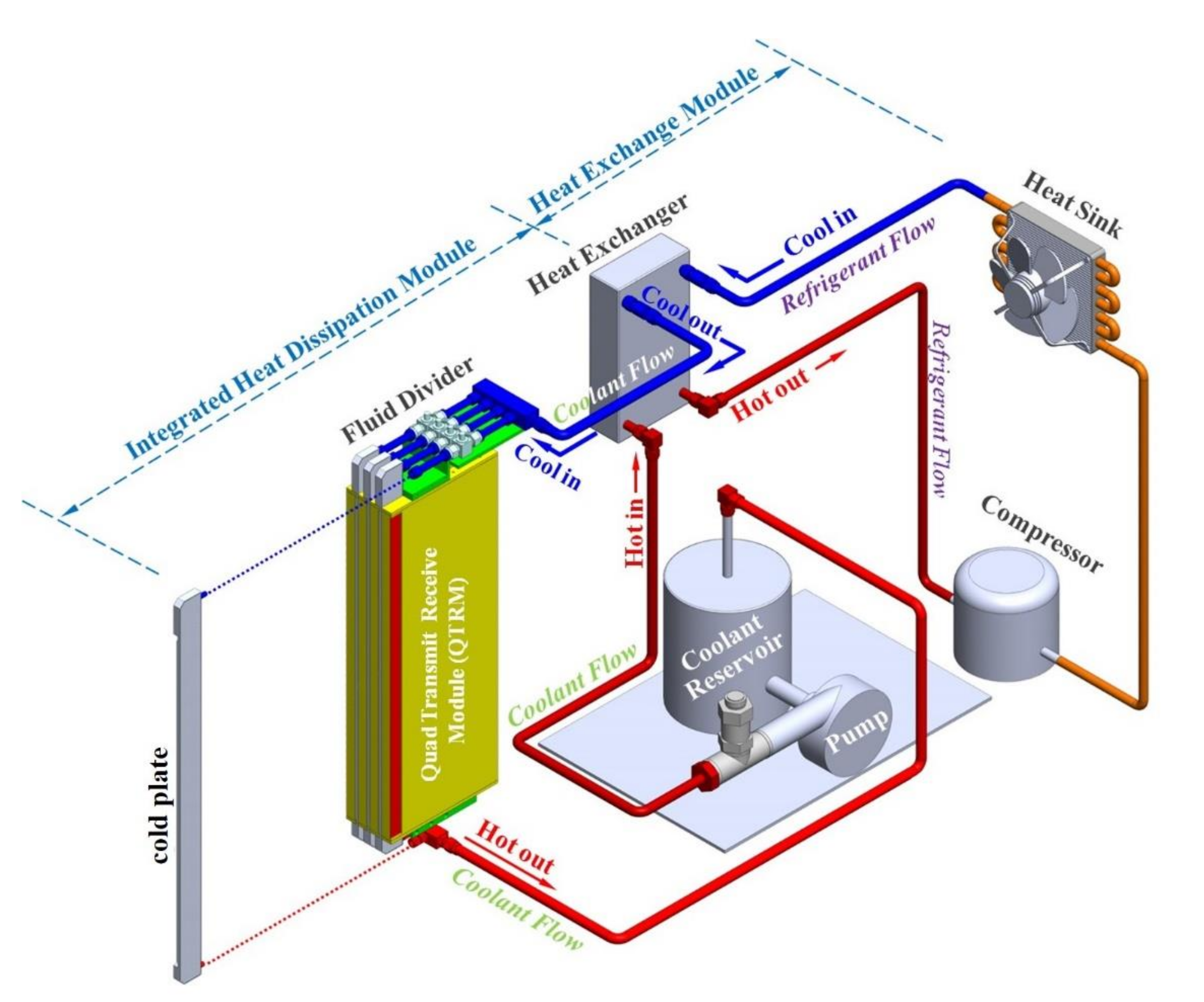
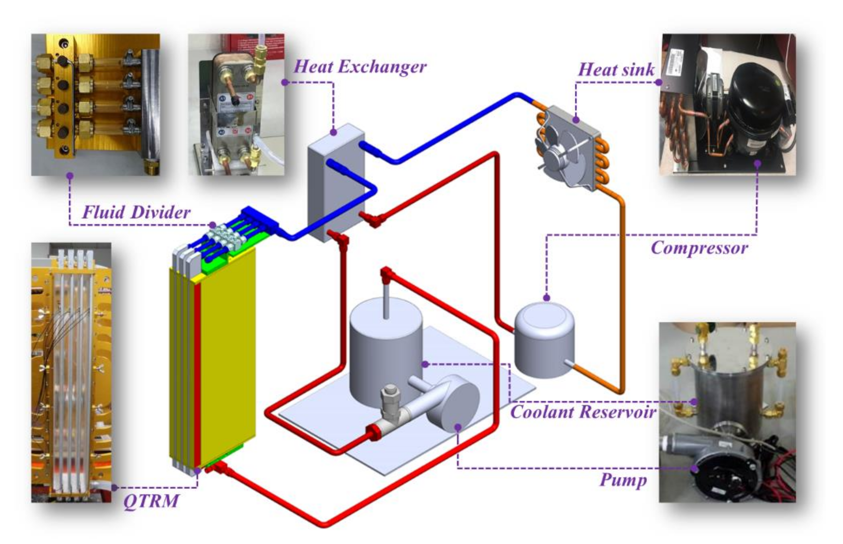
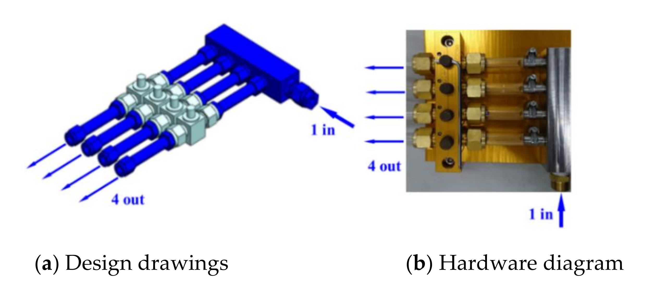
2.1. Architecture of the Integrated Heat Dissipation Module
2.2. Optimal Design of the Fluid Circulation-Type Cold Plate
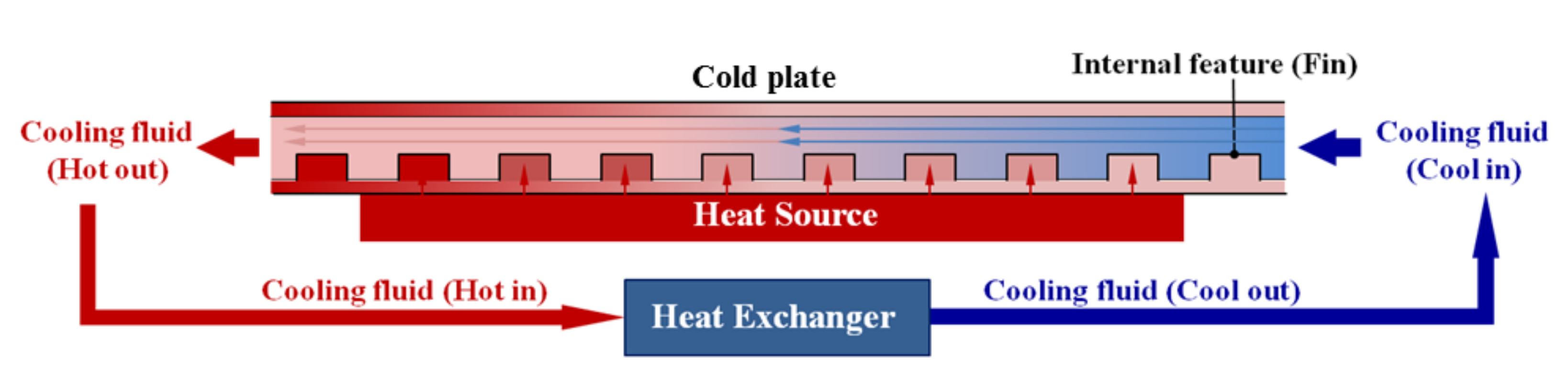
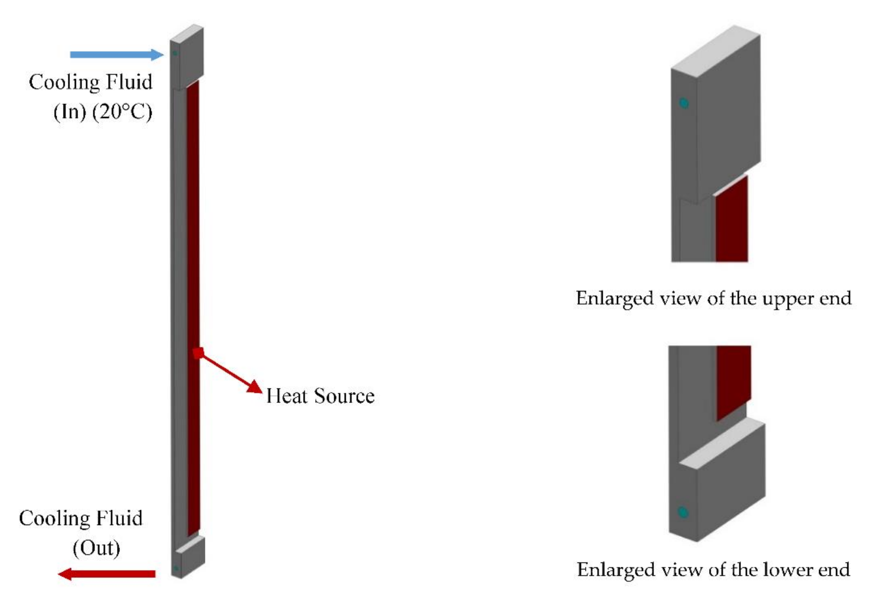
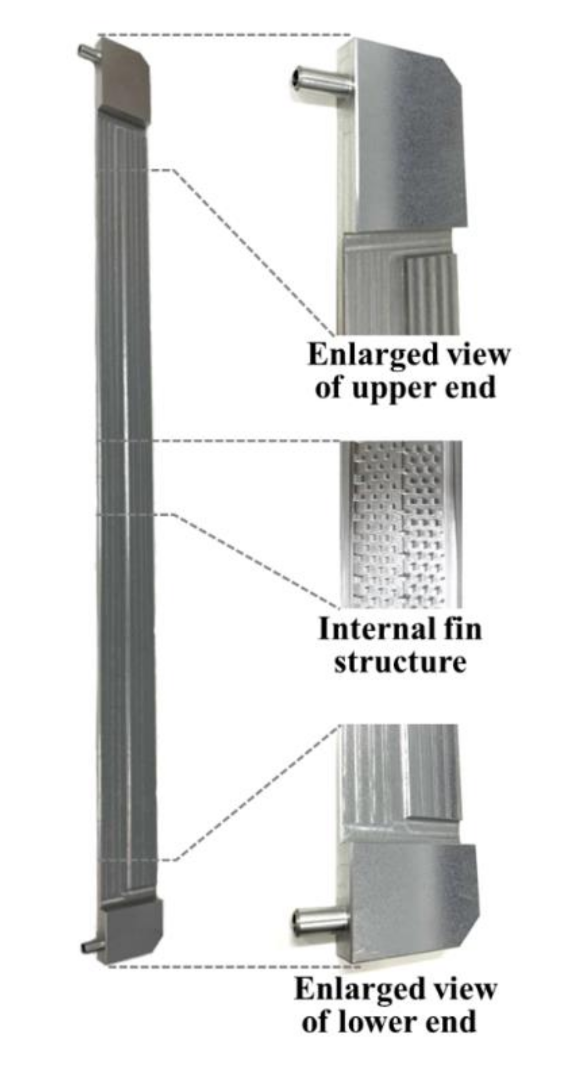
3. Design and System Description of the Cold Plate
4. Optimal Design of the Heat Dissipation Performance of the Fluid Cold Plate
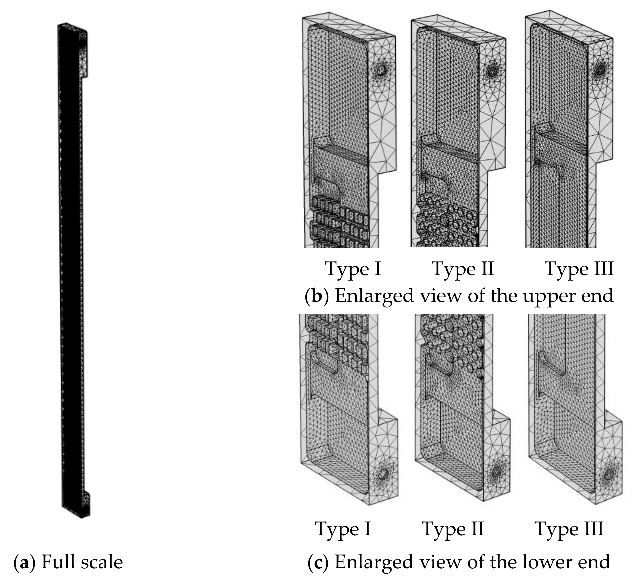
4.1. Mesh System Design
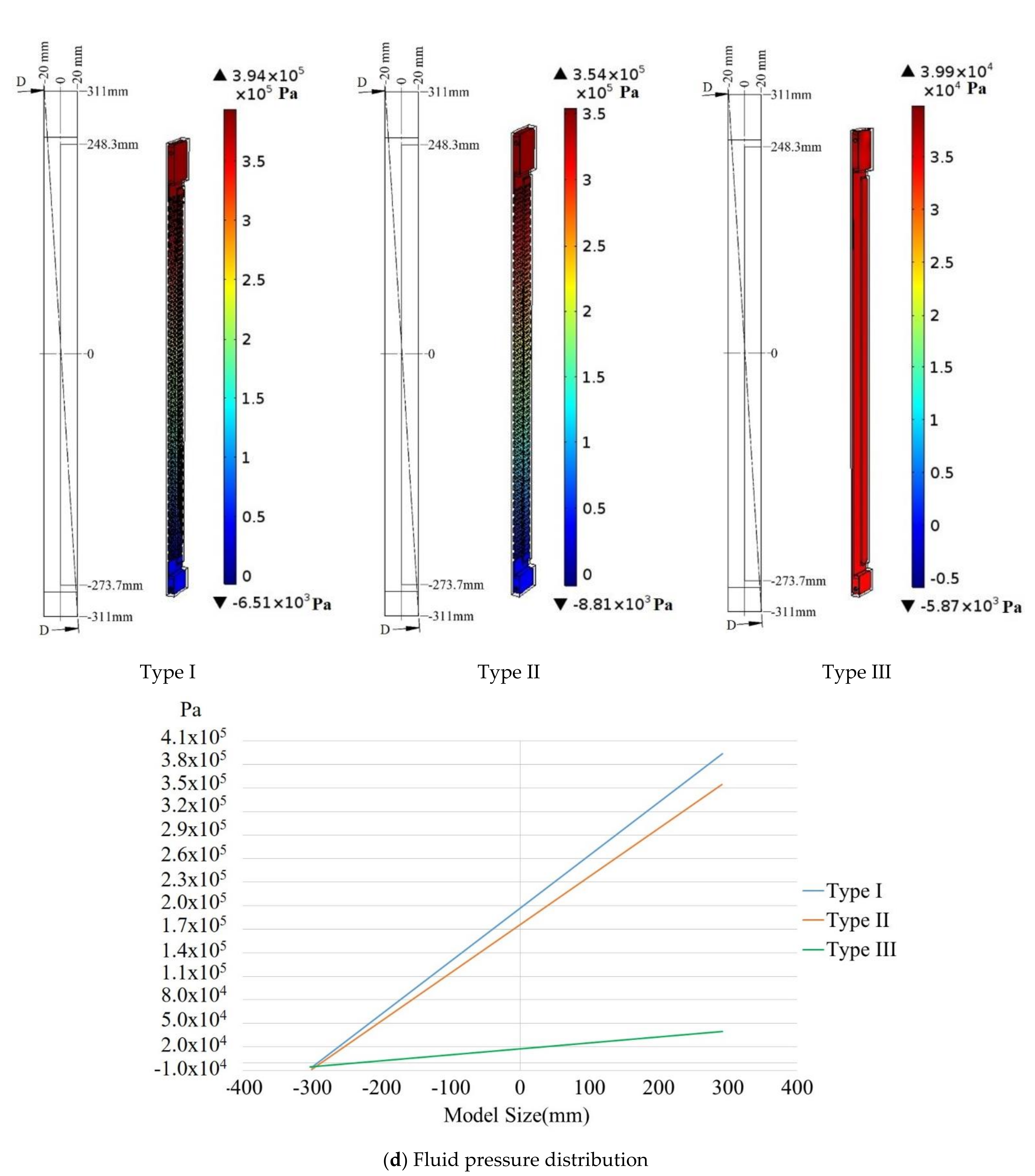
4.2. Simulation Results and Analysis
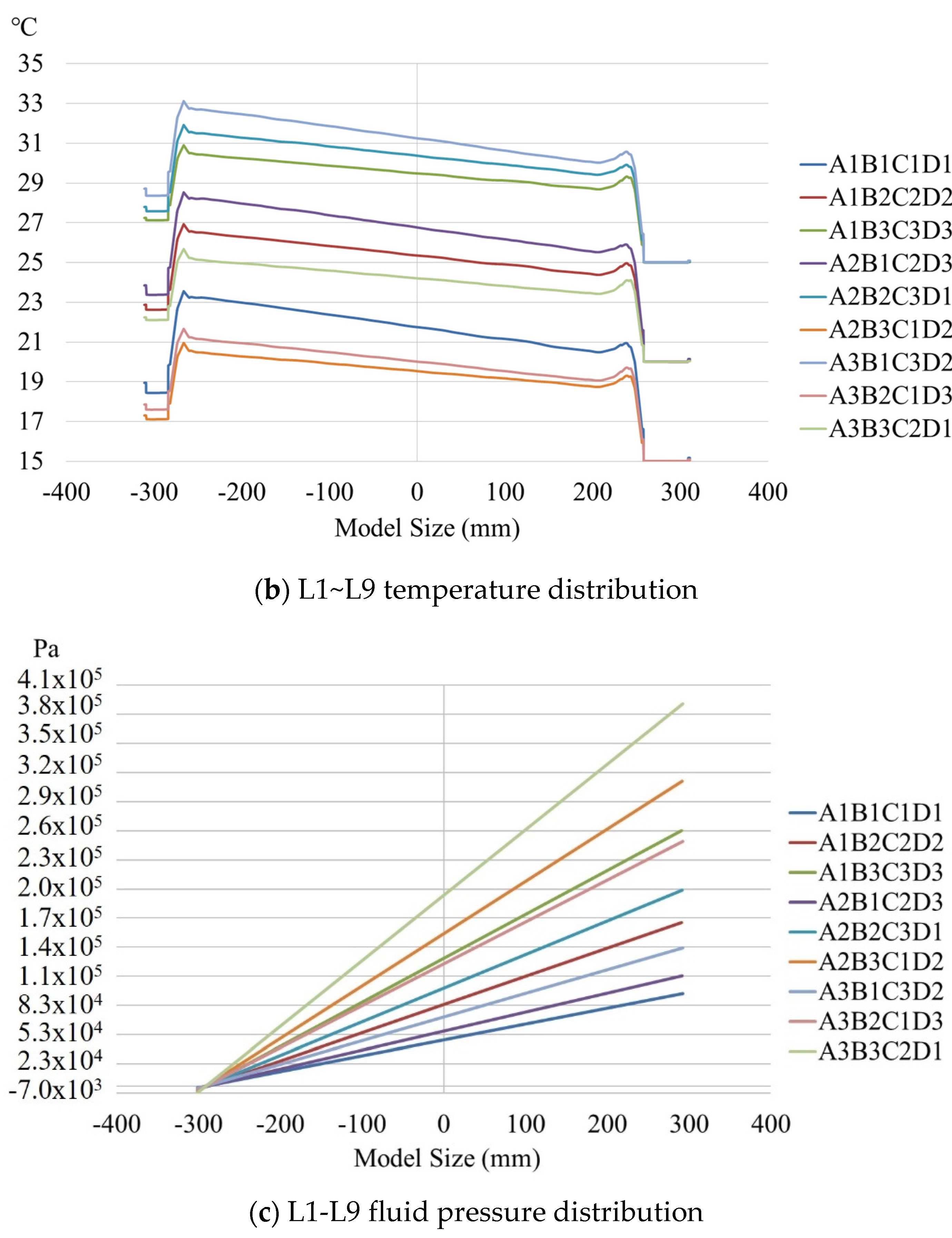
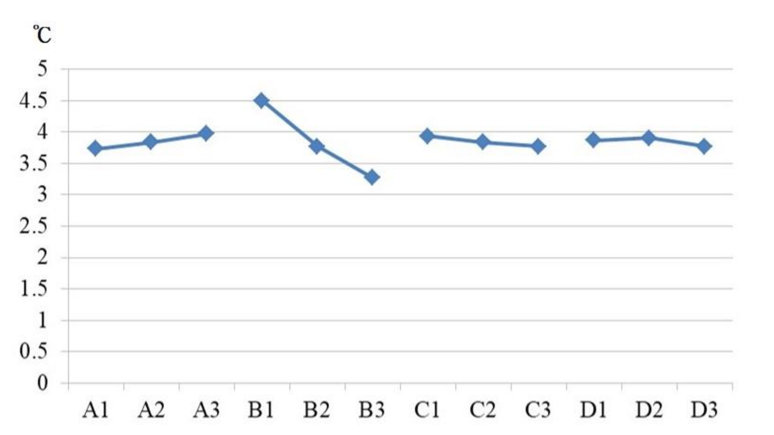
4.3. Optimizing the System Performance of the Parameter Design
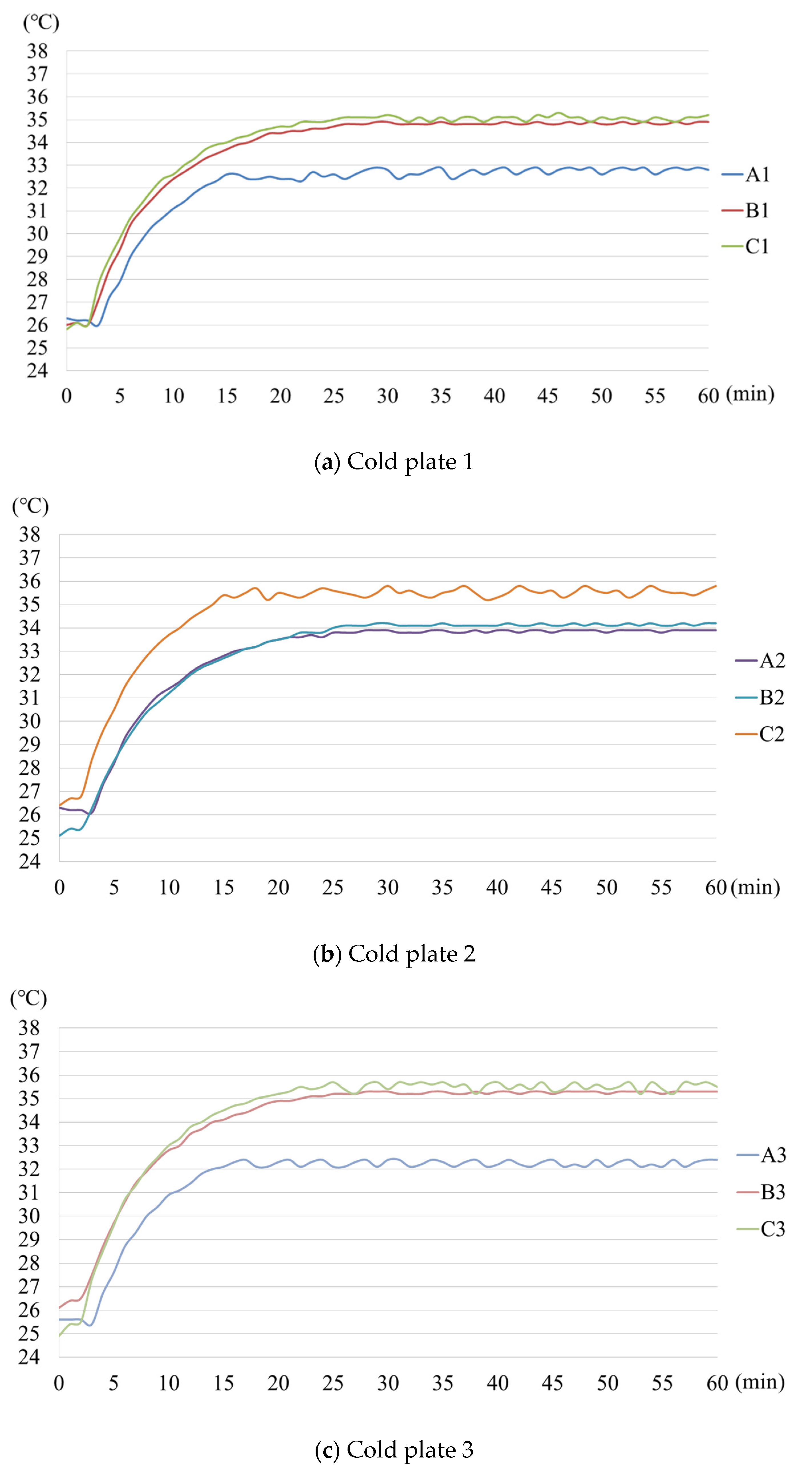
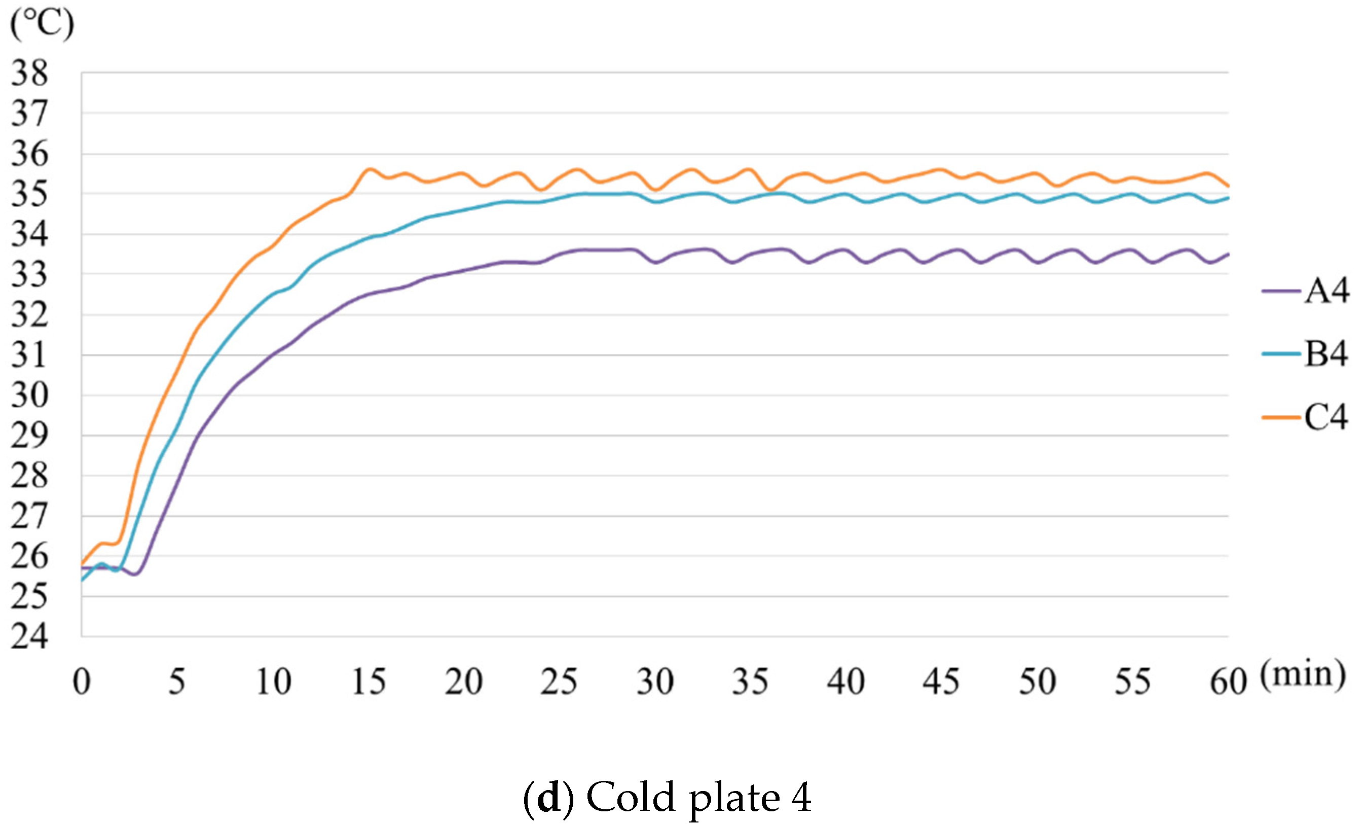
5. Experimental Verification
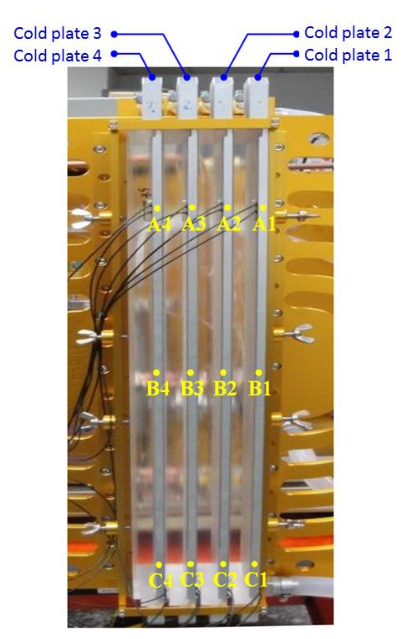
5.1. System Hardware Architecture
5.2. Heat Dissipation System Experiment
6. Conclusions
Author Contributions
Funding
Institutional Review Board Statement
Informed Consent Statement
Data Availability Statement
Acknowledgments
Conflicts of Interest
References
- Wiriyasart, S.; Naphon, P. Liquid impingement cooling of cold plate heat sink with different fin configurations: High heat flux applications. Int. J. Heat Mass Transfer. 2019, 140, 281–292. [Google Scholar] [CrossRef]
- Wiriyasart, S.; Naphon, P. Heat spreading of liquid jet impingement cooling of cold plate heat sink with different fin shapes. Case Stud. Therm. Eng. 2020, 20, 100638. [Google Scholar] [CrossRef]
- Zhang, H.; Li, C.; Zhang, R.; Lin, Y.; Fang, H. Thermal analysis of a 6s4p Lithium-ion battery pack cooled by cold plates based on a multi-domain modeling framework. Appl. Therm. Eng. 2020, 173, 115216. [Google Scholar] [CrossRef]
- Ho, J.Y.; Leong, K.C. Cylindrical porous inserts for enhancing the thermal and hydraulic performance of water-cooled cold plates. Appl. Therm. Eng. 2017, 121, 863–878. [Google Scholar] [CrossRef]
- Xu, X.; Tong, G.; Li, R. Numerical study and optimizing on cold plate splitter for lithium battery thermal management system. Appl.Therm. Eng. 2020, 167, 114787. [Google Scholar] [CrossRef]
- Deng, T.; Zhang, G.; Ran, Y. Study on thermal management of rectangular Li-ion battery with serpentine-channel cold plate. Int. J. Heat Mass Transfer. 2018, 125, 143–152. [Google Scholar] [CrossRef]
- Deng, T.; Zhang, G.; Ran, Y.; Liu, P. Thermal performance of lithium ion battery pack by using cold plate. Appl. Therm. Eng. 2019, 160, 114088. [Google Scholar] [CrossRef]
- Jarrett, A.; Kim, Y. Design optimization of electric vehicle battery cooling plates for thermal performance. J. Power Sources 2011, 196, 10359–10368. [Google Scholar] [CrossRef]
- Jarrett, A.; Kim, I.Y. Influence of operating conditions on the optimum design of electric vehicle battery cooling plates. J. Power Sources 2014, 245, 644–655. [Google Scholar] [CrossRef]
- Huo, Y.; Rao, Z.; Liu, X.; Zhao, J. Investigation of power battery thermal management by using mini-channel cold plate. Energy Convers. Manag. 2015, 89, 387–395. [Google Scholar] [CrossRef]
- Cova, P.; Delmonte, N.; Giuliani, F.; Citterio, M.; Latorre, S.; Lazzaroni, M.; Lanza, A. Thermal optimization of water heat sink for power converters with tight thermal constraints. Microelectron. Reliab. 2013, 53, 1760–1765. [Google Scholar] [CrossRef]
- Cova, P.; Delmonte, N.; Chiozzi, D.; Portesine, M.; Vaccaro, F.; Mantegazza, E. Water cold plates for high power converters: A software tool for easy optimized design. Microelectron. Reliab. 2018, 88–90, 801–805. [Google Scholar] [CrossRef]
- Cova, P.; Santoro, D.; Spaggiari, D.; Portesine, F.; Vaccaro, F.; Delmonte, N. CFD modeling of additive manufacturing liquid cold plates for more reliable power press-pack assemblie. Microelectron. Reliab. 2020, 114, 113734. [Google Scholar] [CrossRef]
- Cao, J.; He, Y.; Feng, J.; Lin, S.; Ling, Z.; Zhang, Z.; Fang, X. Mini-channel cold plate with nano phase change material emulsion for Li-ion battery under high-rate discharge. Appl. Energy 2020, 279, 115808. [Google Scholar] [CrossRef]
- Li, X.; Zhou, D.; Zhang, G.; Wang, C.; Lin, R.; Zhong, Z. Experimental investigation of the thermal performance of silicon cold plate for battery thermal management system. Appl. Therm. Eng. 2019, 155, 331–340. [Google Scholar] [CrossRef]
- Zhang, Q.; Ye, H.; Wang, Z.J. A comparative study of launch canister thermal control systems using a liquid or gas working medium. Appl. Therm. Eng. 2018, 131, 125–131. [Google Scholar] [CrossRef]
- Frazier, W.E. Metal additive manufacturing: A review. J. Mater. Eng. Perform. 2014, 23, 1917–1928. [Google Scholar] [CrossRef]
- Fletcher, K.K.; Sparks, T.E.; Flood, A.; Liou, F. A SOA approach to improve performance of metal additive manufacturing simulation. In Proceedings of the 2017 IEEE International Conference on Cognitive Computing (ICCC), Honolulu, HI, USA, 25–30 June 2017; pp. 140–143. [Google Scholar]
- Lin, S.L.; Lin, C.C.; Lin, D.Y.; Chuang, C.S. Laser additive manufacturing technology in titanium 64 implant of microstructure fabrication and analysis. In Proceedings of the 8th Annual IEEE International Conference on Nano/Micro Engineered and Molecular Systems, Suzhou, China, 7–10 April 2013; pp. 594–597. [Google Scholar]
- Yan, Y.; Ding, C.; Ngo, K.D.T.; Mei, Y.; Lu, G. Additive manufacturing of planar inductor for power electronics applications. In Proceedings of the International Symposium on 3D Power Electronics Integration and Manufacturing (3D-PEIM), Raleigh, NC, USA, 13–15 June 2016; pp. 1–16. [Google Scholar]
- Yuan, L. Solidification defects in additive manufactured materials. JOM 2019, 71, 3221–3222. [Google Scholar] [CrossRef] [Green Version]
- Wang, D.; Wang, Z.; Li, K.; Ma, J.; Liu, W.; Shen, Z. Cracking in laser additively manufactured W: Initiation mechanism and a suppression approach by alloying. Mater. Des. 2019, 162, 384–393. [Google Scholar] [CrossRef]
- Kim, F.H.; Moylan, S.P. Literature review of metal additive manufacturing defects. NIST Adv. Manuf. Ser. 2018, 100–116. [Google Scholar] [CrossRef]
- Riemer, A.; Richard, H.A. Crack propagation in additive manufactured materials and structures. Procedia Struct. Integr. 2016, 2, 1229–1236. [Google Scholar] [CrossRef] [Green Version]
- Kandilikar, S.G.; Hayner, C.N. Liquid cooled cold plates for industrial high-power electronic devices—Thermal design and manufacturing considerations. Heat Transfer. Eng. 2009, 30, 918–930. [Google Scholar] [CrossRef]
- Kosar, A.; Peles, Y. Thermal-hydraulic performance of MEMS-based pin fin heat sink. J. Heat Transf. 2006, 128, 121–131. [Google Scholar] [CrossRef]
- Manglik, R.M.; Bergles, A.E. Heat transfer and pressure drop correlations for twisted-tape inserts in isothermal tubes: Part I—Laminar Flows. J. Heat Transf. 1993, 115, 881–889. [Google Scholar] [CrossRef]
- Vanapalli, S.; ter Brake, H.J.M.; Jansen, H.V.; Burger, J.F.; Holland, H.J.; Veenstra, T.T.; Elwenspoek, M.C. Pressure drop of laminar gas flows in a microchannel containing various pillar matrices. J. Micromech. Microeng. 2007, 17, 1381–1386. [Google Scholar] [CrossRef]
- Lee, Y.J.; Lee, P.S.; Chou, S.K. Enhanced thermal transport in microchannel using oblique fins. J. Heat Transf. 2012, 134, 101901-1–101901-10. [Google Scholar] [CrossRef]
- Boomsma, K.; Poulikakos, D.; Zwick, F. Metal foams as compact high performance heat exchangers. Mech. Mater. 2003, 35, 1161–1176. [Google Scholar] [CrossRef]
- Wirtz, R.A.; Xu, J.; Park, J.W.; Ruch, D. Thermal/fluid characteristics of 3-D woven mesh structures as heat exchanger surfaces. IEEE Trans. Comp. Packag. Technol. 2003, 26, 40–47. [Google Scholar] [CrossRef]
- Boomsma, K.; Poulikakos, D. On the effective thermal conductivity of a threedimensionally structured fluid-saturated metal foam. Int. J. Heat Mass Transf. 2000, 44, 827–836. [Google Scholar] [CrossRef]
- Dai, Z.; Nawaz, K.; Park, Y.G.; Bock, J.; Jacobi, A.M. Correcting and extending the Boomsma-Poulikakos effective thermal conductivity model for three-dimensional, fluid saturated metal foams. Int. Commun. Heat Mass Transf. 2010, 37, 575–580. [Google Scholar] [CrossRef]
- Yang, H.; Zhao, M.; Gu, Z.L.; Jin, L.W.; Chai, J.C. A further discussion on the effective thermal conductivity of metal foam: An improved model. Int. J. Heat Mass Transf. 2015, 86, 207–211. [Google Scholar] [CrossRef]
- Wong, M.; Owen, I.; Sutcliffe, C.J.; Puri, A. Convective heat transfer and pressure losses across novel heat sinks fabricated by selective laser melting. Int. J. Heat Mass Transf. 2009, 52, 281–288. [Google Scholar] [CrossRef]
- Ho, J.Y.; Wong, K.K.; Leong, K.C. Saturated pool boiling of FC-72 from enhanced surfaces produced by selective laser melting. Int. J. Heat Mass Transf. 2016, 99, 107–121. [Google Scholar] [CrossRef]
- Yu, G.; Xiong, L.; Du, C.; Chen, H. Simplified model and performance analysis for top insulated metal ceiling radiant cooling panels with serpentine tube arrangement. Case Stud. Therm. Eng. 2018, 11, 35–42. [Google Scholar] [CrossRef]
- Wang, Z.; Ye, H. Parametric analysis of the thermal shielding performance of a cold plate with a serpentine flow design. In ASTFE Digital Library; Begel House Inc.: Fort Lauderdale, FL, USA, 2018. [Google Scholar]
- Yang, F.; Lin, Y.; Wei, X.; Ye, H. Infrared suppression of a power-generation cabin with a cold plate system. Appl. Therm. Eng. 2019, 158, 113820. [Google Scholar] [CrossRef]


| Fluid Condition | Heat Transfer Condition | ||||
|---|---|---|---|---|---|
| No. | Item | Parameter/Condition | No. | Item | Parameter/Condition |
| 1 | Fluid pattern | Turbulent flow | 1 | Material | Aluminum alloy |
| 2 | Fluid material | Fluorinated liquid | 2 | Thermal conductivity | 155 W/mK |
| 3 | Inlet flow velocity | 5 m/s | 3 | Heat source | 210 W |
| 4 | Fluid inlet temperature | 20 °C | 4 | Boundary condition | Natural convection |
| 5 | Ambient temperature | 25 °C | 5 | Ambient temperature | 25 °C |
| 6 | Outlet Pressure | 0 Pa | |||
| Fluid Temperature Difference (°C) | Temperature Difference of Cold Plate (°C) | Heat Source Surface Temperature Difference (°C) | Fluid Velocity Difference (m/s) | Pressure Difference (kgf/cm2) | |
|---|---|---|---|---|---|
| Type I | 3.8 | 5.7 | 3.4 | 6.221 | 4.079 |
| Type II | 4.2 | 6.2 | 3.7 | 6.174 | 3.705 |
| Type III | 18.1 | 35.4 | 30.4 | 6.140 | 0.467 |
| Level | 1 | 2 | 3 | 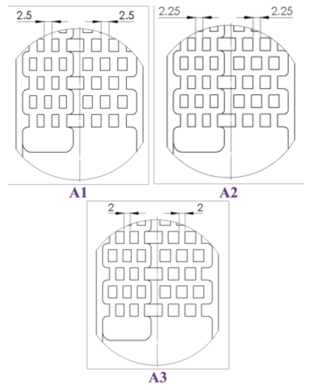 | |
| Factor | |||||
| A | Flow volume (mm3) | 62,470.72 | 60,958.72 | 59,446.72 | |
| B | Flow velocity (m/s) | 3 | 4 | 5 | |
| C | Initial coolant temperature (°C) | 15 | 20 | 25 | |
| D | Inlet diameter (mm) | 4 | 4 | 4 |
| Exp. | A | B | C | D | Heat Source Surface Temperature (°C) | Heat Source Surface Temperature Equalization (°C) |
|---|---|---|---|---|---|---|
| 1 | 1 | 1 | 1 | 1 | 19.1–23.6 | 4.5 |
| 2 | 1 | 2 | 2 | 2 | 23.2–26.9 | 3.7 |
| 3 | 1 | 3 | 3 | 3 | 27.7–30.7 | 3.0 |
| 4 | 2 | 1 | 2 | 3 | 24.1–28.5 | 4.4 |
| 5 | 2 | 2 | 3 | 1 | 28.2–31.9 | 3.7 |
| 6 | 2 | 3 | 1 | 2 | 17.6–21 | 3.4 |
| 7 | 3 | 1 | 3 | 2 | 28.5–33.1 | 4.6 |
| 8 | 3 | 2 | 1 | 3 | 17.8–21.7 | 3.9 |
| 9 | 3 | 3 | 2 | 1 | 22.3–25.7 | 3.4 |
| Quality Analysis | A | B | C | D |
|---|---|---|---|---|
| Level 1 | 3.73 | 4.50 | 3.93 | 3.87 |
| Level 2 | 3.83 | 3.77 | 3.83 | 3.90 |
| Level 3 | 3.97 | 3.27 | 3.77 | 3.77 |
| S/n | Product Name | Functions | Equipment Specifications |
|---|---|---|---|
| 1 | Quad transmit receive module of array radar | Heat source | 210 W (single) × 4- in = 840 W |
| 2 | Fluid cold plate | Fast heat conduction | Length: 622 mm × width: 40 mm × thickness: 12 mm |
| 3 | Shunt | Regulate flow rate (1 in and 4 out) | Self-made (the outer diameter of the water inlet is 1/2”) |
| 4 | Digital tachometer | Monitor/transmit traffic | GFM-FS-20 |
| 5 | Coolant reservoir | Storage/recovery of liquid | 2500 mL |
| 6 | Heat exchanger | Coolant cooling | Hard-welded K025 (Brazed Plate Heat Exchanger) |
| 7 | Radiator | Cooling | Embraco UFI12HBX-SD |
| 8 | Compressor | Provide refrigeration cycle power | Embraco FFI 12HBX, DC variable frequency compressor 1/3 hp |
| 9 | PUMP | Provide fluid circulation power | EWP 8041 |
| 10 | Temperature sensor (12EA) | Monitor the temperature of each point of the cold plate | K_Type temperature range 0 °C~1370 °C (±0.7 °C) |
Publisher’s Note: MDPI stays neutral with regard to jurisdictional claims in published maps and institutional affiliations. |
© 2021 by the authors. Licensee MDPI, Basel, Switzerland. This article is an open access article distributed under the terms and conditions of the Creative Commons Attribution (CC BY) license (https://creativecommons.org/licenses/by/4.0/).
Share and Cite
Liang, J.-Y.; Lee, Y.-L.; Mao, S.-W.; Tsai, M.-D. Design of an Integrated Heat Dissipation Mechanism for a Quad Transmit Receive Module of Array Radar. Appl. Sci. 2021, 11, 7054. https://doi.org/10.3390/app11157054
Liang J-Y, Lee Y-L, Mao S-W, Tsai M-D. Design of an Integrated Heat Dissipation Mechanism for a Quad Transmit Receive Module of Array Radar. Applied Sciences. 2021; 11(15):7054. https://doi.org/10.3390/app11157054
Chicago/Turabian StyleLiang, Jian-Yi, Yung-Lung Lee, Shih-Wei Mao, and Ming-Da Tsai. 2021. "Design of an Integrated Heat Dissipation Mechanism for a Quad Transmit Receive Module of Array Radar" Applied Sciences 11, no. 15: 7054. https://doi.org/10.3390/app11157054
APA StyleLiang, J.-Y., Lee, Y.-L., Mao, S.-W., & Tsai, M.-D. (2021). Design of an Integrated Heat Dissipation Mechanism for a Quad Transmit Receive Module of Array Radar. Applied Sciences, 11(15), 7054. https://doi.org/10.3390/app11157054