Abstract
The relevance of this research lies in the need to develop scientifically based methods for calculating and designing a transmission shaft with a hardened coating of increased strength and service life of a core drilling pump drive that can allow for a redistributing of resistance forces along the contact surfaces of the gear. This relevance is confirmed by the need to improve domestic methods for designing drive shafts of increased reliability which can ensure the development of frozen soils during deposits exploration. The purpose of the research is to increase the energy efficiency and service life of the high-loaded drive gear teeth of core drilling pump transmission shafts by justifying the critical loads and stresses in hardened gear coatings acting under intense wear of the contact surface with a broken contact symmetry. The criteria for the effective wear area with an uneven contact cross-section at the maximum bending moments of the transmission shaft of the drilling pump were justified and presented in the work. Additionally, the process of interaction of the transmission shaft gear teeth with the eccentric shaft gear at uneven axial torques was investigated. The effective power (Ng) of the gearing of the drive transmission shaft gear and the eccentric shaft gear, which characterizes the energy consumption of the drill bit depth stroke, was justified. This work also proposes a method of substantiating the technological and power parameters of the transmission shaft by using Legendre polynomials. A nomographic chart was developed for the determination of the dependence of the contact stress base cycles on the change in the load distribution factor and the contact spot deviation factor from the design axis λ.
1. Introduction
In modern mining and exploration drilling units, one of the most important installation units (and the main energy consumer) is the mud pumping unit (MPU).
The energy intensity of the drilling process significantly depends on the efficient operation of the transmission (drive) shaft of the pump, which is accompanied by large dynamic loads [1,2,3]. The range of changes in the pump cyclic load directly depends on the operating modes of the drill (start up - braking), the sum of the moments of forces that occur during different periods of drilling, and the deviation angle of the cutter at its entry. The energy efficiency of the pump operation largely depends on the dynamic, power, and energy characteristics of the transmission shaft, the kinematics of the gear and the design features of the drive.
Its technical condition and maximum permissible life indicators ensure the performance of technological operations that determine the efficiency and energy intensity of the well drilling process [3,4].
Studying the design and technological features of the pumping and the drilling unit, it was found that there are frequent failures along with its high margin of safety that can be associated with a sharp decrease in the supply pressure, Ps, and, as a result, in productivity. In some fields, intensive wear (i→max) of the cylinder-piston and plunger parts of the pump occurs during long-term core drilling at a milling cutter entry angle of up to 45°. This process can be explained by a sharp increase in the moments of resistance forces (Ff, …) with an increase in the supply volume of a special clay-containing solution to the casing head when the milling cutter slows down the speed.
Since the main criterion for the performance of shafts and gears is their fatigue strength (endurance), for the manufacture of most shafts thermally improved medium-carbon steels 40, 45, and 50 are used. They are used for the manufacture of shafts of stationary machines and mechanisms. The billet made of such steels is subjected to an improving heat treatment (HRC ≤ 36) before machining. The shafts are turned on a lathe, followed by grinding of the seats and trunnions on a grinding machine.
If the endurance of the thermally improved shafts is unsatisfactory or if they have wear sections, the shafts made of these steels are subjected to surface quenching with high-frequency currents heating and low tempering in these places.
Thus, there is a need to form and systematize the technical and operational indicators of the drilling rig and establish the dependence of changes in the quality criteria of a hardened coating that characterize the efficiency and service life of its operation.
2. Technological Methods for Increasing Service Life of Drilling Pumps
Analytical studies of the achievements of domestic and foreign scientists Zi-Ming, et.al. [4]. Sagar in the field of service life of drilling rigs (DR) show that the factors are insufficiently substantiated and a causal relationship has not been fully established between the failure of the main pump assemblies of drilling rigs with dynamic processes occurring in the structural elements of the gearing of the transmission shaft gear [4,5]. The importance of the task of studying the service life of pumps lies not only in the justification of the unit performance criteria but also in understanding the physical phenomena of cause and effect relationships of fatigue processes with technological and operational factors (Table 1) [6,7].

Table 1.
Factors influencing the determination of cause and effect relationships when justifying performance criteria.
To understand the constituent elements of the equalities, we present their explanation. S—is the cross-sectional area of the piston; D—length of the stroke of the piston; k—speed of rotation of the shaft (rpm); kv—efficiency; d1 is the pressure of the liquid in the intake tank, d2 is in the receiving tank; f—is the density of the liquid; g — acceleration of gravity at a given density; V—the suction height of the solution; p — pressure loss; Ed —Drilling energy; Egp = The energy spent on the engagement of the pump gears; Neff —effective pump power; Pr—rated pressure; Qr—nominal flow rate; Mg—gear torque; ng—gear speed; ηg—gearbox efficiency; ηp—pump efficiency; NS-power on the shaft, (W); ηt—transmission efficiency; ηp- the efficiency of the engine; MMmin—minimum rated torque required by the engine during the cycle; MLmax—maximum allowed primary; MMmax—the highest torque that the engine needs to reach during the cycle torque; Fm—average system load; Fmax—maximum system load; Fd—dynamic load.
Works of leading researchers, such as Ladich, E. et al., are devoted to the problems of improving the reliability and service life of drilling equipment. Their contribution to the selection of promising equipment in terms of quality and reliability is reflected in the methodological basis of their resource approach to equipment maintenance and repair, as well as in their calculated equipment utilization rates.
The research of Vetter S. et al., is based on the solution of particular problems of increasing service life according to known technical and structural parameters of pump unit parts [8]. However, the causes of failures are not sufficiently studied, the influence of dynamic loads, and most importantly, the unevenness of their distribution over parts in different time intervals ti (acceleration time, steady-state movement time and braking time) of equipment operation was not taken into account. The main problem of the known methods is their separate calculation of a separate part, based only on the physical and mechanical properties of this material and the applied point load to the static calculated “shoulder”.
The service life of machine parts is determined by the following factors: the design of components and parts, the physical and mechanical properties of the friction surfaces, the working environment and operating conditions, and the quality of their manufacturing. Many factors that affect the service life and variability of the combinations of these factors in the operating conditions lead to the dispersion of the actual data on the failure of parts and components. It should be noted that it is quite difficult to solve some issues of increasing the service life of equipment due to the large number of tasks that require both extensive theoretical and practical research [8,9].
Researchers of machine service life [8,9,10,11,12] agree that measures to improve reliability can be implemented at three stages, namely during design, production, and in operation. The proposed methods for improving reliability are based on redundancy such as reducing the failure rate of the equipment, reducing the time of continuous operation, and reducing the average recovery time. However, the practice and reality of operating drilling units at a distance from the bases in harsh climatic and geographical conditions practically reduces the effectiveness of existing methods to zero.
Classical methods of power and energy calculation do not take into account the influence of the intensity and volume of wear on the change in the design geometry of the part. The degraded worn contact surface affects the dynamics of the redistribution of moments of forces and contact stresses σ−1 and, as a result, changes the structure of the relative position of the contact surfaces relative to the design axis of symmetry [13].
Thus, a scientific problem is formulated about the need to develop a unified methodology for assessing service life, taking into account the coefficients that determine the change in the structural relative position of the contact surfaces relative to the design axis of symmetry under dynamic loads. The developed methodology should have practical results in substantiating the structural parameters of the effective operation of contact surfaces. On the basis of the acquired knowledge, a design and technological solution that provides an adaptive connection with the changing design structure of the entire pumping unit should be developed.
To solve this problem, it is necessary to investigate how the load is distributed over the main drive shafts of the pump and the contact gears during operation.
3. New Method Development
Here we are presenting the development of methods and an algorithm for calculating the service life of a drilling pump, taking into account the wear of the contact area of the transmission and eccentric shafts.
Elastic deformation occurs up to known loading limits under the action of external forces applied to the transmission shaft of the pump and disappears when the load is removed. During the long-term operation of the pump, the physical and mechanical properties of the contact surface of the transmission shaft degrade, and the deformation does not disappear after the load is removed. In this case, the strength of the local section of the shaft is considered to be broken. The violation can manifest itself in the form of peeling of the contact layer, brittle destruction, hardening, etc. Thus, the violation of strength can be manifested not only by visible signs (fracture, microcracks), but also by the concentration of plastic deformations and the deviation of linear dimensions from the design axis of symmetry to the contact surfaces. This means that the study of the principles of load distribution over the transmission shaft of the pump and the reasons for the loss of service life should begin with the method of calculation for dangerous spots and permissible stresses.
A general diagram of the drilling pump unit was constructed (Figure 1) to determine the power and kinematic properties of the drilling pump drive. Schematically, the calculated sections that characterize the relationship between the structural elements and the nodes of the pumping unit are denoted from I to IV.
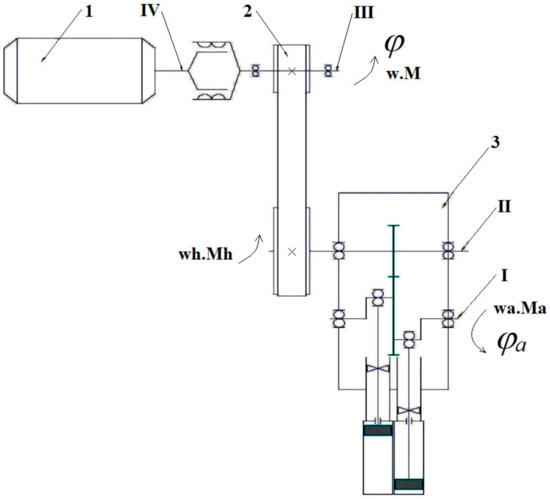
Figure 1.
MPU Flow Chart: 1, pumping power; 2, power transmission; and 3, pump.
To study the moments of forces acting on the transmission shaft, it is important to calculate the power and speed properties of the drive elements. The first stage of the calculation is to refine the output parameters of the electric drive section IV (from the motor to the coupling). It is important to note that the scheme of the drive elements sequence significantly influences the accuracy of the calculation of the power and kinematic properties of the pump unit [12,14]. The drilling rig under study has the following MPU line-up flow chart: motor→open gear→closed gear→coupling→working machine (M→OG→CG→C→WM). Let’s determine the torque of the electric motor as:
where: Pm is motor power (Pm = 30 kW); ωr, rated angular velocity; n, number of revolutions (n = 1500 rpm); and Mdr = ΤΙΙ. Gear module 2, α = 20, β = 6 from 20 to 50 increases torque to 238.7 N∙m.
The driving gear of the transmission shaft of the pump performs the work that drives the pump (drilling rig). Therefore, to reduce energy consumption and improve the reliability of the pump it is necessary to investigate the principle of forces and stresses distribution in the kinematic relations of the gear shaft and gear wheel of the eccentric shaft of the pump [15,16,17,18,19,20]. The power of the gear and wheel was studied when determining the energy components of the pump in the interaction of the transmission and eccentric shafts.
As a result, the dependence of the pump energy costs during drilling was upgraded taking into account the studied moments of forces and accelerations for a given angular rotation velocity ω of the transmission shaft [17,18,19,20,21]:
According to formula (2) Ν1 is mesh gear power; Φτi is the tangent force of inertia; Ri is the shoulder of the force; Ft1 is the force applied to the gear; r1 is the radius of the pitch circle of the gear; n1 is the frequency of the gear rotation; nk is the frequency of the wheel shaft rotation; and Ka is the load factor.
Studies of the principle of the dynamic load effect on the contact surface of the transmission shaft drive gear were carried out step by step, examining how the circumferential, radial, and axial forces in the Ft1 gear change (Table 2).
Table 2.
Change in the forces in the transmission shaft mesh gear.
Analyzing the results obtained, it was found that the change in the value of the action of the circumferential force Ft1 in the mesh gear teeth engagement of the transmission shaft largely depends on the open gear drive. Namely, from the power of the electric drive Pm and its angular velocity ωr, which form the torque ΤII and ΤIII. According to the established dependencies, it is possible to study the operating and operational properties of the drilling rig pump and to estimate the energy intensity of each operation of the core drilling process. The dependence of the torque MK1 on the change in the electric drive operation mode may be expressed through the angular velocity open transmission and described by the equation MK1 = 1.32ω1.006. All of these factors will vary depending on the start-up time t1, braking time t3 and angle α of the tooth mesh corresponding to Δti.
Hence, the circumferential force acting in the mesh gear of the transmission shaft depends on the input properties of the electric motor, which characterize its efficiency. Taking into account that during operation the electric motor operates at relatively stable modes, and the kinematics of shock loads from the drive of the “transmission shaft—gear” system is limited by sliding bearings, the circumferential force in the mesh can be conditionally assumed as Ft1 = const. Studying the influence of the radial Fr1 and axial Fa1 forces on the quantitative values of the mesh force Fm1, dependence on the structural properties (tgα and cosβ) of the kinematic “gear-wheel” system is observed. This dependence can become apparent during the transmission shaft operation.
4. Investigation of the Gear Wear Process with Uneven Distribution of Moments of Forces and Displacement of the Contact Area Relative to the Axis of the Tooth Symmetry
With the natural wear of the gear tooth, the degradation of its contact surface during engagement occurs. With minor wear of the material, the tooth width changes from 1 µm to 1 mm, which leads to a change in the engagement angle tgα, changing the area of the contact surface of the tooth [20,21,22]. As a result of mechanical wear, the deviation of the gearing angle tgα by 1′ significantly changes the action of the radial force Fr1, and changes the vector of its application per unit of the tooth contact area [23,24,25,26,27]. For example, at tgα = 20°, the radial force is Fr1 = 3880.151 N, which ensures effective gearing of the kinematic gear-wheel pair of the pump transmission shaft. With the same mechanical wear, the deviation of the gearing angle is tgα = 19°40′ the value of the radial force Fr1 = 3838.04 N is reduced by 47 N. Wear of the contact surface leads to a change in the structural gaps Δi between the teeth, and under the influence of dynamic moments of forces and angular velocities ω, a dynamic impact occurs in the contact gearing surface. The maximum values of the impact load can be observed at the beginning of the movement and the stop of the gear. This is a short time interval when the element gains acceleration and deceleration corresponding to the times t1 and t2. Local fatigue stress zones are formed by the action of dynamic loads causing microcracks, cracks, and fractures of the teeth. Even the process of partial tooth destruction leads to a distortion of the gearing angle by at least 1°. For example, subject to a partially painted tooth, the gearing angle changes to tgα = 19°, and the radial force changes to Fr1 = 3670.67 N, which is 210 N less than the effective force Fr1 = 3880.151 N. Analyzing the calculations, it can be observed that reducing the forces in the gearing reduces the torque, which ensures effective gearing and operation of the pump. However, operating at a lower torque of the tooth gearing in practice actually shows a progressive degradation of the contact surface, resulting in chipping and breaking off the teeth. This phenomenon can be explained by the fact that the amplitude of the destructive stresses of the material acting on the contact area of the worn surface increases under the action of small moments in the gearing, but in short time intervals t1, t2 = 0.3 s.
When calculating the gear shaft, it is necessary to consider the actual distribution of forces and moments over the entire length of the shaft during operation, taking into account all of its structural elements. In particular, it is necessary to take into account the role of bearings in the effective load distribution in different sections and planes of the studied shaft-gear. To do this, when calculating the forces in the engagement, it is necessary to take into account the degree of influence of the reaction of the forces and moments transmitted from the bearings. This will describe the process of redistributing forces and torques throughout the entire “Bearing-Shaft-Gear-Gear” system under study. From the calculation, it can be seen that if the reaction forces in the bearings are affected, then there is a significant increase in the transverse forces in the vertical and horizontal planes of the gear engagement. If we consider the actual operating conditions of the pump with structural elements of bearings, the values of the same forces are reduced several times from 8100 N to 100 N, which is more consistent with the real load and confirms the effectiveness of the bearings. This means that their action and role in the redistribution of loads is of great importance for the methodology of calculating the loads acting in the gearing and calculating the durability of the gear. If the reaction forces of the bearings are neglected, overestimated numerical values of the load are formed, which will lead to a significant error in the design calculations.
Thus, a scientific problem arises, namely why (with the existing system of distribution of forces and moments in the vertical and horizontal planes) wear is observed in the gear engagement at small values of forces and moments. A theoretical assumption is made that the change in the durability of the gear and the gear wheel is largely influenced not by the magnitude of the acting force and moment, but by its direction vector, which is proposed to be characterized as the coefficient of displacement of the contact spot relative to the designed axis of symmetry.
Therefore, the actual task is to justify the load distribution factors on the gear teeth, taking into account the natural and progressive wear and the acting moments of the reaction forces. In order to study the principles of dynamic load distribution along the transmission shaft during operation, it is necessary to study the formation of stresses on the limited contact surface of the tooth.
Thus, a theoretical assumption that the wear of the contact surfaces of the gear shaft tooth results in the irregular increase in the structural gaps of the gear Δi1, and the shift of the contact spot relative to the symmetry axis of the tooth leads to the increase of stresses acting on a small cross-sectional area, thereby reducing the service life factor.
The design scheme of the shaft is shown in Figure 2.
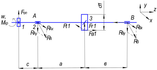
Figure 2.
Design Scheme of the Transmission Shaft: x, y, z are coordinate systems of axes; a, b, c are distances between bearings; d1is the gear diameter; A, B are designations of shaft bearings; w, Mt is the torque; Fct is the cantilever power from belt drive; Ft1, Fr2, Fa1 are the direction of forces on the gear and on the wheel; RA, RAx, Ray, RB, RBx, RBy are the directions of radial reactions in bearings A, B, respectively.
Let’s determine the reactions in the bearings acting in the vertical and horizontal planes (Figure 2). The study of the principle of force reaction distribution along the pump transmission shaft elements shall allow the identification of the most stressed parts of the shaft.
In the vertical plane (3) and (4):
In the horizontal plane (7) and (8):
The results of the calculation show that in the vertical plane, the reaction action of the forces RBy (2) at point (B) of the force application is 83.54 N, and at point (A) RAy = 8006.93 H (3). Such a spread of values can be explained by the action of the torque Mt from the forces of the clear transmission Fog. Consequently, the sections of the shaft in zones 2 and 3 (Figure 3) are subject to the greatest action of dynamic forces, which conditionally tend to shift it relative to the design axis of rotation. This calculation explains the reason for the greatest amount of wear in the gearing, zone 3, the area of application of the radial force Fr1.
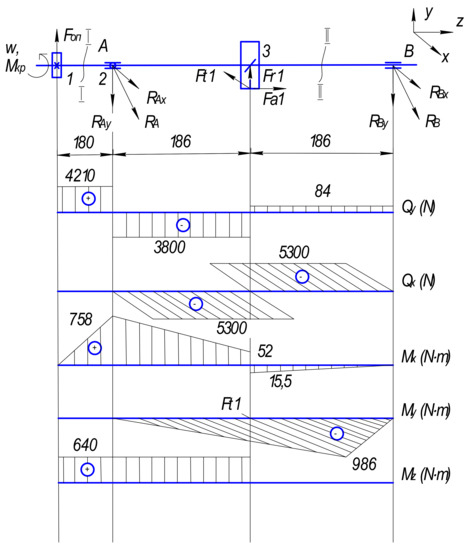
Figure 3.
Design scheme of the shaft with plotting bending and torsional torques: x, y, z are coordinate systems of axes; I, II are shaft sections; A, B are designations of bearings on the shaft; w, Mt is the torque; 1, 2, 3 are shaft sections; Fog is the cantilever force from the belt drive; Ft1, Fr2, Fa1 are the directions of forces on the gear and on the wheel; RA, RAx, Ray, RB, RBx, RBy are the directions of radial reactions in bearings A, B, respectively; Qy, Qx are transverse forces; Mx, My, Mz are bending moments.
In the horizontal plane, the reaction of the forces RAx and RBx equal to 5301 N (8,9) is balanced. This means that in the horizontal plane, in critical zones 2 and 3 and points A and B (Figure 3), the system is in an equilibrium state (Table 3).
Table 3.
Calculated equations of transverse forces and bending moments acting in the transmission shaft.
As a result of tooth wear, the contact spot shifts relative to the axis of its symmetry. The calculation of the reaction of the forces acting in the bearings in the vertical and horizontal planes confirmed the assumption that the displacement of the contact spot leads to a displacement of the center of application of the radial force Fr1 to (Δh/2)-i. This means that the action of the Mt moment shall shift by the value (Δh/2)-i, which will lead to a sharp surge of stresses on the worn part of the tooth.
Plotting the transverse forces in 1–4 cross-sections.
In the vertical plane (10) and (11):
In the horizontal plane (14) and (15):
Plotting bending moments taking into account wear.
Is the vertical plane (relative to the x axis) (16) and (17):
In the horizontal plane (relative to the y axis) (18):
Next, let’s plot the torques taking into account the deviation of the worn area (19):
Let’s determine the total radial reactions in the wear planes (20) and (21):
Let’s determine the total bending moments in the max loaded cross sections (22) and (23):
5. Investigation of the Dependences of the Internal Stress Formation in the Contact Surface of the Wear of the Drilling Pump Transmission Shaft
Localization of concentration zones of internal fatigue stresses during the operation of drilling pumps is a problem in increasing the service life [22,23,24,25,26,27,28,29]. Understanding the principle of fatigue phenomena redistribution in the degraded metal structure during operation will allow effective development of technical solutions for the design and manufacturing technology.
5.1. Determination of Permissible Contact Voltages
The procedure for calculating the permissible contact voltages according to the full algorithm of actions, let’s start with this equality.
Material-40X, improvement; 269-302 HB; σB = 900 MPa sigma time permissible; στ = 750 MPa yield strength of the material; σ−1 = 410 MPa contact stress-destruction.
where: KH, life factor (KH = 1); SH, safety factor; and SH = 1, 1 (for normalization and thermal improvement).
Let’s check the contact stresses on the wear area.
where: f is the auxiliary factor for bevel gears, f = 345 for chevron gears.
where Z2 is the number of teeth of the desired gear, Ugt is the gear ratio. KH2 is the factor considering the load distribution between the teeth. ϑ is the gear rim speed, m/c.
where: KHα = 1.13; factor of load distribution between the teeth; ω is the angular velocity of the wheel, ϑ is the circumferential velocity of the wheel; d2 is the dividing diameter; KHV = 1.06 is the dynamic load factor depending on the circumferential speed of the wheels and the degree of transmission accuracy; and KHβ is the factor of the load unevenness along the tooth length.
(9 degree of accuracy)
5.2. Determination of the Permissible Bending Stresses in the Case of a Worn Surface during Operation
At the second stage of calculations, we will determine the permissible bending stresses for the worn surface during the operation of gears in drilling pumps.
where σFlim is the limit of the teeth endurance along the bending stresses; σFlim = 1.8 HB, σFlim = 1.8σ·285.5 = 513.9 MPa; SF is the safety factor, SF = 1.75; γA is the factor considering the impact of two-way load application; γA = 1 (one-way); γHm service life factor, γH = 1.
Checking the bending stresses of the gear teeth and the wheel.
where: KFα = 1.35, KFβ = 1, KFV =1.12; γF is the factor of the tooth form.
5.3. The Nominal Value of the Maximum Bending Stress in the Worn Part of the Transmission Shaft
The calculation method continues by determining the nominal value of the maximum bending stress in the worn part of the transmission shaft (22):
where W is the axial moment of the resistance of the shaft section, m2 considering the wear of the contact diameter of the tooth cavity.
where is df1 = tooth cavity diameter, mm.
5.4. Nominal Value of the Maximum Tangential Stress (Torsion)
The next step of the strength calculation is the determination of the nominal value of the maximum tangential stress (torsion) (33):
5.5. Let’s Determine the Concentration Factor of Normal and Tangential Stresses for the Calculated Shaft Cross-Sections (37,38)
3 cross-section
where Kσ, Kτ are effective stress concentration coefficients; σB = 900 MPa, σ−1 = 410 MPa; r = 3.5 mm is a bearing chamfer; t = 3.5 mm is a fender height.
where Kd is the coefficient of influence of the cross-section absolute dimensions, Kd = 0.635 (bending for alloy steels + torsion); KF is fatigue strength surface condition factor, KF = 1.50 (Ra 10 ⇒ Rz 40); Ky- fatigue surface hardening factor, Ky = 2.4 quenching with heating of HDPE [σΒ core, 600/800].
5.6. Let’s Define the Criteria and Limits of Endurance in the Calculated Shaft Cross-Sections
To determine the possibilities of the strength resource, we will determine the criteria and limits of endurance in the calculated sections of the shaft, as in Figure 4 and Figure 5 (38):
where σ−1, τ−1 is limits of endurance of smooth samples under a symmetric cycle of bending and torsion (39);
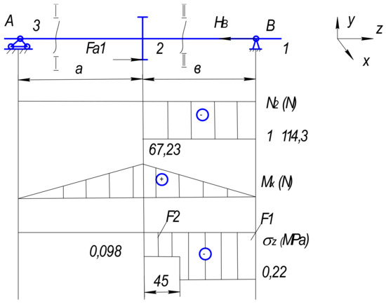
Figure 4.
Design scheme of the shaft with plotting under the action of longitudinal forces: I, II are shaft sections; x, y, z are coordinate systems of axes; a, b are distances between bearings; A, B are designations of bearings on the shaft; 1, 2, 3 are shaft sections; Fog is the cantilever force from the belt drive; Fa1 is the direction of forces on the gear and on the wheel; FB is the direction of force; F1, F2 is cross-sectional area; N2 is longitudinal force; Mx is bending moment; σz is the stress in the corresponding shaft section.
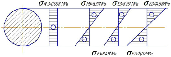
Figure 5.
Design scheme with plotting the highest voltages in the cross section of the shaft: σN3, σM3, σE3, σE2, are stresses in the corresponding shaft cross-sections.
5.7. Plotting under the Action of Longitudinal Forces
5.8. The Greatest Stress in the Cross-Section of the Shaft
Let’s determine the greatest stress in the cross section of the shaft and build a plot.
Cross-section 3, Cross-section 2.
When studying the premature failure of gears due to fatigue chipping, let’s take the maximum stress of crumpling according to Hertz at the elastic touch site (49) as an indicator of the load on the tooth surface:
where zg is the number of gear teeth; ρrr is the reduced radius of curvature; q is the specific contact load; and [σH] is the maximum permissible crumple stress in Hertz.
The maximum Herzian bearing stress at the elastic touch site is represented as (50):
where ZH is the factor considering the longitudinal distribution factor; ZM is the contact strength factor; Zε is the factor considering the influence of the value εα on the load capacity of spur gear; ωHt is the angular velocity of gear wheels; dw1 is the initial diameter of the gear wheel; and u is the gear ratio.
Formulas (2) and (3) indicate that the conditions for the occurrence of critical crushing stresses σH depend on the area of the contact spot formed on the working width bw of the gear ring taking into account the radius ρdr of curvature in the gearing area. It is the area of the tooth contact spot that will limit the circumferential force PHt from the specific contact load acting relative to the diameter dω of the initial circle:
where Pn is the force acting to the normal cross-section; lc is the length of the contact spot, m; KHβ is the load distribution factor across the width of the ring gear; KHυ is the dynamic load factor; and KHα is the factor of load distribution between the teeth.
The long-term operation introduces light surface wear, contributing to the loose fit of the contact surfaces and, as a consequence, the deviation of the design axes of the contact gear (changes in the structure of the mechanism), which causes the redistribution of the load on the teeth surface [15,22,23].
The hardness of the working surfaces was taken as the basis for determining the contact endurance limit and its base number of cycles before destruction. The experience of operating pumps, the results of metallographic examination, and the analysis of the acts of repair and restoration of gears that have failed allowed us to conclude that the surface hardness is not (in most cases) the main cause of failure. When studying the cut of the tooth and its contact surface, the integrity of the coatings is observed, and the grain size and color scheme of pearlite inclusions in the phase structure change from the focus of the load application to the base of the tooth. Rate and moment of fatigue stress formation largely depends on the metal base, its phase composition, and the dispersion of inclusions of martensitic and austenitic grains. Based on the conducted studies, it is proved that the cyclic durability depends more on the value of the applied specific load acting for 1 s.
The action of large moments in a short period of time, for example, when starting up (t1) or braking (t3) the pump transmission shaft (for 0.2–0.35 s), leads to a violation of the critical bending stresses equality σH ≤ [σH]. Violation of this condition causes the teeth of the pivot wheel to break, regardless of the amount of wear. This means that the λ factor of the contact spot displacement from the axis of the design symmetry of the tooth (32) plays a significant role in the formation of moments and affects the assessment of the service life of the mechanism:
where Δi is the deviation of the contact spot from the design axis; and dw and df are the diameters of the initial circle and the circle of the toothed wheel depressions.
It is also essential to evaluate the role of the factor Z2ε, which considers the influence of the value εα on the load capacity of straight gears. More precise factors are set by the obtained polynomial Equation (53):
The most adequate values of the moment considering the contact strength can be determined using the λ factor of the contact spot deviation from the design axis (54):
where [MH1] is the permissible moment; [k0] is the service life factor; and θ is the distribution factor across the tooth.
As established by research, a significant contribution to the change in the value of the effective bending moments is made by the λ factor of deviation from the design axis. More precisely, this property can be described by the dependence (55):
Therefore, it is possible to estimate how the service life factor KHL2 changes, taking into account the influence of the equivalent number NHE of stress cycles, depending on the λ factor for a given surface hardness:
Taking into account the approximation of the data, the number NHE of stress cycles and the λ factor, the equation shall be as follows (57):
Based on the results of the research, a nomogram was developed that determines the dependence of the change in the service life factor and the load distribution factor on the factor of the contact spot deviation from the design axis λ at a given surface hardness (Figure 6).
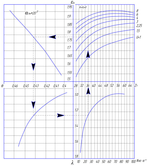
Figure 6.
Nomogram for determining the dependence of the basic cycles of contact stresses from the change in the load distribution factor and the factor of the contact spot deviation from the design axis λ. θ is the coefficient of uneven load distribution along the length of the tooth, and λ is the coefficient of deviation of the contact spot from the design axis of symmetry.
The developed nomogram (Figure 6) allows you to predict the life of the pump without errors, taking into account dynamic loads and operational characteristics of natural wear of the teeth. Analyzing the curves of the graph (Figure 6), it can be seen that with an increase in the value of λ = 1.3 of the coefficient of deviation λ of the contact spot from the design axis of symmetry, the service life of the pump gear engagement decreases sharply to NHO = 25 × 10−4. However, it is observed that changes in the coefficient of deviation of the contact spot λ = 0.9 ÷ 1.1 do not significantly affect the service life of NHO = 60 × 10−4 ÷ 80 × 10−4 cycles, which is the optimal range of strength resource. A sharp degradation of the tooth surface and a decrease in the resource is observed from the values of λ = 1.25. This is explained by the fact that the displacement of the contact spot to λ = 1.25 ÷ 1.3 causes an uneven load distribution along the length of the tooth, as evidenced by the coefficient θ. At the same time, having drawn imaginary perpendiculars according to the graphs (Figure 6), we see how the load distribution coefficient at angular accelerations in different operating modes affects the technical and dynamic parameters of the gear wheel. Thus, the decrease in the wear resistance of the wheel tooth depends not only on the applied force to the area, but also on the degree of displacement of the contact spot at the load distribution coefficient along its length. Moreover, the phase structure of the martensite + perlite base plays an important role in the reliability of the tooth. This structure allows you to withstand high dynamic loads, even with an uneven distribution of forces. The proposed nomogram, in addition to forecasting the resource, allows us to reasonably choose the optimal technological and dynamic parameters of the pump during its operation.
The proposed system approach, which takes into account the formation of stresses depending on the phase structure of the metal and the deviation of the contact spot during the redistribution of a cyclically changing load, will allow more accurately predicting failure.
6. Simulation, Experimental 3D Loading of Gears for Verification and Confirmation of Theoretical Research Results
In order to obtain adequate research data using the SOLIDWORKS software, a loading scheme was clearly developed in which torque was applied through the shaft to the drive gear and the meshing ring. To simulate the loading of kinematic pairs of engagement, the Static II Pro submodule of the SOLIDWORKS software with the GearTrax application was used. When developing the loading scheme, to identify the input parameters, the main characteristics were set: the type of gear support (cylindrical support) and the possible degrees of freedom that determine the directions of the applied engagement forces, accelerations, etc.
Based on the calculations of the geometric characteristics, power and strength calculations, a model of interaction of the kinematic pair “the drive gear of the transmission shaft—driven of the eccentric shaft” in the form of assembly units was obtained, which will qualitatively and quantitatively characterize the picture of the load distribution over the contact surface of the kinematic pair of gearing of the rotary platform reducer (Figure 7).
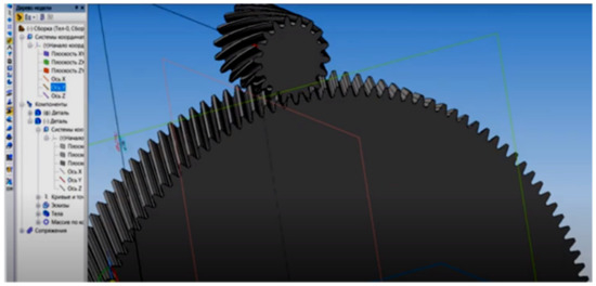
Figure 7.
Element-wise modeling of a pair of gearing.
In addition to quantitative characteristics, we also determined qualitative indicators. Let us set the applied load in the contact patch at the base of the tooth cavity up to its pitch diameter. The places subject to the greatest stress are indicated by the color spectrum.
The origin of contact and bending stresses on the gear rim of the eccentric shaft is small, but the depth of propagation and the color spectrum of the spectral diagram allow us to conclude that the transmission shaft with the gear works under conditions of large alternating loads occurring in a short period of time (Figure 8). The concentration of critical stresses has a local character and is short in time. The color scale characterizes the contact area of the gear operating with stresses σF = 68,347 ÷ 123,025 MPa. This load mode proceeds within the permissible limits under the condition of strength σF ≤ [σF].
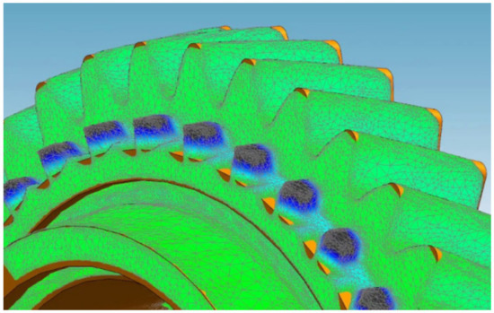
Figure 8.
Load distribution on the contact surfaces of the teeth.
Spectral analysis of the drive gear of the transmission shaft of the pump showed that with equidistant engagement, the load and forces are distributed evenly over the contact surface of the tooth. Normal stresses are also distributed at the base of the tooth without going beyond the critical values of the durability coefficient. However, at the same effective load, but with the deviation of the contact spot in the engagement from the design axis of symmetry, the stresses increase both at the crown of the tooth and at the base. Critical stress distribution zones are shown in yellow and red (Figure 8). This process confirms the satisfactory convergence of the effect of the proposed contact spot displacement coefficient on the service life of the gear when the design axis of the wear spot symmetry is shifted.
When the gear is turned, the torque from the transmission shaft is transmitted through the meshing of the teeth to the driven gear. Accordingly, the action of the forces of resistance and the forces of inertia of its own masses will primarily affect the drive gear. Pump accelerations and angular speeds reach peak values during acceleration and deceleration. In the period t1 (acceleration time during the operation of the mud pump), the initial stage of interaction of the engagement pair occurs and the internal stresses σF and σH sharply increase. This period corresponds to the contact of two rolling toothed surfaces at a given force of 20 kN with stresses σF = 68,347 − 123,025 MPa. The load will reach its maximum value during the final engagement period t3. During braking, forces and a moment of inertia are added to the torque to exert pressure on the contact surface area. The magnitude of pressure is progressively increasing. Maximum stress values arise, tending to disrupt the power balance and deform the geometry of the tooth (Figure 9).
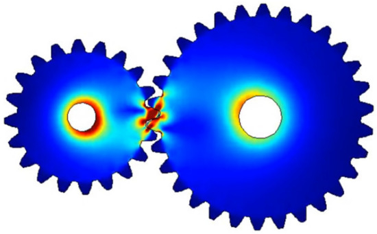
Figure 9.
Zones of maximum stress concentration when rotating the turntable.
Next, we investigate the distribution of stresses in the teeth of the drive gear. The first power disturbances are transmitted to the shaft at the base of the gear. This is also evidenced by the red color of the spectrum (Figure 10).
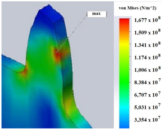
Figure 10.
Localization of internal stresses at a given load.
Further, the stresses are transmitted to the working surface of the tooth. When the maximum values of stresses are reached, structural breakdown of the metal occurs and, as a result, fatigue deformation and fracturing occurs. With an uneven distribution of the load over the displaced contact patch caused by fatigue stresses that increase in a short period of time, the fracture zone of the material surface increases along the length of the deceleration path (Figure 10). The traversed path of the drive gear at the moment of braking is accompanied by a slow rolling of the teeth (i.e., a decrease in the contact area with increasing voltage (Figure 10)).
It is this moment that is critical, since the condition of equilibrium of the balance of forces and acting stresses of contact and bending is violated. The investigated processes explain the nature of the fracture of the teeth on the gear rim of the eccentric shaft. Fractures, as a rule, occur in the same zone, corresponding to the maximum operating range of the gears at the moment of braking the drill and the pump.
The presented results of modeling the process of engagement of the kinematic pair “drive gear of the transmission shaft—driven eccentric shaft” indicate the high energy consumption of the transmission shaft of the mud pump. The force and strength analysis of the interaction of the contact surfaces of the engagement with the classical arrangement of the mechanism showed the zones of a dangerous section, on which the concentration of bending and contact stresses is localized. A high level of stress values concentrated in the contact spot of the engagement reaches critical values at some time intervals ∆ti (i.e., the conditions of strength σи > [σи] are violated), which leads to the destruction of the metal under cyclic loads and, as a consequence, the flaking of the teeth. Critical values of stresses arise at the moment of deceleration of the pump and drill, which occurs at the maximum value of the zenith angle of drilling α = (35 ÷ 60)°. The obtained values of forces and stresses in a pair of engagement during modeling are in satisfactory agreement with theoretical calculations and reveal the essence and nature of the appearance of tooth breakage at a certain mode of the time interval ∆t3.
Analyzing the results of the research carried out, we can draw the following conclusions:
- -
- The distribution of the load over the contact surface of the kinematic pair of engagement is uneven and inconsistent in time;
- -
- Due to the prevailing torques, the gear rim of the transmission shaft is a more loaded part;
- -
- The hardness of the tooth surface does not play a decisive role in the durability of the mechanism. The most significant factor is the factor that determines the number of working cycles (resource), namely the degree of uniformity of the distribution of forces in the critically extreme periods of acceleration t1 and deceleration t3 with an increasing value of the moment of inertia.
The results of theoretical and laboratory studies of simulation models confirm that one of the more effective methods for increasing the durability and energy efficiency of the rotary mechanism is the timely redistribution of forces in the engagement.
7. Discussion of the Displaced Spot of the Contact Surface Wear
The influence of the misalignment of the axes on the work of the kinematic gearing pair was studied along with the process of teeth load distribution. To calculate the gearing pair, the superposition method was used considering the presented factors separately.
Thus, the proposed mathematical model of load distribution along the tooth surfaces of the kinematic pair of “transmission shaft driving gear—eccentric shaft rim gear” can more accurately assess the impact of the factor of the λ contact spot deviation from the design axis on the service life of the mechanism. As established by research, the λ factor significantly affects the value of the moment that occurs in the gearing, and therefore shall characterize the power spent by the gearbox of the rotary platform to overcome the resistance forces.
With an increase in the wear asymmetry in the contact spot, the energy intensity of the drilling process also increases, which means that the equation describing the gear power in the gearing and the distribution of the bending moment will be as follows (58):
where Ng, gear engagement power; φτi, tangential force of inertia; Ri, force application shoulder; Fg, the force applied to the gears; rg, the radius of the dividing circle of the gear; ng, gear rotation speed; nk, speed of rotation of the gear wheel; Ka, a coefficient that takes into account the impact of the load, [MH1], acceptable moment; [Ko], a coefficient that takes into account the durability; θ, coefficient of uneven load distribution along the length of the tooth, bω, working width of the tooth; and dω, diameter of the initial circle of the gear wheel.
The proposed method for calculating the service life of the mechanism crown teeth, as well as the established relationship between the value θ (60) and the values zg and λ, allows for considering the impact of external loads and the axial displacement of the contact spot when calculating the bending moments. As can be seen from the Equation (33), the greater the λ and θ factors are, the greater the MH1 values is. It was determined that the load distribution on the gear teeth during the displacement of the gearing axes occurs unevenly and at different speeds. Increasing the deviation of the contact spot from the design axis increases the energy intensity of the drilling process by 17–42%.
The proposed method allows the determination of the dependence of the basic operation cycles with variable loads NHO on λ and θ. For a more accurate determination of fatigue stresses, along with dynamic loads, it is necessary to take into account the physical and mechanical properties of the material (HB or HRC hardness). The calculations showed the greater the λ and M1, the greater the wear i and the higher the probability of tooth breakage.
When determining the dependence of the service life factor K2 HL on the bending stress, the following methods were used: A. S. Pronikov’s theory of the transition from one type of interaction to another, h/r ≥ Ko (c·σT/E)2; transition from elastic deformation to fracture, σx = 0.33 HB/1 − ψ; P.F. Dunayev’s theory; [σ]H = (1.8 HB + 67)/1.1 or [σ]H = (14 HRC + 170)/1.1, here [σ]H describes the permissible contact-surface stress, and the 1.1 factor describes the margin of safety [22,23,24,25,26,27,28,29,30,31,32].
The dependence of λ on the contact bending stresses σ and—equation (32) [32] was obtained taking into account the above-mentioned theories of contact surfaces interaction and the method developed by the author.
8. Conclusions
The power Ng of the gearing of the drive transmission shaft gear and the eccentric shaft gear, which characterizes the energy consumption of the drill bit depth stroke, was determined.
The established ratios of the studied indicators shall help to develop a set of measures to reduce the influence of external inertia forces and to optimally redistribute the load in the gearing during drilling at the angle φ without loss of power in the gearing, especially in the critical time interval ti.
The proposed method of calculating the load of the kinematic pair of the drilling unit pump gearing allowed taking a broader look at the problem of the energy intensity of the drilling operation. For example, GOST 16162-78 regulates determining the limit of contact endurance by the hardness of the working surfaces. The contact stress base is also taken as a function of the average hardness.
This condition does not fully determine the cycle base that corresponds to the achievement of critical values of contact stresses at the maximum service life. This discrepancy can be confirmed by the fact that the transmission shaft with external gearing is made of 40X steel (GOST 1050-74) after heat treatment, provided by the manufacturing technology with the hardness of the active teeth surfaces of 30–35 HRC. The drive gear is made of 40X steel (GOST 4543-71), and the surface hardness is 260 HB (GOST 8479-70). The specified hardness is high enough to withstand significant loads. According to the manufacturing technology, only the upper layers of the metal are quenched or cemented, since it is the surface that must have high physical and mechanical properties, and the metal base must be viscous (load damper). However, with such high physical and mechanical properties of the surfaces in the practice of operating pumps, the breakage of the teeth of the transmission shaft is quite common.
As shown by theoretical studies conducted according to the proposed method, a significant role in the service life of the mechanism is played not by the hardness of the surfaces, but by the concentration of forces applied to the contact area per unit of time. It is the magnitude of the applied force per second of time per contact area that forms the stress concentration zones. The localization of fatigue stresses over time exceeds the limit of possible bending stresses and the fluidity of the metal, which leads to the destruction of the tooth.
Author Contributions
Conceptualization, formulation and research of scientific hypotheses and project administration V.V.S.; methodological component, formal analysis and writing—original draft preparation S.N.K.; data curation and reviewing A.V.S.; software study of strength calculation O.V.I.; validation and reviewing P.V.; analytics, editing, graphic drawing Z.Z.Z. All authors have read and agreed to the published version of the manuscript.
Funding
This work was supported by a publications grant of the Gheorghe Asachi Technical University of Iasi (TUIASI), project number GI/P6/2021.
Institutional Review Board Statement
Not applicable.
Informed Consent Statement
Not applicable.
Data Availability Statement
All required data are provided in the article.
Conflicts of Interest
The authors declare no conflict of interest.
References
- Pachurin, G.V.; Filippov, A.A.; Goncharova, D.A.; Kuzmin, A.N.; Gevorgyan, G.A. Fatigue of structural materials in corrosive environments. Sci. Tech. Prod. J. Vestn. Mashinostroeniya 2020, 117, 78–84. [Google Scholar]
- Lin, H.; Bergadà, J.M.; Zeng, Y.; Zhang, Y.; Wang, J. Rotor spinning transfer channel design optimization via computational fluid dynamics. Text. Res. J. 2018, 88, 1244–1262. [Google Scholar] [CrossRef]
- Tikhonov, V.S.; Baldenko, F.D.; Bukashkina, O.S.; Liapidevskii, V.Y. Effect of hydrodynamics on axial and torsional oscillations of a drillstring with using a positive displacement motor. J. Pet. Sci. Eng. 2019, 183, 257–265. [Google Scholar] [CrossRef]
- Feng, Z.-M.; Guo, C.; Zhang, Y. Variable speed drive optimization model and analysis of comprehensive performance of beam pumping unit. J. Pet. Sci. Eng. 2020, 49, 152–163. [Google Scholar] [CrossRef]
- Brijesh, R.N.; Sagar, M.P. The Effect of Venturi Design on Jet Pump Performance. J. Res. 2016, 2, 23–28. [Google Scholar]
- Savinkin, V.V.; Vizureanu, P.; Sandu, A.V.; Ratushnaya, T.Y.; Ivanischev, A.A.; Surleva, A. Improvement of the turbine blade surface phase structure recovered by plasma spraying. Coatings 2020, 10, 62. [Google Scholar] [CrossRef]
- Khaing, H.; Lwin, Y.M.; Lwin, Y. Design and Calculation of Centrifugal Pump (Impeller) For Water Pumping. Int. J. Sci. Eng. Technol. Res. 2019, 28, 321–324. [Google Scholar]
- Vetter, S.; Leidich, E.; Hasse, A. Probability of mine survival. In Proceedings of the Nodal Connections, the 18th International Conference on New Trends in Fatigue and Fractures of Any Scale, (ICIE 2018), IDMEC Instituto de Engenharia Mecanica, Lisbon, Portugal, 20 July 2018; pp. 225–228. [Google Scholar]
- Neikes, K.; Schlecht, B.; Vetter, S.; Leidich, E. Untersuchungen zum Einfluss von Mittelspannungen auf die Ermüdungsfestigkeit von Wellen und Achsen (Investigations into the Influence of Medium Stresses on the Fatigue Strength of Shafts and Axles); Final report no. FVA-Нет. 321 VI, 1321 г.th ed; Frankfurt am Main, Germany, 2019; Volume 16, p. 157. [Google Scholar]
- Baldenko, D.F.; Baldenko, F.D. Wheel Tooth Profiles of Hydraulic Machines and Mechanical Gears: Traditions and Innovations. Glob. J. Res. Eng. A Mech. Mech. Eng. 2020, 20, 211–219. [Google Scholar]
- Lyagov, I.A.; Baldenko, F.D.; Lyagov, A.V.; Yamaliev, V.U.; Lyagova, A.A. Methodology for calculating technical efficiency of power sections in small-sized screw downhole motors for the «perfobur» system. J. Min. Inst. 2019, 240, 694–700. [Google Scholar] [CrossRef]
- Sheha, A.A.; Nasr, M.; Hosien, M.A.; Wahba, E.M. Computational and experimental study on the water-jet pump performance. J. Appl. Fluid Mech. 2018, 117, 1013–1020. [Google Scholar] [CrossRef]
- Kyznetsova, V.N.; Savinkin, V.V.; Ratushnaya, T.Y.; Sandu, A.V.; Vizureanu, P. Study of the spatial distribution of forces and stresses on wear surfaces at optimization of the excavating part of an earthmoving machine transverse profile. Coatings 2021, 182, 1–16. [Google Scholar]
- Barsoum, I.; Khan, F.; Barsoum, Z. Analysis of the torsional strength of hardened splined shafts. Mater. Des. 2014, 54, 130–136. [Google Scholar] [CrossRef]
- Kuznetsova, V.N.; Savinkin, V.V. More Efficient Rotation of Excavator Platforms. Russ. Eng. Res. 2017, 37, 667–671. [Google Scholar] [CrossRef]
- Gorlenko, A.O.; Davydov, S.V.; Shevtsov, M.Y.; Boldyrev, D.A. Wear-Resistance Increase of Friction Surfaces of Steel Machine Parts by Electro-Mechanical Hardening. Mech. Eng. Metallurg. Steel Transl. 2019, 49, 800–805. [Google Scholar] [CrossRef]
- Jeong, H.S.A. Comparative Study on the Equation of Motion about Models of Variable Displacement Piston Pump through MATLAB & DAFUL. Mach. Complexes 2016, 12, 75–76. [Google Scholar]
- Burov, A.; Bazbetov, A.; Ponomarev, N.; Sapozhnikov, M. Recalculation of the loading mode of drilling pumps of single and double action is made: Oil-producing equipment and complexes. In Proceedings of the Volgograd State Technical University, Volgograd, Russia, 22 February 2019; pp. 74–77. [Google Scholar]
- Koleda, E.V.; Kireev, S.O.; Korchagina, M.V.; Efimov, A.V. Determination of reactions in the crank shaft supports of the drive part of the high-pressure pump. In Proceedings of the 13th International Scientific and Practical Conference (State and Prospects of Development of the Agro Industrial Complex) In the Framework of the XXIII Agroindustrial Forum of the South of Russia and the Exhibition Interagromsh, Don State Technical University, Rostov-on-Don, Russia, 25 June 2020; pp. 605–609. [Google Scholar]
- Kadhimm Zarzoor, A.; Almuramady, N.; Hussein, E.S. Stress analysis for spur gears using solid works simulation. Int. J. Mech. Eng. Technol. 2018, 259, 927–936. [Google Scholar]
- Savinkin, V.V.; Kuznetsova, V.N.; Ratushnaya, T.Y.; Kiselev, L.A. Method of integrated assessment of fatigue stresses in the structure of the restored blades of CHP and HPS. Bull. Tomsk. Polytech. Univ. Geo Assets Eng. 2019, 330, 65–77. [Google Scholar]
- Savinkin, V.V. Development of the Theory of Energy Efficiency of Single-Bucket Excavators; Siberian State Automobile and Road University: Omsk, Russia, 2016. [Google Scholar]
- Savinkin, V.V.; Kuznetsova, V.N. Investigation of the influence of the displacement of the contact spot of engagement on the durability of the crown of the rotary wheel of the excavator. In Scientific, Technical and Industrial Journal: Scientific Peer-Reviewed Journal “Construction and Road Machines”; Publishing House of Technical Literature SDM-Press: Moscow, Russia, 2017; Volume 1, pp. 12–15. [Google Scholar]
- Xiaofeng, Q.; Jie, L.; Xingguo, Z.; Li, F.; Ruiqiang, P. Fracture failure analysis of transmission gear shaft in a bidirectional gear pump. Eng. Fail. Anal. Mach. Reliab. 2020, 118, 138–141. [Google Scholar] [CrossRef]
- Rossetti, A.; Macor, A.; Scamperle, M. Optimization of components and layouts of hydromechanical transmissions. Int. J. Fluid Power 2017, 318, 123–134. [Google Scholar] [CrossRef]
- Das, S.; Nayak, B.; Sarangi, S.K.; Biswal, D.K. Condition Monitoring of Robust Damage of Cantilever Shaft Using Experimental and Adaptive Neuro-fuzzy Inference System (ANFIS). Technol. Eng. 2016, 144, 328–335. [Google Scholar] [CrossRef][Green Version]
- Xiang-Yu, Y.; Shi-Jeng, T. Computerized method for analyzing the contact of loaded teeth of spur gears with a high contact ratio with or without modification of the side surface, taking into account the angular contact of the tip and shaft misalignment. Theory Mech. Mach. 2016, 97, 190–214. [Google Scholar]
- Tan, J.-J.; Hu, Z.-H.; Wu, L.-J.; Feng, Z.H.; Song, C.S. Influence of Geometric Design Parameters on Static Strength and Dynamics of Spiral Bevel Gears. Int. J. Rotating Mach. 2017, 148, 211–223. [Google Scholar]
- Pronikov, A.S. Parametric Reliability of Machines M.; Publishing House of Bauman Moscow State Technical University: Moscow, Russia, 2002; p. 560. [Google Scholar]
- Danube, A.V. Non-Traditional Tribology. In The Modification of the Surfaces of Friction; Lamdert Academic Publishing: Sunnyvale, CA, USA, 2013; pp. 270–281. [Google Scholar]
- Ren, Y.; Chang, S.; Liu, G.; Wu, L.; Lim, T.S. Impedance Synthesis Analysis of Gear Train Vibration. Shock. Vib. 2017, 214, 425–438. [Google Scholar]
- Van der Linden, F.L.J. Modeling Gear Positioning Systems: An Object Oriented Model of Gear Contact with Validation. J. Mech. Eng. Sci. 2016, 230, 1084–1100. [Google Scholar] [CrossRef]


Publisher’s Note: MDPI stays neutral with regard to jurisdictional claims in published maps and institutional affiliations. |
© 2021 by the authors. Licensee MDPI, Basel, Switzerland. This article is an open access article distributed under the terms and conditions of the Creative Commons Attribution (CC BY) license (https://creativecommons.org/licenses/by/4.0/).