Review

Geotechnical Design Practices and Soil–Structure Interaction Effects of an Integral Bridge System: A Review

School of Engineering, Design and Built Environment, Western Sydney University, Sydney 2747, Australia
*
Author to whom correspondence should be addressed.
Appl. Sci. 2021, 11(15), 7131; https://doi.org/10.3390/app11157131
Submission received: 6 July 2021 / Revised: 27 July 2021 / Accepted: 29 July 2021 / Published: 2 August 2021
(This article belongs to the Special Issue Advances in Geotechnologies in Infrastructure Engineering)

Abstract

:
Integral bridges are a class of bridges with integral or semi-integral abutments, designed without expansion joints in the bridge deck of the superstructure. The significance of an integral bridge design is that it avoids durability and recurring maintenance issues with bridge joints, and maybe bearings, which are prevalent in traditional bridges. Integral bridges are less costly to construct. They require less maintenance and therefore cause less traffic disruptions that incur socio-economic costs. As a consequence, integral bridges are becoming the first choice of bridge design for short-to-medium length bridges in many countries, including the UK, USA, Europe, Australia, New Zealand and many other Asian countries. However, integral bridge designs are not without challenges: issues that concern concrete creep, shrinkage, temperature effects, bridge skew, structural constraints, as well as soil–structure interactions are amplified in integral bridges. The increased cyclic soil–structure interactions between the bridge structure and soil will lead to adverse soil ratcheting and settlement bump at the bridge approach. If movements from bridge superstructures were also transferred to pile-supported substructures, there is a risk that the pile–soil interactions may lead to pile fatigue failure. These issues complicate the geotechnical aspects of integral bridges. The aim of this paper is to present a comprehensive review of current geotechnical design practices and the amelioration of soil–structure interactions of integral bridges.

1. Introduction

Traditionally, bridges are designed and constructed with expansion joints and bearings to accommodate the expansion and contraction of the bridge due to temperature and stress changes. However, expansion joints and bearings need regular maintenance and replacement due to cyclical deck movement, traffic loading, trapped debris, and salt and moisture intrusion [1,2]. Degradation of expansion joints is a persistent cause of costly maintenance and rectification work [3]. Failure to maintain the bridge joints and bearings could cause overstress and structural distress in the bridge structure, which must be avoided. Rectification work is often disruptive to traffic flow and causes an increase in travel time that also incurs socio-economic costs for road users. Although conventional or jointed bridges still outnumber integral bridges, the overall trend of bridge construction towards integral bridges is increasing to avoid the recurring maintenance issues related to bridge joints and bearings.
Integral bridges have been used since 1938 in Ohio, the United States of America (USA) [4]. During the construction boom of the National Interstate Highway System, in the late 1950s and mid-1960s, several USA states began to use integral bridges as a construction choice for bridges. In 1980, the American Federal Highway Association (FHWA) recommended bridges to be constructed as integral bridges for steel bridges with overall lengths up to 90 m, cast-in-place concrete bridges up to 150 m and post-tensioned bridges up to 183 m [5]. According to Tabatabai et al. [6], approximately 70% of the USA State Department of Transportation (DOT) have already included integral bridges in their jurisdictions. In 1996, the British Highway Agency recommended adopting an integral bridge design approach for any bridge with a length of up to 60 m [7]. Integral bridges in other regions and countries, e.g., Europe, Japan, Canada, China and Oceania, also witnessed rapid development in the last few decades.
Under cyclic thermal, environmental and mechanical loading, the bridge superstructure expands and contracts. Movements particularly in the bridge deck of integral bridges will cause the bridge abutment to displace directionally into and away from the approach fill with each cycle. The movements of the abutment and substructure mobilise significant soil–structure interaction (SSI) effects [8,9,10,11], such as stress variations, soil densification, stress ratcheting [12,13,14], heave, settlement and/or slumping of the backfill soil [15,16], which in turn affect the overall performance of integral bridges. Stress ratcheting is the phenomenon that increases the lateral earth pressure applied on the abutments due to cyclic movements transferred from the bridge deck [12]. Pile-supported systems will also be affected by the abovementioned issues of integral bridge. The repeated actions of deck movements, much of which is induced by temperature changes, may be transferred to the piles, changing the soil properties around the pile. Many researchers have reported that the overall pile–soil interaction is dependent on various factors including pile type, pile orientation, pile flexibility, soil properties around piles and substructure stiffness [17,18,19,20]. Cyclic displacements and moments transferred to pile foundations are at risk of causing pile fatigue failure [21]. The complexities associated with pile–soil interaction ultimately affect the overall performance of the integral bridge including the bridge approach. Despite this, Philip [22] reported that only two states in the USA consider the pile stress due to thermal movements, while other states neglect this aspect in the integral bridge design.
It is quite evident from literature that different countries and jurisdictions are using a variety of design guidelines and practices to deal with the geotechnical issues for abutments and pile foundations. Therefore, this paper aims to present a comprehensive review of the design guidelines and the literature relevant to the recommended practices corresponding to the geotechnical aspects of integral bridges incorporating the effects of SSI. In the literature, a variety of definitions and terminologies have also been used to describe integral bridges. This can sometimes cause confusion to the reader. Hence, this paper begins with a discussion on different terminologies and definitions used for integral bridges to establish the context for the review.

2. Terminologies and Definitions of Integral Bridges

The diversity in design and construction of integral bridges created various terminologies and definitions. The type of design and construction ultimately has ramifications on the geotechnical aspects of integral bridges. According to the widely accepted definition used by bridge engineers, an integral bridge is one where the bridge deck is without any expansion or contraction, and they can be sub-categorised as an integral abutment bridge (IAB) or a semi-integral abutment bridge (SIAB). A bridge with a fully continuous or integral connection between the deck and the abutment is defined as an IAB. In the literature, IABs are also referred to as fully integral abutment bridges (FIABs). The SIAB, like the IAB, has a continuous deck without joints, but with bearings between abutments and the bridge deck, such that the superstructure is not continuous or monolithic with the abutments. It is noted that the terms IAB and SIAB are quite extensively used in North America.
The American Association of State Highway and Transport Officials (AASHTO) Load and Resistant Factor Design (LRFD) Bridge Design Specifications [23] offers a slightly different definition. According to AASHTO, an integral bridge is a bridge without deck joints having integral abutments that are rigidly attached to the superstructure and supported on a spread footing or pile foundation designed to resist and/or absorb creep, shrinkage, and thermal deformations of the bridge superstructure. This definition is analogous to that of an IAB as defined in the paragraph above. SIAB unfortunately does not fit into this definition. The AASHTO does not further sub-classify integral bridges, although most of the states in the USA have included design guidelines for different sub-classes of integral bridges in their design manuals.
In European countries, integral bridges are commonly defined as either fully integral bridges or semi-integral bridges [24]. Integral bridges are defined based on the connection between the continuous deck and abutment. There are no expansion joints and bearings in fully integral bridges, and this is analogous to the definition adopted by others for IABs. In the same way, semi-integral bridges are analogous to the definition of SIABs.
PD 6694-1 [25], published by the British Standards Institution (BSI), defines an integral bridge as a continuous bridge (continuous deck without any joints), which accommodates expansion and contraction of the bridge deck by the movement of the abutments in and out of the backfill. It also classifies the types of integral and semi-integral abutments for the integral construction of the integral bridges. PD 6694-1 categorises three types of abutments for integral construction: full height frame abutments as shown in Figure 1a–c, embedded wall abutment as shown in Figure 1d, and end screen abutments as shown in Figure 1e–i.
The movements in full height frame abutments are accommodated by rotation or flexure of the abutment wall—whereas, in end screen abutments, the abutments can translate in and out of the fill to compensate for the deck movements. PD 6694-1 [25] provides further sub-classifications for end screen abutments: bank pad abutments including those supported on the ground or piles as shown in Figure 1e–g, flexible support abutments as shown in Figure 1h, and semi-integral abutments as shown in Figure 1i. According to PD 6694-1 [25], semi-integral abutments consist of the movement bearings at the connection between the vertical support at the end of the bridge deck and conventional or embedded walls or reinforced soil abutments. The movement bearing connection accommodates the deck expansion and contraction without transferring the effect to the bridge abutment.
As it may be observed, the various definitions used in North American and European practice do not map entirely onto each other and may thus cause ambiguity in some cases. To avoid ambiguity, this paper is written in terms of integral bridge and those of its two major subcategories, namely IAB and SIAB, as defined in the first paragraph of this section.

3. Geotechnical Guidelines and Practices for the Design of Integral Bridges

The design standards and practices with respect to the types of abutments, design limitations of integral bridges, and design consideration and mitigation measures concerning geotechnical requirements of integral bridges are reviewed in this section. The review focusses on the countries of USA, UK, Canada, Japan, Spain, Switzerland, Sweden, Finland, Australia, and New Zealand.

3.1. USA Practices

The USA is the first country that utilised integral bridges on a large scale. According to Tabatabai et al. [6], approximately 65% of the States Department of Transportation (DOTs) prefer IABs over traditional bridges, whereas one state (Arizona) prefers SIABs. However, the USA practices still produce significant variations in the design guidelines among different states.

3.1.1. AASHTO LRFD Bridge Design Specification

The AASHTO LRFD Bridge Design Specification [23] provides guidelines concerning the design of bridges including the calculations of earth pressures behind the bridge abutments. Article 11.6.1.3 of LRFD Design Specification [23] specifies that integral abutments should account for shrinkage, creep and thermal deformations of the superstructure. Lateral pressure calculations for integral abutments are generally based on the lateral earth pressure coefficients: K 0 for the at-rest condition, K a for the active condition and K p for the passive condition. Methodologies used to calculate these lateral earth pressure coefficients are discussed in the AASHTO LRFD Specification [23]. The coefficient, K 0 , is calculated using the well-known Jaky’s formula [26] for normally consolidated soil and Mayne and Kulhawy’s formula [27] for over-consolidated soil. The coefficient, K a , is calculated based on the Coulomb wedge theory. It further recommended that, when Coulomb’s theory is not suitable, the active earth pressure can be estimated using the trial procedures based on Culmann’s wedge theory [28].
The AASHTO LRFD Specifications [23] refer to the graphs developed by the U.S. Department of Navy [29] to determine the coefficient K p for the case of a sloping or vertical wall. However, for conditions that deviate from those described by the U.S. Department of Navy [29], it recommends using Terzaghi’s log spiral wedge theory [28] to determine the magnitude of K p . Although the mobilised earth pressure depends on the expansion/contraction of the bridge superstructure, the AASHTO LRFD Specification only provides guidance on approximate values of abutment displacement required to fully mobilise active or passive earth pressure. It does not provide explicit guidelines on the following aspects:
  • Calculations of K p when the movement is more than zero but less than the movement required to fully mobilise passive and/or active pressure; however, some USA states use linear interpolation to estimate the mobilised earth pressure for such cases;
  • The abutment displacement ( ) is taken as the displacement at the top of the abutment regardless of whether the mode of movement is rotational, translational or a combination of both;
  • The values of fully mobilised displacements are based on a study conducted by Clough and Duncan [30] under monotonic loading. However, the abutment–soil interaction in integral bridges involves cyclic loading, which almost certainly differs from the monotonic loading case.

3.1.2. Practices in USA States

The consideration of the design loads that emerged from the lateral earth pressure acting on the abutment of integral bridges in the USA varies from state to state. In fact, there is no single approach in the USA to address this point, notwithstanding the availability of the AASHTO [23] guidelines. The DOTs rely primarily on previous experience and, in a few cases, on data from in-service bridges to develop their design methodologies.
Most of the USA states have defined and discussed the integral and semi-integral abutment as the two types of abutment in integral bridges. Here, integral abutment refers to an abutment of an IAB, while semi-integral abutment refers to an abutment of an SIAB. Alaska has discussed only the SIAB [31], while Idaho [32] and North Dakota [33] have discussed only the IAB in their design manuals. Virginia [34] and Maine [35] have used the term “full integral abutment” instead of “integral abutment”.
The recommended limiting design criteria for the design of integral bridges in the different states, such as length of the bridge, the bridge’s skew angle, and the preferred type of abutment foundation, vary from state to state. Most of the states have recommended IABs as the first design choice of the bridge and SIABs as a second choice only if the design requirements exceed the limiting design criteria of IABs. Some states, such as Ohio, also emphasized the choice and design of integral bridge based on the foundation requirements [36]. Ohio prohibited the integral abutment from being placed on mechanically reinforced earth (MSE), and spread footing is recommended for the semi-integral abutment [36].
The magnitude of the thermal movements of the integral bridge directly relates to the temperature changes in that region. Therefore, the maximum allowable length of the integral bridge should depend on the weather conditions in the state. As such, the maximum allowable length of the integral bridges is not uniformly standardized in the design guidelines of the states. Very few states, in fact, have provided the design criteria for the design of integral bridges based on maximum allowable abutment displacement, such as provided by Utah [37] and Oregon [38]. New Jersey [39] has provided the expansion length of the bridge as limit criteria to limit the construction of integral bridge, whereas Ohio [36] has provided both expansion length and total bridge length as limit criteria. Not all the states (e.g., Alaska [31]) have recommended considering the thermal effects on lateral earth pressure in the design of integral bridges. Some states (e.g., Ohio [36], Utah [37] and Massachusetts [40]) have provided the equations to calculate the design earth pressure distribution behind the abutment of IABs and SIABs based on abutment displacement. However, most states are still using the traditional earth pressure theories (e.g., Rankine or Coulomb earth pressure theory), which were developed specifically for the retaining structures under monotonic loadings. The necessity of the SSI analysis for the design of integral bridges has been recommended in only a few states. Even in states that have recommended SSI analysis (e.g., Virginia [34] and Massachusetts [40]), the guidelines on SSI are not comprehensive.
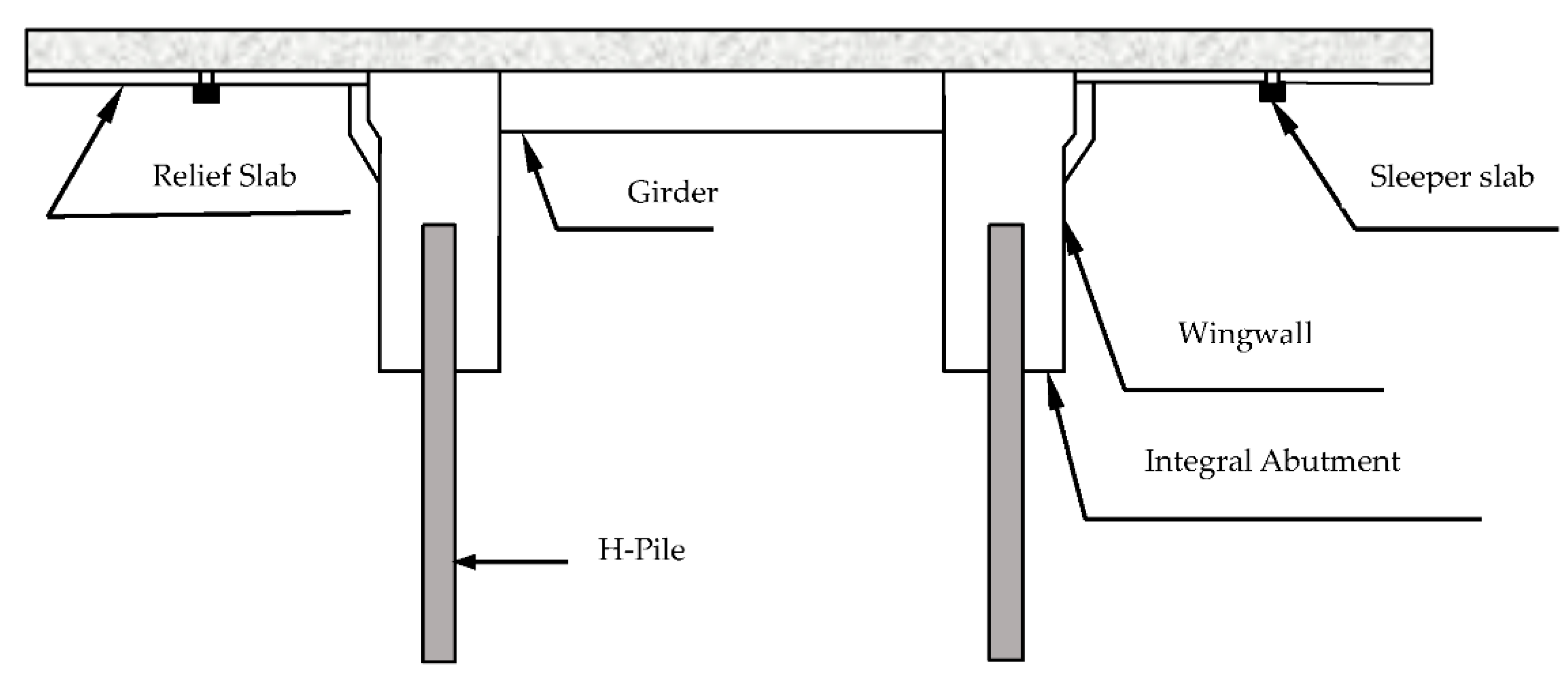
Few states provided advice on mitigation measures to lessen the effects of the SSI in integral bridges (IABs and SIABs). A thick sheet of compressible inclusions (e.g., polystyrene, expanded polystyrene (EPS) and expanded polyethylene pad) has been recommended to be used behind the integral and semi-integral abutments in some states [34,41,42]. The use of approach slab is the most common method adopted by these states to minimise the settlement and cracking issue near the bridge abutments. The integral connection between the approach slab and bridge abutment helps to shift the soil settlement away from the abutment, to where soil settlement is less problematic, and maintenance is more accessible and less expensive. In addition to the approach slab, some states (e.g., Idaho [32] and New Hampshire [43]) have recommended using a sleeper slab at the end of the approach slab to compensate for the settlement and movements at the end of the approach slab.
For ease of reading, a more detailed summary of the recommendations from several USA state DOTs regarding the types of abutments in integral bridges, limiting criteria for selecting integral bridges, and design parameters and mitigation measures, particularly in respect of geotechnical requirements, are presented in Appendix A, Appendix B, Appendix C and Appendix D.

3.2. UK Practice

In the UK, the BSI published PD 6694-1:2020 Recommendations for the design of structures subjected to traffic loading BS EN 1997-1:2004+A1:2013 [25]. BS EN, the British counterpart of European Standard (EN), is released by the BSI. Since EN 1997-1 [44] does not have specific design requirements for integral bridges, it refers to an earlier UK Highway Agency design manual BA 42/96 [45] to design integral bridges. The design recommendations in BA 42/96 [45] did not incorporate the response of backfill soil behind bridge abutments subjected to cyclic thermal movements. Moreover, information contained in BA 42/96 [45] has not always been correctly interpreted by practitioners. Meanwhile, a number of studies, for example [12,14,46,47], and [48], also found that repeated cycles of thermal movement have resulted in an increase in soil pressure. PD 6694-1 [25] updates the information in BA 42/96 taking into consideration of the effects of soil–structure interactions in alignment with the findings reported by these researchers.
The PD 6694-1 [25] recommends two methods of analysis for the design of integral abutments: limit equilibrium approach and SSI analysis. It states that the limit equilibrium approach is applicable for the design of the integral abutments satisfying the following criteria:
  • the characteristic thermal movement of the end of the deck is less than or equal to 40 mm;
  • the skew angle does not exceed 30°.
Here, the characteristic thermal movement is defined as the total thermal movement of the end of the deck from its maximum contraction position to its maximum expansion position, based on the maximum and minimum uniform bridge temperature for a 50-year return period. It further states that the affected depth of soil due to the abutment movement can be identified without SSI analysis for the following abutments:
  • abutments on spread footings (e.g., full height frame abutments as shown in Figure 1a);
  • end screen abutments;
  • abutments seated on pile caps with more than one row of piles, provided that the sway at pile cap level is sufficiently small for at-rest earth pressure to be considered at pile cap level.
However, for other types of abutments, such as integral abutments on single rows of piles and embedded wall abutments, and for over-consolidated backfill material, cohesive soil and layered soil, limit equilibrium methods are not adequate. Hence, SSI analysis should be used to calculate the horizontal earth pressure behind integral abutments.

Limit Equilibrium Approach

For abutments such as bank pad and semi-integral abutments, where the thermal movement is accommodated by abutment translation without rotation, PD 6694-1 [25] recommends the limit equilibrium method. The design earth pressure coefficient for expansion ( K d * ) may be calculated using the following equation but should not be taken as greater than ( K p ; t ) :
K d * = K 0 + ( 40 d d z ) 0.4 K p ; t
where d d = wall movement of the end screen calculated at z 2 below the ground level following clause 9.4.2 [25], z = height of the end screen, and K p ; t = passive earth pressure coefficient determined using the design value of the internal friction angle ϕ t r i a x from a triaxial test.
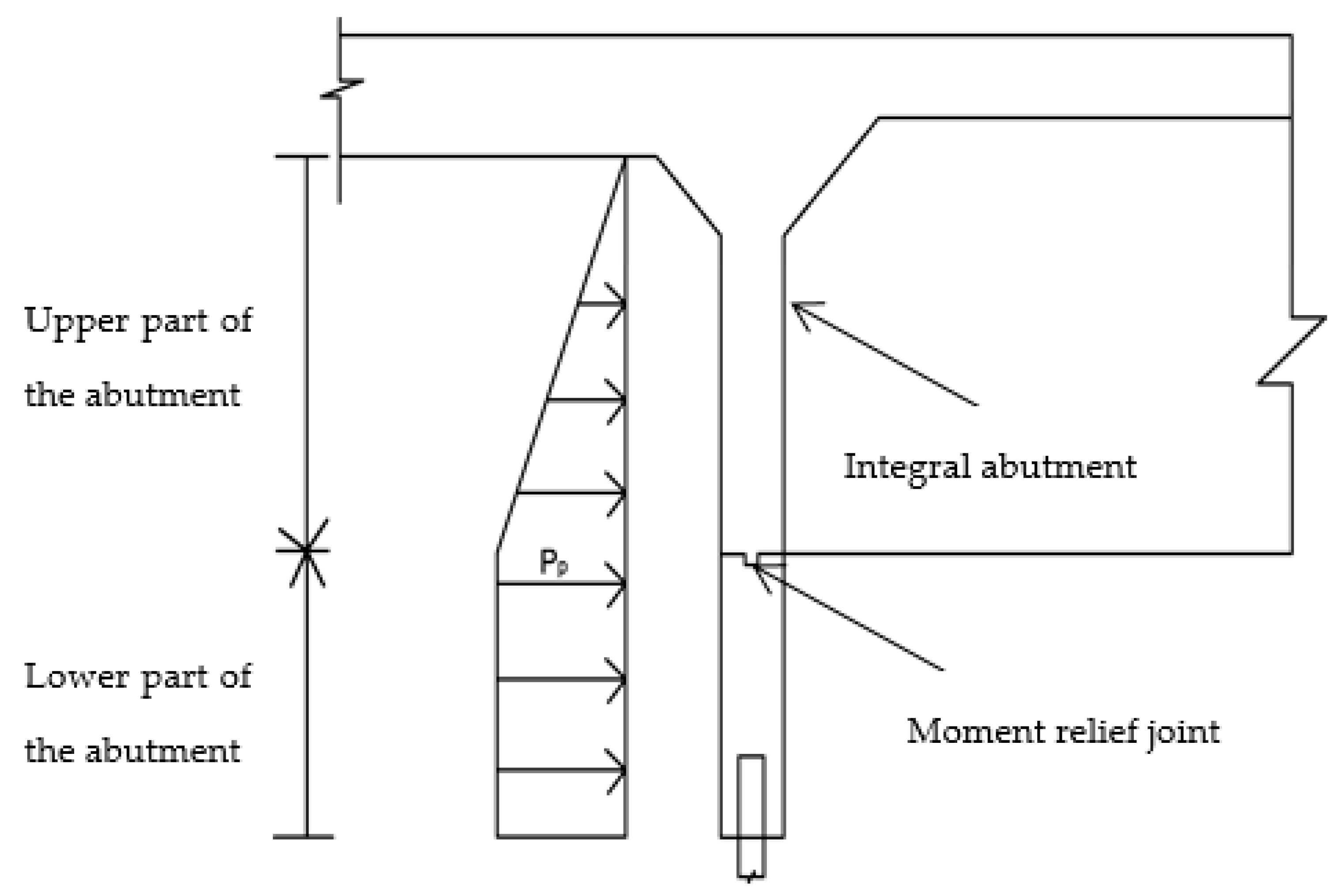
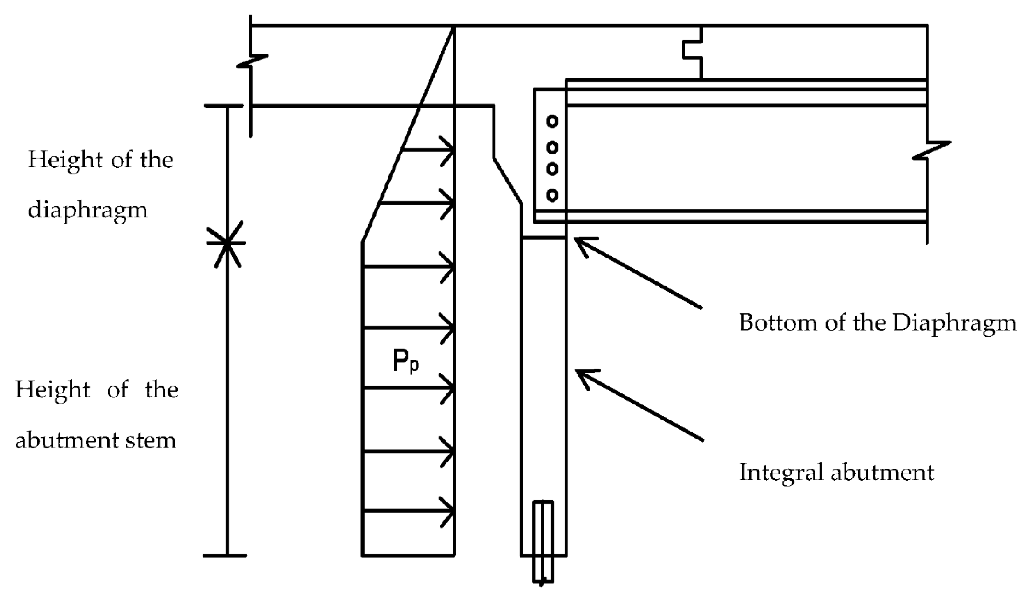
As shown in Figure 2, for these types of abutments, the pressure diagram is assumed to be (right) triangular with the design pressure at depth z equal to γ K d * z γ G , where γ G is the partial factor for the weight of soil.
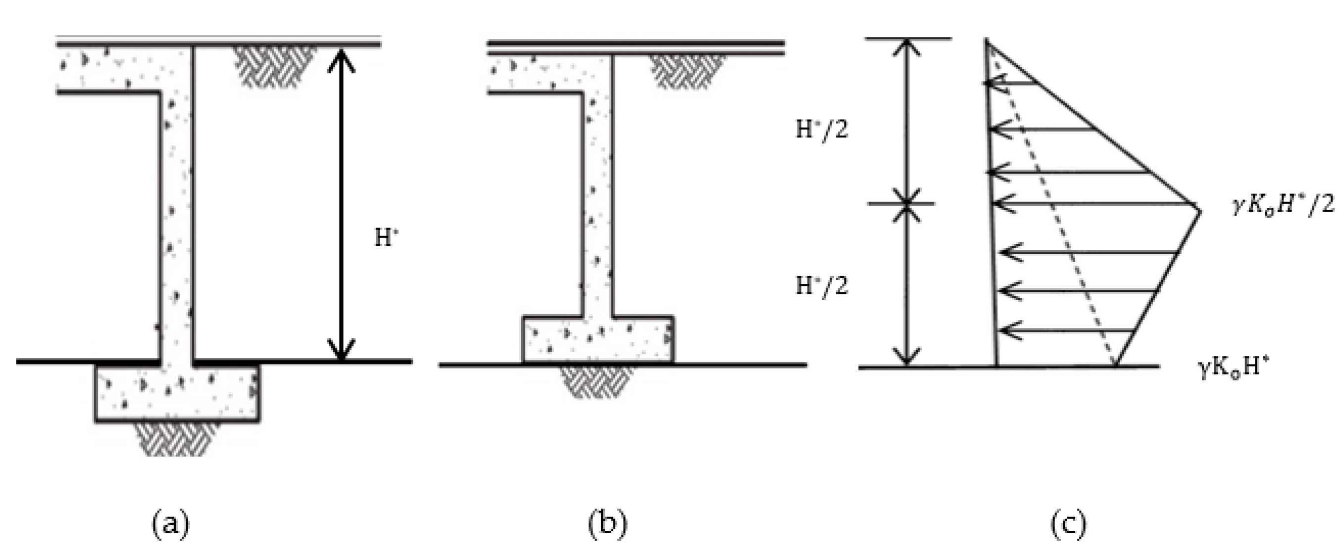
For abutments designed to accommodate thermal movements by rotation or flexure and/or combination of both, such as full height abutments on spread footings, PD 6694-1 [25] suggests a linear increase of an earth pressure coefficient corresponding to the value K d * over the top half of the retained height of the wall, but the earth pressure then decreases linearly from K d * at mid-height to k o at depth H* as shown in Figure 3. For such abutments subjected to cyclic translational movements, PD6694-1 [25], clause 9.4.3 recommends the following equation to calculate K d * , but should not be taken as greater than K P ; t :
K d * = K 0 + ( C d d H * ) 0.6 K p ; t
where H* is the vertical distance from the ground surface to the level at which the integral abutment is expected to rotate, which is the top of the base slab for rotationally rigid foundations (see Figure 3a) and the underside of the base slab for rotationally flexible foundations (see Figure 3b), and
  • C depends on Young’s modulus of the subgrade, E;
  • C is 20 for foundations on flexible soils (E ≤ 100 MPa);
  • C is 66 for foundations on rock or soils (E ≥ 1000 MPa), and C may be calculated by linear interpolation for values of E between 100 and 1000 MPa.
d d may conservatively be taken as 0.5 d d for abutment with rotationally rigid foundation (see Figure 3a), and 0.7 d d for abutments with pinned walls or rotationally flexible foundations (see Figure 3b). Furthermore, it may be determined using a realistic model of the abutment considering the effects of earth pressure applied to it.
For the limit equilibrium approach, the design value of total thermal movement ( d d ) is taken from the characteristic minimum temperature position, i.e., d d = 0.5 d K ( 1 + φ γ Q ) where d K is the characteristics value of the movement range, and γ Q and φ are partial factors for thermal actions (BS EN 1990:2002+A1, 6.3.1).

3.3. Australian and New Zealand Practices

The Australian Bridge Design Guideline, AS 5100:2017, does not contain any design information for integral bridges [49,50]. Therefore, some states have developed their own design guidelines for integral bridges in conjunction with the AS 5100:2017, such as VicRoads BTN2018/010 by Victoria, Bridge Policy Circular BPC 2007/05: Design of integral bridges [51] by NSW, and Design Criteria for Bridges and Other Structures by Queensland Department of Transport and Main Roads (TMR). State design guidelines in Australia on integral bridges regarding both structural and geotechnical (which includes lateral earth pressure) aspects are mainly based on BA 42/96 [45] and/or PD 6694-1 [52].
According to the design manual published by the Queensland Department of TMR, the increase in lateral earth pressure due to the stress ratcheting effects needs to be considered in the design of the integral bridges, and the design specifications can be based on the geotechnical investigation report, and consideration of established design guidelines, such as:
  • Design Manual for Roads and Bridges, Design of Integral bridges BA 42/96 [45];
  • PD 6694-1 [52] Recommendations for the design of structures subjected to traffic loading to BS EN 1997-1:2004. PD 6694-1:2011 is now superseded by PD 6694-1:2011+A1:2020 [25].
VicRoads BTN2018/010 is primarily based on the UK BA 42/96 [45], recommendations given by the United States Precast/Prestressed Concrete Institute (PCI), and research and case studies conducted in the UK. However, secondary sources for the design and specifications shall be obtained from the AS 5100 and other Victorian and/or Australian design standards [49,50].
Design requirements and limitations specified in the NSW Bridge Policy Circular BPC 2007/05 [51] are based primarily on the UK BA 42/96 [45], design practices in the USA, and VicRoads BTN2007/014.
Bridge design engineers in New Zealand generally refer to the Transport Agency (NZTA) Bridge Manual for guidance on the design of integral bridges, including specifications on the lateral earth pressure [53]. The geotechnical provisions for calculating the earth pressure distribution behind the abutments of integral bridges are provided in NZTA’s Bridge Manual and NZTA research report 577 [54] based on the provisions of BA 42/96 [45] and PD 6694-1 [52]. It has further emphasized the parameters that need to be considered for the SSI analysis for full height integral abutments founded on a single row of vertical piles and integral embedded wall abutments (which will be discussed in Section 3.9.1).

3.4. Canadian Practices

The construction of the integral bridges in Canada started in 1970 [55]. Most of the provinces in Canada have their own design guidelines for the design of integral bridges (for e.g., Alberta, Ontario, and Manitoba). In Alberta, both integral and semi-integral bridges are used in practice and discussed in their design guidelines [56]. Alberta limits the span of its integral bridge typically to 100 m for the IAB and 60 m for the SIAB, with skew angle less than 20°. Alberta sub-categorised the abutments for SIAB: (a) semi-integral abutment with pinned connection, (b) semi-integral abutment with sliding bearings, and (c) semi-integral abutment with partial backwall. For the semi-integral abutment with pinned connection, there is a pin connection between superstructure end and abutment, and only a single line of H-pile is recommended for such type of abutment. Where a single line of H-pile is not applicable (such as stiff soil condition and skewed bridges), a semi-integral abutment with sliding bearings with the double row H-piles or stiff piles is recommended. A distinguishing type of semi-integral abutment, the so-called “semi-integral abutment with partial backwall”, is similar to the semi-integral abutment with sliding bearings but with partial height backwall. Unlike others, in a semi-integral abutment with partial backwall, the approach slab slides over the partial backwall, which helps to reduce the earth pressure behind the end of the superstructure due to cyclical movements. Specifications regarding the geometry requirements of the components of the integral bridges (e.g., size of the abutment, length of the wingwall and depth of the girder) are advised to minimise the earth pressure on the abutment and abutment foundation. Although a comprehensive design of integral bridge with pile foundation is recommended, for example, detailed design analysis of the pile with the development of the plastic hinge, detailed information for the careful design of the abutment pile foundation has not been discussed. Furthermore, it is advised to design the abutment for the at-rest earth pressure.
Ontario has limited the total bridge span length to 100 m, and skew less than 20° for both IABs and SIABs. In addition, it has limited the height of the abutment to 7 m and length of the wingwall to 6 m to reduce the effect of soil pressure on the abutment [57]. SIABs are advised to be used only if IABs are not appropriate (e.g., total length of the pile required for foundation is less than 5 m). Piles less than 3 m in length are generally not economical, and, in that case, SIAB with spread foundation, or the use of caissons should be investigated. Integral abutments are normally designed for the active earth pressure.

3.5. Japanese Practices

Integral bridges are not as popular in Japan as in the USA and UK. The jointless bridge without bearings has been defined as either the portal frame bridge (PFB) or integral bridge based on the connection between the superstructure and substructure [58]. If there is a hinged connection at the connecting part between the super and substructure in the jointless bridge, it is defined as the integral bridge. On the other hand, if there is a rigid connection between super and substructure in the design, the bridge is known as the PFB. After 1995, because of the lack of design guidelines of the integral bridges, and its poor performance in the extreme earthquake condition, PFBs have been extensively constructed in Japan instead of integral bridges [59]. Based on the definitions gathered from the other sources and practices in many countries, which have been discussed in Section 2, PFB can be considered as an IAB, and the integral bridge as an SIAB. There are no design guidelines available for the design of integral bridges in the Design Standards of Railway Structures and Specification for Highway Bridges [60]. However, some companies in Japan, such as NEXCO, have included design guidelines for the single span integral bridges in their Design Guidelines Part II [61]. In the Design Guidelines Part II [61], the maximum skew angle allowed for the design of integral bridge is 15°, and it is advised to consider one side earth pressure for each abutment, and Coulomb earth pressure theory is recommended to be used to calculate the earth pressure. The bridge length limit and SSI analysis method are not discussed and included in the design guidelines. Guidelines for Planning of Steel Integral Bridges (draft) [62], developed by Public Works Research Centre and Nippon Steel Corporation, also proposed the design guidelines for the single and multiple span bridges. The allowable maximum bridge length is limited to 50 m, and the skew angle limit is 0°. It also advised to consider the earth pressure, but there is little detailed information provided to calculate the design earth pressure and consider the SSI effects [60].

3.6. Swedish Practices

In Sweden, all types of integral bridges are commonly called “end screen bridges”, irrespective of the connection between the super and sub-structure of the bridge structure [63]. In end screen bridges, end screen is integrally connected to the end of the deck and vertical forces are transferred to the foundations and soil through separate piers or a wall. In the most common practice, there is a bearing connection between the upper part of the vertical structural member and bridge girder. The maximum bridge length limit is 60–90 m for the concrete bridges and 40–60 m for steel–concrete composite bridges depending on the average low temperature [63]. Unlike others, the maximum bridge length limit is determined on the basis of acceptable pavement cracks in the approach embankments [63]. The earth pressure behind the abutment due to the abutment displacement is calculated using the equation as shown below [64,65]:
p = { p O if   δ = 0 p 0 + C 1 δ 200 H ( p p p o ) if   0 < δ < H 200 p 0 + C 1 ( p p p o ) if   δ > H 200
where:
  • C 1 = 1 (for unfavourable earth pressure conditions, such as forces from temperature changes)
  • C 1 = 0.5 (for favourable earth pressure, such as forces from braking vehicle)
  • p o = at-rest pressure
  • p p = passive earth pressure
  • H = abutment height
  • δ = horizontal abutment displacement towards the embankment.

3.7. Swiss Practices

In Switzerland, the construction of the integral bridges has increased significantly during the main construction period (1960–1985) of the national motorway network [66]. The design guidelines published in 1990 by the Swiss Federal Roads office (FEDRO) avoided the use of expansion joints for the bridge length between 30 m to 60 m. As a result, by now, more than 40% of the bridges in the FEDRO network are integral bridges. The revised FEDRO guidelines [67] have advised on the limit for the bridge end displacement as 30 mm for integral bridges (IABs and SIABs) rather than the maximum bridge length limit [66]. The passive earth pressure behind the abutment is usually calculated using Coulomb or Rankine theories.

3.8. Finnish Practices

In Finland, interest on the construction of the integral bridges has increased considerably in recent years. According to Kerokoski [68], by 2004, there are almost 7.2 per cent of the total bridges constructed as integral bridges. In the design guidelines, the limit criteria on the selection of the integral bridge construction are provided on the basis of the expanding length, traffic load and skew angle of the bridge. The limiting criteria are based on the expansion length, rather than the bridge total length, like criteria given by Ohio [36] and New Jersey [39] DOTs for the design of integral bridges. The maximum expanding length for the integral bridges is 35 m in the case of a normal load bridge and 45 m in the case of light traffic bridges. If the bridge is totally symmetric (0° skew), maximum expanding length for the integral bridges is 70 m in the case of normal load bridges and 90 m in the case of light traffic bridges. The design guidelines advised to design the integral abutment for the passive earth pressure based on the work conducted by Finnra (2000, cited in Kerokoski [68]). According to the design guidelines, a small amount of abutment displacement, 0.002H and 0.006H, is sufficient to produce passive earth pressure on an integral abutment for the dense sand condition and loose sand condition, respectively. SSI analysis of integral bridges is recommended, and it advised to consider the SSI effects caused by the bridge deck expansion due to a 30° Celsius rise in temperature and bridge deck contraction due to a 20° Celsius drop in temperature. However, the method to perform the SSI analysis is not discussed in the design guidelines.

3.9. Comments on Geotechnical Guidelines and Practices for the Design of Integral Bridges under Thermal Loading

It is evident that the lateral earth pressure specifications recommended by different states in the USA are not uniform. In addition, the design limitations with respect to the length and skew angle of the bridge, definition of skew angle, maximum allowable displacement, types of the abutment, abutment foundation, and bridge vary from state to state and are not uniformly adopted. Some states are still using the traditional Rankine and Coulomb active and passive earth pressure theories, although these classical theories are developed explicitly for retaining structures under monotonic loading. It is also found that some European countries such as Finland and Switzerland are also using traditional earth pressure theories to calculate the design earth pressure for the integral abutments. A few states (e.g., Ohio, Utah, Virginia, and Massachusetts) in the USA specified the lateral pressure coefficient on the abutment of integral bridges as a function of the abutment displacement, but most states ignored this. Researchers have found that the soil properties behind the abutment and abutment foundation change with thermal-induced cyclic displacements [8,12,14,46,47,48]. Therefore, lateral earth pressure relationships should include key influencing factors for a well-grounded design and assessment of integral bridges. Restrictions on abutment foundation are imposed in some states, such as in Utah where it is specified that spread footing should not be used in integral abutments, and, in Ohio, a single row of piles should not be used in semi-integral abutments [36,37]. States sometimes provide contradictory guidelines lacking in clarity as to why certain specific design practices have been adopted.
Where the earth pressure equations have been adopted in the USA, UK, and Sweden, the amplitude of the characteristic thermal movement and the details to calculate the design value of abutment displacement are dissimilar among the different practices. For example, PD 6694-1 [25] applies partial factors ( γ Q and φ ) to the thermal actions of the characteristic thermal movement in determining the design value of abutment displacement, whereas, in the USA, the design abutment displacement is taken directly as the characteristic thermal movement. Moreover, the design abutment displacement in PD 6694-1 also considers the flexibility or rigidity of the abutment foundation, whereas this is not adopted in the practices in the USA.
Some USA states (e.g., Massachusetts, Virginia and Idaho) recommend that the thermal effects and resulting SSI mechanisms should be considered in the design only if the designed integral bridges exceed the limits of the bridge length and skew angle imposed by the design manuals. PD 6694-1 [25] recommends SSI analysis only for the full height integral abutments on a single row of piles and embedded wall abutments. The general recommendation is that consideration of SSI may be necessary to take into account the actual stress ratcheting effect. However, there is little mention of soil flow, soil slumping, and settlement trough that may result in settlement bump at the abutment approach.
It is noted that the popularity of the integral bridges is significantly increasing in European countries. Out of the European countries discussed above, most of them have ignored the effects of the cyclic abutment displacement and SSI effects on the abutment and on the overall integral bridge system.

3.9.1. SSI Analysis

The impact of SSI is more significant in an integral bridge than a traditional bridge because of thermal changes which are not accommodated but are instead transmitted to the backfill and/or foundation soil [8,69,70,71,72]. Some states in the USA, such as Virginia and Massachusetts, recommend analyzing the SSI mechanism of integral bridges using 3D analysis. However, comprehensive design guidelines to estimate the actual stress ratcheting effects with the consideration of the SSI mechanism have not yet been included in guidelines published in the USA and most of the European countries (excluding the UK), Canada, and Japan.
For the embedded wall abutment and full height frame abutment founded on a single row of vertical piles, PD 6694-1 [25] does not recommend the limit equilibrium approach. PD 6694-1 advises that, for such abutment types, more comprehensive and complex full soil–structure interaction analysis is required to determine the effects of the resistance provided by the soil subjected to stress ratcheting. Furthermore, PD 6694-1 suggests that, for bank pad abutment founded on a single row of piles, the abutment may also be designed as a piled foundation using SSI analysis.
According to the NZ Transport Agency research report 577 [73], SSI analysis of full height frame abutments founded on a single row of vertical piles and embedded wall abutments should consider the same factors as reported in PD 6694-1 [25], which is discussed in Section 3.9.1.1 below.

3.9.1.1. SSI Analysis Based on PD 6694-1

PD 6694-1 [25] provides a method for determining the earth pressures behind embedded wall abutments and full height frame abutment using SSI analysis. The SSI analysis needs to be carried out using the numerical model. The method has been calibrated against a number of experimental results reported by England et al. [12], Springman et al. [14], Tapper and Lehane [47], and Hambly et al. [74]. Furthermore, it is advised that the SSI analysis method may be used as an alternative design option to the limit equilibrium method for frame abutments on spread footings. For the calculation of the lateral earth pressure profile along the integral abutment at various depths below the ground level, PD 6694-1 [25] advises that the following points should be considered for the SSI analysis:
  • the nonlinear response of the backfill to deck expansion and contraction;
  • the effect of cyclic movement of an abutment on soil properties, which may be based on 120 cycles with a magnitude of characteristic thermal movement ( d K );
  • variation of soil properties at different depths and at different strains;
  • the degree of compaction of soil;
  • the superimposed thermal effects of daily and seasonal temperature changes;
  • the rotational and axial stiffness of the deck;
  • horizontal soil arching between piles;
  • in certain conditions, minimum earth pressure can be more vulnerable than maximum earth pressure. Therefore, the pressure envelope design covering all the possible conditions of expansion and contraction is needed. This should incorporate the possible combinations of minimum earth pressures with maximum expansion and maximum earth pressures with minimum expansion.
PD 6694-1 [25] advises that an appropriate numerical model capable of addressing all the factors to be considered as described above is required for numerical modelling. It further advises that the analysis approach needs to be calibrated against comparable experience, experimental results, field monitoring data, laboratory modeling, and/or case histories. There are few studies examining the SSI effects of integral abutments with different modes and magnitude of abutment movements on abutment foundation and backfill. The small scale (1 g) tests conducted by England et al. [12] were for a stiff abutment subjected to different magnitudes of cyclic rotational movements. Springman et al. [14] investigated embedded and spread foundation abutments retaining Leighton Buzzard sand under a range of cyclic movements in the centrifuge. Tapper and Lehane [47] also studied an abutment pinned at the base, retaining sand in the centrifuge under cyclic amplitudes of 0.10%, 0.40% and 1.26% d/H.
England et al. [12] reported that a significant lateral stress increase occurred in the first ten cycles, and the rate of increase slowed afterwards and then continued towards a steady-state condition. In contrast, Springman et al. [14] found that the increase in lateral stress was insignificant under small number of cycles but significantly higher under a large number of cycles. However, the rate of lateral stress increase was much less after the first twenty cycles. With more than a thousand cycles, Tapper and Lehane [47] showed that lateral stress kept increasing until the passive pressure limit was reached. Therefore, it is evident that the test findings are not always consistent and conclusive.
For the consideration of the rotational and axial stiffness of the deck, it is advised that the SSI model may be done explicitly or by using elastic lateral and rotational springs. Furthermore, to model the soil response using the springs, it is advised to convert the elastic modulus to equivalent spring stiffness, which varies with the depth and the applied soil strain. An approximate expression developed by OBrien et al. [75] may be used to convert the elastic modulus of the soil to the horizontal spring stiffness per square meter of the backfill behind the abutment:
K h o r , d 4 π E d ( L T H e ) 0.6 H e
where:
  • K h o r , d is the designed horizontal spring stiffness per square meter;
  • E d is the design elastic modulus of the soil;
  • H e is the height of the end screen or wall; and
  • L T is the width of the abutment.
For the soil model, PD 6694-1 [25] advises that the soil needs to be modelled as an elastic medium with designed earth pressure restricted to lie in between active pressure and quasi-passive limit. Quasi-passive limit is defined as the limiting passive resistance of the soil at an applied average rotational strain in the soil used in the SSI analysis. The sub-grade reaction model and continuum model may both be used to model the soil medium. The soil model with the number of soil layers based on the depth of the soil influenced by the abutment movement with properties of the backfill material (e.g., weight density, angle of shearing resistance, and elastic modulus) are needed to be modelled in the SSI analysis. The variations in the soil stiffness with depth for a given applied soil strain should be considered with each repeated cycle, and it needs to be derived either directly from the triaxial tests of the soils or based on the available published data.
For the granular soils, the effects of the repeated thermal cyclic movements need to be considered. For the cases with the lack of in-depth analysis, it is advised that the soil stiffness can be derived by assuming densification to at least 90% based on the findings of Seed and Idriss [76], and then multiplying the soil stiffness by a factor of 1.5 based on the works of Clayton et al. [46], or any other approach that satisfies these criteria. The stress at the abutment–soil interface due to the cyclic thermal movement of bridge abutments cannot be calculated simply from the statistical equation. The development of the soil model for SSI analysis, which is governed by the complex SSI mechanism defined in terms of the cyclic thermal movements of the integral abutments, is required.

3.9.1.2. Comments on SSI Research Studies and Current Published Guidelines

According to Al-Qarawi et al. [8] and England et al. [12], when the abutment moves into the backfill behind the abutment, it causes soil densification, which increases the lateral earth pressure on the abutment. On the other hand, when the abutment moves away from the backfill, the granular soil flows towards the additional volume created adjacent to the abutment, thus reducing the soil density and lateral earth pressure. England et al. [12] reported that a balance between the opposite effects of soil densification and granular flow could be reached when both effects are of comparable magnitude, leading to steady-state cyclic lateral earth pressures. At this moment, residual volumetric strain changes become insignificant with increasing cycles [8], resulting in closed hysteresis loops, which means that the shakedown state has been reached [8,20,77,78]. The abutment type, mode, and range of movements significantly impact the lateral earth pressure development. Most importantly, the design recommendations based on the full-scale tests are still lacking. More monitoring of various types of abutments, with different abutment foundations, and in all possible cases and conditions of abutment movement are thus needed to further clarify and justify the current design approaches.
Clayton et al. [46] performed strain-controlled stress path triaxial tests on clay samples, pluviated granular samples (Leighton Buzzard sand) and glass ballotini. Samples were tested at different stress paths and cyclic straining experienced by backfill soil located at mid-height behind integral abutments (full height frame abutment and embedded wall abutment). The loading scheme for the laboratory triaxial tests was based on five factors: (a) the location of the representative soil element and size of the idealised integral abutment, (b) the initial stress on the soil element, (c) the total stress path that would be imposed on the representative soil sample because of abutment movements, (d) the amplitude of the strain cycles that would be imposed as a result of temperature change and deck length, and (e) the initial loading direction. Results showed that there is no accumulation of lateral earth pressure in the clay samples and glass ballotini. However, there was a significant increase in lateral earth pressure for almost all cyclic strain levels in the pluviated sand specimens. It should be noted that the total stress path considered was constant, irrespective of the imposed strain cycles and magnitude of strain cycles based on the typical range of temperature cycles and bridge deck length. The results from Clayton et al. [46] help develop the guidelines in PD 6694-1 [25]. While their observations and findings are valuable, the cyclic stress paths emanating from soil–structure interactions in an actual integral abutment are more complex; it may not be possible for a triaxial test to capture the SSI comprehensively.
Integral bridges founded on piles are the most common practice in the USA, Europe, Australia and other Asian countries. Razmi and McCabe [20] used three different methods to compute the thermal displacement of piles and abutment: (a) the AASHTHO [23] which computes the movement as the free expansion = α L T , where α is the coefficient of thermal expansion, L is the expansion length, and T is the difference between the extreme temperature and installation temperature, (b) an analytical method, using classical mechanics theory, which only considers the increase in soil pressure on the piles due to thermal movements, and (c) a 3D finite element modelling (FEM), which considers both effects from mechanical loads and the soil pressure due to temperature variations. The comparative results indicate that the piles and abutment displacement using the AASHTO [23] method is higher than the other two methods. Since the analytical method only considers the soil pressure on the piles and excluded the soil pressure on the abutments, the calculated displacement from the analytical method is also significantly higher than that from the FEM method. Consequently, the effect on the abutment–soil interaction due to the presence of pile foundations and the combined effect of the abutment on the pile–soil interaction requires more investigation.
The stress profile during the cyclic movement of the abutment from the neutral position could be different to when the cyclic movements start from a different position of the abutment wall. In addition, it was observed by Clayton et al. [46] that the increase in lateral stresses occurred only if the active state was reached at the end of each cycle. They postulated that the readjustment of the soil fabric due to rotations of non-spherical sand grains at the active state contributed to the build-up of maximum horizontal stress. However, it is not associated with the densification during cyclic movement, which was confirmed by subjecting spherical glass ballotini to the same stress path when no build-up of horizontal stress occurred. Hence, further tests at various magnitudes of cyclic abutment movement and at the different direction of the initial loading are needed to confirm the current design approaches and postulate further recommendations for future design methods depending on the starting point of cyclic loading movement.
Sandberg et al. [7] performed a comprehensive SSI study on a 140 m long integral bridge and compared the obtained earth pressure distribution behind the abutment with the earth resistance calculated using the Limit Equilibrium (LE) approach specified in PD 6694-1 [25]. For the SSI approach, a soil model that satisfied clause 9.2.2 in PD 6694-1 was developed, and soil stiffness parameters for the SSI analysis were taken from the published literature. The stress profiles obtained from the LE approach and SSI approach were found to be significantly different. It was reported that the SSI stress profile at the top of the abutment follows the passive limit ( K p ; t ) . In addition, the stress profile below the peak resistance from the SSI approach was significantly less than that of the LE approach. This being the case, the authors recommended further studies on the range of abutment types and stiffness to correlate the effects of stiffness of the structure and soil on the performance of integral bridges.
An experimental study conducted by Huang et al. [17] to examine the combined effects of abutment–soil interaction and pile–soil interaction under cyclic horizontal displacements has also confirmed the stress ratcheting effects behind the abutment. From the experimental results, it was found that the earth pressure coefficient was approximately equal to the passive earth pressure coefficient suggested by the England et al. [12], NCHRP [79], Burke and Martin [80], Chen [81], Helmut [82] and Dicleli [83] when H is lower than 0.004. Moreover, the earth pressure coefficient was approximately equal to two-thirds of the earth pressure coefficient of Rankine theory but significantly less than that from Coulomb theory. When H is higher than 0.004 and less than or equal to 0.006, the passive earth pressure coefficient Kp from England et al. [12], NCHRP [79], Burke and Martin [80], Chen [81] and Dicleli [83] are less than that of experimental results. Moreover, K P from Rankine theory is close to the test result, but still far less than the Coulomb theory when H reaches 0.006. The testing earth pressure coefficient is larger than all of those except Coulomb theory when H is between 0.006 and 0.012. However, it exceeds the Coulomb theory when H is larger than 0.012. The coefficient K P from this test was 3.33 times as much as that of Rankine theory and 1.27 times as much as that of Coulomb theory when H is equal to 0.016. The authors also reported that the shape of the pressure distribution depended on the magnitude of horizontal displacement, namely it was triangular in shape when the abutment displacement is less than 8 mm, and trapezoidal for the displacement larger than 8 mm. Void formation behind the abutment and at the interface between abutment and pile was also observed in the experiment, whereas the pressure distribution given by PD 6694-1 [25] for different types of abutments depend on the mode of abutment displacement and the type of abutment. The test results suggest that more research to correctly estimate the passive pressure and pressure distribution on the abutments and abutment foundation is needed.
Many prior studies have ignored the combined effect of the abutment–soil interaction and pile–soil interaction during the thermal displacements of the bridge superstructures. Most of the integral bridge design practices have also ignored the earth loads on the abutment due to the thermal movements in the design of the pile foundation [6].
It is evident that the SSI analysis approach suggested by PD 6694-1 [25], bridge design manuals published by DOTs of USA, Canada, Japan, Sweden, Spain, Switzerland, Finland, Australia and New Zealand on integral bridge design still lack sufficient details in one way or another. Not a lot of attempts have been made in the design guidelines to address the “bump at abutment approach” issue. Design guidelines on how to incorporate all factors affecting the SSI mechanism should be carefully studied. Research to understand the complex SSI behind the integral abutment and abutment foundation is required to correctly estimate the stress ratcheting effects [8,12], slumping, wedging and densification of the soil behind the abutment, and to address persistent settlement issues at the abutment approach.

3.9.2. Proposed Strategies to Minimise the Effects of SSI

The adverse effects of SSI may be mitigated using the principle of isolation [4,84,85,86]. Three degrees of isolation are generally used between the bridge structure and the backfill/foundation soil to deal with soil–structure interactions, namely:
  • No isolation;
  • Partial isolation;
  • Full isolation.
The interactions may include superstructure and/or substructure interactions with backfill/foundation soils or both. The soil–structure interactions are complex and depend on (a) traffic and environmental loadings; and (b) the design of the integral and semi-integral abutment, abutment foundation and backfill/foundation soils. While the vicissitudes of traffic and environmental loadings are difficult, if not impossible, to control, engineers have some control over the design of the integral bridge. The question is in choosing the appropriate ways to mitigate or manage the adverse effects of soil–structure interactions in integral bridges with or without soil–structure isolation. This can only be answered by rigorous investigation and developing critical insights and understanding of the soil–structure interactions.
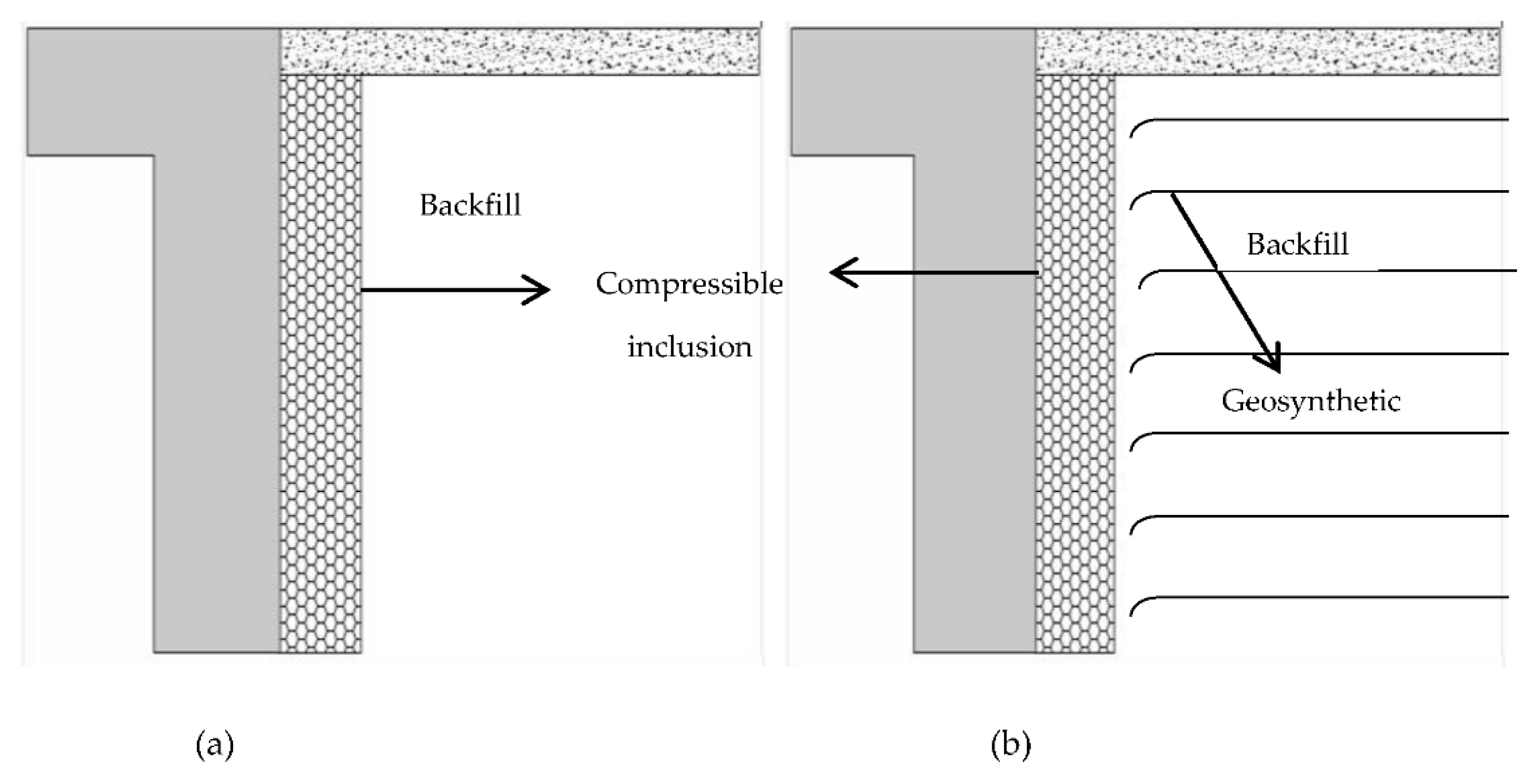
Partial and full isolation techniques such as (a) placing compressible inclusions (CIs), made of low stiffness, highly compressible, and elastic materials, between the abutment and the backfill [15,34,41,42] (Figure 4a,b) MSE stabilised embankment with compressible inclusion [10,15,86] (Figure 4b) have been proposed to minimize or eliminate inherent geotechnical problems in integral bridges.
Horvath [15] suggested that a compressible inclusion (Figure 4a) would accommodate deck expansion. It helps to decrease the lateral pressure on the abutments. However, compressible inclusions seem ineffective at controlling subsidence behind the integral abutment [8,87]. In winter, as the superstructure contracts and pulls the abutment away from the backfill, compressible inclusion is unable to restrain the soil from slumping downward and towards the abutment [8,88,89].
A complete separation between the abutment and self-stable retained soil could be another solution to avoid the effects of SSI in integral abutments (e.g., using self-stable MSE approach embankment) (Figure 4b). The space between the abutment and self-stable soil can be left as a void or filled with a compressible inclusion. However, leaving a void is considered unacceptable due to the difficulty of maintenance [22].
Alberta province has avoided the use of foam inclusion materials behind the integral abutments to minimize the earth pressure behind the abutment [56]. This is because the foam material can be compressed due to backfill compaction during the construction and due to the cyclic movements, and this could lead to unequal movements at the bridge abutments. A similar recommendation is also advised by the Manitoba province, Canada. The practice in Canada contrast with most of the design recommendations to use inclusion materials behind the abutment to minimize the earth pressure due to the abutment movements.
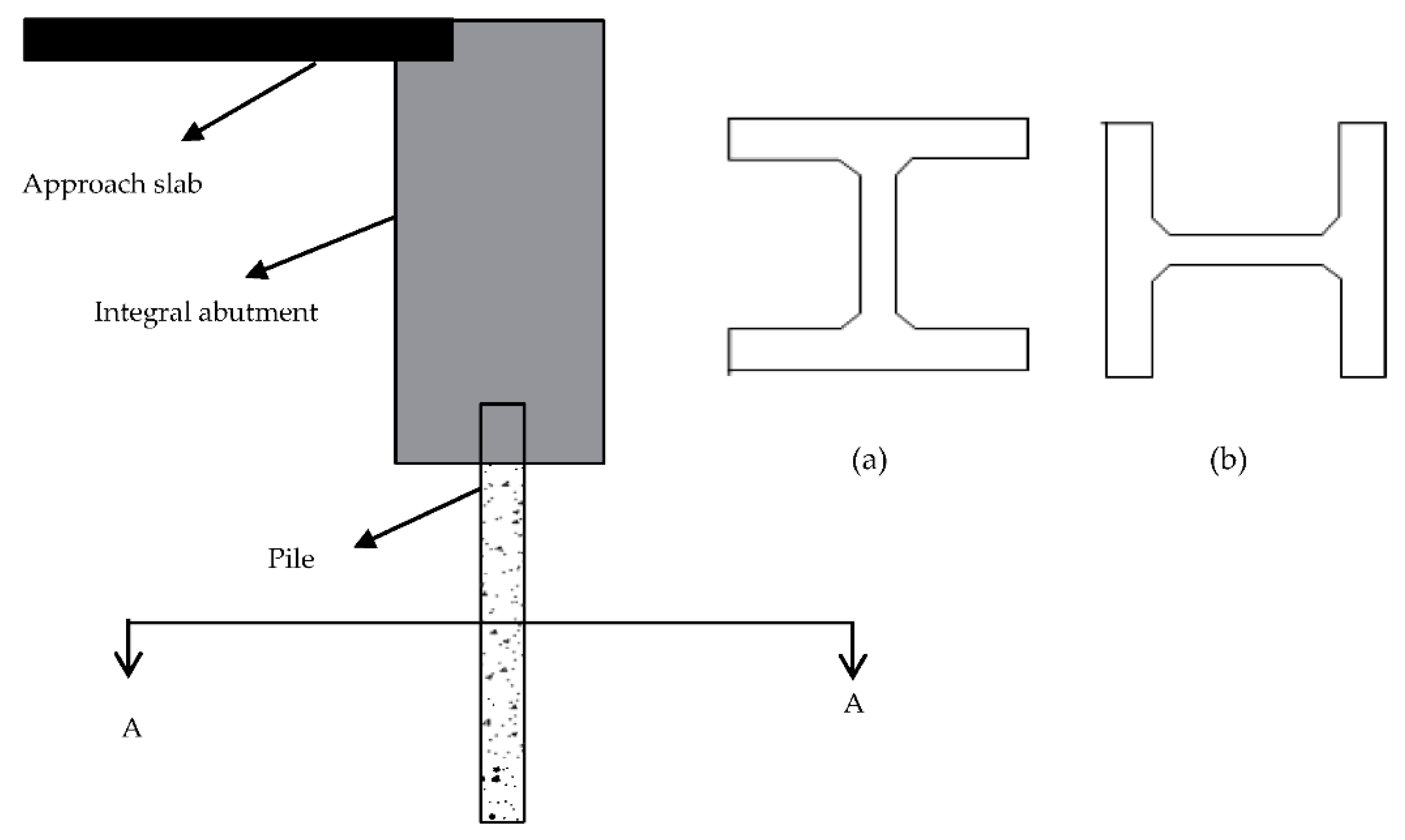
There is little or no information regarding the solutions to minimise the pile–soil interaction in the IABs. Some design practices have recommended the single row of piles and weak axis orientation with the centerline of the integral and semi-integral abutment. A study conducted by Tabatabai et al. [6] showed that 21 out of 37 states in the USA prefer to orient the pile to bend along the weak axis (due to longitudinal thermal movement), whereas 5 out of 37 prefer to orient the pile to bend along the strong axis, and five states do not have any preference. Pile orientation (see Figure 5) in integral bridges can affect the amount of restraint to the thermal movements, force in the pile and overall pile performance in the integral bridges.
In addition, pre-bored holes for piles, piles in sleeves, or corrugated pipe over the pile (see Figure 6) are recommended to avoid the pile–soil interaction, reduce the friction on the piles, and to mitigate the down drag forces. When the pile supporting the abutment is first driven into the soil, negative stress can build on the pile face. The process is called down drag, which can cause settlement issues on the backfill soil.
Finally, despite a preference for IABs over SIABs due to issues with the bearings, the benefit of installing bearings is that it provides superstructure-to-substructure isolation. This helps to mitigate the effects of superstructure expansion and contraction from transferring to the substructure and eventually interacting with the surrounding soil.

4. Conclusions

This review paper discussed the geotechnical design guidelines and practices for integral bridges in the USA, Australia, New Zealand, Canada, Japan, UK, and a number of European countries. The SSI effects on integral bridges and how they have been incorporated in the design are reviewed. Although the popularity of integral bridges is increasing, the knowledge gaps on the SSI effects and current design guidelines of integral bridges present many challenges for geotechnical engineers in mitigating stress ratcheting, settlement, and pile flexural stiffness and fatigue issues. Therefore, augmenting design guidelines to enhance the applicability of integral bridges and to mitigate the geotechnical problems will help to strengthen the current design practice. The main conclusions drawn from the past studies and current design practices of integral bridges are summarized below:
  • The nomenclatures on integral bridges in the design guidelines are not standardised across different jurisdictions. For example, AASHTO [5] defines an integral bridge as an IAB and does not further sub classify the integral bridges. In European countries, integral bridges are commonly defined as either fully integral bridges or semi-integral bridges based on the structural connection between the bridge deck and abutment, though these are analogous to the definitions of IABs and SIABs, respectively. A portal frame bridge (PFB) in Japan and end screen bridge in Sweden are other prominent examples of disparate terminologies of the integral bridges in different countries. There are also disagreements on the definitions and types of abutments in different states of the USA. In this review, we have attempted to unify some of the nomenclatures. An integral bridge is defined in this paper as a bridge structure where the bridge deck is without any joints for expansion or contraction of the deck and may be further sub-categorised as an integral abutment bridge (IAB) or a semi-integral abutment bridge (SIAB) depending on the connection between deck and abutment.
  • The design method and the design lateral earth pressure distribution behind the abutment (whether SSI is needed or not) are defined with respect to the type of abutments, length, and skew angle limit of integral bridges. In addition, the design practices of integral bridges, including threshold limits on the bridge length and skew angle, and types of abutments, vary across the literature. Knowledge gaps still exist in understanding the effects of different type and geometry of abutment, length and skewness of bridge, type of backfill and SSI. Filling the knowledge gaps is necessary to extend the application and improve the performance of integral bridges.
  • The factors considered and the equations used to calculate the earth pressure distribution behind the integral and semi-integral abutment (see Table A1 in Appendix A) in the USA vary from state to state. Some states are still using the traditional Rankine and Coulomb active and passive earth pressure theories derived for retaining structures under monotonic loading cases. In addition, the designed abutment displacement is considered as the displacement at the top, irrespective of the mode of displacement and flexibility of the abutment. Moreover, the displacement of the abutment is cyclic in nature, and the abutment displacement also depends on the nonlinear response of the backfill.
  • Most of the design practices lack comprehensive design guidelines on pile foundation for the integral bridges. The types of abutment foundation, restriction on the abutment foundation, and design of the abutment foundation (such as the orientation of the pile, type of pile and embedded length of the pile) have resulted in conflicting practices in some cases. In addition, the transferred effects from the abutment and abutment–soil interaction could have different effects on the pile foundation. Abutment–soil interactions and pile–soil interactions should be investigated in a holistic manner in the design of integral bridges.
  • Measures to reduce adverse SSI effects and the consideration of the SSI in the design of integral bridges are required. Both have been recommended in principle and to a different extent in the design standards. Some standards have advised 3D analysis of the integral bridge system incorporating the SSI (e.g., PD 6694-1 [25] and Massachusetts LRFD Bridge Manual-Part I [40]). However, there is very little information on the 3D coupled analysis of the integral bridge structure and soil. Appropriate guidelines to identify the governing soil parameters and changes in soil behavior during cyclic abutment displacement are needed to develop the numerical soil model to study the SSI mechanism in integral bridges. The numerical studies should be combined with scaled model laboratory experiments and field monitoring of actual integral bridges to gain critical insights into the SSI effects (e.g., as recommended in PD 6694-1 [25]).
  • Seasonal and diurnal temperature cycles cause dissimilar period and amplitude variations in the displacements of the bridge structure. In addition, the superimposed thermal effect (daily and seasonal temperature changes) can have different effects on integral bridges compared to the daily or seasonal thermal changes only. However, design guidelines (such as PD 6694-1 [25] and AASHTO [5]) mainly focus on the effects of the seasonal cycles. In addition, some studies found that the shape of the earth pressure distribution behind the integral abutments depends on the magnitude of the abutment displacement [17]. Some standards (e.g., PD 6694-1 [25]; Massachusetts LRFD Bridge Manual-Part I [40]; Utah Bridge Design Manual [37]) further recommend that the magnitude of lateral pressure should be considered as a function of abutment displacement. These indicate the importance of considering the superimposed effects of seasonal and diurnal temperature cycles in postulating the earth pressure and establishing the bending moment distribution on the integral and semi-integral abutment, abutment foundation, and development of the settlement trough at the bridge approach.
  • The review suggests that the principle of isolation being applied to mitigate SSI effects needs more detailed study. Abutment–backfill separation with the use of compressible inclusion and reinforced backfill (MSE wall) are just two more common approaches to mitigate the soil flow, soil slumping, soil settlement and stress ratcheting effects on integral bridges. Other self-stable backfill systems, e.g., soil-cement column wall [10] and EPS geofoam embankment [15], are potential solutions as well. However, most of these suggestions are derived from the lab experiments and finite element analysis, and no explicit design guidelines for such approaches are yet available. In contrast, Alberta and Manitoba strictly avoided the use of foam material behind the integral abutment, as they can be compressed in the long term, which could develop unequal movements at the bridge abutments. Therefore, most appropriate solutions to minimise the earth pressure behind the abutment need to be explored and discussed in the design guidelines to increase the applicability of the integral bridges, and to substitute the integral bridges as an option for longer traditional bridges.

Author Contributions

Conceptualization, L.D.S., A.A.-Q., C.J.L., S.L. and P.H.; reading, L.D.S. and A.A.-Q.; writing—original draft preparation, L.D.S.; writing—review and editing, L.D.S., A.A.-Q., C.J.L., S.L. and P.H.; supervision, C.J.L., S.L. and P.H. All authors have read and agreed to the published version of the manuscript.

Funding

This research received no external funding.

Institutional Review Board Statement

Not applicable.

Informed Consent Statement

Not applicable.

Data Availability Statement

All data are provided in the content.

Conflicts of Interest

The authors declare no conflict of interest.

Appendix A

Table A1. Integral bridge practices in USA states.
StatesTypes of Integral AbutmentsLimiting Design CriteriaGeotechnical Design Considerations/PracticesMitigation Measures with Respect to Geotechnical Requirements
Colorado [41]Integral abutments and semi-integral abutments
-
Bridge length up to 120 m for steel, cast-in-place concrete bridge and precast and post-tensioned concrete bridge.
-
Skew angle limit is 30°
-
No explicit guidelines. However, it stipulates, “Appropriate earth pressures and predicted settlement should be provided in a geotechnical investigation”.
-
A combination of mechanically reinforced earth (MSE) with a non-collapsible gap with low-density polystyrene can be considered when reduced earth pressure effects are required.
Alaska [31]Semi-integral abutments
-
Not defined
-
Thermal movement and live load effects are neglected for the abutment and abutment foundation.
-
The design of the end diaphragm of the abutments must account for the lateral earth pressure. However, the magnitude and distribution of earth pressure are not explicitly discussed.
-
Recommends using a 13 mm expanded polyethylene pad on both faces of the bearing pad to accommodate thermal movement. The bearing pad provides rotational isolation between the bridge girder and abutment.
Ohio [36]Integral abutments and semi-integral abutments
-
Bridge expansion lengths up to 76.2 m (121.92 m total length)
-
Skew angle limit is 30°
-
Integral abutment designs placed on MSE wall are prohibited, but semi-integral abutment designs are allowed.
-
No skew limitation for the semi-integral bridges.
-
Semi-integral bridges restricted when a single row of piles is used.
-
Assumes two-thirds ( 2 / 3 ) of total design movement could occur in one direction.
-
Earth pressure distribution ranging between the at-rest and the full passive pressure, which is calculated using the Coulomb equation and depends on the magnitude of thermal displacement of the abutment.
-
The movement required to mobilize full passive pressure is five percent of the height on which the passive pressure acts. Height is measured from the bottom of the foundation to the roadway surface.
-
Not defined
Idaho [32]Integral abutments
-
Bridge lengths up to 98 m for concrete bridges and 37m for steel bridges.
-
Skew effects have to be considered for a skew angle greater than 25° in which forces tending to rotate the structure shall be accounted for in the design.
-
Passive earth pressure increases linearly for the top third of the abutment, then linearly decrease to the at-rest pressure at the bottom end of the abutment (see Figure A1).
-
An in-depth analysis of soil pressure distribution is required for bridges exceeding the design criteria.
-
Vertical loads piles shall be designed in accordance with AASHTO LRFD Bridge Design Specification [90].
-
Lateral loads on piles on bridges skewed more than 25° need to be considered to resist soil pressure forces tending to rotate the structure.
-
Piles must be ductile enough to accommodate both thermal movements and dead load and live load rotations of the superstructure.
-
Approach slab is strongly recommended for integral abutment bridges with a total thermal movement higher than 19 mm.
-
A sleeper slab at the end of the approach slab with the joint seal material is required to compensate for the settlement of the approach slab and movement at the end of the approach slab (see Figure A4).
Maine [35]Full integral abutments and semi-integral abutments
-
(a) For full integral abutment;
-
for abutments with piles, bridge lengths up to 91.5 m for steel and 152.4 m for the concrete bridge structure
-
skew angle of 20° or less
-
(b) There is no limit criteria for the semi-integral abutments.
-
Coulomb triangular passive earth pressure distribution is considered in the design of fully integral abutments.
-
Rankine active earth pressure is recommended to design semi-integral abutments.
-
Bridge abutments with displacements over 25.4 mm may require a detailed pile analysis to consider all applicable forces and moment demands, including thermal, skew effects and deflections of the bridge superstructure.
-
Approach slabs should be used when integral bridge lengths exceed 24.4 m for steel structures and 43 m for concrete structures.
Massachusetts [40]Integral and semi-integral abutments
-
Bridge lengths up to 43 m for steel bridges and 61 m for concrete bridges
-
Skew angle limited to 30°
-
The magnitude of lateral earth pressure is considered as being developed to be between full passive and at-rest earth pressure, which depend on the relative wall displacement, δ T / H where H is the combined height of the pile cap and the abutment diaphragm and δ T is the horizontal displacement of the pile head.
-
Active earth pressure coefficients (Ka) shall be estimated using Coulomb theory. Passive earth pressure coefficients (Kp) shall be estimated using Rankine or Log Spiral Theory.
-
The lateral earth pressure coefficient (K) from the compacted gravel borrow backfill shall be estimated using the equation:
-
K = 0.43 + 5.7 ( 1 e 190 ( δ T H ) )
-
Bridges exceeding the specified bridge length limit and skew angle need to be analysed using the 3D Space Frame Analysis Method to determine the soil–structure interaction effects.
-
An approach slab is preferred to be used with all IABs.
North Dakota [33]Integral abutments
-
Bridge length up to 105 m and skew angle limit of 30°
-
It specifies that a uniform pressure of 47.8 kPa should be considered in the design of integral abutments and 31.1 kPa in the design of the wing walls.
-
Not defined
Pennsylvania [42]Integral and semi-integral abutment
-
Bridge total length up to 180 m for concrete structures and 119 m for steel structures
-
Minimum allowable skew* angle is 70° for a single span in excess of 40 m or for multiple span structures
-
Minimum allowable skew* angle is 60° for a single span in excess of 28 m but not longer than 40 m
-
Minimum allowable skew* angle is 45° for single spans 28 m or less
-
Note: skew* is the complement of the skew angle defined in Appendix D.
-
Only for the bridges exceeding the bridge length limit, the integral abutment bridges need to consider the effects of secondary loads such as creep, shrinkage, thermal gradient and differential settlements for the design of the integral abutment.
-
The design of abutment components is based on the full passive earth pressure.
-
Approach slabs are strongly recommended, and special backfill materials such as open-graded stone are required to be used.
-
A 51 mm thick sheet of cellular polystyrene is required against the entire area of the back face of the abutment to attenuate the earth pressure. Cellular polystyrene is a synthetic aromatic hydrocarbon polymer made from the monomer styrene, and styrene is available as a solid form or as foam having a closed-cell structure
New Hampshire [43]Integral abutments and Semi-integral abutments
-
(a) For integral abutments;
-
total bridge length up to 91 m for steel bridges and 183 m for concrete bridges
-
maximum abutment height of 4 m
-
Individual span length between supports less than 45.7 m
-
Skew angle less than or equal to 20°
-
(b) Semi-integral abutments are the preferred type of abutment when the site conditions prevent the construction of full integral abutments.
-
Design earth pressure varies linearly from at-rest earth pressure to the full passive pressure (see Figure A3).
-
The approximate values of relative movements required to reach full passive pressure could be found from AASHTO LRFD Table C3.11.1-1 [90].
-
Sleeper slab shall be used with all approach slabs.
Oregon [39]Integral abutments and semi-integral abutments
-
For service limit states, movement at the top of integral abutment piles does not exceed ±38 mm from the undeflected position.
-
Skew angle limited to 30°
-
Integral abutments with MSE walls are prohibited.
-
Semi-integral abutments preferred over integral abutments when the foundations are stiff in the longitudinal direction.
-
It does not involve any explicit description of the lateral earth pressure behind the integral abutments.
-
It states that the non-yielding walls, such as the integral abutments, must be designed using the at-rest earth pressure.
-
Not defined
Virginia [34]Full integral abutment and semi-integral abutment
-
(a) For full integral abutments;
-
- for steel bridges, length up to 90 m for 0° skew angle and 45 m for 30° skew angle
-
for concrete bridges, length up to 150 m for 0° skew angle and 75 m for 30° skew angle
-
Allowable maximum total movement at abutment is 40 mm
-
(b) For semi-integral abutments;
-
- for steel bridges, length up to 135 m
-
for concrete bridges, length up to 230 m
-
Skew angle limited to 30° angle
-
Allowable maximum total movement at abutment is 55 mm
-
Right triangular passive earth pressure distribution over the full height of the abutment is used to design the abutment against thermal movement.
-
The Kp of 4 shall be used with the designed EPS (expanded polystyrene) layer, whereas Kp of 12 shall be used for the structural backfill without EPS layer.
-
For the abutments designed with the bridge exceeding the given length and skew criteria, a 3D analysis is required to calculate the thermal effects on the bridge structures.
-
Approach slab is recommended, and joint between the approach slab and sleeper beam (sleeper slab) should be designed for the thermal movements.
-
A layer of Expanded Polystyrene (EPS) shall be provided in between the backfill and the abutment.
-
Minimum thickness of the EPS layer should be 25 cm.
Utah [37]Integral abutments and semi-integral abutments
-
Displacement of integral abutment due to temperature load should not exceed 76 mm.
-
Integral abutment is restricted to use with spread footings.
-
Displacement of semi-integral abutment due to temperature movements should not exceed 0.03 h, where h is the height of the semi-integral abutment diaphragm.
-
Semi-integral abutment is preferred when superstructure movements exceed the pile movement capacity.
-
Semi-integral abutment is preferred where differential settlement along the abutment is anticipated.
-
Design earth pressure varies uniformly over the height of the abutment, and the pressure is calculated using the formula:
-
P u = γ ( 0.03   H d ) ( 2 H d 3 )
-
where P u is the earth pressure in Ksf, γ is a load factor, in this case, it is equal to 2, ∆ is the effective abutment displacement in feet, and it is defined as the total abutment displacement gap (if any gap is provided behind the abutment) and H d is the height from the finished grade to the bottom of the abutment in feet.
-
Geofoam backfill is used to reduce or eliminate fill settlement behind the abutment.
-
If the slope of the geofoam surface behind the abutment exceeds 1. 5H:1V, the effects of soil loads transferred through the geofoam need to be evaluated. There are no explicit design guidelines for the geofoam backfill design.
Illinios [91]Integral abutments and semi-integral abutments
-
(a) For integral abutment;
-
(i) total allowable length for steel structures is 94.5 m
-
(ii) total allowable length for concrete structures is 125 m
-
(iii) maximum skew angle is 30°
-
(b) When integral abutment limitations are exceeding, semi-integral abutment should be used.
-
For design, K 0 (earth pressure at rest) = 0.5 should be used.
-
Not defined
Minnesota [92]Integral and semi-integral abutments
-
(a) For integral abutment;
-
bridge length ≤ 300 feet (91.5 m) and skew angle ≤ 20 °
-
bridge length ≤ 100 feet (30.5 m) and skew angle ≤ 45 °
-
bridge length is between 100 feet and 300 feet, and skew angle ≤ [45 − 0.125 (L − 100)], where L is the length of the bridge in feet
-
(b) Semi-integral abutments are the preferred type of abutment when the requirements for integral abutments cannot be met. For semi-integral abutments with wing walls parallel to the roadway, the maximum skew angle limit is 30°.
-
Lateral earth pressure profile varies linearly from zero to the Rankine passive earth pressure over the upper part of the abutment (above the moment relief joint) and remains constant over the lower part of the abutment (see Figure A2).
-
Not defined
Nevada [93]Integral abutments;
(a) diaphragm-with-footing-abutment, which is semi-integral abutments as described in other practices.
(b) diaphragm-with-pile-abutment, which is integral abutments (full integral abutments) as described in other practices.
-
(a) For diaphragm-with-footing-abutment;
-
bridge lengths up to 122 m for concrete and 76 m for the steel bridge structure
-
skew angle of 30° or less
-
(b) For diaphragm-with-pile-abutment;
-
bridge lengths up to 76 m for concrete and 46 m for steel bridge structure
-
skew angle of 20° or less
-
(The values are for cold climate as per 4th edition of AASHTO LRFD article 3.12.2.1 [94]. The values may be increased by 20% in areas of moderate climate)
-
AASHTO LFRD 3.11 guideline is followed to estimate the lateral earth pressure acting on the abutment of IABs [94].
-
Not defined
New Jersey [39]Integral abutments and semi-integral abutments
-
(a) For integral abutment bridge;
-
bridge length up to 137 m and skew angle limited to 30°
-
(b) For semi-integral abutment bridge;
-
maximum skew angle is 30°
-
maximum expansion length is 61 m
-
Semi-integral bridges restricted when a single row of piles is used.
-
Integral abutments need to be designed by considering the full passive earth pressure. However, the method of calculation and the distribution of the pressure are not explicitly discussed.
-
For bridge length over 46 m, provisions shall be made for expansion at the end of each relief slab by the installation of a sleeper slab. Sleeper Slab is a reinforced concrete block supporting the end of the approach slab at the approach roadway end.
(Note: all imperial units in design manuals are converted to SI units in the table).

Appendix B. Earth Pressure Distribution on Integral and Semi-Integral Abutment

Appendix B.1. Idaho
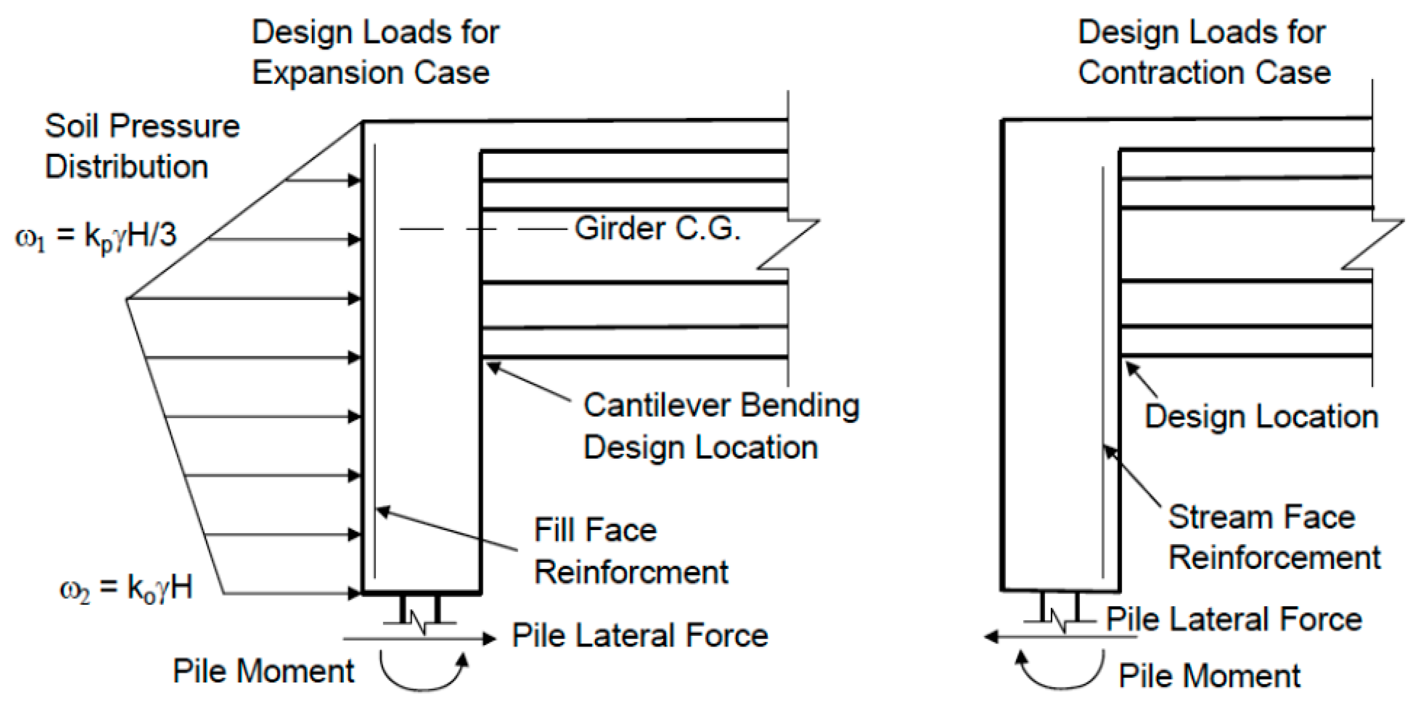
Figure A1 shows designed earth pressure distribution behind an integral abutment during bridge expansion and contraction recommended by the Idaho DOTs [32].
Figure A1. Earth pressure on integral abutment during bridge expansion and contraction—Idaho DOTs [32].
Applsci 11 07131 g0a1

Appendix B.2. Minnesota

Figure A2 shows adopted design earth pressure distribution behind and integral abutment recommended by the Minnesota DOTs [92].
Figure A2. Earth pressure on integral abutment—Minnesota DOT [92].
Applsci 11 07131 g0a2

Appendix B.3. New Hampshire

Figure A3 shows design earth pressure distribution on integral abutment recommended by the New Hampshire DOTs [43].
Figure A3. Design earth pressure in IABs [43].
Applsci 11 07131 g0a3

Appendix C. Sleeper Slab

Figure A4 shows the schematic diagram of the integral bridge system that comprises the sleeper slab and the approach slab [32].
Figure A4. Schematic diagram of the integral bridge system with the sleeper slab.
Applsci 11 07131 g0a4

Appendix D. Skew Angle

Pennsylvania DOT defines skew angle as the smaller angle between the highway centreline and a line parallel to the support (wall, abutment, pier, etc.) or to the centreline of culverts [42]. AASHTO [23,90,94,95] defines skew angle as the angle between the centreline of a support and a line normal to the roadway centreline. The sum of Pennsylvania DOT’s and AASHTO’s skew angle is 90°.

References

  1. Biddle, A.; Iles, D.; Yandzio, E. Integral Steel Bridges: Design Guidance; SCI-Pub--163, Steel; Construction Institute: Ascot, UK, 1997. [Google Scholar]
  2. Wasserman, E.P.; Walker, J.H. Integral abutments for steel bridges. In Highway Structures Design Handbook; American Iron and Steel Institute: Washington, DC, USA, 1996; Volume II. [Google Scholar]
  3. White, H. Integral Abutment Bridges: Comparison of Current Practice between European Countries and the United States of America; Transportation Research and Development Bureau, New York State Department of Transportation: New York, NY, USA, 2007.
  4. Burke, J.R.M.P. Integral and Semi-Integral Bridges; John Wiley & Sons: Hoboken, NJ, USA, 2009. [Google Scholar]
  5. Hassiotis, S.; Roman, E. A survey of current issues on the use of integral abutment bridges. Bridge Struct. 2005, 1, 81–101. [Google Scholar] [CrossRef]
  6. Tabatabai, H.; Magbool, H.; Bahumdain, A.; Fu, C. Criteria and Practices of Various States for the Design of Jointless and Integral Abutment Bridges. In Third International Workshop on Jointless Bridges; UWM Digital Commons: Seattle, DC, USA, 2017. [Google Scholar]
  7. Sandberg, J.; Magnino, L.; Nowak, P.; Wiechecki, M.; Thusyanthan, I. The Integral Bridge Design Concept for the Third Runway at Heathrow, UK; Thomas Telford Ltd.: London, UK, 2020; Volume 173, pp. 112–120. [Google Scholar]
  8. Al-Qarawi, A.; Leo, C.; Liyanapathirana, D. Effects of Wall Movements on Performance of Integral Abutment Bridges. Int. J. Geomech. 2020, 20, 1–14. [Google Scholar] [CrossRef]
  9. Bloodworth, A.; Xu, M.; Banks, J.; Clayton, C. Predicting the Earth Pressure on Integral Bridge Abutments. J. Bridge Eng. 2012, 17, 371–381. [Google Scholar] [CrossRef]
  10. Fartaria, C. Soil-Structure Interaction in Integral Abutment Bridges; Instituto Superior Téchnico, Universidade Téchinca de Lisboa: Lisbon, Portugal, 2012. [Google Scholar]
  11. Shamsabadi, A.; Rollins, K.M.; Kapuskar, M. Nonlinear soil–abutment–bridge structure interaction for seismic performance-based design. J. Geotech. Geoenviron. Eng. 2007, 133, 707–720. [Google Scholar] [CrossRef]
  12. England, G.L.; Tsang, N.C.; Bush, D.I. Integral Bridges: A Fundamental Approach to the Time–Temperature Loading Problem; Thomas Telford Ltd.: London, UK, 2000. [Google Scholar]
  13. England, G. A thermal displacement compensation unit for integral bridges. Pat. Bridge Struct. 2005, 2605437, A1. [Google Scholar]
  14. Springman, S.; Norrish, A.; Ng, C. Cyclic Loading of Sand behind Integral Bridge Abutments; TRL Report 146; Transport Research Laboratory: London, UK, 1996. [Google Scholar]
  15. Horvath, J.S. Integral-Abutment Bridges: Problems and Innovative Solutions Using EPS Geofoam and Other Geosynthetics; CE/GE-00-2; Manhattan College: Bronx, NY, USA, 2000. [Google Scholar]
  16. Horvath, J.S. Lateral pressure reduction on earth-retaining structures using geofoams: Correcting some misunderstandings. In Proceedings of the Earth Retention Conference, Earth Retention Conference (ER), Bellevue, WA, USA, 1–4 August 2010; pp. 862–869. [Google Scholar]
  17. Huang, F.; Shan, Y.; Chen, G.; Lin, Y.; Tabatabai, H.; Briseghella, B. Experiment on Interaction of Abutment, Steel H-Pile and Soil in Integral Abutment Jonitless Bridges (IAJBs) under Low-Cycle Pseudo-Static Displacement Loads. Appl. Sci. 2020, 10, 1358. [Google Scholar] [CrossRef] [Green Version]
  18. Huang, J.; Shield, C.K.; French, C.E. Parametric study of concrete integral abutment bridges. J. Bridge Eng. 2008, 13, 511–526. [Google Scholar] [CrossRef]
  19. Mitoulis, S.A. Challenges and opportunities for the application of integral abutment bridges in earthquake-prone areas: A review. Soil Dyn. Earthq. Eng. 2020, 135, 106183. [Google Scholar] [CrossRef]
  20. Razmi, J.; McCabe, M. Analytical and Computational Modeling of Integral Abutment Bridges Foundation Movement due to Seasonal Temperature Variations. Int. J. Geomech. 2020, 20, 04019189. [Google Scholar] [CrossRef]
  21. Karalar, M.; Dicleli, M. Effect of thermal induced flexural strain cycles on the low cycle fatigue performance of integral bridge steel H-piles. Eng. Struct. 2016, 124, 388–404. [Google Scholar] [CrossRef]
  22. Philip, B.E. IAB: An Exploratory Study on Integral Abutment Bridges. Int. J. Sci. Res. Dev. 2017, 5, 312–316. [Google Scholar]
  23. AASHTO. LRFD Bridge. Design Specifications, 9th ed.; American Association of State Highway and Transportation Officials: Washington, DC, USA, 2020. [Google Scholar]
  24. White, H.; Pétursson, H.; Collin, P. Integral abutment bridges: The European way. Pract. Period. Struct. Des. Constr. 2010, 15, 201–208. [Google Scholar] [CrossRef]
  25. PD 6694-1:2011+A1:2020. Recommendations for the Design of Structures Subject to Traffic Loading to BS EN 1997-1:2004+A1:2013; BSI (British Standard International): London, UK, 2020. [Google Scholar]
  26. Jaky, J. The coefficient of earth pressure at rest. J. Soc. Hung. Archit. Eng. 1944, 7, 355–358. [Google Scholar]
  27. Mayne, P.W.; Kulhawy, F. K-OCR Relationships in Soil; Elsevier Science: Amsterdam, The Netherlands, 1982; Volume 20, p. A2. [Google Scholar]
  28. Terzaghi, K.; Peck, R.B.; Mesri, G. Soil Mechanics in Engineering Practice, 3rd ed.; John Wiley & Sons: New York, NY, USA, 1996. [Google Scholar]
  29. US Navy. Foundations and Earth Structures Design Manual 7.2; Department of the Navy, Naval Facilities Engineering Command: Alexandria, VA, USA, 1982. [Google Scholar]
  30. Clough, G.W.; Duncan, J.M. Chapter 6-Earth Pressures. In Foundation Engineering Handbook, 2nd ed.; Fang, H.Y., Ed.; Chapman and Hall: New York, NY, USA, 1991; pp. 223–235. [Google Scholar]
  31. Alaska Department of Transportation. Bridge. Design Manual 2017; Alaska Department of Transportation: Juneau, AK, USA, 2017.
  32. Idaho Department of Transportation. Bridge. Design Manual 2017; Idaho Department of Transportation: Boise, ID, USA, 2019.
  33. North Dakota Department of Transportation. North. Dakota Bridge. Design Manual 2013; North Dakota Department of Transportation: Bismarck, ND, USA, 2013.
  34. Virginia Department of Transportation. Manual of the Structure and Bridge. Division 2020; Virginia Department of Transportation: Richmond, VA, USA, 2020.
  35. Maine Department of Transportations. Bridge. Design Manual 2018; Maine Department of Transportation: Augusta, ME, USA, 2018.
  36. Ohio Department of Transportation. Manual of the Structure and Bridge. Division 2020; Ohio Department of Transportation: Columbus, OH, USA, 2020.
  37. Utah Department of Transportation. Utah Bridge. Design Manual 2017; Utah Department of Transportation: Salt Lake City, UT, USA, 2017.
  38. Oregon Department of Transportation. Oregon Bridge. Design Manual 2016; Oregon Department of Transportation: Salem, OR, USA, 2019.
  39. New Jersey Department of Transportation. New Jersey Bridge. Design Manual 2016; Highway Division, New Jersey Department of Transportation: Bordentown, NJ, USA, 2016.
  40. Massachusetts Department of Transportations. LRFD Bridge. Design Manual—Part. I 2020; Massachusetts Department of Transportation: Boston, MA, USA, 2020.
  41. Colorado Department of Transportation. Bridge. Design Manual 2020; Colorado Department of Transportation: Denver, CO, USA, 2020.
  42. Pennsylvania Department of Transportation. Pennsylvania Bridge. Design Manual, Part 4 2019; Pennsylvania Department of Transportation: Harrisburg, PA, USA, 2019.
  43. New Hampshire Department of Transportation. New Hampshire Bridge. Design Manual 2019; New Hampshire Department of Transportation: Concord, NH, USA, 2019.
  44. British Standards Institution. BS 8110-1:1997 Structural Use of Concrete. Code of Practice for Design and Construction; BSI: London, UK, 1997. [Google Scholar]
  45. HA (Highways Agency). BA 42/96 Design Manual for Roads and Bridges; The Design of Integral Bridges: London, UK, 2003; Volume 1.
  46. Clayton, C.R.I.; Xu, M.; Bloodworth, A. A laboratory study of the development of earth pressure behind integral bridge abutments. Géotechnique 2006, 56, 561–571. [Google Scholar] [CrossRef] [Green Version]
  47. Tapper, L.; Lehane, B. Lateral Stress Development on Integral Bridge Abutments, Developments in Mechanics and Structures of Materials; CRC Press/Balkema: Boca Raton, FL, USA, 2005; pp. 1069–1075. [Google Scholar]
  48. Xu, M.; Clayton, C.R.I.; Bloodworth, A.G. The earth pressure behind full-height frame integral abutments supporting granular fill. Can. Geotech. J. 2007, 44, 284. [Google Scholar] [CrossRef]
  49. Standards Australia. Concrete Structures Standard, AS 3600–2009; Standards Australia: Sydney, NSW, Australia, 2009. [Google Scholar]
  50. Standards Australia. Australian Bridge Design Code, AS 5100–2017; Standards Australia: Sydney, NSW, Australia, 2017. [Google Scholar]
  51. Roads and Traffic Authority. Bridge. Policy Circular BPC 2007/05: Design of Integral Bridges; RTA: Sydney, NSW, Australia, 2007.
  52. PD 6694-1. Recommendations for the Design of Structures Subject to Traffic Loading to BS EN 1997-1:2004+A1; BSI (British Standard International): London, UK, 2011. [Google Scholar]
  53. New Zealand Transport Agency. Bridge. Manual, 3rd ed.; SP/M/022; NZ Transport Agency: Wellington, New Zealand, 2013.
  54. Al-Ani, M.; Murashev, A.; Palermo, A.; Andisheh, K.; Wood, J.; Goodall, D.; Lloyd, N. Criteria and guidance for the design of integral bridges. In Proceedings of the Institution of Civil. Engineers—Bridge. Engineering; Thomas Telford Ltd.: London, UK, 2018; Volume 171, pp. 143–154. [Google Scholar] [CrossRef]
  55. Lan, C. On the Performance of Super-Long Integral Abutment Bridges: Parametric Analyses and Design Optimization; University of Trento: Trento, Italy, 2012. [Google Scholar]
  56. Technical Standards Branch. Bridge. Design Structures Design Criteria 2018, Version 8.1; Alberta Transportation: Valleyview, AB, Canada, 2018.
  57. Ministry of Transportation. Provincial Highways Management Division, Highway Standards Branch, Structural Manual 2016; Ministry of Transportation: Toronto, ON, Canada, 2016.
  58. Iwasaki, N.; Tenma, S.; Kurita, A. Portal frame bridges in Japan: State of the art report. Struct. Eng. Int. 2011, 21, 290–296. [Google Scholar] [CrossRef]
  59. Nishida, H.; Miyata, H.; Kimura, S.; Kohno, T.; Nanazawa, T.; Nakatani, S. Design and construction guideline of integral abutment bridges for Japanese highways. In Proceedings of the 28th US-Japan Bridge Engineering Workshop, Tsukuba, Japan, 22–23 October 2009; PWRI: Tsukuba, Japan, 2012. [Google Scholar]
  60. Akiyama, H.; Kajikawa, Y. Fundamentally Structural Characteristics of Integral Bridges. Ph.D. Thesis, Graduate School of Natural Science and Technology Kanazawa University, Kanazawa City, Japan, 2008. [Google Scholar]
  61. Design Guidelines Part. II; NEXCO Companies: Kanazawa City, Japan, 2006.
  62. Public Works Research Centre and Nippon Steel Corporation. Guidelines for Planning of Steel Integral Bridges (Draft); Nippon Steel Corporation: Tokyo, Japan, 2004. [Google Scholar]
  63. Kerokoski, O.; Pétursson, H. Integral bridge abutment-approach embankment interaction. In IABSE Symposium on Large Structures and Infrastructures for Environmentally Constrained and Urbanized Areas; International Association for Bridge and Structural Engineering: Zürich, Switzerland, 2010; pp. 462–463. [Google Scholar]
  64. Vägverket, B. Bridge. Code of Practice; Publication number 2004:56; Swedish Road Administration: Borlänge, Sweden, 2004. [Google Scholar]
  65. Kovac, B. Structural Response of Circular Concrete Filled Tube Piers in Integral Bridges; Universitat Politècnica de Catalunya: Barcelona, Spain, 2010. [Google Scholar]
  66. Kaufmann, W.; Alvarez, M. Swiss federal roads office guidelines for integral bridges. Struct. Eng. Int. 2011, 21, 189–194. [Google Scholar] [CrossRef]
  67. Bundesamt für Strassen ASTRA. Richtlinie für Konstruktive Einzelheiten von Brücken; Kapitel 3; Bundesamt für Strassen ASTRA: Bern, Sweden, 2010.
  68. Kerokoski, O. Soil-Structure Interaction of Long Jointless Bridges with Integral Abutments; Tampere University of Technology: Tampere, Finland, 2006. [Google Scholar]
  69. Arsoy, S.; Barker, R.M.; Duncan, J.M. The Behavior of Integral Abutment Bridges; VTRC 00-CR03; Virginia Transportation Research Council: Charlottesville, VA, USA, 1999.
  70. Kim, W.; Laman, J.A. Integral abutment bridge response under thermal loading. Eng. Struct. 2010, 32, 1495–1508. [Google Scholar] [CrossRef]
  71. Paul, M.D.; Laman, J.A.; Linzell, D.G. Thermally Induced Superstructure Stress in Prestressed Girder Integral Abutment Bridges. Ph.D. Thesis, Pennsylvania State University, State College, PA, USA, 2003; pp. 287–297. [Google Scholar]
  72. Zhu, Z.; Davidson, M.T.; Harik, I.E.; Sun, L.; Sandefur, K. Effect of superstructure temperature changes on intermediate pier foundation stresses in integral abutment bridges. J. Bridge Eng. 2015, 20, 04014058. [Google Scholar] [CrossRef]
  73. Wood, J.; Murashev, A.; Palermo, A.; Al-Ani, M.; Andisheh, K.; Goodall, D. Criteria and Guidance for the Design of Integral Bridges in New Zealand; 047844530X; New Zealand Transport Agency: Wellington, New Zealand, 2015.
  74. Hambly, E.G.; Burland, J.B. Bridge. Foundations and Substructures; The Stationary Office: London, UK, 2015. [Google Scholar]
  75. O’Brien, E.J.; Keogh, D.; O’Connor, A.; Lehane, B. Bridge. Deck Analysis, 2nd ed.; CRC Press: Boca Raton, FL, USA, 2015; ISBN 139781482227246. [Google Scholar]
  76. Seed, H.; Idriss, I.M. Soil Moduli and Damping Factors for Dynamic Response Analyses; Report no. EERC 70-10; University of California: Auckland, CA, USA, 1970. [Google Scholar]
  77. Hamadouche, M.A. Effect of plastic volumetric strains on shakedown of hardening granular soils. Mech. Res. Commun. 2020, 103, 103473. [Google Scholar] [CrossRef]
  78. Jia, P.-F.; Kong, L.-W. Modeling of ratcheting accumulation of secondary deformation due to stress-controlled high-cyclic loading in granular soils. J. Cent. South Univ. 2015, 22, 2306–2315. [Google Scholar] [CrossRef]
  79. Barker, R.M.; Duncan, J.M.; Rojiani, K.B.; Ooi, P.S.; Tan, C.; Kim, S. Manuals for the Design of Bridge Foundations: Shallow Foundations, Driven Piles, Retaining Walls and Abutments, Drilled Shafts, Estimating Tolerable Movements, and Load Factor Design Specifications and Commentary; Transportation Research Board: Washington, DC, USA, 1991. [Google Scholar]
  80. Burke, J.R.; Martin, P. Design of integral concrete bridges. Am. Concr. Inst. 1993, 15, 37–42. [Google Scholar]
  81. Chen, Y.F. Important considerations, guidelines, and practical details of integral bridges. J. Eng. Technol. 1997, 14, 16–19. [Google Scholar]
  82. Helmut, E. Geotechnical aspects of the mass-highway guidelines for integral abutment Bridges. In Design of Integral Abutment Bridges, BSCE/ASCE Geotechnical and Structural Groups Seminar; Bentley College: Waltham, MA, USA, 1999; pp. 207–224. [Google Scholar]
  83. Dicleli, M. A rational design approach for prestressed-concrete-girder integral bridges. Eng. Struct. 2000, 22, 230–245. [Google Scholar] [CrossRef]
  84. Al-Qarawi, A. A Study on the Fundamental Behaviour of Soil-Structure Interaction and Mitigating Effects of EPS Geofoam Inclusions in Integral Abutment Bridges. Ph.D. Thesis, Western Sydney University, Sydney, NSW, Australia, 2020. [Google Scholar]
  85. Athanasopoulos-Zekkos, A.; Lamote, K.; Athanasopoulos, G. Use of EPS geofoam compressible inclusions for reducing the earthquake effects on yielding earth retaining structures. Soil Dyn. Earthq. Eng. 2012, 41, 59–71. [Google Scholar] [CrossRef]
  86. Mitoulis, S.A.; Palaiochorinou, A.; Georgiadis, I.; Argyroudis, S. Extending the application of integral frame abutment bridges in earthquake-prone areas by using novel isolators of recycled materials. Earthq. Eng. Struct. Dyn. 2016, 45, 2283–2301. [Google Scholar] [CrossRef] [Green Version]
  87. Horvath, J.S. Integral-Abutment Bridges: A Complex Soil-Structure Interaction Challenge. In Geotechnical Engineering for Transportation Projects; Geotechnical Special Publication: Los Angeles, CA, USA, 2004; pp. 460–467. [Google Scholar] [CrossRef]
  88. Reeves, J.; Filz, G. Earth Force Reduction by a Synthetic Compressible Inclusion; Department of Civil Eng., Virginia Tech, Geotech Systems Corp.: Blacksburg, VA, USA, 2000. [Google Scholar]
  89. Reid, R.A.; Soupir, S.P.; Schaefer, V.R. Mitigation of void development under bridge approach slabs using rubber tire chips. In Recycled Materials in Geotechnical Applications; ASCE: Reston, VI, USA, 1998; pp. 37–50. [Google Scholar]
  90. AASHTO. LRFD Bridge. Design Specifications, 7th ed.; American Association of State Highway and Transportation Officials: Washington, DC, USA, 2014. [Google Scholar]
  91. Illinios Department of Transportation. Bridge. Design Manual 2019; Illinios Department of Transportation: Springfield, IL, USA, 2019.
  92. Minnesota Department of Transportation. Minnesota Bridge. Design Manual 2016; Highway Division, Minnesota Department of Transportation: St. Paul, MN, USA, 2016.
  93. Nevada Department of Transportation. Nevada Bridge. Design Manual 2009; Highway Division, Nevada Department of Transportation: Carson City, NV, USA, 2009.
  94. AASHTO. LRFD Bridge. Design Specifications, 4th ed.; American Association of State Highway and Transportation Officials: Washington, DC, USA, 2007. [Google Scholar]
  95. AASHTO. Standard Specifications for Highway Bridges, 17th ed.; American Association of State Highway and Transportation Officials: Washington, DC, USA, 2002. [Google Scholar]
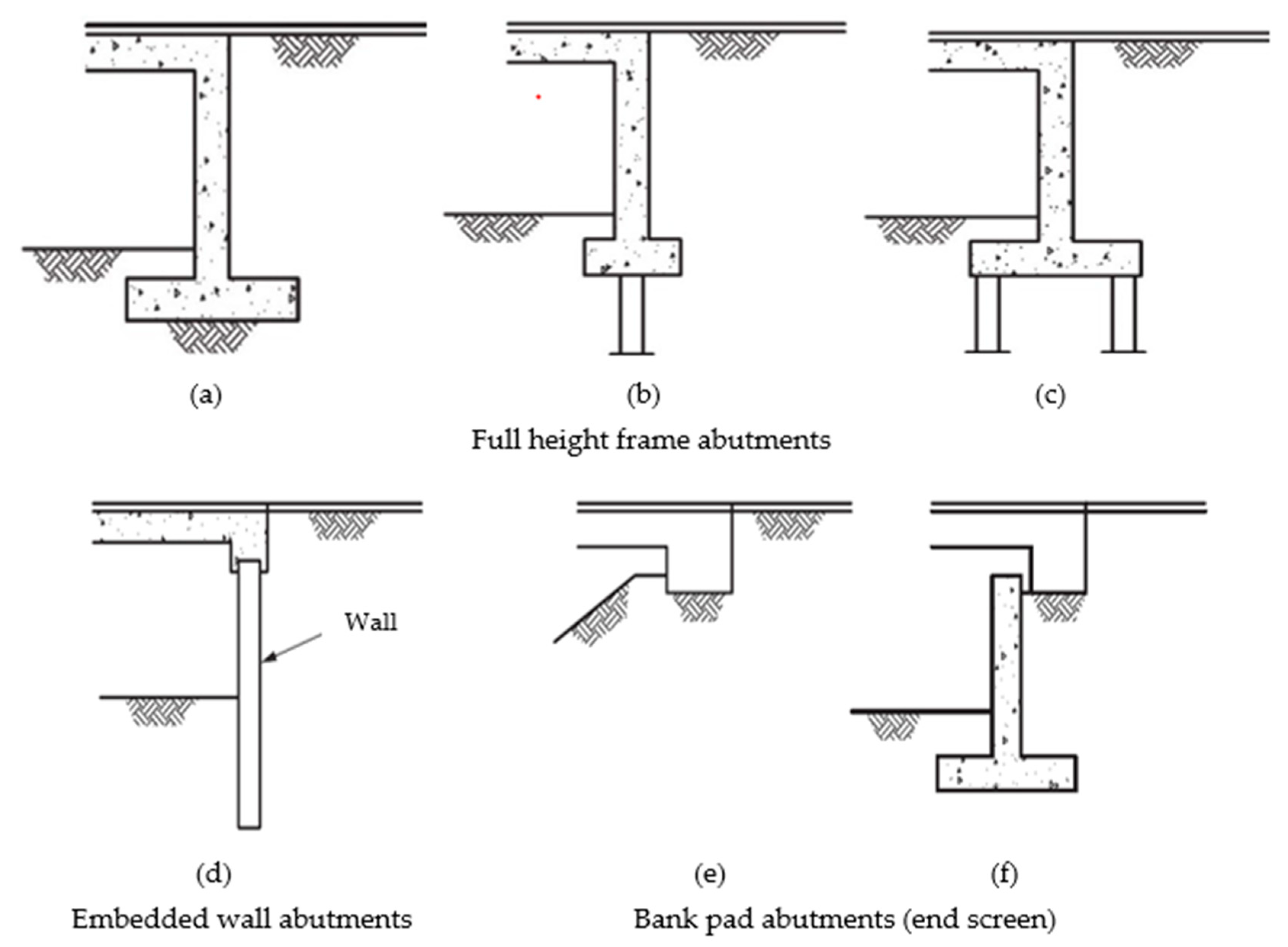
Figure 1. Types of integral and semi-integral abutments [25]. Reprinted from PD 6694-1:2011+A1:2020. Recommendations for the Design of Structures Subject to Traffic Loading to BS EN 1997-1:2004+A1:2013; BSI (British Standard International): London, UK, 2020 (Copyright permission BSI 2020).
Applsci 11 07131 g001aApplsci 11 07131 g001b
Figure 2. Earth pressure distribution on the bank pad abutment.
Applsci 11 07131 g002
Figure 3. Earth pressure distribution on full height abutment: (a) rotationally rigid abutment; (b) rotationally flexible abutment; (c) earth pressure distribution.
Applsci 11 07131 g003
Figure 4. (a) partial isolation technique; (b) full isolation technique.
Applsci 11 07131 g004
Figure 5. Orientation of the H-pile: (a) pile bent along the weak axis; (b) pile bent along the strong axis.
Applsci 11 07131 g005
Figure 6. Sleeves around the piles.
Applsci 11 07131 g006
Publisher’s Note: MDPI stays neutral with regard to jurisdictional claims in published maps and institutional affiliations.