
Experimental Study of the Effects of Torsional Loading on Three Types of Nickel-Titanium Endodontic Instruments

 ,
,  , ,
, ,  ,
,  ,
, 
Abstract
:1. Introduction
2. Materials and Methods
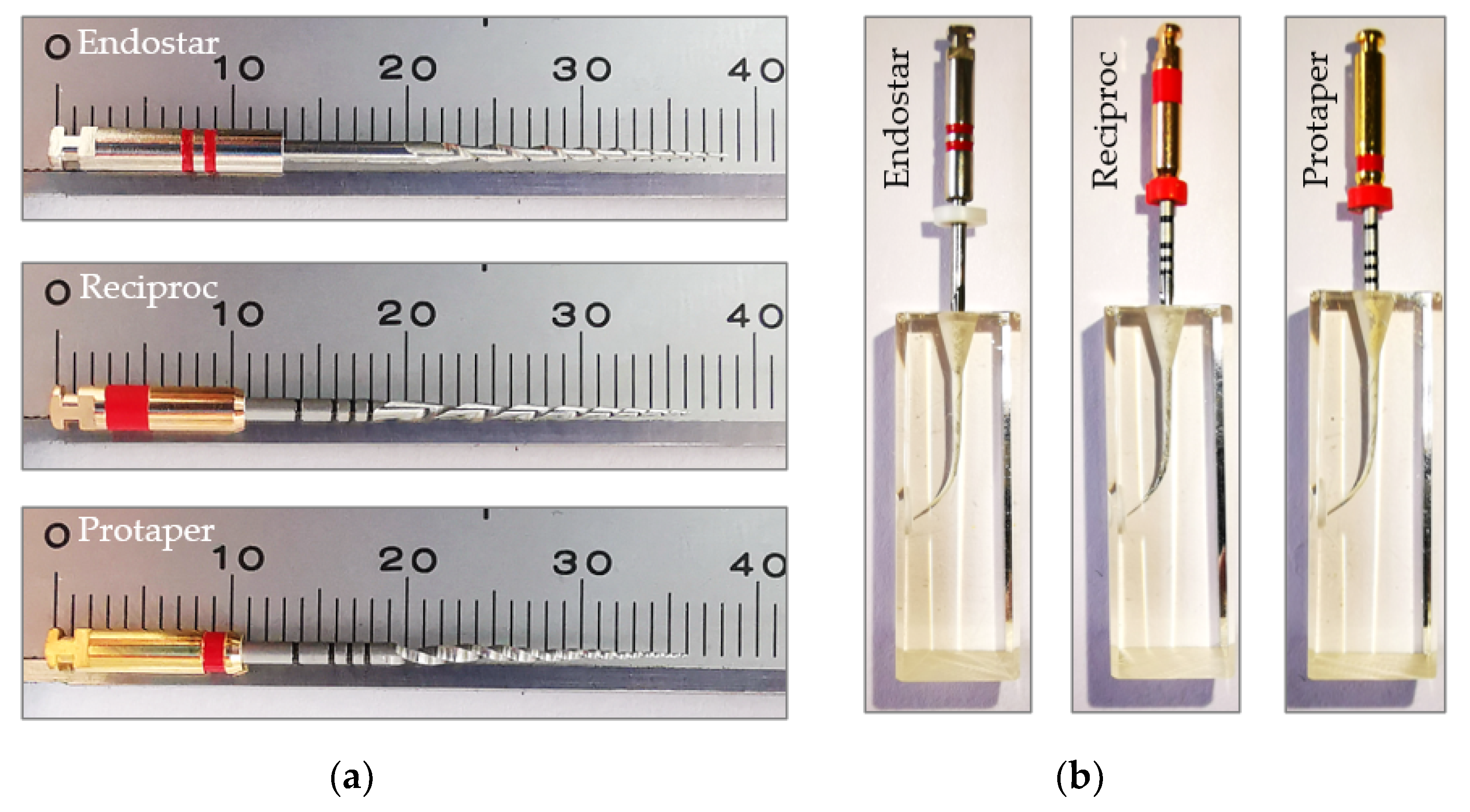
- Group Endostar consists of E3 Endostar (Endostar, Poldert Co. Ltd., Warsaw, Poland) instruments.
- Group Reciproc consists of Reciproc R25 (VDW, Munchen, Germany) instruments.
- Group Protaper consists of Protaper Next X2 (Dentsply Maillefer, Ballaigues, Switzerland) instruments.
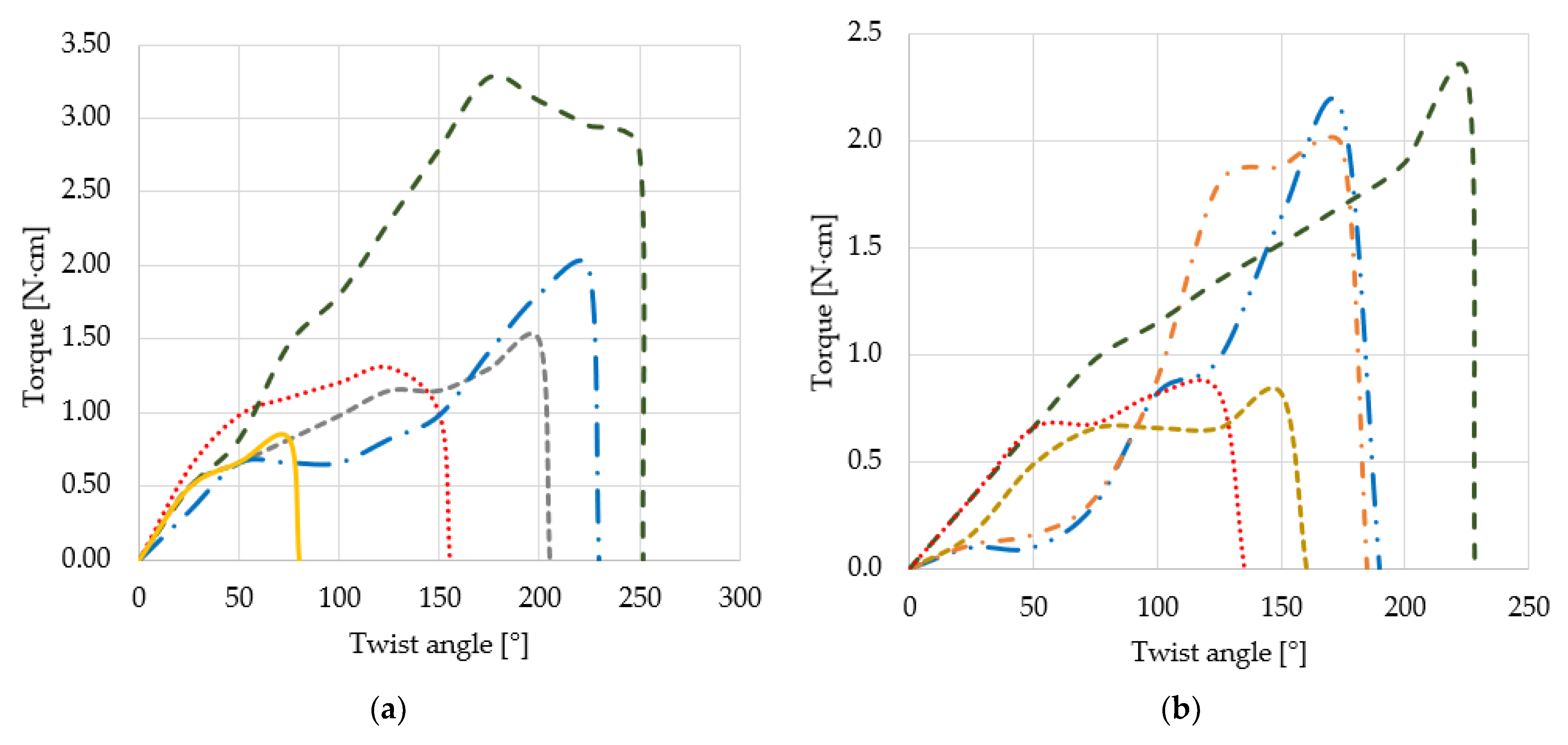
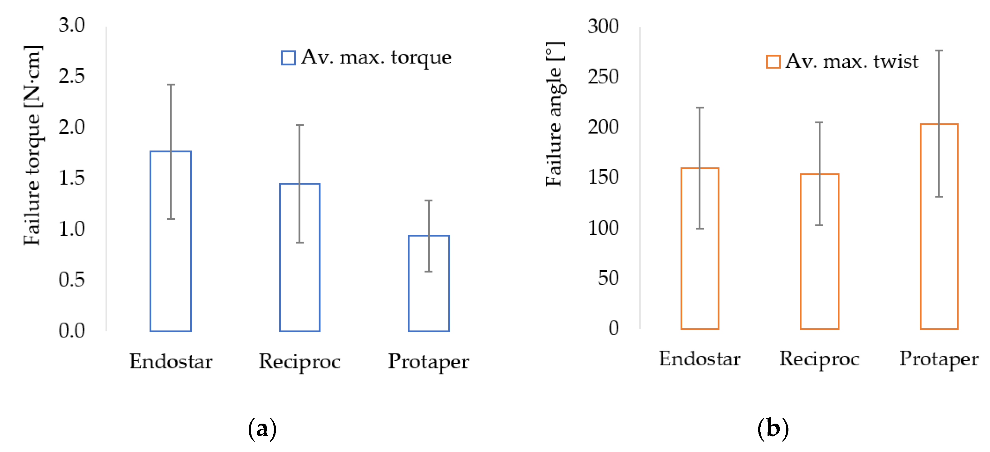
3. Results
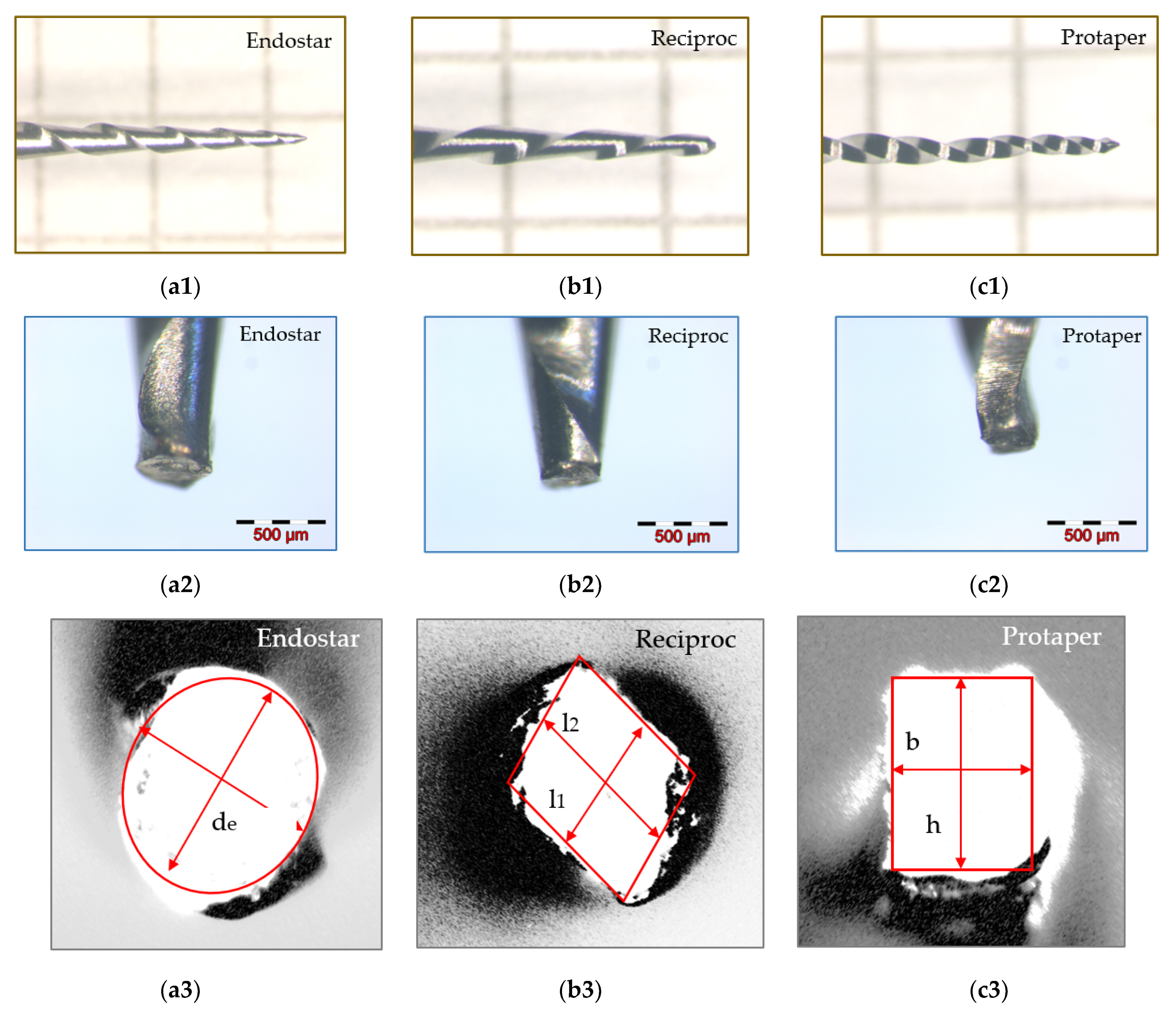
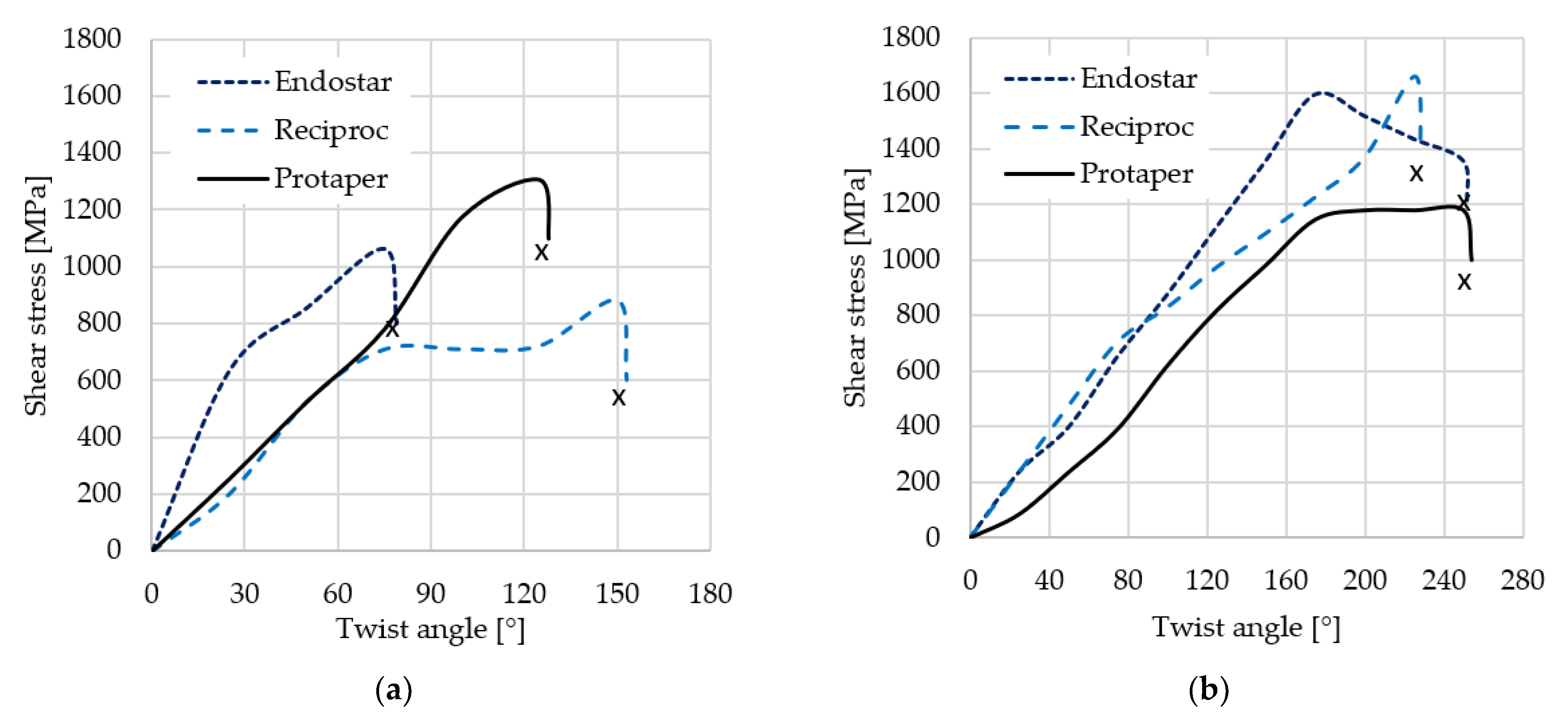
4. Discussion
5. Conclusions
- The torsional behavior of all three types of instruments included in the present study is similar from the point of view of the maximum tangential stresses recorded.
- The fractographic analysis of the sections indicated that the failure mode of all three types of instruments is similar.
- From the perspective of withstanding torsional loads, the cross-sectional shape of E instruments is superior to the other two considered in the comparison.
- By improving the qualities of NiTi alloys, the deficiency due to the shape of the instrument design (i.e., cross-section) can be partially compensated.
- While the more robust instruments (Type E) appear to be more torsion-resistant, the others compensate through higher elasticity due to the M-wire alloy.
Author Contributions
Funding
Data Availability Statement
Acknowledgments
Conflicts of Interest
References
- Dagna, A.; Poggio, C.; Beltrami, R.; Chiesa, M.; Bianchi, S. Cyclic fatigue resistance of three NiTi single-file systems after immersion in EDTA. Dentistry 2013, 4, 1000184. [Google Scholar]
- Pirani, C.; Cirulli, P.P.; Chersoni, S.; Micele, L.; Ruggeri, O.; Prati, C. Cyclic fatigue testing and metallographic analysis of nickel-titanium rotary instruments. JOE 2011, 37, 1013–1016. [Google Scholar] [CrossRef]
- Cheung, G.S.; Liu, C.S.Y. A retrospective study of endodontic treatment outcome between nickel—Titanium rotary and stainless steel hand filing techniques. J. Endod. 2009, 35, 938–943. [Google Scholar] [CrossRef]
- Walia, H.M.; Brantley, W.A.; Gerstein, H. An initial investigation of the bending and torsional properties of nitinol root canal files. J. Endod. 1988, 14, 346–351. [Google Scholar] [CrossRef]
- Shen, Y.; Riyahi, A.M.; Campbell, L.; Zhou, H.; Du, T.; Whang, Z.; Qian, W.; Haapasalo, M. Effect of a combination of torsional and cyclic fatigue preloading on the fracture behavior of K3 and K3XF instruments. J. Endod. 2015, 41, 526–530. [Google Scholar] [CrossRef]
- Cheung, G.S. Instrument fracture: Mechanisms, removal of fragments, and clinical outcomes. Endod. Top. 2009, 16, 1–26. [Google Scholar] [CrossRef]
- Pedull`a, E.; Grande, N.M.; Plotino, G.; Palermo, F.; Gambarini, G.; Rapisarda, E. Cyclic fatigue resistance of two reciprocating nickel—titanium instruments after immersion in sodium hypo-chlorite. Int. Endod. J. 2013, 46, 155–159. [Google Scholar] [CrossRef]
- Sattapan, B.; Nervo, G.J.; Palamara, J.E.A.; Messer, H.H. Defects in rotary nickel-titanium files after clinical use. J. Endod. 2000, 26, 161–165. [Google Scholar] [CrossRef] [PubMed] [Green Version]
- Serene, T.P.; Adams, J.D.; Saxena, A. Nickel-Titanium Instruments. Applications in Endodontics; Ishiyaku EuroAmerica, Inc.: St. Louis, MO, USA, 1995. [Google Scholar]
- Ullmann, C.J.; Peters, O.A. Effect of cyclic fatigue on static fracture loads in ProTaper nickel-titanium rotary instruments. J. Endod. 2005, 31, 183–186. [Google Scholar] [CrossRef]
- Palma, P.J.; Messias, A.; Cerqueira, A.R.; Tavares, L.D.; Caramelo, F.; Roseiro, L.; Santos, J.M. Cyclic fatigue resistance of three rotary file systems in a dynamic model after immersion in sodium hypochlorite. Odontology 2019, 107, 324–332. [Google Scholar] [CrossRef]
- Yum, J.; Cheung, G.S.P.; Park, J.K.; Hur, B.; Kim, H.C. Torsional strength and toughness of nickel-titanium rotary files. J. Endod. 2011, 37, 382–386. [Google Scholar] [CrossRef] [PubMed]
- Bhagabati, N.; Yadav, S.; Talwar, S. An in vitro cyclic fatigue analysis of different endodontic nickel-titanium rotary instruments. J. Endod. 2012, 38, 515–518. [Google Scholar] [CrossRef]
- Plotino, G.; Grande, N.M.; Melo, M.C.; Bahia, M.G.; Testarelli, L.; Gambar-ini, G. Cyclic fatigue of NiTi rotary instruments in a simulated apical abrupt curvature. Int. Endod. J. 2010, 43, 226–230. [Google Scholar] [CrossRef]
- Goldberg, M. Centering ability and influence of experience when using wave one single-file technique in simulated canals. Int. J. Dent. 2012, 2012, 206321. [Google Scholar] [CrossRef]
- Yufei, L.; Ning, Q.; Ming, X.; Chuyu, W.; Xiaoqing, Y. Comparison of shaping ability of five nickel-titanium rotary instruments in simulated curved canals. J. Dent. Oral Health 2017, 5, 2. [Google Scholar]
- Martin, B.; Zelada, G.; Varela, P.; Bahillo, J.G.; Magán, F.; Ahn, S.; Rodríguez, C. Factors influencing the fracture of nickel titanium rotary instruments. Int. Endod. J. 2003, 36, 262–266. [Google Scholar] [CrossRef] [PubMed]
- Alapati, S.; Brantley, W.A.; Iijima, M.; Clark, W.A.; Kovarik, L.; Buie, C.; Liu, J.; Ben Johnson, W. Metallurgical characterization of a new nickel-titanium wire for rotary endodontic instruments. J. Endod. 2009, 35, 1589–1593. [Google Scholar] [CrossRef]
- Ninan, E.; Berzins, D.W. Torsion and bending properties of shape memory and superelastic nickel-titanium rotary instruments. J. Endod. 2013, 39, 101–104. [Google Scholar] [CrossRef] [PubMed]
- Gambarini, G.; Grande, N.M.; Plotino, G.; Somma, F.; Garala, M.; De Luca, M.; Testarelli, L. Fatigue resistance of engine-driven rotary nickel-titanium instruments produced by new manufacturing methods. J. Endod. 2008, 34, 1003–1005. [Google Scholar] [CrossRef]
- Sekar, V.; Kumar, R.; Nandini, S.; Ballal, S.; Velmurugan, N. Assessment of the role of cross section on fatigue resistance of rotary files when used in reciprocation. Eur. J. Dent. 2016, 10, 541–545. [Google Scholar] [CrossRef] [Green Version]
- Medha, A.; Patil, S.; Hoshing, U.; Bandekar, S. Evaluation of forces generated on three different rotary files systems in apical third of root canal using finite element analysis. J. Clin. Diagn. Res. 2014, 8, 243–246. [Google Scholar] [CrossRef]
- Galal, M.; Hamdy, T.M. Evaluation of stress distribution in nickel-titanium rotary instruments with different geometrical designs subjected to bending and torsional load: A finite element study. Bull. Natl. Res. Cent. 2020, 44, 121. [Google Scholar] [CrossRef]
- Seracchiani, M.; Miccoli, G.; Di Nardo, D.; Zanza, A.; Cantore, M.; Gambarini, G.; Testarelli, L. Effect of flexural stress on torsional resistance of NiTi instruments. J. Endod. 2020, 3, 118. [Google Scholar] [CrossRef]
- Sarul, M.; Kozakiewicz, M.; Jurczyszyn, K. Surface evaluation of orthodontic wires using texture and fractal dimension analysis. Materials 2021, 14, 3688. [Google Scholar] [CrossRef] [PubMed]
- Altunbas, D.; Kutuk, B.; Kustarci, A. Shaping ability of reciprocating single-file and full-sequence rotary instrumentation systems in simulated curved canals. Eur. J. Dent. 2015, 9, 346–351. [Google Scholar] [CrossRef]
- Mazzoni, A.; Pacifici, A.; Zanza, A.; Giudice, A.D.; Reda, R.; Testarelli, L.; Gambarini, G.; Pacifici, L. Assessment of real-time operative torque during nickel–titanium instrumentation with different lubricants. Appl. Sci. 2020, 10, 6201. [Google Scholar] [CrossRef]
- Generali, L.; Malovo, A.; Bolelli, G.; Borghi, A.; La Rosa, G.R.M.; Puddu, P.; Lusvarghi, L.; Rota, A.; Consolo, U.; Pedullà, E. Mechanical properties and metallurgical features of new green NiTi reciprocating instruments. Materials 2020, 13, 3736. [Google Scholar] [CrossRef]
- Alovisi, M.; Dioguardi, M.; Carossa, M.; Troiano, G.; Domini, M.C.; Paolino, D.S.; Chiandussi, G.; Berutti, E. Working length transfer in the endodontic clinical practice: A comparative study. Appl. Sci. 2020, 10, 5824. [Google Scholar] [CrossRef]
- Dioguardi, M.; Crincoli, V.; Laino, L.; Alovisi, M.; Laneve, E.; Sovereto, D.; Raddato, B.; Zhurakivska, K.; Mastrangelo, F.; Ciavarella, D.; et al. Surface alterations induced on endodontic instruments by sterilization processes, analyzed with atomic force microscopy: A systematic review. Appl. Sci. 2019, 9, 4948. [Google Scholar] [CrossRef] [Green Version]
- Gambarini, G.; Miccoli, G.; Seracchiani, M.; Khrenova, T.; Donfrancesco, O.; D’Angelo, M.; Galli, M.; Di Nardo, D.; Testarelli, L. Role of the flat-designed surface in improving the cyclic fatigue resistance of endodontic NiTi rotary instruments. Materials 2019, 12, 2523. [Google Scholar] [CrossRef] [Green Version]
- Thu, M.; Ebihara, A.; Adel, S.; Okiji, T. Analysis of torque and force induced by rotary nickel-titanium instruments during root canal preparation: A systematic review. Appl. Sci. 2021, 11, 3079. [Google Scholar] [CrossRef]
- Endal, U.; Shen, Y.; Knut, A.; Gao, Y.; Haapasalo, M. A high-resolution computed tomographic study of changes in root canal isthmus area by instrumentation and root filling. J. Endod. 2011, 37, 223–227. [Google Scholar] [CrossRef]
- Kim, J.Y.; Cheung, G.S.; Park, S.H.; Ko, D.C.; Kim, J.W.; Kim, H.C. Effect from cyclic fatigue of nickel-titanium rotary files on torsional resistance. J. Endod. 2012, 38, 527–530. [Google Scholar] [CrossRef] [PubMed]
- Campbell, L.; Shen, Y.; Zhou, H.M.; Haapasalo, M. Effect of fatigue on torsional failure of nickel-titanium controlled memory instruments. J. Endod. 2014, 40, 562–565. [Google Scholar] [CrossRef] [Green Version]
- Bahia, M.G.; Melo, M.C.; Buono, V.T. Influence of cyclic torsional loading on the fatigue resistance of K3 instruments. Int. Endod. J. 2008, 10, 883–891. [Google Scholar] [CrossRef] [PubMed]
- Cheung, G.S.; Oh, S.H.; Ha, J.H.; Kim, S.K.; Park, S.H.; Kim, H.C. Effect of torsional loading of nickel—Titanium instruments on cyclic fatigue resistance. J. Endod. 2013, 39, 1593–1597. [Google Scholar] [CrossRef]
- Galvao Barbosa, F.O.; Ponciano Gomes, J.A.; Pimenta de Araujo, M.C. Influence of previous angular deformation on flexural fatigue resistance of K3 nickel-titanium rotary instruments. J. Endod. 2007, 33, 1477–1480. [Google Scholar] [CrossRef] [PubMed]
- Sousa, J.; Basto, J.; Roseiro, L.; Messias, A.; dos Santos, J.M.; Palma, P. Avaliação da fadiga cíclica de 3 sistemas de limas utilizadas em instrumentação mecanizada. Revista Portuguesa de Estomatologia, Medicina Dentária e Cirurgia Maxilofacial 2015, 56, 239–245. [Google Scholar] [CrossRef] [Green Version]
- La Rosa, G.R.M.; Shumakova, V.; Isola, G.; Indelicato, F.; Bugea, C.; Pedullà, E. Evaluation of the cyclic fatigue of two single files at body and room temperature with different radii of curvature. Materials 2021, 14, 2256. [Google Scholar] [CrossRef]
- Melo, M.C.; Pereira, E.S.; Viana, A.C.; Fonseca, A.M.; Buono, V.T.; Bahia, M.G. Dimensional characterization and mechanical behaviour of K3 rotary instruments. Int. Endod. J. 2008, 41, 329–338. [Google Scholar] [CrossRef]
- Pedullà, E.; Lo Savio, F.; Boninelli, S.; Plotino, G.; Grande, N.M.; La Rosa, G. Torsional and cyclic fatigue resistance of a new nickel-titanium instrument manufactured by electrical discharge machining. J. Endod. 2016, 42, 156–159. [Google Scholar] [CrossRef]
- Alcalde, M.P.; Tanomaru-Filho, M.; Bramante, C.M.; Duarte, M.A.; Guerreiro-Tanomaru, J.M.; Camilo-Pinto, J.; Só, M.V.R.; Vivan, R.R. Cyclic and torsional fatigue resistance of reciprocating single files manufactured by different nickel-titanium alloys. J. Endod. 2017, 43, 1186–1191. [Google Scholar] [CrossRef] [Green Version]
- Bahia, M.G.; Melo, M.C.; Buono, V.T. Influence of simulated clinical use on the torsional behavior of nickel-titanium rotary endodontic instruments. Oral Surg. Oral Med. Oral Pathol. Oral Radiol. Endod. 2006, 101, 675–680. [Google Scholar] [CrossRef]
- Alcalde, M.P.; Duarte, M.A.; Bramante, C.M.; Tanomaru-Filho, M.; Vasconcelos, B.C.; Só, M.V.; Vivan, R.R. Torsional fatigue resistance of pathfinding instruments manufactured from several nickel-titanium alloys. Int. Endod. J. 2018, 51, 697–704. [Google Scholar] [CrossRef]
- Berutti, E.; Negro, A.R.; Lendini, M.; Pasqualini, D. Influence of manual preflaring and torque on the failure rate of ProTaper rotary instruments. J. Endod. 2004, 30, 228–230. [Google Scholar] [CrossRef] [Green Version]
- Goo, H.J.; Kwak, S.W.; Ha, J.H.; Pedullà, E.; Kim, H.C. Mechanical properties of various heat-treated nickel-titanium rotary instruments. J. Endod. 2017, 43, 1872–1877. [Google Scholar] [CrossRef]
- Viana, A.C.; Melo, M.C.C.; Bahia, M.G.A.; Lopes Buono, V.T. Relationship between flexibility and physical, chemical, and geometric characteristics of rotary nickel-titanium instruments. Oral Surg. Oral Med. Oral Pathol. Oral Radiol. Endod. 2010, 110, 527–533. [Google Scholar] [CrossRef]
- Baek, S.H.; Lee, C.J.; Versluis, A.; Kim, B.M.; Lee, W.; Kim, H.C. Comparison of torsional stiffness of nickel-titanium rotary files with different geometric characteristics. J. Endod. 2011, 37, 1283–1286. [Google Scholar] [CrossRef] [PubMed]
- Peters, O.A.; Barbakow, F. Dynamic torque and apical forces of ProFile.04 rotary instruments during preparation of curved canals. Int. Endod. J. 2002, 35, 379–389. [Google Scholar] [CrossRef] [PubMed]
- Berutti, E.; Chiandussi, G.; Gaviglio, I.; Ibba, A. Comparative analysis of torsional and bending stresses in two mathematical models of nickel-titanium rotary instruments: ProTaper versus ProFile. J. Endod. 2003, 29, 15–19. [Google Scholar] [CrossRef]
- Kim, H.C.; Kwak, S.W.; Cheung, G.S.; Ko, D.H.; Chung, S.M.; Lee, W.C. Cyclic fatigue and torsional resistance of two new nickel-titanium instruments used in reciprocation motion: Reciproc versus Wave One. J. Endod. 2012, 38, 541–544. [Google Scholar] [CrossRef] [Green Version]
- Yared, G. Canal preparation using only one NiTi rotary instrument: Preliminary observations. Int. Endod. J. 2008, 41, 339–344. [Google Scholar] [CrossRef]
- Kim, H.C.; Yum, J.; Hur, B.; Cheung, G.S. Cyclic fatigue and fracture characteristics of ground and twisted nickel-titanium rotary files. J. Endod. 2010, 36, 147–152. [Google Scholar] [CrossRef]
- Drukteinis, S.; Peciuliene, V.; Bendinskaite, R.; Brukiene, V.; Maneliene, R.; Rutkunas, V. Shaping and Centering Ability, Cyclic fatigue resistance and fractographic analysis of three thermally treated NiTi endodontic instrument systems. Materials 2020, 13, 5823. [Google Scholar] [CrossRef]
- Hutiu, G.; Duma, V.-F.; Demian, D.; Bradu, A.; Podoleanu, A. Surface imaging of metallic material fractures using optical coherence tomography. Appl. Opt. 2014, 53, 5912–5916. [Google Scholar] [CrossRef]
- Hutiu, G.; Duma, V.-F.; Demian, D.; Bradu, A.; Podoleanu, A. Assessment of ductile, brittle, and fatigue fractures of metals using optical coherence tomography. Metals 2018, 8, 117. [Google Scholar] [CrossRef] [Green Version]
- Erdelyi, R.-A.; Duma, V.-F.; Sinescu, C.; Dobre, G.; Bradu, A.; Podoleanu, A. Dental diagnosis and treatment assessments: Between X-rays radiography and optical coherence tomography. Materials 2020, 13, 4825. [Google Scholar] [CrossRef]
- Erdelyi, R.-A.; Duma, V.-F.; Sinescu, C.; Dobre, G.; Bradu, A.; Podoleanu, A. Optimization of X-ray investigations in dentistry using optical coherence tomography. Sensors 2021, 21, 4554. [Google Scholar] [CrossRef]


| Sample | Group Endostar | Group Reciproc | Group Protaper | |||
|---|---|---|---|---|---|---|
| Tmax (N · cm) | θmax (°) | Tmax (N · cm) | θmax (°) | Tmax (N · cm) | θmax (°) | |
| 1 | 1.30 | 125 | 2.13 | 175 | 0.82 | 275 |
| 2 | 1.48 | 200 | 0.82 | 150 | 0.82 | 250 |
| 3 | 0.82 | 75 | 1.97 | 175 | 1.00 | 250 |
| 4 | 3.28 | 175 | 2.30 | 225 | 1.80 | 250 |
| 5 | 1.97 | 225 | 0.82 | 125 | 0.82 | 125 |
| Group Endostar | Group Reciproc | Group Protaper | ||||
|---|---|---|---|---|---|---|
| Mean | Standard Deviation | Mean | Standard Deviation | Mean | Standard Deviation | |
| τmax (MPa) | 1306.8 | 301.9 | 1160.0 | 473.0 | 1050.6 | 287.4 |
| θmax (°) | 161.2 | 60.2 | 154.2 | 51.0 | 204.2 | 82.8 |
Publisher’s Note: MDPI stays neutral with regard to jurisdictional claims in published maps and institutional affiliations. |
© 2021 by the authors. Licensee MDPI, Basel, Switzerland. This article is an open access article distributed under the terms and conditions of the Creative Commons Attribution (CC BY) license (https://creativecommons.org/licenses/by/4.0/).
Share and Cite
Boscornea-Pușcu, A.-S.; Orel, L.; Velea-Barta, O.-A.; Horhat, R.M.; Negruțiu, M.-L.; Nica, L.M.; Duma, V.-F.; Stoia, D.I.; Opriș, C.; Sinescu, C. Experimental Study of the Effects of Torsional Loading on Three Types of Nickel-Titanium Endodontic Instruments. Appl. Sci. 2021, 11, 7224. https://doi.org/10.3390/app11167224
Boscornea-Pușcu A-S, Orel L, Velea-Barta O-A, Horhat RM, Negruțiu M-L, Nica LM, Duma V-F, Stoia DI, Opriș C, Sinescu C. Experimental Study of the Effects of Torsional Loading on Three Types of Nickel-Titanium Endodontic Instruments. Applied Sciences. 2021; 11(16):7224. https://doi.org/10.3390/app11167224
Chicago/Turabian StyleBoscornea-Pușcu, Andreea-Simona, Laura Orel, Oana-Alexandra Velea-Barta, Razvan Mihai Horhat, Meda-Lavinia Negruțiu, Luminița Maria Nica, Virgil-Florin Duma, Dan Ioan Stoia, Carmen Opriș, and Cosmin Sinescu. 2021. "Experimental Study of the Effects of Torsional Loading on Three Types of Nickel-Titanium Endodontic Instruments" Applied Sciences 11, no. 16: 7224. https://doi.org/10.3390/app11167224
APA StyleBoscornea-Pușcu, A.-S., Orel, L., Velea-Barta, O.-A., Horhat, R. M., Negruțiu, M.-L., Nica, L. M., Duma, V.-F., Stoia, D. I., Opriș, C., & Sinescu, C. (2021). Experimental Study of the Effects of Torsional Loading on Three Types of Nickel-Titanium Endodontic Instruments. Applied Sciences, 11(16), 7224. https://doi.org/10.3390/app11167224