Abstract
This research presents the theoretical and experimental studies for cylindrical and conical periodic structures to control longitudinal wave motion. Many relevant researches exist to stop and pass a certain frequency wave without active devices with periodic structures called metamaterials. To modify or control longitudinal wave propagation, i.e., passing or blocking mechanical wave within specific frequency ranges, repeated mass-spring systems or metamaterials can be applied. By integrating a few identical structural components to form a whole structure, it is possible to make a mechanical filter for wave propagation. Most studies rely on straight bar with cylindrical structure. Thus, with a unit cell that have a cylindrical and conical structure, this research presents the extensions toward the studies of the wave motions for straight and curved bars with finite element simulations and experiment studies. The results show that the hybrid cylindrical and conical periodic structures can be effective in terms of wave motion control and stiffness.
1. Introduction
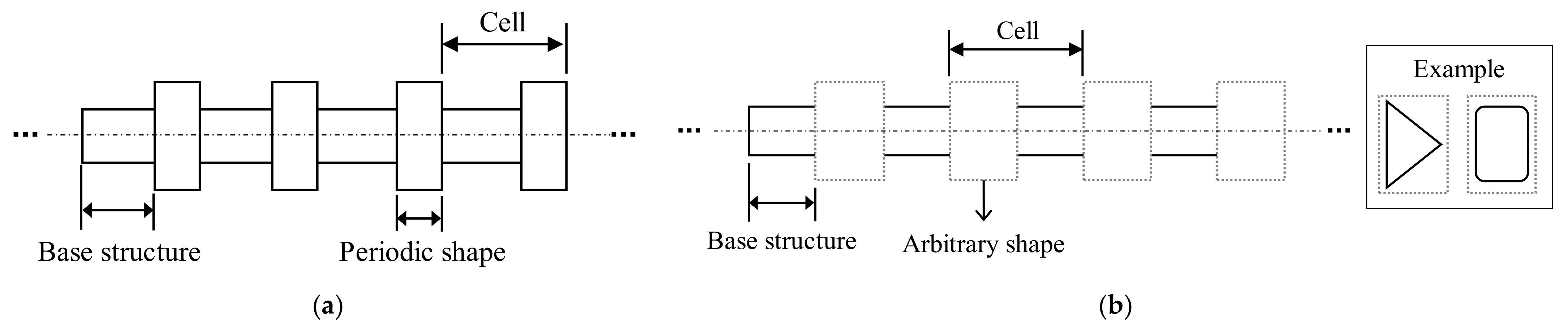
This research conducts numerical analysis and experiments for the longitudinal wave of mechanical metamaterials with the cylindrical and the conical metamaterials elements shown in Figure 1. By integrating a few identical structural components to form a whole structure, it is possible to make a mechanical filter for wave propagation. Compared with the conventional vibration absorber consisting of dynamic absorbers attached to a main structure, the metamaterials are made by only joining a few periodic units to form a whole structure. Due to their periodicity, the mechanical metamaterials become mechanical filters for wave propagation. Within specific frequency bands defined by the dynamic characteristics (eigenfrequencies and band gaps) of periodic elements, wave propagations can be controlled. This research presents an engineering approach to control the longitudinal wave propagations with the cylindrical and the conical metamaterials shown in Figure 1.
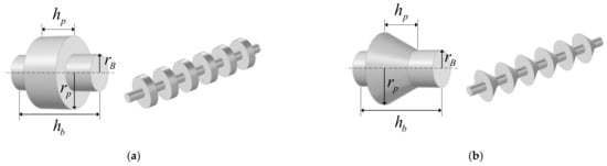
Figure 1.
A representation of the periodic structure cell (a) Cylindrical metamaterials and (b) cone shape metamaterials.
The periodic structures are constructed with repeated parts or components to attain some special dynamic characteristics as shown in Figure 1 and Figure 2. They are continuously connected to form overall structures. Because of their periodic characteristics, these periodic structures exhibit unique dynamic properties that can serve as mechanical filters for wave propagation; the longitudinal wave has this characteristic of passing a certain frequency band(pass band) and cannot pass a specific frequency band(stop band) in a periodic structure. The characteristics of longitudinal waves can be used in various fields such as solid-state physics, X-ray, optics, and wave mechanics, based on the study of Brillouin (1953) [1]. Our research is also based on the Brillouin theory for predicting the band gaps of passive periodic structure with geometrical or material discontinuities. In quantum mechanics, Kronig and Penney mentioned the classical paper that underpinned the modern theory of classical theory for the first time [2]. Studies of elastic wave and acoustic wave have been reported with the same periodic structure regularly arranged in homogeneous materials [3], and the wave propagation theory is one-dimension from a medium composed of the same unit cell. Research has been carried out to provide applications of theoretically approachable waves in periodic media and extended into various physical fields [4]. Study have also been conducted to prove that there are no frequency intervals for propagating elastic waves in many mechanical grid structures such as the membrane, atomic triangle, atomic rectangle, and honeycomb [5]. Research has been conducted on the relationship between the frequency at the boundary of the propagation domain from a single coupling periodic system and the natural frequency of the individual elements constituting the system. Furthermore, the general theory on propagation of harmonic wave in one-dimensional periodic systems with multiple coupling between adjacent periodic elements has been presented [6,7,8]. In addition, the vibration problem of the periodic system can be analyzed efficiently by using of the transfer matrix method [9,10]. A study of periodic structures consisting of beam and plate was conducted [11]. Those studies have been conducted to analyze and predict forced wave motion in continuous periodic structures, and an appropriate way to use Floquet principle to predict the sound emitted from beams, plates, and cylinders has now been introduced [12]. The method has been presented using the finite element method in connection with the variation of the imaginary part of the radio constant where the natural frequency of the periodic structure is known to be propagation constant [13]. Moreover, the study was conducted to investigate the vibrational response of a finite periodic structure with harmonic loading and to derive the dispersion relation from the acoustic wave equation [14,15].

Figure 2.
The general concept of periodic structures. (a) Generally known periodic structure and (b) Use various shapes as a periodic structure.
The periodicity of the passive structure with the geometrical and the material discontinuities influences the wave propagation predicted by the Brillouin theory. As a theory assumes the discontinuities and resonances among periodic structure, it can be applied to wave motion found in nature such as optical metamaterials, the wave mechanics of the spinning electrons, and the mechanical metamaterials. As a result, research on the shape of the periodic structure has been advanced. In the case of a general periodic structure used as a mechanical filter, it is classified into passive and active periodic structure. Existing passive periodic structures exhibit intrinsic dynamic properties that act as mechanical filters for wave propagation. The harmonic analysis solution has been proposed with rectangular elastic rods of arbitrary aspect ratio [16]. The research on the longitudinal wave propagation of exponentially tapered bars was studied from theoretical and experimental point of view [17]. Additionally, the study of longitudinal wave control was advanced using the periodic structure with a conical shape of a different size and array [18]. It is known that changes in the cone’s cross section cause wave dispersion, that conical rods are commonly used as high-pass filters, and that blocked frequencies vary with cone angle [19]. In the case of longitudinal waves of different cross-sections, inhomogeneities are characterized by density and elastic modulus [20]. To enhance the performance of the passive metamaterials, it is possible to add active materials. As for active periodic structures, the structure with active control was studied with the focus on the adjustment of spectral widths and positions of structural vibration and stop band [21]. The longitudinal wave transmission can be controlled by shape memory inserts which are periodically arranged adjustable properties according to load and active periodic structures that cause impedance mismatches [22]. Metamaterials based on liquid-crystal layers were studied in [23,24].
Some sensitive mechanical device, audio, and electrical devices require vibration isolators to prevent vibration transmission among their components. To prevent vibration transmission, the isolation of components may be the best, but it loses the mechanical supporting function. The cylindrical shape metamaterials were commonly used, and the conical spikes were also used. The conical spikes were used to isolate environmental vibration from mechanical and electronic devices. It was reported that the single cone as an isolator and that the magnitude of the transmitted acceleration can be further reduced compared with a cylindrical shape isolator [18]. In this paper, we investigate the wave motions in cylindrical metamaterials, conical metamaterials, and the combined metamaterials. Tongele investigated the wave motion in conical periodic structure and Graff investigated that the wave dispersion can be induced by varying the cross section [18,19]. The cutoff frequency is dependent on the profiles of the conical shape. However, there is no research regarding the longitudinal wave motion of the combined type of cylindrical and conical metamaterials. In addition, this research studies the wave motions of the curved rod with the cylindrical and the conical metamaterials to extend the usage of the metamaterials.
This research conducts the theoretical and experimental studies for the mechanical metamaterials for longitudinal wave in which the displacements show the same direction or the opposite direction to the propagation direction of wave. This research is interested in the metamaterials controlling the longitudinal wave. For a periodically repeating unit, cylindrical and conical structures are exploited for longitudinal wave in the straight rod and the curved rod. The research on how to control the longitudinal wave in a straight beam using metamaterials has been mainly conducted. However, there are few researches conserving the longitudinal wave in a curved structure. Compared to a straight beam, it is hard to manufacture the repeating unit to control the longitudinal wave and the transverse wave. To address this issue, this research conducts some numerical and experimental studies.
This paper is organized as follows. Section 2 describes the basic equations for the metamaterials with repeating cylinder and cone structures. Section 3 presents some numerical and experimental data of the mechanical metamaterials for longitudinal waves. Section 4 presents the conclusions and suggests future research topics.
2. Wave Motion in Metamaterials
This section introduces the theory of wave motion in periodic structure and the finite element simulation considering the periodicity.
2.1. Wave Motion in Periodic Structure
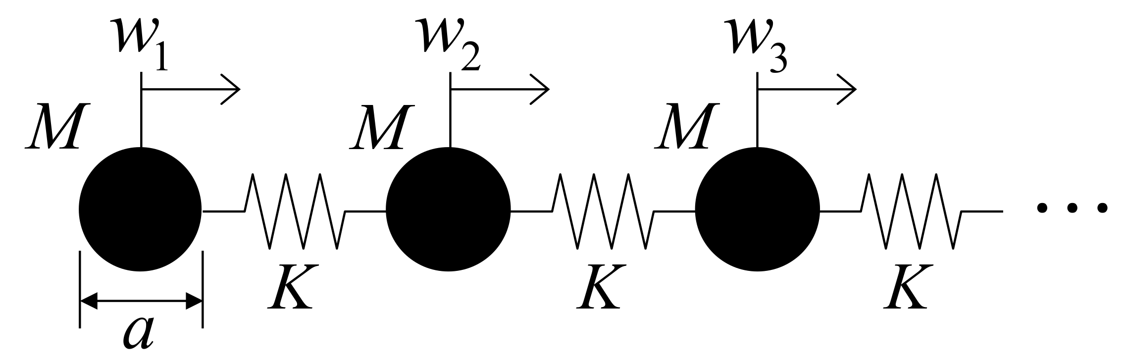
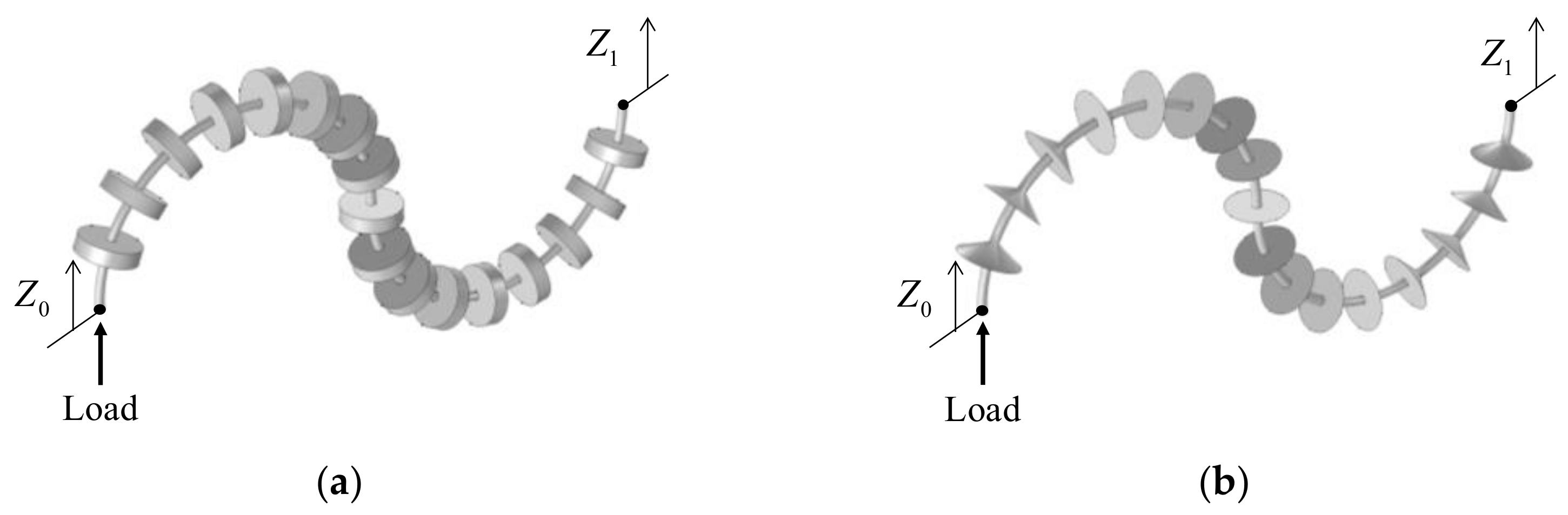
In order to investigate the effects of mass and stiffness for the longitudinal wave in the rod, the general modal solution for the displacement of a 1D periodic structure having lattice constant, as shown in Figure 3, can be considered by harmonic modulation of a a-periodic field wp as follows:
where is an angular frequency and k is a wave number in the wave propagating direction. It should be noted that the mass effect of the narrow area in the periodic cylindrical or conical shape influences the wave dispersion phenomenon. With the Bloch–Floquet condition, the following dynamic system can be obtained.
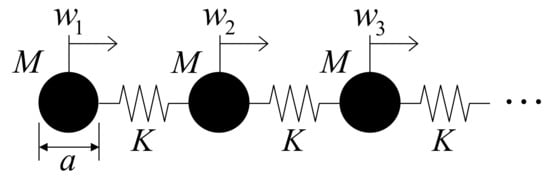
Figure 3.
A repeating mass-spring system for longitudinal wave motion.
The stiffness matrix K is complex and dependent on wave number k. Due to the periodicity of structure, the representative unit cell with a length equal to lattice constant a is modeled. Finally, the modal response of unit cell is obtained by and the eigenvalue analysis for non-trivial solutions is formulated as follows:
where Kp and Mp are reduced tangent stiffness and mass matrices obtained after applying the periodic boundary condition. The gradient of eigenvalues and wave number k is determined. Principally, k can have any value but due to periodicity in the Bloch–Floquet condition, it can be limited to the first Brillouin zone (a uniquely defined primitive cell in reciprocal space). and further to irreducible Brillouin zone, .
2.2. Finite Element Analysis of Cylindrical and Conical Metamaterials
To analyze the dynamic characteristics such as frequency response function, eigenvalues and band gaps of periodic structures, i.e., the finite element analysis, has been conducted. In case of the simple geometry, i.e., representative mass and stiffness system, its eigenfrequencies can be theoretically derived and the frequency response function to external loads can be computed. With the simple geometry and the Floquet boundary condition (the periodic boundary condition), the eigenvalue problem of the system can be solved to determine the band gaps. With a manifold geometry, however, it is not easy and a numerical analysis, such as the finite element method, should be carried out to investigate. In this study, the finite element simulations are conducted to investigate the dynamic characteristics of the cylindrical and the conical metamaterials.
Without the loss of generality, the Newton’s second equation is solved for the time varying response of linear solid structure with time varying force .
where M, C, and K are the mass matrix, damping matrix, and stiffness matrix with appropriate boundary conditions, respectively. The time-varying displacements, velocities, and accelerations of a structure are denoted . For the frequency response analysis, the following harmonic excitation is assumed.
By assuming the harmonic motion and loading, the following eigenvalue problem can be obtained.
where the eigenvalue is denoted by . With the Bloch–Floquet theory, the periodic conditions are imposed as follows:
where the displacements at the left side, the right side and the internal domain are denoted by , and , respectively. The transformation matrix is denoted by T. To obtain the dispersion relationship, we multiply the transpose of the transformation matrix to form the dynamic stiffness matrix as follows:
2.3. Periodic Cylindrical and Conical Metamaterials
To attenuate the longitudinal wave, this research considers the cylindrical and the conical metamaterials shown in Figure 1. There are narrow and thick necks in the periodic structures in Figure 1. From a metamaterials point of view, the narrow necks correspond to the stiffnesses and the thick necks correspond to the masses. The eigenfrequencies of the repeated periodic structures generate the band gap for the longitudinal wave in the periodic structures. Depending on the geometrical values, the band gaps can be varied. Due to the difficulties of the theoretical approach, the finite element analysis is employed in this research.
3. Numerical and Experiment Results of Metamaterials
To show the validity and application of the present periodic metamaterials in attenuating longitudinal wave, this section presents several numerical studies and experiment results of periodic structures. The band gap phenomena of straight and curved beams with cylindrical metamaterials, conical metamaterials, and combining metamaterials are investigated. The effects of the geometries on the band gap phenomena are also investigated. Bars are made of aluminum 2011 (Young’s modulus: 66 GPa, Density: 2823 kg/m3, Poisson’s ratio: 0.3), and the cylindrical and the conical metamaterials are made of aluminum 7075 (Young’s modulus: 71 GPa, density: 2810 kg/m3, Poisson’s ratio: 0.33). The theoretical and experimental studies are carried out with aluminum as it is easy to make specimens. However, the present studies can be applied for general materials.
3.1. Straight Beam with Cylindrical Metamaterials
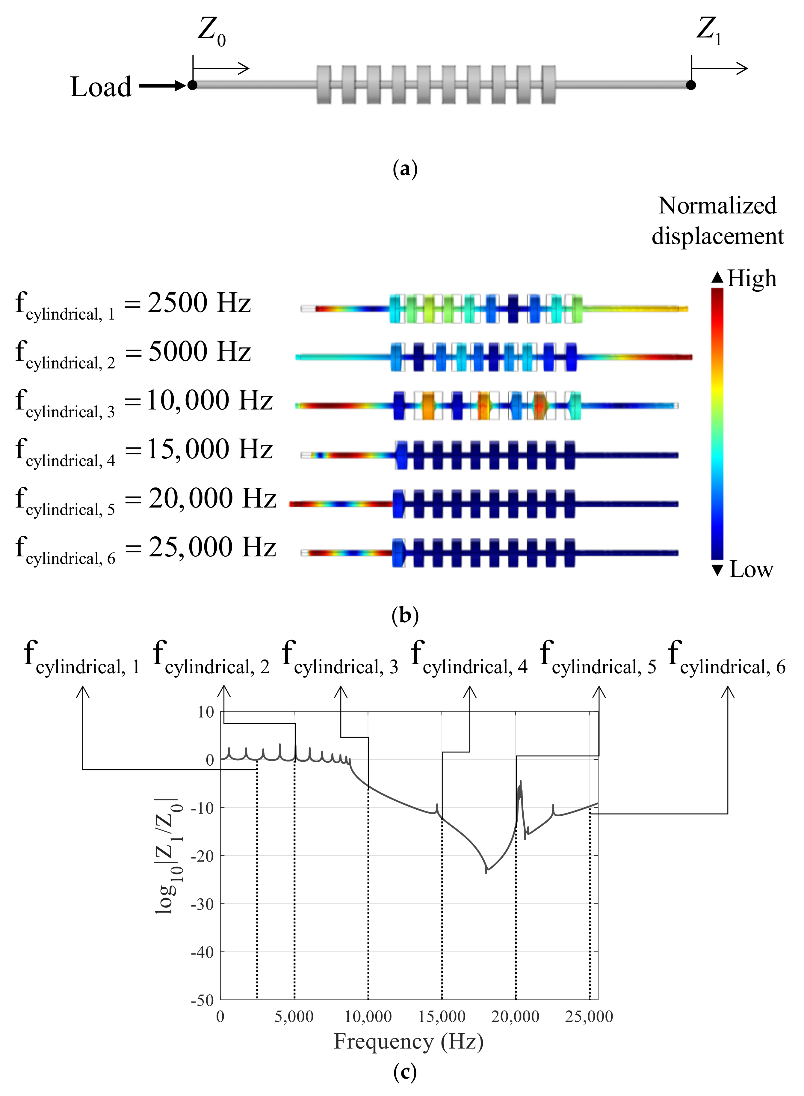
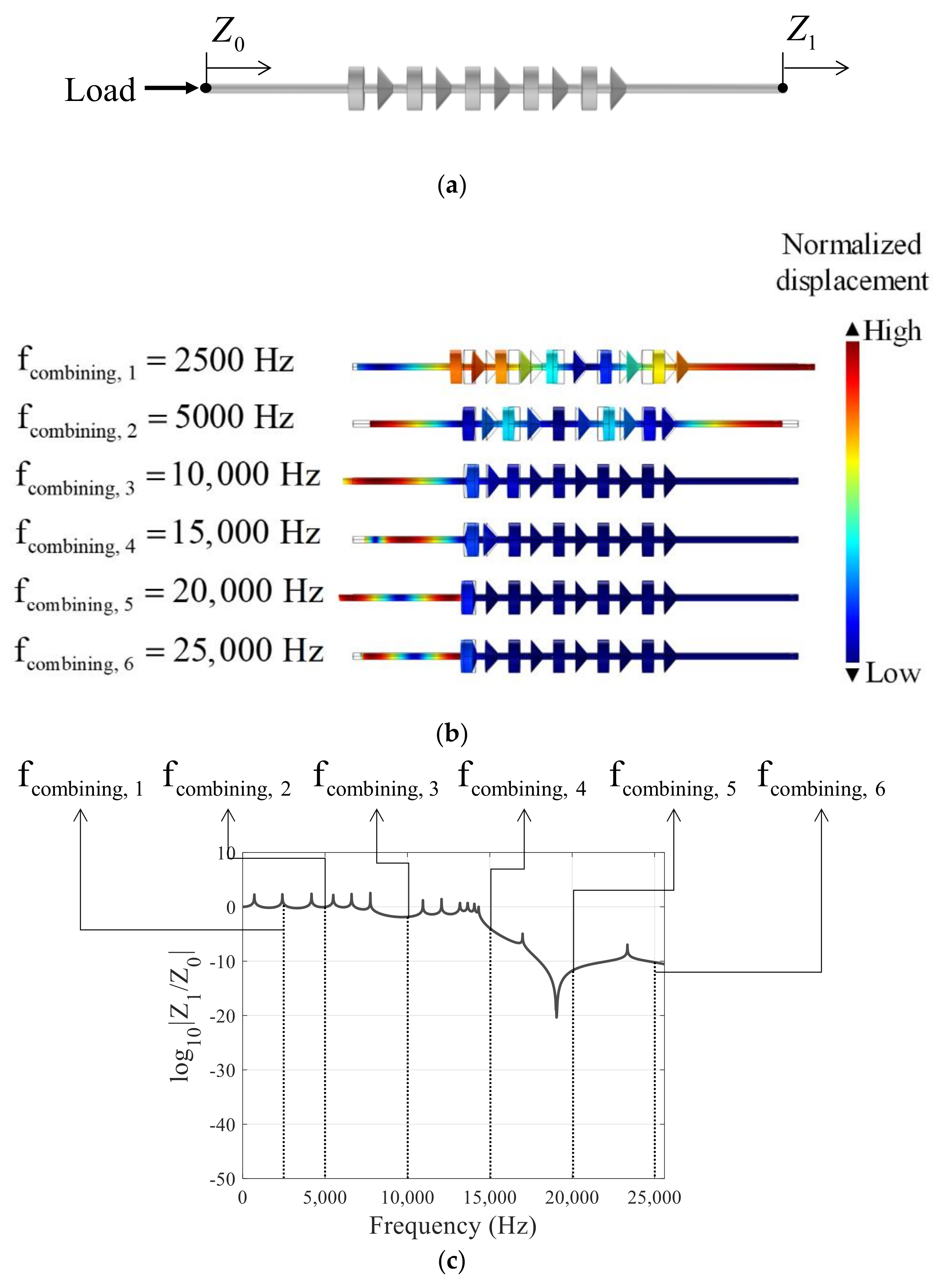
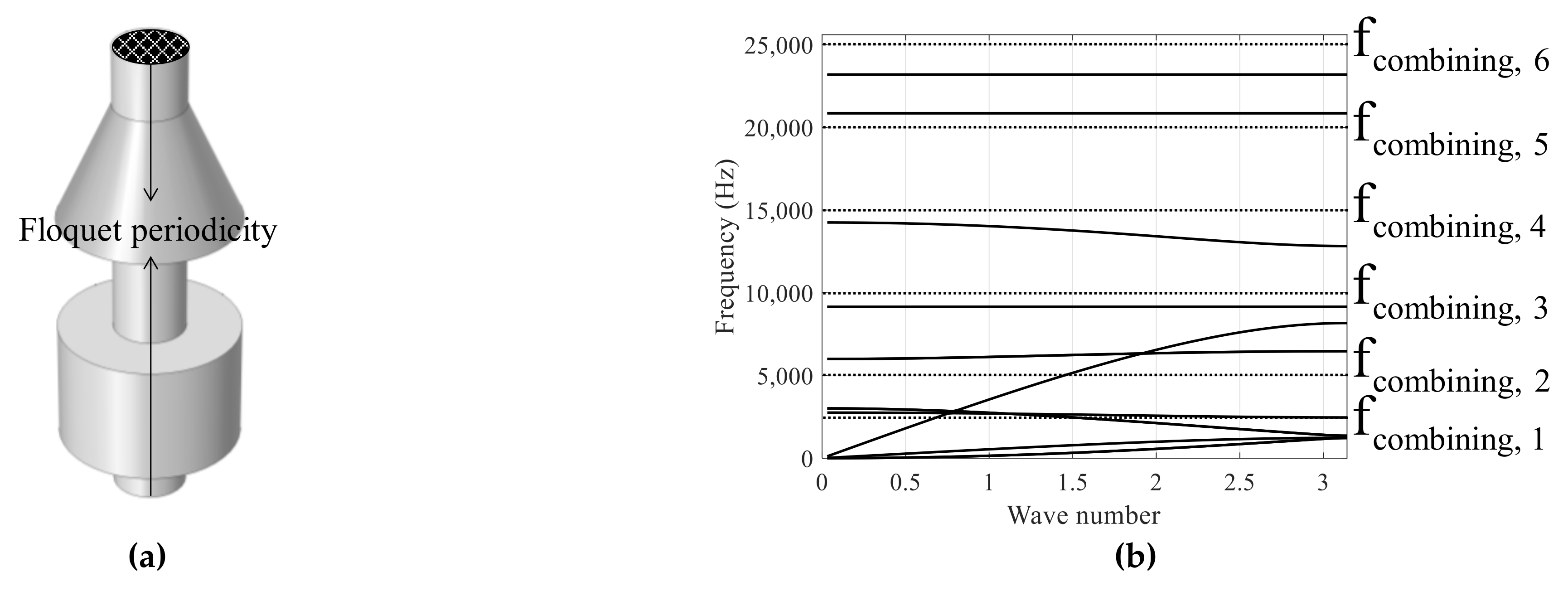
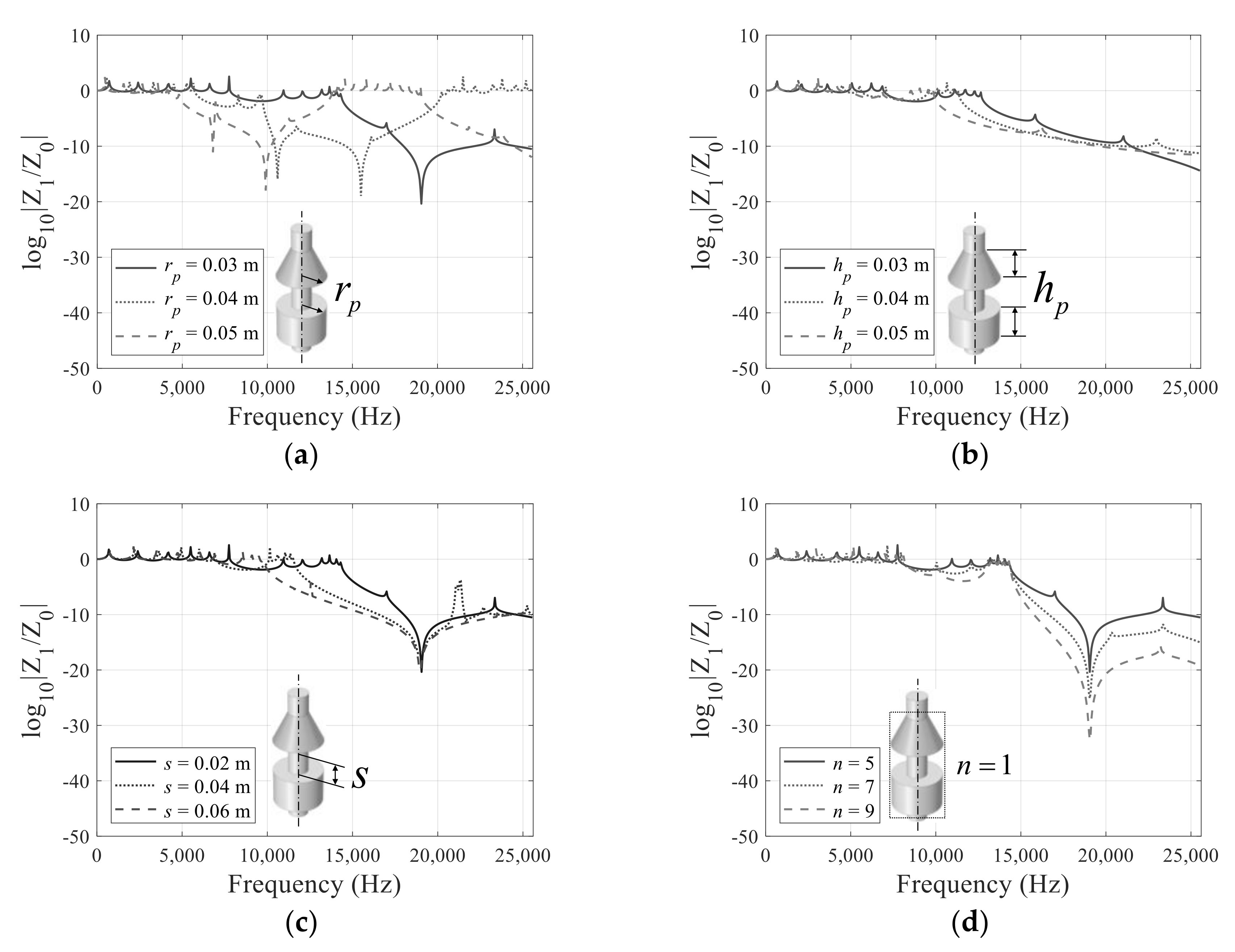
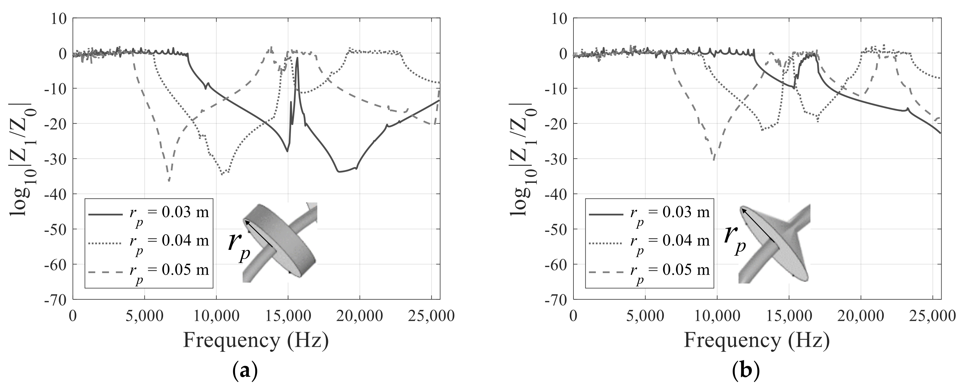
To show the characteristics of the band gap of the cylinder shape metamaterials, the cylindrical metamaterials made of aluminum are simulated by changing their dimensions. Although straight bar can be useful in supporting structure, the transmission vibrations need to be reduced. Therefore, the present metamaterials can be employed. In Figure 4, Figure 5 and Figure 6, the characteristics of the present metamaterials are investigated. The boundary conditions applied to the interpretation are shown in Figure 4a and the displacements at some frequencies are shown in Figure 4b. Figure 5 shows the dispersion relation of the unit cell which are then matched with the frequency responses in Figure 4c. Figure 6 shows the ratio of output acceleration (Z1) to input acceleration (Z0), with some different unit cells to investigate the effect of geometric variables in the radius (rp) of cylinder, the height (rh) of cylinder, the distance (s) between cylinder, and the number (n) of cylinders. As the metamaterials based on the resonances of the cylinder structures, the low-frequency band gaps of the cylindrical metamaterials can be observed by increasing the mass of the cylinder or by increasing the radius and the height of the unit structure. On the contrary, the high-frequency band gaps can be obtained by decreasing the length of the distance (s) in Figure 6c. Figure 6a shows the frequency response with the three different radii of the mass part. As expected, the starting frequency of the band gap becomes higher by decreasing the radius. With 0.03 m for the radius, the band gap occurs at around 8700 Hz. The frequency range of the band gap is observed from 6000 Hz to 19,000 Hz with 0.04 m for the radius, and from 4500 Hz to 13,500 Hz with 0.05 m for the radius. Figure 6b shows the frequency response functions with the different heights. With 0.03 m for the radius, the band gap is formed at 9700 Hz and it is increased to 8500 Hz and 7700 Hz with 0.04 m and 0.05 m as their respective radii. Compared with the effect of the radius, the effect of the height of the cylinder is relatively small. As the longitudinal stiffness is inversely proportional to the length of the beam, the range of the band gap frequency becomes lower with a longer length(s) in Figure 6c. This is partially due to the mass effects of the cylinder. The band gap appears at about 7600 Hz and 8800 Hz with 0.06 m and 0.04 m for the distances, respectively. It is also observed that the band gap becomes wider. The above studies show that, by controlling the geometries, the frequency range of the band gap can be controlled. The periodic rod structures can be applied for various engineering applications. For example, a rod structure can stop oscillating in a specific frequency region. Therefore, it can be applied to create a kind of supporting structure for vibrating buildings.

Figure 4.
(a) Cylindrical metamaterials, (b) the displacement at certain and (c) the frequency responses (.
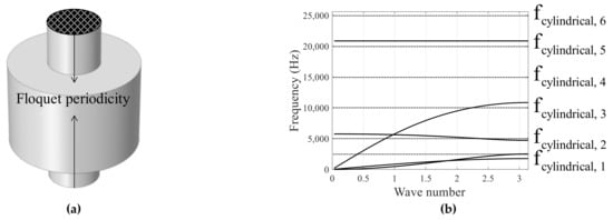
Figure 5.
(a) Floquet periodic condition of unit cell and (b) the dispersion relation for the unit cell in cylindrical metamaterials ().
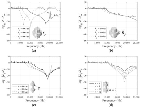
Figure 6.
Frequency response analysis results for each parameter of straight beam with repeated cylinders of the metamaterials for the longitudinal wave: (a) (b) (c) (d) .
3.2. Straight Beam with Conical Metamaterials
For the second example, the conical metamaterials are simulated in Figure 7a. The frequency responses in Figure 7b are matched with the dispersion relationship in Figure 8. Similar to the cylindrical unit cell, the changes of the effective mass and stiffness make the shifts of the band gap. It is interesting that the radius of the cone has a large effect on the band gap. By increasing 0.01 m, the frequency range of band gap is shifted at about 2000 Hz. The height of the cone, the distance between the cone, and the number of the unit cells have little effect.
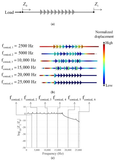
Figure 7.
(a) Model of conical metamaterials, (b) displacement at certain frequency and (c) the frequency responses ().
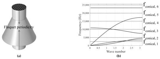
Figure 8.
(a) Floquet periodic condition of unit cell and (b) dispersion relation for a unit cell in conical metamaterials ().
The frequency response is shown in Figure 9. With 0.03 m for the radius of cone, the band gap can occur at 17,300 Hz. With 0.04 m, the band gap about 11,300 Hz to 21,000 Hz is observed. By increasing the radius, the band gap becomes lower in Figure 9a. The height of the cone has influence too; the band gap at 15,000 Hz with 0.03 m, 13,000 Hz with 0.04 m, and 11,400 Hz with 0.05 m. The effect of the distance is similar to that of the cylindrical metamaterials. By increasing the number of the unit cells, the depth of the band gap becomes lower. In conclusion, the simulations show that the frequency ranges of the band gap are different, but the geometric parameters have the similar effects.
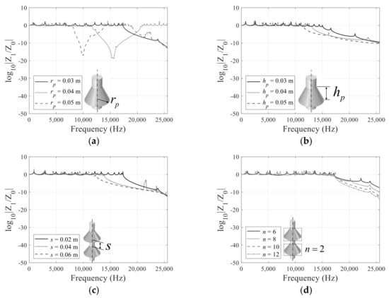
Figure 9.
Frequency response analysis results for each parameter of straight beam with repeated conical of the metamaterials for the longitudinal wave: (a) (b) (c) (d) .
3.3. Straight Beam with Cylindrical and Conical Metamaterials
In this subsection, the combination of the cylindrical and the conical metamaterials is considered. Figure 10 and Figure 11 show the frequency response functions and the dispersion relation of the combined metamaterials. By combining the two hetero-metamaterials, the frequency ranges of the band gaps are observed between the frequency ranges of the cylindrical structures and the conical structures. The studies imply that the combinations of different unit cells can be used for the wave attenuation of the longitudinal stress wave.
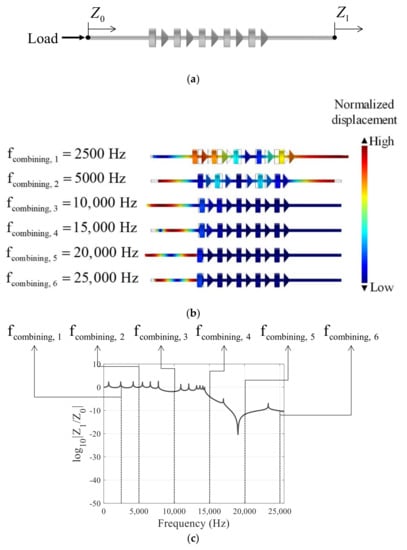
Figure 10.
(a) Model of combining cylindrical and conical metamaterials, (b) the displacement at certain frequency and (c) the frequency responses ().

Figure 11.
(a) Floquet periodic condition of unit cell and (b) dispersion relation for a unit cell in combining cylindrical and conical metamaterials (.
Figure 12 shows the frequency response of the cylindrical and the combined conical structures. The analysis about four parameters are performed. The results of the change in the radius of the two shapes are shown in the Figure 12a. As the radius increases, the band gap occurs in the lower frequency range. With 0.03 m for the radius, the band gap occurs at around 8700 Hz. The frequency range of the band gap is observed from 6000 Hz to 19,000 Hz with 0.04 m for the radius, and from 4500 Hz to 13,500 Hz with 0.05 m for the radius. With the 0.03 for the radius of two shapes, the band gap occurs at about 14,000 Hz or more. The frequency range of the band gap is observed at 8300~20,000 Hz with 0.04 m for the radius, and at 4800~14,000 Hz with 0.05 m for the radius. It can be seen that this frequency range corresponds to the intermediate level of the radius in the cylindrical and the conical structures. With 0.03 m for the radius of the cylinder, the band gap is 8700 Hz or more, and with 0.03 m for the radius of the cone, the band gap observed 17,300 Hz or more. When using combined structures, the band gap occurs at 14,000 Hz or more. Figure 12b shows the frequency response functions with the different heights of the combined metamaterials. With 0.03 m for the heights of the cylinder and the cone, the band gap is formed at 12,600 Hz or more. The frequency range of the band gap is observed at 11,300 Hz or more with 0.04 m for the height, and at 12,600 Hz or more with 0.05 m for the height of combined metamaterials. Compared with the effect of the radius, the effect of the heights is relatively small. This result also corresponds to the middle level using the cylindrical and the conical structures, respectively. The effect of the distance between the cylinder and the cone is shown in Figure 12c. It is similar to that of the cylindrical and the conical metamaterials, except the frequency range of band gap that occurs in the cylindrical and conical structures. Figure 12d shows the influence of increasing the number of the unit cells, which lowers the depth of the band gap. In conclusion, the numerical analysis shows the same tendency of the cylindrical and conical metamaterials. As a result of combining the cylindrical and the conical metamaterials analysis, it can be established that the band gap occurs at the intermediate level frequency range when the cylinder and the cone structures are using, respectively.
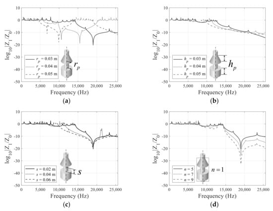
Figure 12.
Frequency response analysis results for each parameter of straight bar with repeated cylinder and conical of the metamaterials for the longitudinal wave: (a) (b) (c) (d) .
3.4. Curved Beam with Metamaterials
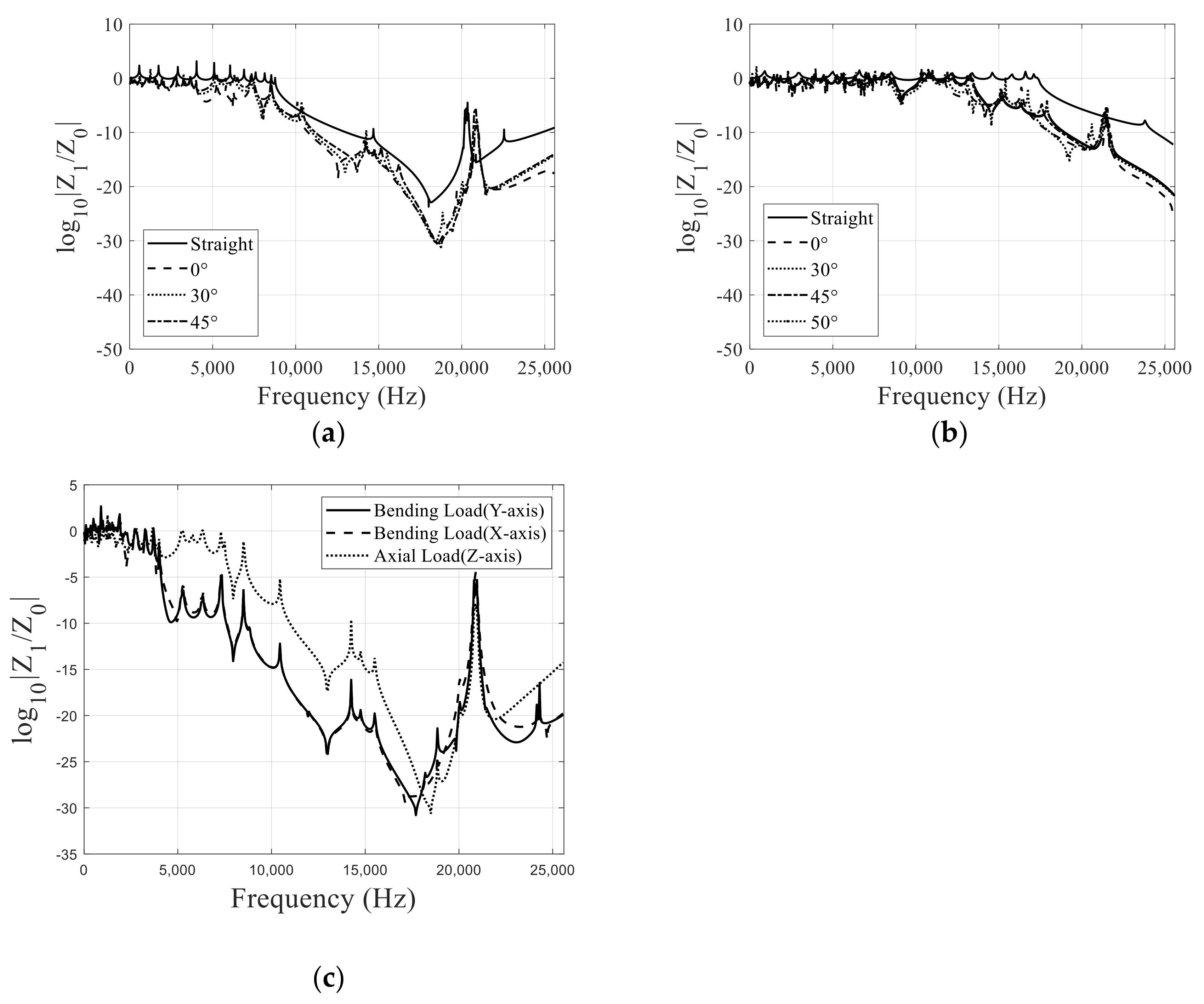
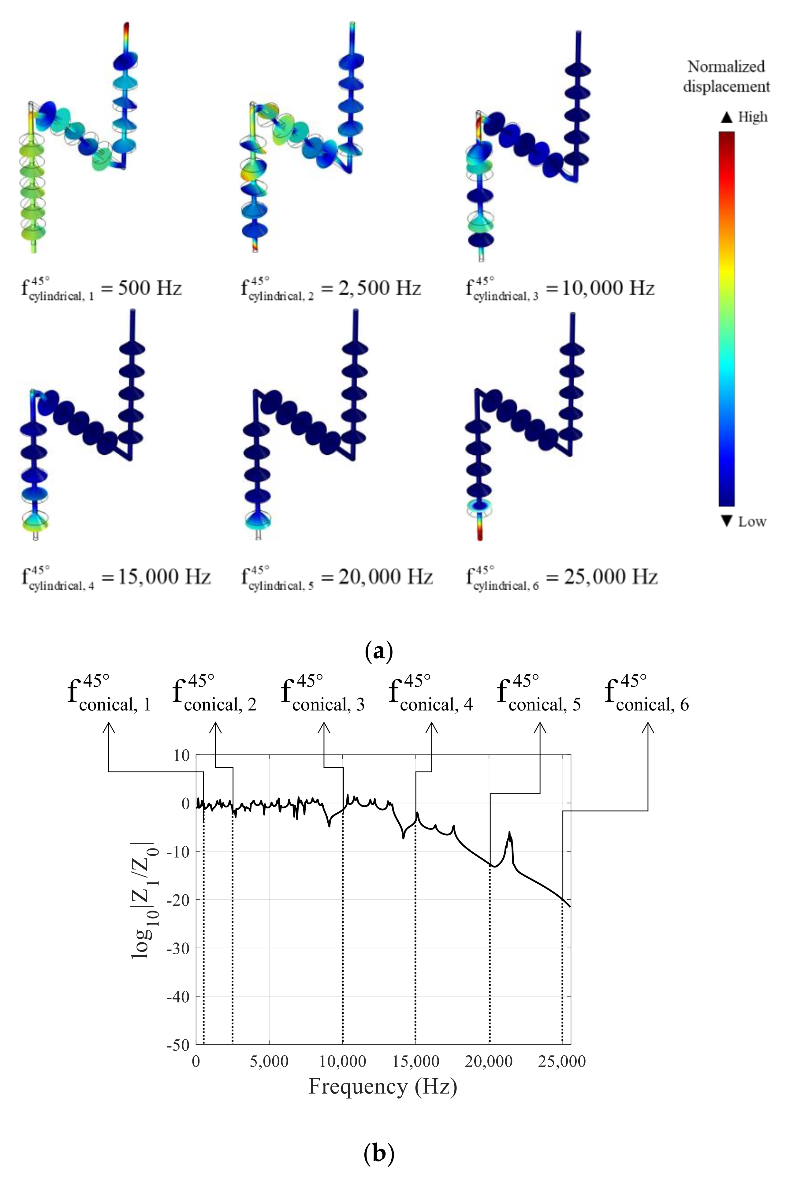
For the third example, the curved beams with the cylindrical and the conical metamaterials are considered in Figure 13. Metamaterials with periodic rod structures can be applied in a variety of engineering applications. For example, periodic rod-shaped metamaterials can stop vibrations in a specific frequency range, so they can be installed as supporting structures that prevent the transmission of vibrations and noise. However, in some cases, straight metamaterials are often not suitable for installation in tight spaces. To overcome this, it is sometimes necessary to install a curved metamaterial. Note that the cylindrical metamaterials may have some issues in installation at junctions. Thus, the conical metamaterials can be a solution as it allows some geometrical gaps among the metamaterials than the cylindrical metamaterials. To test this characteristic, Figure 13 shows the simulations of the bend bars with the cylindrical and the conical metamaterials. To our best knowledge, some relevant researches that consider wave transmission with metamaterials only investigate waves in straight bar as well as the wave transmission at curved structures and the bandgap phenomenon with the cylindrical and the curved conical metamaterials. Figure 14 shows the simulation results with the bar bended by certain angles with the metamaterials and compares the wave transmissions. The frequency response results for the curved bar with the cylindrical metamaterials are shown in Figure 14a. The frequency responses at 0°, 30°, 45°, and straight bar show that the bandgaps appear at around 8700 Hz with these simulation conditions. The frequency responses with the conical metamaterials are drawn in Figure 14b. As it allows some geometrical gaps among the unit cells, it is possible to install the metamaterials with a large bended angle, i.e., 50°. The band gaps occur at around 17,000 Hz in the straight bar with the conical metamaterials, and the band gaps appear at around 13,000 Hz the curved bar. Figure 15a shows the displacements at certain frequencies. One of the benefits of the metamaterials in the curved structure lies in the fact that it shows the bandgaps in x and y directions. In other words, as the bending loads in x and y directions become the axial loads at the curved section of the structure, the bending loads can be stopped with the present structure. For an example, Figure 14c shows the bandgaps of the curved cylindrical metamaterials (θ = 30°) with respect to the bending loads in x and y directions. As illustrated, due to the curved structure, it is possible to exploit the bandgaps for the bending loads. Figure 16 shows some mechanical deformations at some frequencies.
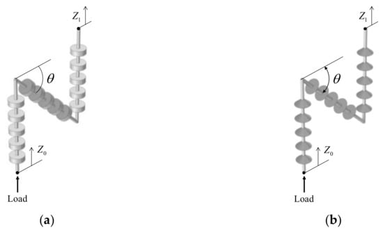
Figure 13.
Model of (a) the curved cylindrical metamaterials and (b) the curved conical metamaterials.
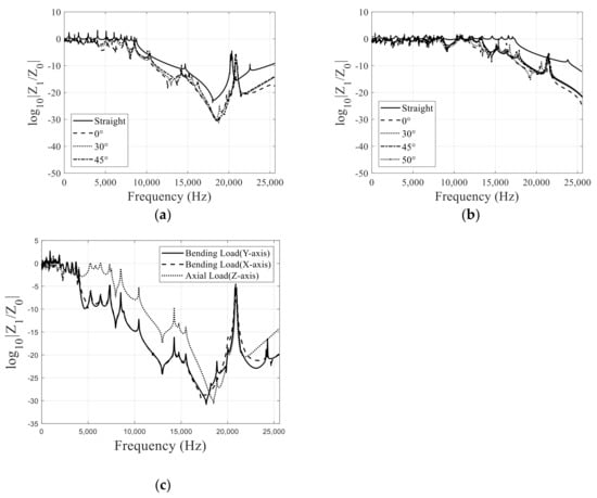
Figure 14.
Frequency responses of (a) the curved cylindrical metamaterials, (b) the curved conical metamaterials and (c) the frequency responses for the bending loads in x and y directions (θ = 30°).
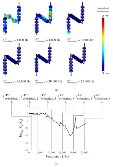
Figure 15.
(a) Displacement at certain frequency of the cylindrical metamaterials, (b) the frequency responses (θ = 45°).

Figure 16.
(a) Displacement at certain frequency of the conical metamaterials and (b) the frequency responses (θ = 30°).
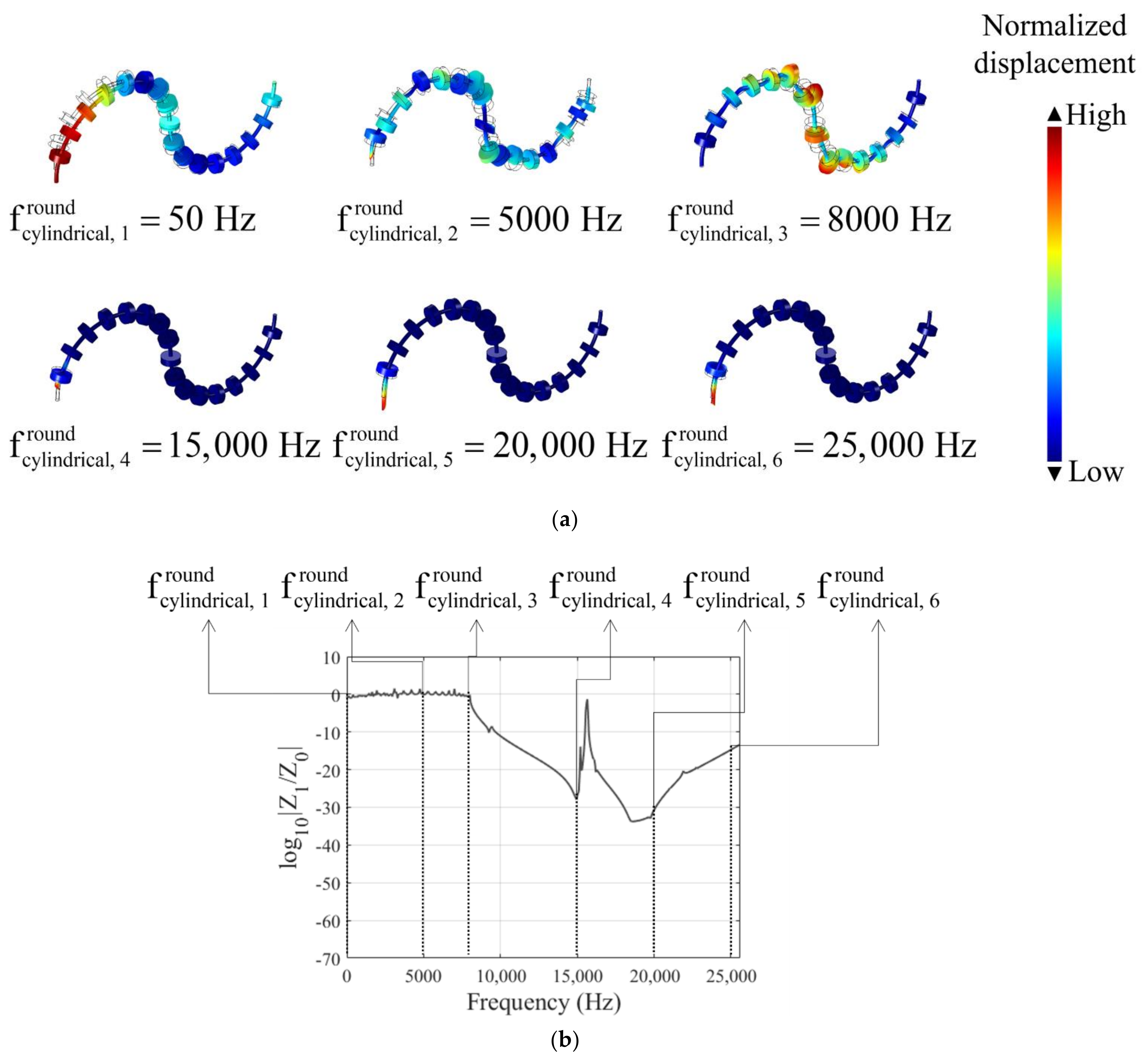
Figure 17 shows examples of the curved bars with the cylindrical, while the conical metamaterials and their frequency responses are shown in Figure 18. With 0.03 m for the radius (rp), the bandgaps appear between 8000 Hz to 15,000 Hz, and at around 16,000 Hz. By increasing the radius, the bandgap becomes lower. The same tendency can be observed in the case of the conical metamaterials in Figure 18b. Some wave propagations are shown in Figure 19 and Figure 20.

Figure 17.
Model of (a) the round cylindrical metamaterial and (b) the round conical metamaterial.
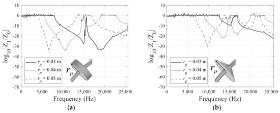
Figure 18.
Frequency response results of (a) the round cylindrical metamaterials and (b) the round conical metamaterials.
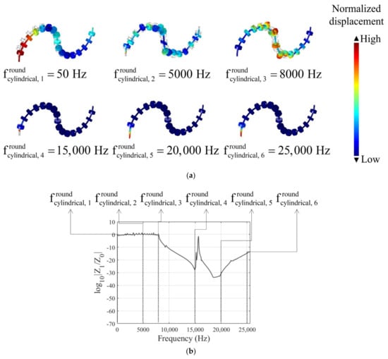
Figure 19.
(a) Displacement at a specific frequency of the round cylindrical metamaterials and (b) the frequency responses ().
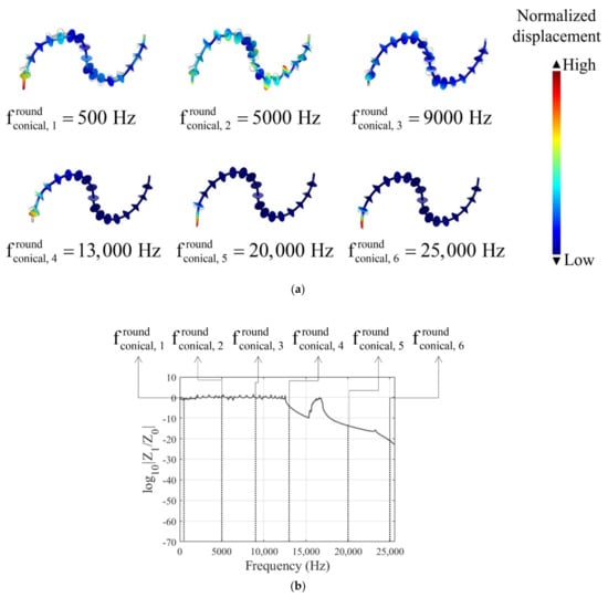
Figure 20.
(a) Displacement at a specific frequency of the round conical metamaterials and (b) the frequency responses (.
3.5. Experiments
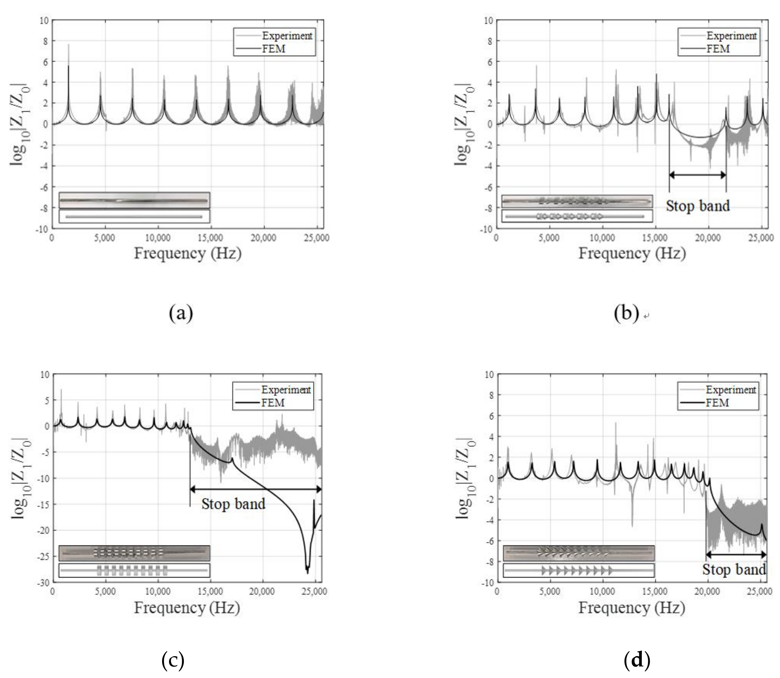
To validate the above analysis results by experiment, the experimental setup in Figure 21 is constructed. The beams are hindered by a string to apply the free boundary condition. Two accelerometers (PCB Piezotronics, Model 352C33) are attached to the beam to measure the longitudinal wave generated by the impact hammer (PCB Piezotronics, Model 086C03). The impact load of the impact hammer excites the structure and the entire frequency range are excited. Two accelerometers were used to measure the acceleration of input and output of structure. The signal from the accelerometers are measured by DAQ (National Instruments, Model NI-9234), and the ratio of output to input is recorded on PC. Figure 22a shows the straight beam without any other additional shape with 800 mm for height and 6 mm for radius, as well as its band gap by the finite element analysis and the experiment. As illustrated, the results of the experiment and the finite element analysis are matched to each other.
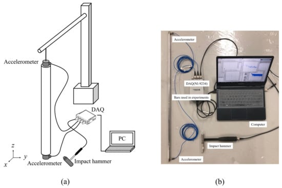
Figure 21.
Experimental setup (a) the schematic diagram and (b) the photograph of the experimental setup.
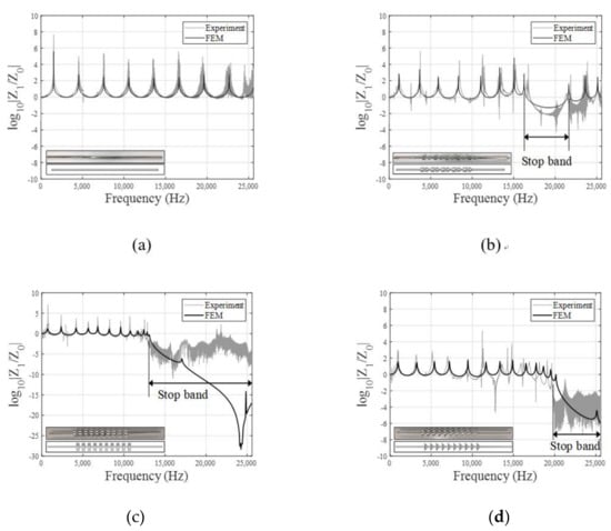
Figure 22.
Experiment and analysis results of (a) general bar without any other additional shape, (b) bar that includes cylinder and conical shape, (c) bar that includes cylinder shape and (d) bar that includes cone shape.
The results of combining the cylindrical and the conical metamaterials are shown in Figure 22b. The finite element analysis and the experiment results are matched together. The band gap appears from about 16,000 Hz to 22,000 Hz. Figure 22c shows the results of the cylindrical metamaterials. The band gap occurs at more than 12,850 Hz. In Figure 22c, the resonant frequencies of the experiment and the finite element simulation are matched to each other. The discrepancy exists after 15,000 Hz because the response is small enough and the response is displayed on a logarithmic scale. The results are also matched. In the case of the experiment, although noise is generated, frequency response falls to 0 or less in the section of band gap. The conical metamaterials analysis and experimental results are shown in Figure 22d. Analysis of the experiment shows the same result, i.e., that the band gap is displayed at over 19,600 Hz.
4. Conclusions
The longitudinal wave propagation of the mechanical metamaterial is theoretically and experimentally studied. We have demonstrated the possibility of using cylinder and conical structures, and how combining these two shapes controls wave motion in periodic structures. For a periodically repeating unit, cylindrical and conical structures are exploited for longitudinal wave in the straight rod and the curved rod. As well as a straight bar with a periodic structure, analysis of the curved bar was also conducted. The unit of various shapes can adjust the impedance mismatch of the structure, thereby controlling longitudinal waves. Finite element modeling was used to predict the dynamic behavior due to the impact load of straight bar in the periodic structure of cylinder and conical shape and the structure where these two shapes are combined. These analysis and predictions are confirmed by the results of relatively simple experiments due to processing problems. Unlike the common bar where the wave has not passed band gap, experimental and theoretical results indicate that cylindrical and conical periodic structures generate a band gap. It is possible to increase the number of band gaps and move the main frequency band through utilization of the radius, height, distance, and number of each shape. As a result, it is possible to control an unnecessary frequency during wave propagation through the periodic structure, considering a specific shape and each parameter as tools for establishing a band gap. This demonstrates the performance of straight and curved structures with periodic structures of conical and cylinder shape, which suppresses the propagation of waves, without the need for external energy supply to drive active devices such as electronic devices. One of the most interesting features of the metamaterials in curved structure is that the bandgaps for the loads in the other directions except the axial direction also can be exploited. We can use this phenomenon to set the band gap of the desired frequency band, and can consider the part for practical use. It is expected that there will be various fields of application, such as that it can be applied not only to straight structures but also to curved structures, and this part will be explored through future research. In addition, the metamaterial structure for bending load should be researched in the future.
Author Contributions
Conceptualization, G.H.Y.; methodology, D.H.O.; validation, D.H.O. and G.H.Y.; data curation, D.H.O.; writing—original draft preparation, D.H.O.; writing—review and editing, G.H.Y.; visualization, D.H.O.; supervision, G.H.Y.; project administration, G.H.Y.; funding acquisition, G.H.Y. All authors have read and agreed to the published version of the manuscript.
Funding
This work was supported by Korea Institute of Energy Technology Evaluation and Planning (KETEP) grant funded by the Korea government (MOTIE) (20202020800030, Development of Smart Hybrid Envelope Systems for Zero Energy Buildings through Holistic Performance Test and Evaluation Methods and Fields Verifications).
Conflicts of Interest
The authors declare no conflict of interest.
References
- Brillouin, L. Wave Propagation in Periodic Structures: Electric Filters and Crystal Lattices; Courier Corporation: North Chelmsford, MA, USA, 2003. [Google Scholar]
- Kronig, R.D.L.; Penney, W.G. Quantum mechanics of electrons in crystal lattices. Proc. R. Soc. Lond. Ser. A Contain. Pap. A Math. Phys. Character 1931, 130, 499–513. [Google Scholar]
- Sigalas, M.M.; Economou, E.N. Elastic and acoustic wave band structure. J. Sound Vib. 1992, 158, 377–382. [Google Scholar] [CrossRef]
- Griffiths, D.J.; Steinke, C.A. Waves in locally periodic media. Am. J. Phys. 2001, 69, 137–154. [Google Scholar] [CrossRef] [Green Version]
- Martinsson, P.; Movchan, A. Vibrations of lattice structures and phononic band gaps. Q. J. Mech. Appl. Math. 2003, 56, 45–64. [Google Scholar] [CrossRef]
- Mead, D. Wave propagation and natural modes in periodic systems: I. Mono-coupled systems. J. Sound Vib. 1975, 40, 1–18. [Google Scholar] [CrossRef]
- Mead, D. A general theory of harmonic wave propagation in linear periodic systems with multiple coupling. J. Sound Vib. 1973, 27, 235–260. [Google Scholar] [CrossRef]
- Leung, A.-T. Dynamic analysis of periodic structures. J. Sound Vib. 1980, 72, 451–467. [Google Scholar] [CrossRef]
- Faulkner, M.; Hong, D. Free vibrations of a mono-coupled periodic system. J. Sound Vib. 1985, 99, 29–42. [Google Scholar] [CrossRef]
- Zhong, W.; Williams, F. On the direct solution of wave propagation for repetitive structures. J. Sound Vib. 1995, 181, 485–501. [Google Scholar] [CrossRef]
- Hinke, L.; Mace, B.; Brennan, M. Finite Element Analysis of Waveguides; ISVR Technical Memorandum No 932, Southempton, UK. 2004. Available online: https://eprints.soton.ac.uk/28129/1/Pub3838.pdf (accessed on 6 August 2021).
- Mead, D. Wave propagation in continuous periodic structures: Research contributions from Southampton, 1964–1995. J. Sound Vib. 1996, 190, 495–524. [Google Scholar] [CrossRef]
- Orris, R.M.; Petyt, M. A finite element study of harmonic wave propagation in periodic structures. J. Sound Vib. 1974, 33, 223–236. [Google Scholar] [CrossRef]
- Jensen, J.S. Phononic band gaps and vibrations in one-and two-dimensional mass-spring structures. J. Sound Vib. 2003, 266, 1053–1078. [Google Scholar] [CrossRef]
- Kittel, C.; McEuen, P. Introduction to Solid State Physics; Wiley: New York, NY, USA, 1976; Volume 8. [Google Scholar]
- Bondarenko, A. Elastic waves in rods of rectangular cross section. In European Women in Mathematics; World Scientific: London, UK, 2010; pp. 103–111. [Google Scholar]
- Kalkowski, M.K.; Muggleton, J.M.; Rustighi, E. Wave propagation in rods with an exponentially varying cross-section—modelling and experiments. Journal of Physics: Conference Series. In Proceedings of the 13th International Conference on Motion and Vibration Control (MOVIC 2016) and the 12th International Conference on Recent Advances in Structural Dynamics (RASD 2016), Southampton, UK, 4–6 July 2016; Volume 744, p. 012036. [Google Scholar]
- Tongele, T.; Chen, T. Control of longitudinal wave propagation in conical periodic structures. Modal Anal. 2004, 10, 1795–1811. [Google Scholar] [CrossRef]
- Graff, K.F. Wave Motion in Elastic Solids; Courier Corporation: North Chelmsford, MA, USA, 2012. [Google Scholar]
- Gupta, R.B. Propagation of Elastic Waves in Rods With Variable Cross Section. J. Appl. Mech. 1979, 46, 951. [Google Scholar] [CrossRef]
- Ruzzene, M.; Baz, A. Active control of wave propagation in periodic fluid-loaded shells. Smart Mater. Struct. 2001, 10, 893. [Google Scholar] [CrossRef]
- Chen, T.; Ruzzene, M.; Baz, A. Control of wave propagation in composite rods using shape memory inserts: Theory and experiments. J. Vib. Control 2000, 6, 1065–1081. [Google Scholar] [CrossRef]
- Chiang, W.F.; Lin, S.X.; Lee, Y.X.; Shih, Y.H.; Liu, J.H.; Silalahi, H.M.; Lee, C.R.; Huang, C.Y. Passively Tunable Terahertz Filters Using Liquid Crystal Cells Coated with Metamaterials. Coatings 2021, 11, 381. [Google Scholar] [CrossRef]
- Chiang, W.F.; Lin, S.X.; Lee, Y.X.; Shih, Y.H.; Liu, J.H.; Silalahi, H.M.; Lee, C.R.; Huang, C.Y. Effect of Thicknesses of Liquid Crystal Layers on Shift of Resonance Frequencies of Metamaterials. Coatings 2021, 11, 578. [Google Scholar] [CrossRef]


Publisher’s Note: MDPI stays neutral with regard to jurisdictional claims in published maps and institutional affiliations. |
© 2021 by the authors. Licensee MDPI, Basel, Switzerland. This article is an open access article distributed under the terms and conditions of the Creative Commons Attribution (CC BY) license (https://creativecommons.org/licenses/by/4.0/).