Abstract
Current efforts are focused on assembling new constructions while applying non-conventional actuators, for example, artificial pneumatic muscles, in engineering manufacturing processes. The reason is to eliminate stiffness and inflexibility of equipment structures that make sharing the working space of the technological equipment complicated. This article presents the results of experimental measurements of pressures in artificial muscles and rotations of the actuator with artificial muscles at various loads, using a testing device of an antagonistic actuator. The measurement results were used to create the function of the course of the static property of the antagonistic actuator with artificial muscles of the Festo type and to determine a mathematical model of the actuator dynamics, while applying the method of least squares.
1. Introduction
In the recent past, a rather fast growth of automated and robotised technological workplaces has been observed in various industries, including the logistics processes which have been, until now, avoided by automation and robotisation [1]. Paper [2] deals with the results of the application of a speed signal averaging device and the acceleration loop. This device is applied in electric servo systems as well as electric servo systems of industrial robots. By applying this circuit, the robot positioning uncertainty was reduced by as much as 47% [2]. Manipulation equipment used in automated technological processes is rather accurate and efficient. Its disadvantage is a heavy weight and stiff and inflexible structure. Such drawbacks may be partially solved by applying pneumatic artificial muscles (PAMs) [3]. Pneumatic artificial muscles are referred to in the literature by different terms, such as Air Muscle, Fluidic Muscle, Pneumatic Muscle Actuator, Fluid Actuator, Fluid-Driven Tension Actuator, Axially Contractible Actuator, Tension Actuator, and Braided Pneumatic Muscle Actuator [4,5,6], whereas, from a structural point of view, in most cases it is in principle the McKibben’s pneumatic artificial muscle. As for its structure, it is a rather simple device consisting, in its basic form, of the internal layer, external layer, and end pieces [7]. Generally, it is a braided artificial muscle. Its behaviour depends on its shape, contraction, and force when pressurised. These muscles are usually of a cylindrical shape [8]. In addition to significant hysteresis of properties and insensitivity, the conventional McKibben’s pneumatic artificial muscle has also a short service life.
In an effort to eliminate these drawbacks, several improvements have been suggested to substantially increase the applicability of PAMs as actuators in the field of industrial robotics. J. M. Winters [9] published a muscle with external braiding. It differs from the McKibben’s muscle in the internal layer structure. The main advantage of this muscle is the simplicity of assembly. J. M. Yarlott has patented the mesh artificial muscle [10]. It consists of an elastomer tube and a series of fibres stretched axially to both muscle ends that transform the pressure energy into the tensile energy. Unlike braided muscles, meshed artificial muscles are of lower density of the mesh surrounding the membrane. The mesh has larger openings and is more adjoined to the membrane. Meshed muscles can thus only stand lower pressures. M. Kukolj [11] has patented the artificial muscle. As compared to the McKibben’s muscle, it has a different external layer. McKibben’s muscle has a thick membrane braid, while Kukolj uses open openings, whereas the fibres are at certain spots firmly connected together and form a mesh. In the non-pressurised state, the openings are visible, but after the pressurisation, the openings disappear because all the layers will adjoin to each other. The problem of friction between the elastic layer and the braid is solved by lubrication. The reason for creating such muscle was the finding that a thick mesh tends to constrict faster than the membrane. G. Immeg and M. Kukolj [12] have patented a robotically active component based on an artificial muscle (Robotic Muscle Actuator). It is not reminiscent of any of the previous muscles. It is made of non-elastic material consisting of plenty of juts. The muscle coating is characterised with high tensile stiffness and flexibility. Friction is minimal and, therefore, it can develop a greater force. Such force approaches to the maximum theoretical value; it excels in high relative shortening and minimum hysteresis.
A disadvantage of the conventional structure of the McKibben’s pneumatic artificial muscle is the formation of rather high friction between the fibres in the external layer and the rubber wall of the tube in the internal layer. Such friction reduces the force developed by the muscle and is also manifested as hysteresis that complicates the muscle control. This type of muscle is typical for threshold insensitivity when the pressure increases. Muscle contraction occurs only after a certain level of pressure increase is achieved [13,14]. The elimination of such friction and thus also of hysteresis will facilitate the muscle control by reducing its threshold insensitivity. It was achieved by constructing a membrane with longitudinal grooves. The grooves are free to broaden due to radial pressure when the muscle is being filled. Tensile forces are transmitted through extremely strong polymer fibres located in every groove of the membrane [15,16,17]. Such pneumatic artificial muscle was named the Pleated Pneumatic Artificial Muscles—PPAM. Increasing the service life by eliminating the effect of dry friction between the tube and the fibres, as well as between the fibres themselves, represents the connection of the elastic tube and glass fibres into a single unit. This facilitates a much smaller width of hysteresis and a narrower insensitivity zone [18]. This principle is applied in MAS–20 pneumatic artificial muscles that appear to be very appropriate for applications in industry due to their robust structure. Properties, shapes, and behaviour of pneumatic artificial muscles are comparable to human muscles; this makes them easy to combine into more complex manipulation mechanisms. Other important properties of pneumatic artificial muscles are listed in papers [19,20] and their basic drawbacks are described by Mižáková [21] and Wickramatunge et al. [22] The basic principle of their action is presented by Trojanova and Čakurda [23], Hošovský et al. [24], Tóthová and Piteľ [25], and Sárosi et al. [26].
Behind the effective movement of the robot or manipulator are many aspects that have to be mastered in motion control. Modelling of kinematics and dynamics of manipulators plays an important role in the control accuracy of these devices. Trojanova et al. in [27] describe the dynamics of a manipulator with two degrees of freedom, while the dynamic model of the manipulator’s arm is derived using Lagrangian formalism, which considers the difference between the kinetic and potential energy of the system. In [28], Nezhad and Korayem described the dynamic and kinematic model of industrial manipulator Hyundai HS165. The kinematic model is obtained using the D-H parameters. The obtained model is compared to the simulations and the experimental test. The difference between the computed and real load is slight, which indicates that the dynamic model is quite accurate. Ref. [29] describes the kinematic model of a five-DOF spatial manipulator used in robot-assisted surgery. In [30], the dynamic model of a robotic manipulator is described using the Euler–Lagrange formulation. Sung et al. [31] derived the exact solution of kinematics, and they provide geometry intuition and meaning of kinematics equations.
The manuscript deals with improvement of the layer coating technology of painting robots, resulting in the formation of a new painting robot concept. Requirements for painting robots with low energy demands lead ultimately to a solution of a light robotic arm driven by pneumatic artificial muscles in an antagonistic configuration (pneumatic actuator). Its application in robotics is directly dependent on the perfection of a computerized control system. Designed original control was carried out on the real system through a PC using the software Matlab/Simulink. The concept of the control system ensures maximum stiffness of actuator mechanism.
2. Materials and Methods
2.1. Problem Formulation
Engaging pneumatic artificial muscles in antagonistic connection facilitates the regulation of their own stiffness/compliance, which is not usual in conventional types of actuators. The primary problem is complicated modelling and control while using pneumatic artificial muscles. Complicated modelling and control are caused by non-linear muscle properties, medium compressibility, and friction of the internal structure. Modelling and simulation of actuators based on pneumatic artificial muscles require the knowledge of the mathematical relationship between the muscle strength and its contraction at various pressures in the muscle. For this purpose, we carried out the measurements of static properties of the MAS–20 pneumatic artificial muscle used in experiments [32].
2.2. Experimental Material
Experimental research was focused on MAS–20 pneumatic artificial muscles (PAM) with a robust structure The internal layer of this type of PAM consists of a rubber tube and the external layer is formed by fibres. The layers are interconnected to minimise the friction between the fibres and the tube that causes hysteresis (Figure 1). Materials typically used for the manufacture thereof are chloroprene and aramid.
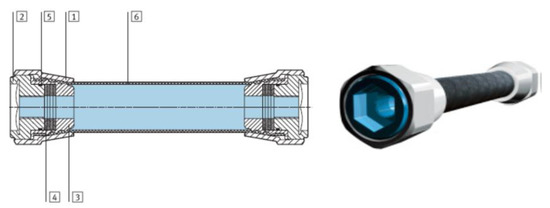
Figure 1.
Pneumatic artificial muscle of MAS–20 type (1) connecting matrices (wrought aluminium alloy); (2) flange (wrought aluminium alloy); (3) internal cone (wrought aluminium alloy); (4) disc springs (steel); (5) sealing ring (nitrile rubber); (6) tube (chloroprene and aramid) [33].
The elastic tube and the glass fibres of MAS–20 are connected into a single unit. This facilitates a much smaller width of hysteresis and a narrower insensitivity zone. MAS–20 artificial muscles were chosen as the research object because in terms of their application in industry, they appear to be highly applicable due to their long service life, as compared to other types of PAM.
2.3. Testing Device
The testing device is the experimental actuator with pneumatic artificial muscles in antagonistic connection. The actuator with PAMs in antagonistic connection (Figure 2) consists of two artificial muscles interconnected with a roller chain. The chain transmits the forces from the muscles to the gear wheel that is firmly attached to the output shaft performing a rotary motion (not depicted). An experimental actuator based on PAM with one distance level (Figure 2) was designed at the Department of Industrial Engineering and Informatics, Faculty of Manufacturing Technologies with a Seat in Prešov, Technical University of Košice.
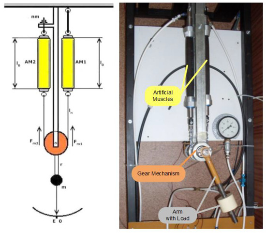
Figure 2.
Experimental actuator based on PAM—An antagonistic connection of pneumatic artificial muscle.
The actuator is a kinematic structure consisting of two antagonistic pneumatic artificial muscles (Figure 2), interconnected with a pull chain that carries the gear wheel mounted on and attached to the output revolving shaft. Rotation (position) of the shaft is proportional to the difference in pressures in individual muscles. The stiffness of the shaft’s position in the respective direction is determined by the magnitude of the pressure in the respective pneumatic muscle that is subjected to tension.
The experiments were carried out with the actuator comprising a pair of pneumatic artificial muscles of the MAS–20 type; their movement is transmitted through a pulley with a chain gear. An arm with a load is attached to the shaft. The active component consists of two pairs of directly controlled two-way electromagnetic valves, for each muscle 1 inlet and 1 outlet valve, MATRIX EMX 821.104C224. The arm’s position is measured by the IRC 120 incremental encoder with 2500 pulses/rev. The pressure in artificial muscles is sensed by pressure transducers PMD 60G with an analogue output signal of 0–10 V DC.
2.4. Experiment Methodology
The basic component of the control unit was a PC with an Intel Core 2 Quad processor with a clock frequency of 2.33 GHz and a 4 GB operating memory. The main component for interconnecting the real system with the computer was the input–output measuring card of the MF 624 type by Humusoft. It contains a 14-bit A/D converter with a simple shaper, 4 software-adjustable ranges, and an 8-channel multiplexer at the inlet, 8 independent 14-bit D/A converters with a double buffer, 8-bit numerical input and 8-bit numerical output, and 4 inputs for an incremental sensor (simple or differential). One of them is used in one mode. It is supplied with the Real Time Toolbox for Matlab. The card is intended for a PCI slot. Four bits of numerical output, compatible with TTL logic circuits, were used for the control. Analogue outputs use 4 voltage ranges (±10 V, ±5 V, 0–10 V, 0–5 V) selected by the software. A signal from the analogue output is normed into the range of ±1. The maximum sampling frequency determined by the used hardware was 500 Hz. Although this hardware facilitated increasing the sampling frequency, it would require using input blocks with the buffer. These are only applicable in the control because it is possible to use delayed processing of the obtained specimens by the software. With regard to the requirement of continuous control of the actuator, such blocks could not be used; nevertheless, the above-mentioned sampling frequency was sufficient. The control block also included a module with the EPAM (Electro-Pneumatic Action Module) working designation, facilitating adjustments of the control parameters from the measuring card output for the valve inputs (the voltage of the signal corresponding to the logic unit was 5 V, the control voltage of valves was 24 V). Within the implementation of automatic control using a computer, the interface with manual control was maintained; it proved to be very useful for adjusting the basic status of the actuator as well as fast verification of functionality. Schematic diagram of the experimental platform is depicted in Figure 3.
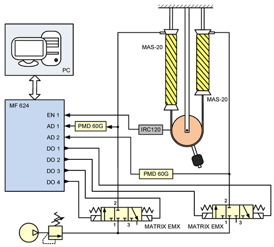
Figure 3.
Schematic diagram of the experimental platform.
3. Theory/Calculation
3.1. Physical Fundamentals
The principle of the action of such an actuator with artificial muscles (AMs) in antagonistic connection can be explained by Figure 4.
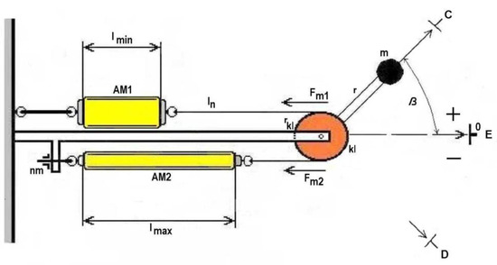
Figure 4.
Pneumatic artificial muscles in antagonistic connection.
If we have two identical muscles, AM1 and AM2, in antagonistic connection (Figure 2), and these muscles are filled with an identically large amount of compressed air, they shorten to the length l0, and the following applies [33]:
where:
lmax—maximum AM length,
Δl—change in AM length.
AM1 has the tensile force Fm1 which is transmitted through a pulley to the AM2 muscle that develops the tensile force Fm2. With identical filling pressures in AM1 and AM2, tensile forces become identical at identical values of their contractions and the actuator’s arm stabilises in the initial position. In such an initial position, the actuator stiffness is the highest if air pressure in both muscles is at its maximum.
At non-identical filling pressures in the muscles (Figure 4), the actuator’s arm stabilises in the position corresponding to the equality of tensile forces in both muscles. The angular displacement β for the arm exposed to the external load with the mass m depends on the pulley radius rkl for identical changes in the length of pneumatic artificial muscles. The rotation of the arm is subject to the equation:
If we designate the derivation of the muscle volume according to the length dV/dl generally as a non-linear function f, for the two muscles we can write the following:
where:
P1,P2—pressure in the respective muscle,
l10,l20—initial lengths of both muscles.
The above-mentioned equation (3) indicates that the length of each muscle was changed in the same value Δl, while the shortening of one muscle became larger and of the other muscle became smaller (Figure 4). It is interesting that the stiffness of such a mechanism can be changed according to the determined requirement, as the arm’s position is proportionate to the difference in pressures in the muscles, whereas the stiffness is proportionate to the sum of pressures in the muscles. Hence, the same pressure difference may be achieved at different values of their sum, i.e., the same arm displacement can be achieved at various resulting stiffnesses. The stiffness of the mechanism may be derived on the basis of the expression of the total force affecting the load, as follows:
In which case, the following applies to the stiffness:
According to the new concept of actuator action prepared by the authors, if we change the pressure only in one muscle, we distinguish between active and passive AM. The active muscle is always the muscle with a variable air pressure. The passive muscle serves as a non-linear spring at constant air pressure, thus ensuring the stiffness of the actuator’s mechanism and equality of forces for every actuator position. When the air pressure changes (decreases), for example, in the AM2 muscle, the muscle contraction changes (decreases) as well (active muscle). As a result, the mass of the load on the arm attached to the pulley axis makes a rotary motion. Such motion direction is regarded as positive (+) with regard to the initial point. Negative position values (−) are achieved by the actuator in the same manner. Only the roles of the muscles are switched. The air pressure of AM1 is variable; AM2 serves as a non-linear pneumatic spring.
Dependencies of the end position of the actuator represent a non-linear function of the filling air pressure in AMs and their courses are different at different values of actuator load. This follows from non-linear muscle properties. It is also necessary to respect a non-identical tensile force (or the torque) of the actuator, the magnitude of which changes with the value of angular displacement of the actuator pulley shaft (or AM contraction, AM displacement). This property causes also non-identical mechanism stiffness at different position values, whereas the highest and two-side symmetrical stiffness of the actuator is reached in the reference point, when the pressures in AMs are identical and reach the maximum. Besides overcoming the forces from the load, the active muscle must also overcome the variable directive force of the passive muscle. That is why the requirements put on nominal parameters (tensile force) of artificial muscles are higher than those that would only be based on the load size. With regard to the need for appropriate mechanism stiffness, the forces of the actuator muscles are expected to be higher than the (maximum) load force.
3.2. Model Formation
The pneumatic artificial muscle AM2 extends its length while the compressed air is released, and at the same time it exerts the tensile force Fm2, the value of which gradually decreases. The relationship between the tensile force Fm, the air pressure p, and the length l (contraction k magnitude) of this artificial muscle is expressed by the properties presented in Figure 5 that are depicted together with the property of the AM1 artificial muscle.
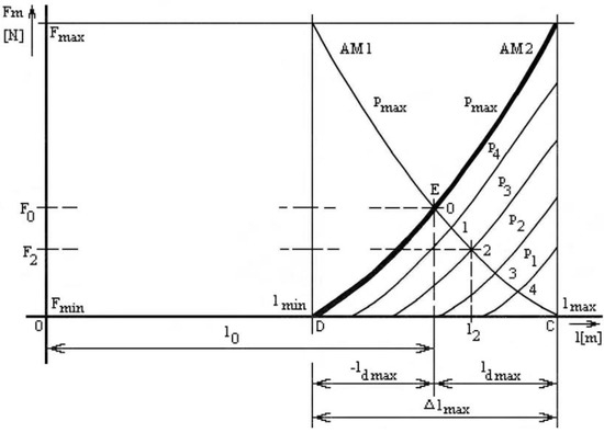
Figure 5.
Static properties of PAMs in antagonistic connection at variable filling pressure.
In the case of this artificial muscle, the air pressure does not change, so only one of its properties is depicted, the one corresponding to the initial filling pressure pm. The property is drawn so that it describes antagonistic forces of AM1 against AM2. The AM1 muscle serves as a non-linear pneumatic spring. This ensures equality of forces for every position of the positive position value. It also provides stiffness of the actuator’s mechanism. Property intersection points in the EC section correspond to the course of increasing concentration of the passive AM of AM1 during a gradual pressure decrease in the active AM of AM2. The above-described procedure facilitates achieving an arbitrary positive value ld (up to ldmax). Actuator’s negative position values are reached through the same procedure as described in the previous paragraph. Only the roles of individual muscles are switched. AM1 has a variable air pressure; AM2 serves as a non-linear pneumatic spring.
In the configuration of the antagonistic actuator, as shown in Figure 5 (position in the reference point E), while identical pneumatic artificial muscles are used, their non-linear functions gN will be identical too, as well as their tensile forces:
At the same time, the following applies: l1 = l2 = l0 and p1 = p2 = pm.
In the configuration of the antagonistic actuator, as shown in Figure 5, while identical pneumatic artificial muscles are used, their grids of non-linear functions gM will be identical, as well as their tensile forces (position in the reference point E):
while the following applies: l1 <> l2 and p1 <> p2 and kAM1 + kAM2 = kmax (kAM1 is contraction of the actuator AM1, kAM2 is contraction of the actuator AM2 and kmax is maximum contraction of the AMs antagonistic connection).
If in Equation (7), we know the non-linear function gM (l, p), then on the basis of the given equality of forces we can express the relationship between the output from the actuator (length l or ld) and its input (air pressure p) in the form of a non-linear function fN:
Equations (8) and (9) clearly indicate that the values of respective parameters β and ld will be achieved with a positive and a negative polarity. Therefore, the value of the input pressure p must also have assigned both polarities, despite the fact that the pressures into individual muscles have positive values (pAM1 > 0 and pAM2 > 0). This procedure is carried out depending on the sign of the required displacement of AM ldD or the required angular displacement βD as follows:
if sign βD = +, then p = pAM2.sign βD > 0 whereas sign β = + and pAM1 = const > 0,
if sign βD = −, then p = pAM1.sign βD < 0 whereas sign β = − and pAM2 = const > 0.
Such requirements for the angular displacement β apply also to the displacement of AM ld, instead of sign βD the requirements contain sign ldD:
if sign ldD = +, then p = pAM2.sign ldD > 0 whereas sign ld = + and pAM1 = const > 0,
if sign ldD = −, then p = pAM2.sign ldD < 0 whereas sign ld = − and pAM2 = const > 0.
The following shall apply to the total angular displacement of the actuator pulley shaft:
whereas the following applies to the displacement and the total length of the respective AM of the actuator:
additionally, the following applies to the magnitude of the actuator AM contraction k:
Displacement ld, as compared to the reference point E, will correspond to the intersection of relevant AM properties. For example, in Figure 5 they are points 1–4. The figure depicts a situation in which AM1 has a constant air pressure and the pressure of AM2 changes from the maximum to the zero value. At that moment, the actuator arm reaches the position of point C, i.e., the maximum positive displacement from the reference point E. The same procedure can also be applied in the case of opposite distribution of air pressures in the AM. Then, the actuator arm reaches the position of point D, i.e., the maximum negative displacement. With changing pressure in individual muscles, the working point of the actuator position will move from the initial reference point E along the relevant property with pressure pm either to point C or to point D.
4. Results and Discussion
4.1. Creation of the Model of Static Property of PAMs in Antagonistic Connection
The calculation of the function of the course of the measured static property of the actuator was carried out using the course of one half of the static property quadrant 1 (Figure 6) [33]. A general form of the equation for the solution of the linear regression task (by the method of least squares) in the matrix form for the basic form (without expressing the error) is:
and in the matrix form
with the dimensions Y = Nx1, X = Nx(1 + k), A = (1 + k)x1, where N is the number of measured values.
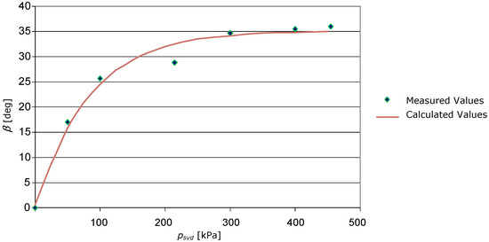
Figure 6.
Approximation of the actuator static characteristic by exponential function.
The selected function form was
If in the following expression of the relationship between the actuator arm displacement at the input air pressure into the AM, according to Function (17), we introduce for the given physical parameters by the substitution:
whereas the given parameters may have the following values:
The set of equations in the matrix form then has the following form
By solving this set of equations, the following values of coefficients were obtained for the used AMs
and therefore
As the antagonistic actuator with two AM moves, depending on the sign of pressure psvd in two directions from the initial (reference) point, corresponding to the equality of maximum pressures in both muscles, the static property of such an actuator will be four-quadrant and symmetric. It is assumed that the properties of both AMs are approximately the same.
4.2. Creation of the Model of the Dynamic Model Section
The model creation was based on experimental measurements of pressures in AMs and actuator rotation at various loads and at large step changes in the input pressure. Results of measurements are listed in Table 1 and graphical responses are in Figure 7. Results of measurements at various loads and at small step changes in the input pressure are listed in Table 2 and graphical responses are in Figure 8.

Table 1.
Values of pressures in MAS 20–250 and actuator rotation at large step changes of the input pressure.
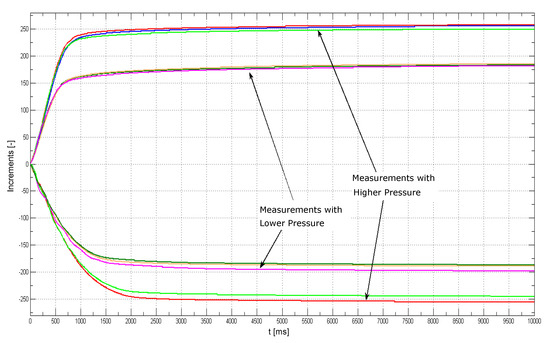
Figure 7.
The actuator responses measured at large step changes of the input pressure.
Table 2.
Values of pressures in MAS 20–250 and actuator rotation at small step changes of the input pressure.
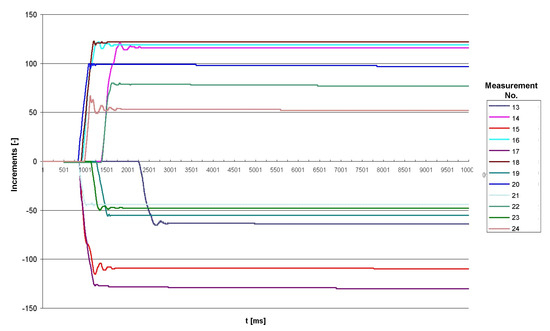
Figure 8.
The actuator responses measured at small step changes of the input pressure.
The comparison of actuator responses at low, moderate, and high input pressure values clearly indicates that in the case of first two types of input, the responses are monotonous, whereas at low inputs and the concurrent impact of a failure, these responses contain oscillations prior to the stabilisation. They are probably caused by the effects of the failure gravitation with a constant effect acting in the same direction causing, together with the air compressibility in the AM, the formation of a short-term damped marginal cycle prior to the stabilisation of the moment equilibrium on the actuator axis. Therefore, the determination of the mathematical model of the actuator dynamics was carried out while considering mainly the responses at great input changes, without the effects of failures; however, a general expression of the model must contain also the properties manifested at small inputs and failures.
The resulting transfer function would have the following form:
The model might be identified while applying the method of least squares (in a discrete form), provided that the differential equation is as follows:
where y(t) is the output from the system, a1, …, an are the output coefficients, u(t) is the input to the system, and b1, …, bm are input coefficients. The vector form is then as follows
where θ represents a parametric vector and ϕ(t) represents a regression vector. The task is to minimise the argument of the function by identifying relevant values of coefficients if (i.e., N input–output pairs), while applying the known procedure.
Then, we obtain
If we set the derivation as equal to zero and after editing, we obtain an estimation of the parametric vector
Then, the actuator can be described by the first order transfer function
or by the second order transfer function
Responses of the linear model of the first and second orders after the identification are presented in Figure 9.
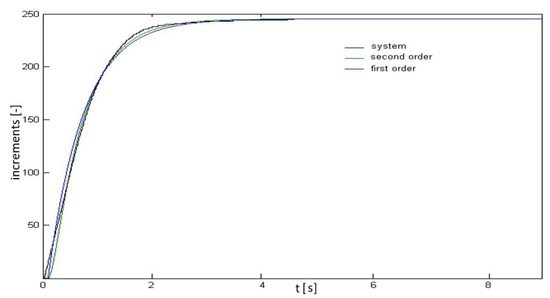
Figure 9.
Responses of the linear model of the first and second orders after the identification.
The actuator consisting of pneumatic artificial muscles in an antagonistic arrangement has, in each half of the angular displacement of the pulley shaft, regulated air pressure only in one artificial muscle. The other artificial muscle has a constant pressure and serves as a non-linear and pneumatic spring. Such an actuator is a non-linear system with the end position being a non-linear centrally symmetrical function of the filling air pressure in artificial muscles.
With decreasing pressure in the active AM, the angular displacement of the actuator pulley shaft increases along the curve with a decreasing inclination. The static property of such a system proves by its course that actuator strengthening depends on the arm’s position which depends on pressures and forces in individual artificial muscles. Actuator configuration, together with a simple control system, facilitates the construction of a rather simple positional servo system with adequate control requirements and execution costs.
Dependencies of the actuator end position represent a non-linear function of the filling air pressure in the artificial muscle and their courses are different at different values of actuator load. This follows from non-linear properties of artificial muscles. It is also necessary to respect a non-identical tensile force (or torque) of the actuator, the magnitude of which is changing with the value of angular displacement of the actuator pulley shaft (or artificial muscle contraction or displacement). This property also causes non-identical mechanism stiffness at different position values, whereas the highest and two-side symmetrical stiffness is reached in the reference point, when the pressures in the AMs are identical and reach the maximum.
5. Conclusions
The ability of artificial muscles to work in antagonistic connection facilitates the regulation of their own stiffness, thus providing a number of benefits in individual applications of actuators based on pneumatic artificial muscles. It offers the possibility to create various concepts for the control of systems comprising pneumatic artificial muscles and the use thereof in industry, under an assumption of minimum contact between the manipulation equipment and staff.
Mathematical modelling of PAM is important for the simulation of the dynamics of the movements of pneumatic actuators with artificial muscles, applied in the designing and execution stages, as well as for the creation of algorithms for the control of this type of actuators. In the creation of a mathematical model, it is important to know the geometrical properties of PAM and physical phenomena running inside the muscle. A significant role in PAM modelling is also played by the flexibility of materials used within the muscle assembly. Additionally, in this type of muscle, there is dry friction between the rubber tube and the braid; this indicates that PAM is regarded as a non-linear component with the insensitivity zone and hysteresis. Due to incomplete knowledge of all physical phenomena running inside the PAM, it is not possible to construct a perfect mathematical model thereof. It is therefore necessary to design deterministically a mathematical model of the lowest possible sensitivity to uncertainties, able to also provide the required responses in the event of changed parameters and failures.
Besides overcoming the forces from the load, the active muscle must also overcome the variable directive force of the passive muscle. That is why the requirements put on nominal parameters (tensile force) of artificial muscles are higher than those that would only be based on the load size. With regard to the need of appropriate mechanism stiffness, the forces of the actuator muscles are expected to be higher than the (maximum) load force.
Author Contributions
Conceptualization, T.Č.; methodology, D.M. (Darina Matisková), A.B. and D.M. (Daniela Marasová); validation, T.Č., A.B. and D.M. (Darina Matisková), formal analysis, D.M. (Daniela Marasová); investigation, A.B., T.Č. and D.M. (Darina Matisková); resources, D.M. (Daniela Marasová); data curation, T.Č. and A.B.; writing—original draft preparation, D.M. (Daniela Marasová); writing—review and editing, D.M. (Daniela Marasová) and A.B.; visualization, D.M. (Daniela Marasová) and A.B.; supervision, D.M. (Darina Matisková); project administration, D.M. (Darina Matisková) and D.M. (Daniela Marasová); funding acquisition, D.M. (Darina Matisková). All authors have read and agreed to the published version of the manuscript.
Funding
This research was funded by NATIONAL RESEARCH AGENCY OF SLOVAKIA, grant number VEGA 1/0393/18Research of Methods for Modeling and Compensation of Hysteresis in Pneumatic Artificial Muscles and PAM-actuated Mechanisms to Improve the Control Performance Using Computational Intelligence.
Institutional Review Board Statement
Not applicable.
Informed Consent Statement
Not applicable.
Data Availability Statement
Not applicable.
Acknowledgments
The article was written as a result of the successful solving of the Project of the Structural Funds of the EU, ITMS code: 26220220103.
Conflicts of Interest
The authors declare no conflict of interest.
References
- Čujan, Z.; Marasová, D. Evaluation of the Logistic process robotisation using the multiple-criteria decision-making. TEM J. 2018, 7, 501–506. [Google Scholar]
- Balara, M.; Dupláková, D.; Matisková, D. Application of a signal averaging device in robotics. Measurement 2018, 115, 125–132. [Google Scholar] [CrossRef]
- Dorf, C.R. Modern Control Systems, 3rd ed.; Addison-Wesley Longman: Boston, MA, USA, 1980; p. 425. [Google Scholar]
- Plettenburg, D.H. Pneumatic actuators: Comparison of energy-to-mass ratio’s. In Proceedings of the 9th International Conference on Rehabilitation Robotics, Chicago, IL, USA, 28 June–1 July 2005; pp. 545–549. [Google Scholar]
- Ramasamy, R.; Juhari, M.R.; Mamat, M.R.; Yaacob, S.; Mohd Nasir, N.F.; Sugisaka, M. An application of finite element modelling to pneumatic artificial muscle. Am. J. Appl. Sci. 2005, 2, 1504–1508. [Google Scholar] [CrossRef]
- Kerscher, T.; Albiez, J.; Zollner, J.M.; Dillman, R.F. Dynamic modeling of fluidic muscles using quick-release. In Proceedings of the 3rd International Symposium on Adaptive Motion in Animals and Machines, Ilmenau, Germany, 25–30 September 2005; pp. 1–6. [Google Scholar]
- Šitum, Ž. Pneumatic muscle as an actuator. Znan. Pop. Časopis Sustavi. 2009, 3, 54–60. (In Slovenian) [Google Scholar]
- Hosovsky, A.; Trojanova, M.; Piteľ, J.; Svetlik, J. Identification of DMSP-5 fluidic muscle dynamics using hammerstein model. In Proceedings of the IEEE 12th International Symposium on Applied Computational Intelligence and Informatics, Timisoara, Romania, 17–19 May 2018; pp. 319–324. [Google Scholar]
- Winters, J.M.; Savio, L.-Y.S. Multiple Muscle Systems: Biomechanics and Movement Organization; Springer: New York, NY, USA, 1990; ISBN 978-1-4613-9030-5. [Google Scholar]
- Yarlott, J.M. Fluid Actuator. US Patent No. 3645 173, 1972. [Google Scholar]
- Kukolj, M. Axially Contractable Actuator. US Patent US4733603A, 29 March 1988. [Google Scholar]
- Immega, G.; Kukolj, M. Axially Contractable Actuator. US Patent No. US4939982A, 10 July 1990. [Google Scholar]
- Sarosi, J.; Pitel, J.; Tothova, M.; Hosovsky, A.; Biro, I. Comparative survey of various static and dynamic models of pneumatic artificial muscles. Trans. Can. Soc. Mech. Eng. 2017, 41, 825–844. [Google Scholar] [CrossRef]
- Verrelst, B.; Daerden, F.; Lefeber, D.; Van Damme, M.; Vanderborght, B.; Van Ham, R.; Vermeulen, J. Pleated pneumatic artificial muscles for robotic application. In Proceedings of the Industry-Ready Innovative Research, 1st Flanders Engineering PhD Symposium, Brussels, Belgium, 11 December 2003; p. Mech11. [Google Scholar]
- Verrelst, B.; Daerden, F.; Lefeber, D.; Van Ham, R.; Fabr, T. Introducing Pleated pneumatic artificial muscles for the actuation of legged robots: A one-dimensional set-up. In Proceedings of the 3rd International Conference on Climbing and Walking Robots, Madrid, Spain, 2–4 October 2000; pp. 583–590. [Google Scholar]
- Ambrisko, L.; Cehlar, M.; Marasova, D. The rate of stable crack growth (scg) in automotive steels sheets. Metalurgija 2017, 56, 396–398. [Google Scholar]
- Ambrisko, Ľ.; Pesek, L. The stretch zone of automotive steel sheets. Sadhana 2014, 39, 525–530. [Google Scholar] [CrossRef]
- Villegas, D.; Michaël Van Damme, M.; Vanderborght, B.; Beyl, P.; Lefeber, D. Third–generation pleated pneumatic artificial muscles for robotic applications: Development and comparison with McKibben muscle. Adv. Rob. 2012, 26, 1–23. [Google Scholar] [CrossRef]
- Davis, S.; Caldwell, D.G. Braid effects on contractile range and friction modeling in pneumatic muscle actuators. Int. J. Rob. Res. 2006, 25, 359–369. [Google Scholar] [CrossRef]
- Serres, J.L. Dynamic Characterization of a Pneumatic Muscle Actuator and Its Application to a Resistive Training Device. Ph.D. Thesis, Wright State University, Dayton, OH, USA, 2008; p. 201. [Google Scholar]
- Mizakova, J.; Pitel’, J.; Tothova, M. Pneumatic artificial muscle as actuator in mechatronic system. Appl. Mech. Mater. 2014, 460, 81–90. [Google Scholar] [CrossRef]
- Wickramatunge, K.C.; Leephakpreeda, T. Study on mechanical behaviors of pneumatic artificial muscle. Int. J. Eng. Sci. 2009, 48, 188–198. [Google Scholar] [CrossRef]
- Trojanová, M.; Čakurda, T. Validation of the dynamic model of the planar robotic arm with using gravity test. MM Sci. J. 2020, 5, 4210–4215. [Google Scholar] [CrossRef]
- Hošovský, A.; Pitel’, J.; Židek, K.; Tóthová, M.; Sárosi, J.; Cveticanin, L. Dynamic characterization and simulation of two-link soft robot arm with pneumatic muscles. Mech. Mach. Theory 2016, 103, 98–116. [Google Scholar] [CrossRef]
- Tóthová, M.; Piteľ, J. Testing of two types of membership functions in fuzzy adaptive controller of pneumatic muscle actuator. In Proceedings of the 11th IEEE International Symposium on Applied Computational Intelligence and Informatics SACI 2016, Timișoara, Romania, 12–14 May 2016; pp. 497–502. [Google Scholar]
- Sárosi, J.; Piteľ, J.; Šeminský, J. Static force model-based stiffness model for pneumatic muscle actuators. Int. J. Eng. Res. Af. 2015, 18, 207–214. [Google Scholar] [CrossRef]
- Trojanová, M.; Čakurda, T.; Hošovský, A.; Krenický, T. Estimationof grey-box dynamic model of2-DOF pneumatic actuator robotic arm using gravity tests. Appl. Sci. 2021, 11, 4490. [Google Scholar] [CrossRef]
- Nezhad, M.N.; Korayem, A.H. Dynamic modeling of industrial manipulator Hyundai HS165 in order to determine the dynamic load-carrying capacity for a specified trajectory. In Proceedings of the 7th International Conference on Robotics and Mechatronics (ICRoM), Teheran, Iran, 20–21 November 2019; pp. 538–543. [Google Scholar]
- Al-Qahtani, H.M.; Mohammed, A.A.; Sunar, M. Dynamics and control of a robotic arm having four links. Arab. J. Sci. Eng. 2017, 42, 1841–1852. [Google Scholar] [CrossRef]
- Singh, S.; Singla, A.; Singh, A.; Soni, S.; Verma, S. Kinematic modelling of a five-DOFs spatial manipulator used in robot-assisted surgery. Perspect. Sci. 2016, 8, 550–553. [Google Scholar] [CrossRef][Green Version]
- Sung, H.; Lee, J.H.; Lee, C.; Seo, T.; Lee, J.W. Geometrical kinematic solution of serial spatial manipulators using screw theory. Mech. Mach. Theory 2017, 116, 404–418. [Google Scholar]
- Zidek, K.; Vasek, V.; Pitel, J.; Hošovsky, A. Auxiliary device for accurate measurement by the smartvision system. MM Sci. J. 2018, 1, 2136–2139. [Google Scholar] [CrossRef]
- Balara, A. The contribution to the enhancement of the computer aided methods of technology plant actuators movement. Diss. Work 2011, 149. (In Slovak) [Google Scholar]


Publisher’s Note: MDPI stays neutral with regard to jurisdictional claims in published maps and institutional affiliations. |
© 2021 by the authors. Licensee MDPI, Basel, Switzerland. This article is an open access article distributed under the terms and conditions of the Creative Commons Attribution (CC BY) license (https://creativecommons.org/licenses/by/4.0/).