
Influence of Local Properties on Fatigue Crack Growth of Laser Butt Welds in Thin Plates of High-Strength Low-Alloy Steel


Abstract
1. Introduction
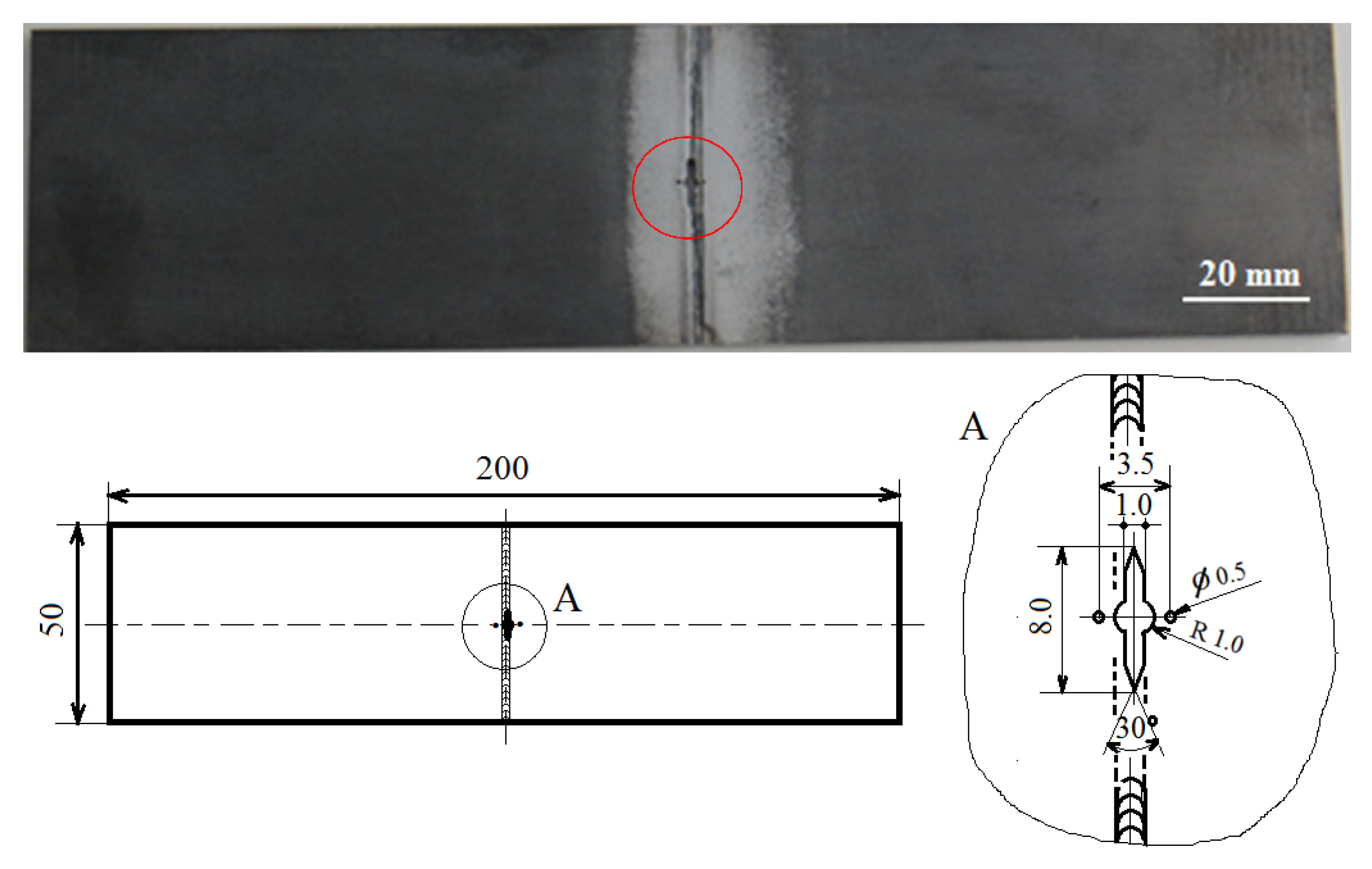
2. Materials and Methods
3. Results and Discussion
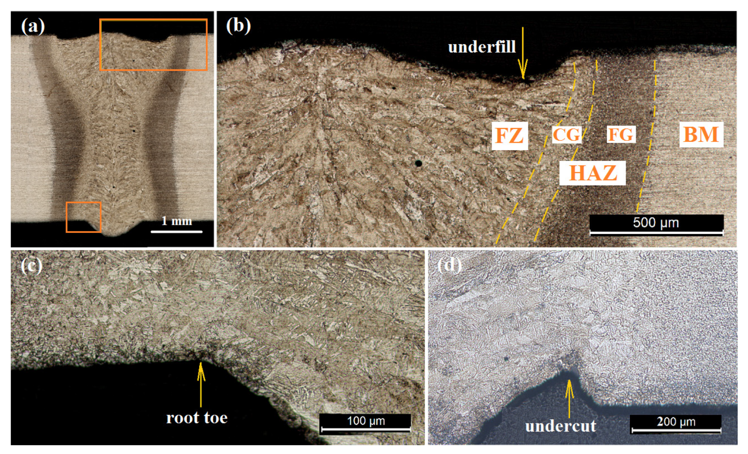
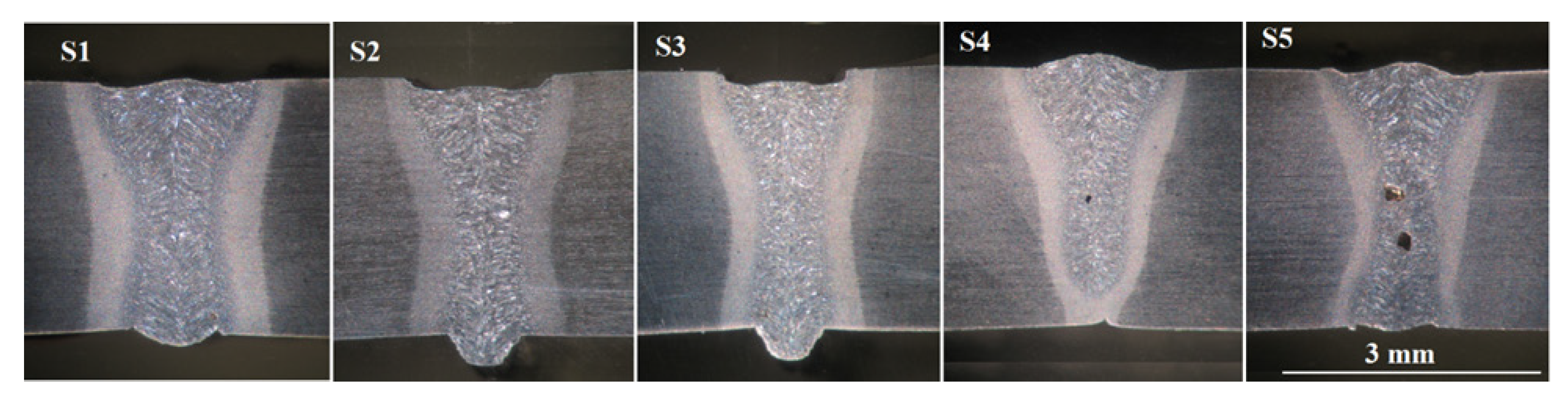
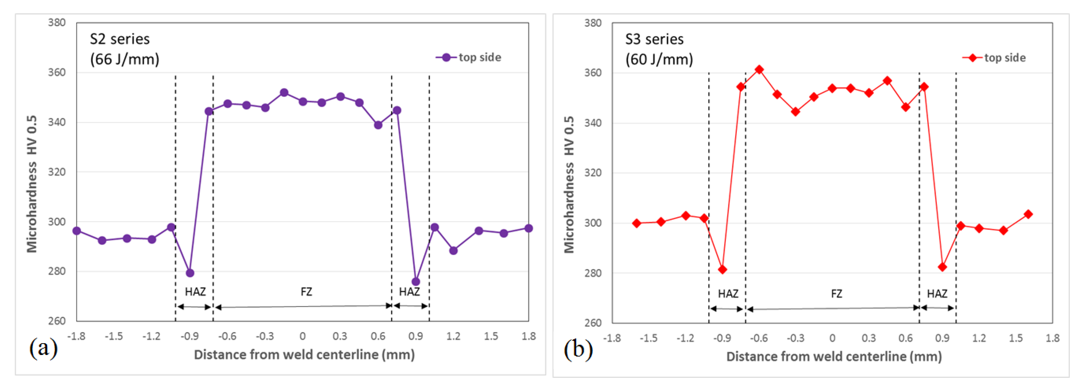
3.1. Welding Defects and Hardness
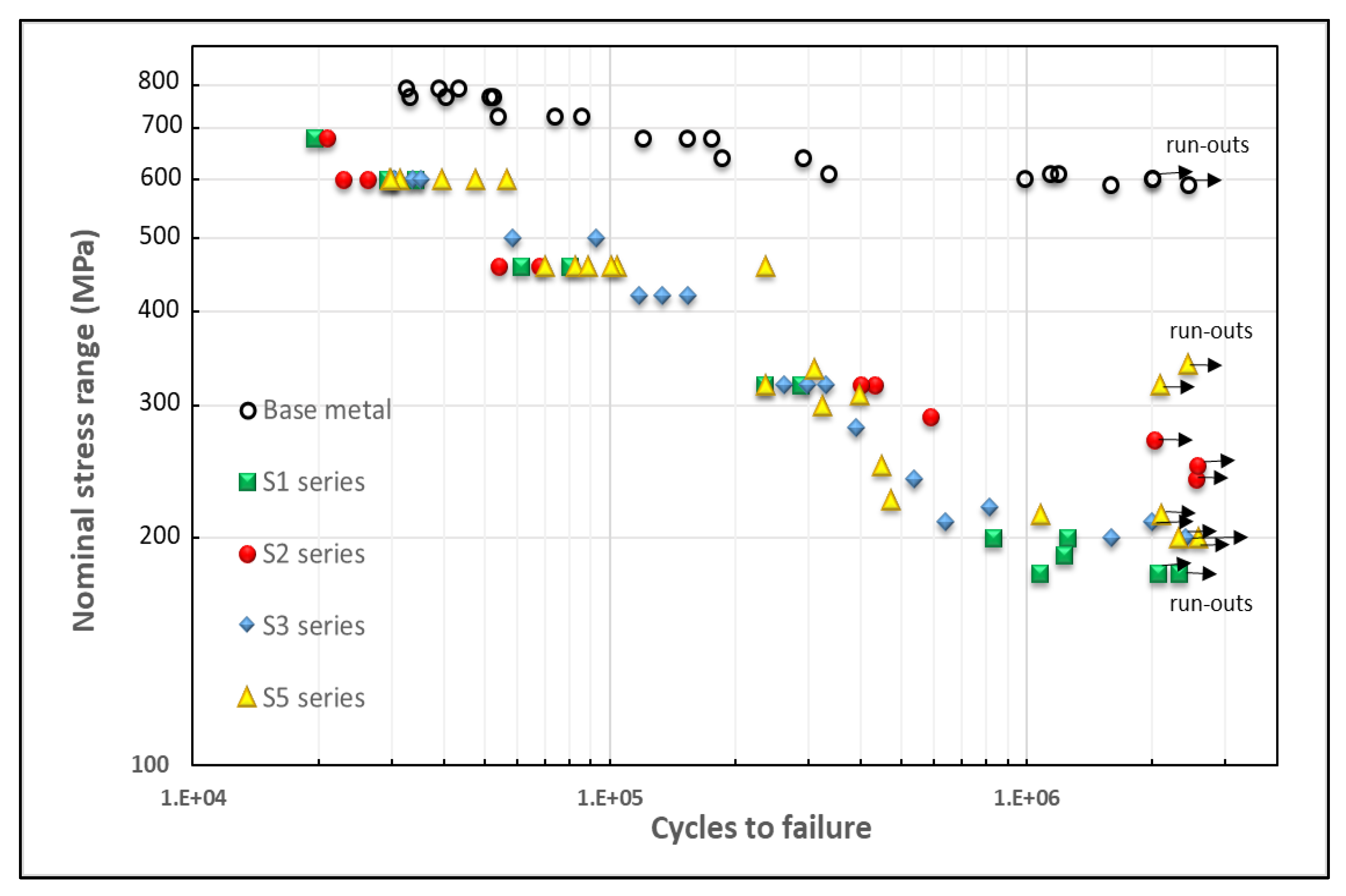
3.2. S–N Curves
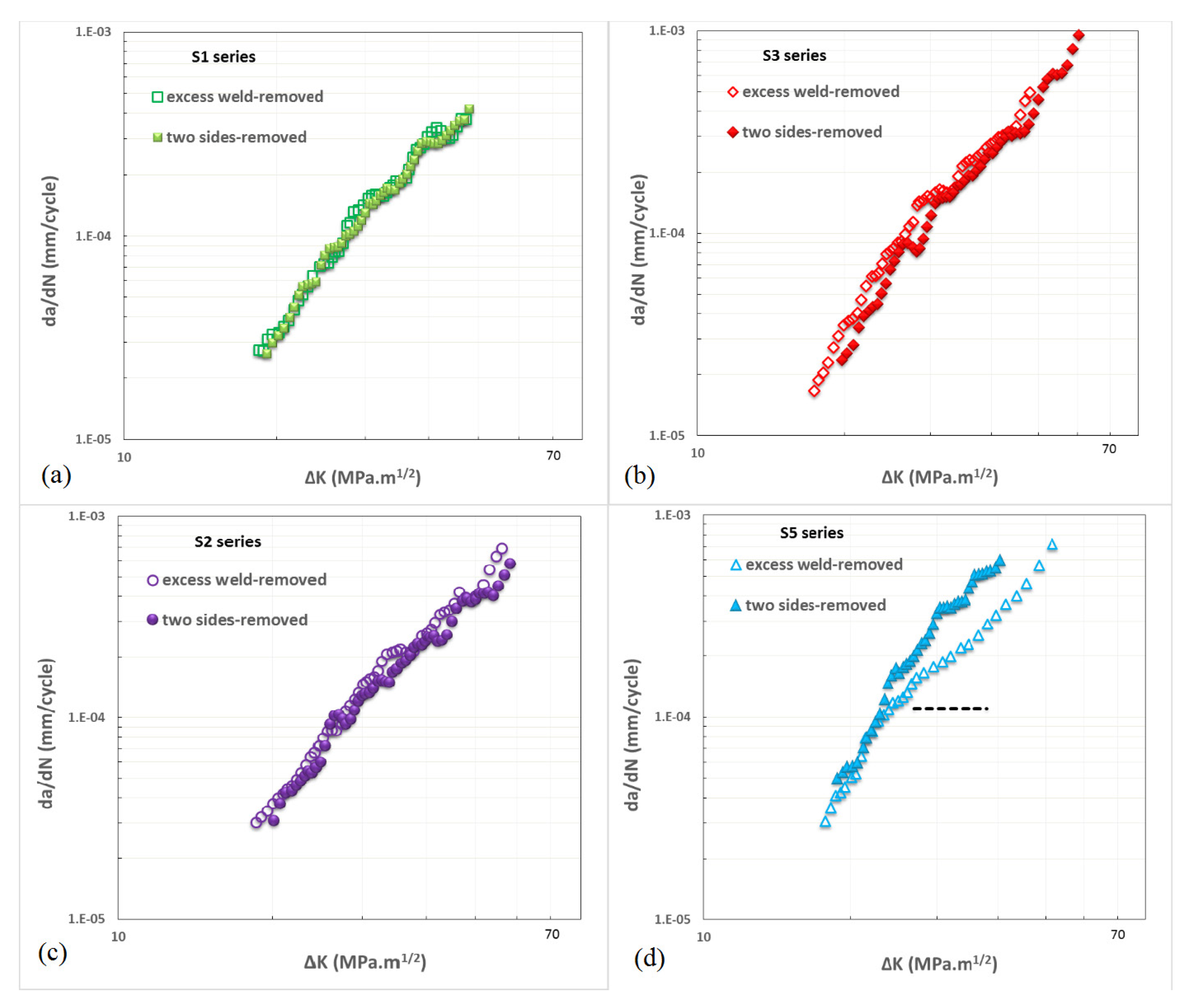
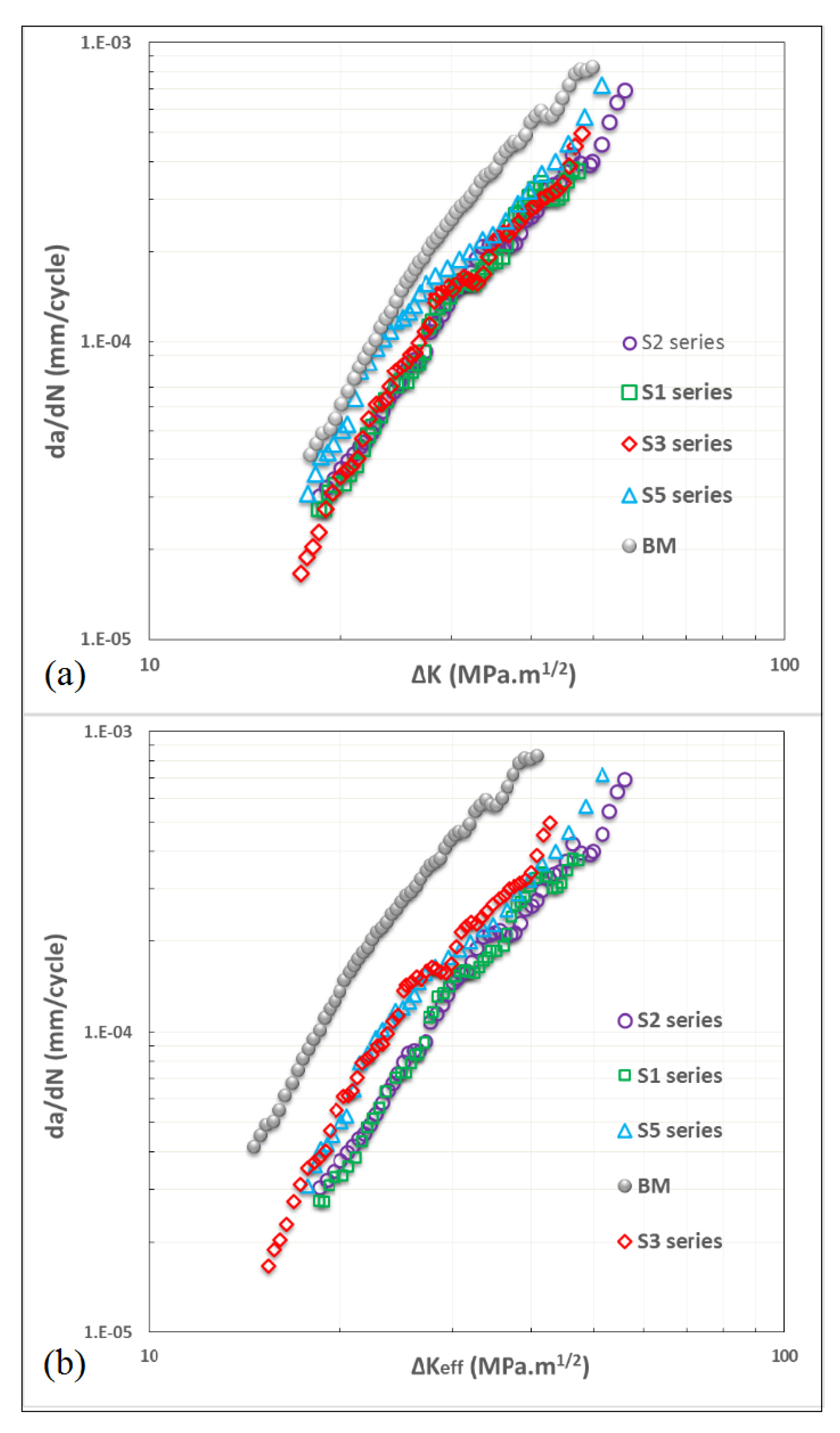
3.3. Fatigue Crack Growth
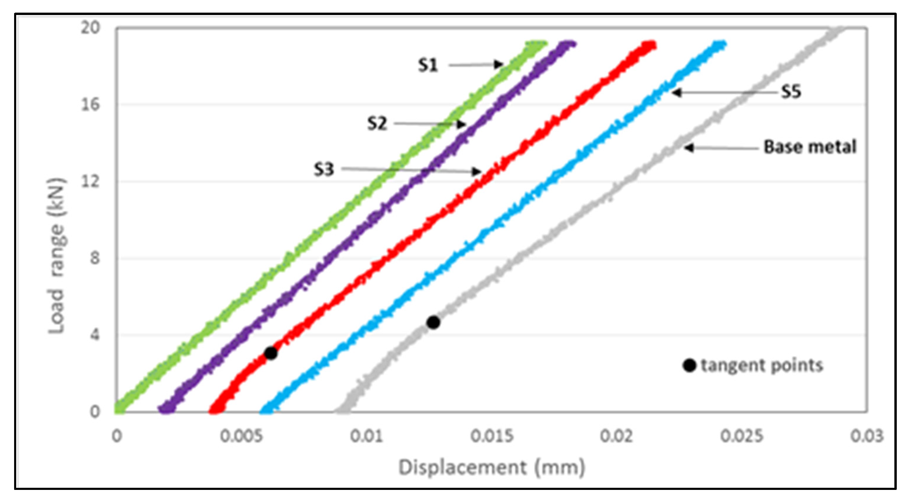
3.4. Crack Opening Displacement and Crack Closure
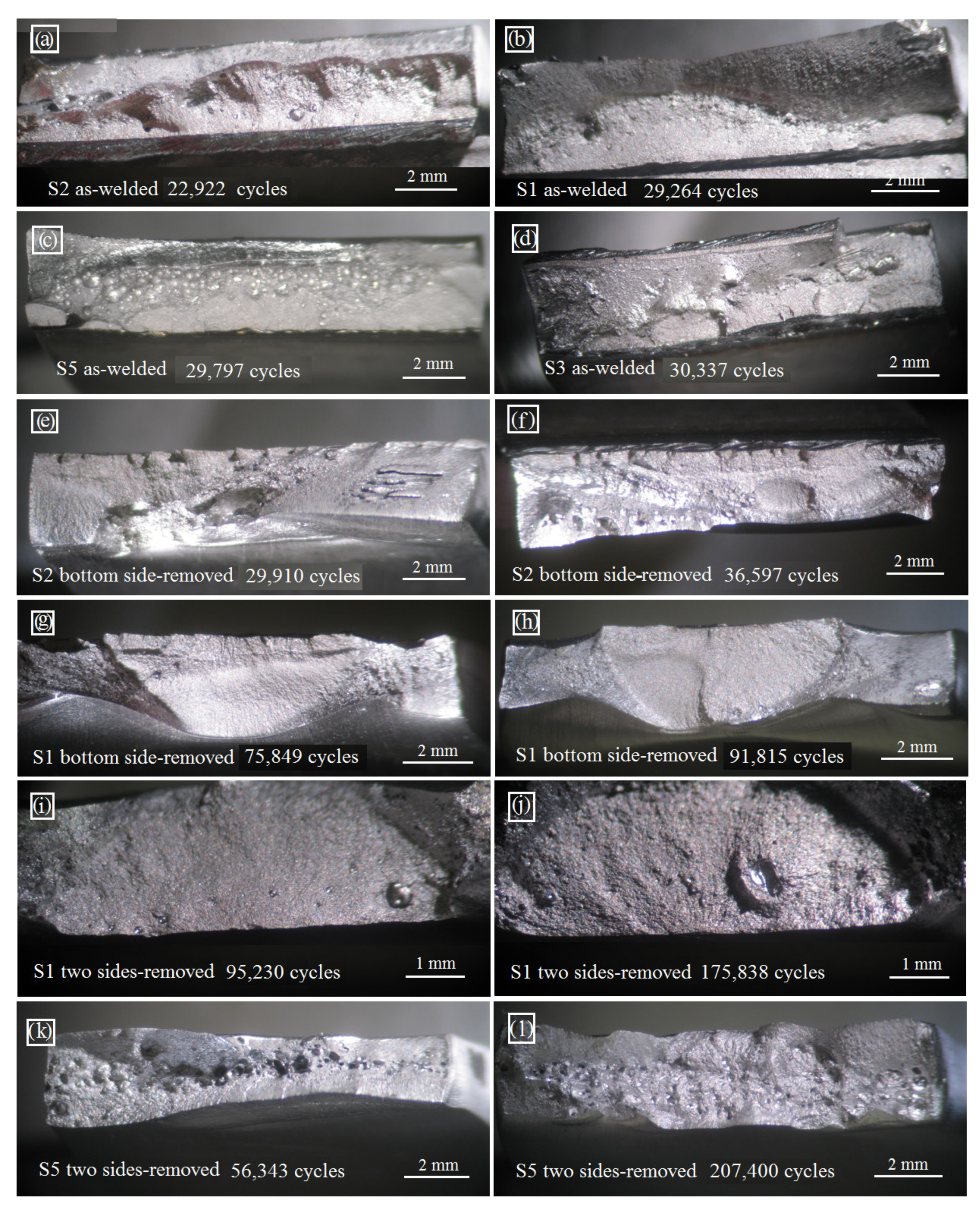
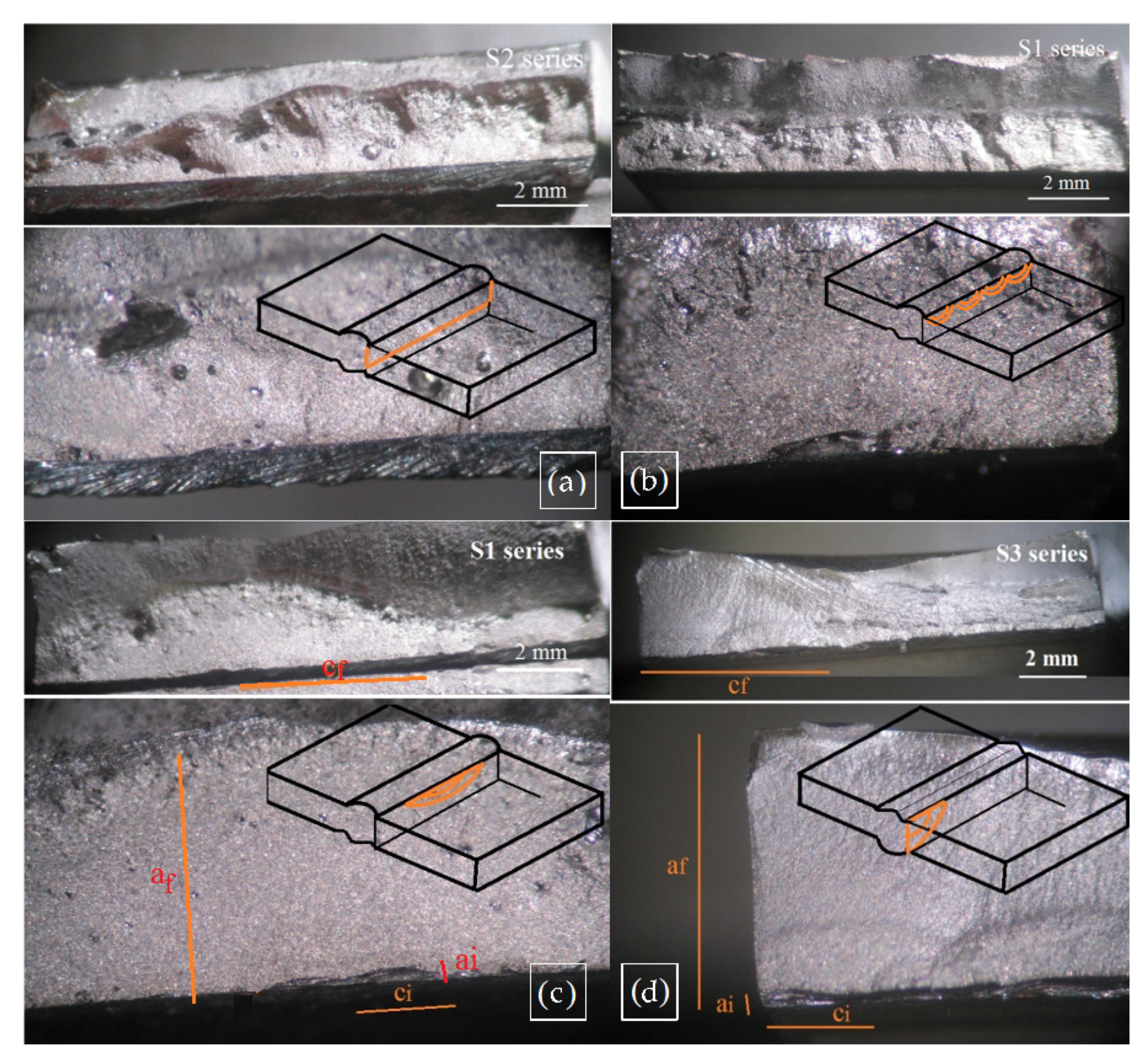
3.5. Effect of Imperfections at High Stress Levels
3.6. Fatigue Lives Predictions
4. Conclusions
- Although the differences were small, each welded series presented at the crack start and propagation sites (CGHAZ and FZ) had higher hardness than the BM. The hardness range for the welded series was 335–370 HV and the hardness for the BM was 295 HV;
- The welded series presented similar FCGR rates in the HAZFZ, but lower than in the BM. This was due to lower hardness being present in the BM because it was verified as a bainitic–ferritic microstructure, while, in the welded series it was observed as a bainitic–martensitic microstructure in the CGHAZ and the FZ. Crack closure was observed only in the BM and in the S3 series, which can be attributed mainly to the crack tip plasticity for the BM and the effect of compressive residual stresses for the S3 series. The welding parameters did not influence in the FCGR rates;
- At higher stress levels, fatigue life is strongly influenced by the quantity, size and location of the imperfections. The presence of crack-like imperfections located in critical positions, such as near to the lateral edge or several along the width of the specimen, favor the initiation and coalescence of cracks so that the fatigue initiation period can be neglected;
- It has been shown that estimations and predictions of welded series’ fatigue life are very sensitive to the adjustment of the initial crack size and the crack growth rates, and to an adequate identification of imperfections and assumptions of a type of superficial crack.
Author Contributions
Funding
Institutional Review Board Statement
Informed Consent Statement
Data Availability Statement
Acknowledgments
Conflicts of Interest
References
- Maddox, S.J. Fatigue Strength of Welded Structures; Abington Publishing: Cambridge, UK, 2002. [Google Scholar]
- Fricke, W. Fatigue strength assessment of local stresses in welded joints. In Fracture and Fatigue of Welded Joints and Structures; Woodhead Publishing: Cambridge, UK, 2011; pp. 115–138. [Google Scholar]
- Lieurade, H.P.; Huther, I.; Lefebvre, F. Effect of Weld Quality and Postweld Improvement Techniques on the Fatigue Resistance of Extra High Strength Steels. Weld. World 2008, 52, 106–115. [Google Scholar] [CrossRef]
- Gerritsen, C.; Vanrostenberghe, S.; Doré, M. Diode laser weld toe re-melting as a means of fatigue strength improvement in high strength steels. Procedia Eng. 2013, 66, 171–180. [Google Scholar] [CrossRef][Green Version]
- Cheng, X.; Fisher, J.; Prask, H.; Yen, B.; Graunapel-Herold, T.; Roy, S. Residual stress modification by post-weld treatment and its beneficial effect on fatigue strength of welded structures. Int. J. Fatigue 2003, 25, 1259–1269. [Google Scholar] [CrossRef]
- Lefebvre, F.; Peyrac, C.; Elbel, G.; Revilla-Gomez, C.; Verdu, C.; Buffière, J. Understanding of fatigue strength improvement of steel structures by hammer peening treatment. Procedia Eng. 2015, 133, 454–464. [Google Scholar] [CrossRef][Green Version]
- Marquis, G.; Barsoum, Z. A guideline for fatigue strength improvement of high strength steel welded structures using high frequency mechanical impact treatment. Procedia Eng. 2013, 66, 98–107. [Google Scholar] [CrossRef]
- Hobbacher, A.F. Recommendations for Fatigue Design of Welded Joints and Components; Springer: London, UK, 2016. [Google Scholar]
- Maddox, S. Fatigue Design Rules for Welded Structures, in Fracture and Fatigue of Welded Joints and Structures; Woodhead Publishing: Cambridge, UK, 2011; pp. 168–207. [Google Scholar]
- Lillemäe, I.; Remes, H.; Liinalampi, S.; Itävuo, A. Influence of weld quality on the fatigue strength of thin normal and high strength steel butt joints. Weld. Word 2016, 60, 731–740. [Google Scholar] [CrossRef]
- Watanabe, O.; Matsumoto, S.; Nakano, Y.; Saito, Y. Fatigue strength of welded joints in high strength steel Effects of stress concentration factor and welding residual stress. Weld. Int. 1996, 10, 201–206. [Google Scholar] [CrossRef]
- Harati, E.; Karlsson, L.; Svensson, L.-E.; Dalaei, K. The relative effects of residual stresses and weld toe geometry on fatigue life of weldments. Int. J. Fatigue 2015, 77, 160–165. [Google Scholar] [CrossRef]
- Nguyen, N.; Wahab, M. The Effect of Undercut and Residual Stresses on Fatigue Behaviour of Misaligned Butt Joints. Eng. Fract. Mech. 1996, 55, 453–469. [Google Scholar] [CrossRef]
- Shiozaki, T.; Yamaguchi, N.; Tamai, Y.; Hiramoto, J.; Ogawa, K. Effect of weld toe geometry on fatigue life of lap fillet welded ultra-high strength steels joints. Int. J. Fatigue 2018, 116, 409–420. [Google Scholar] [CrossRef]
- Kucharczyk, P.; Madia, M.; Zerbst, U.; Schork, B.; Gerwien, P.; Münstermann, S. Fracture-mechanics based prediction of the fatigue strength of weldments. Material aspects. Eng. Fract. Mech. 2018, 198, 79–102. [Google Scholar] [CrossRef]
- Ravi, S.; Balasubramanian, V.; Babu, S.; Nasser, S.N. Influences of MMR, PWHT and notch location on fatigue life of HSLA steel welds. Eng. Fail. Anal. 2004, 11, 619–634. [Google Scholar] [CrossRef]
- Wang, Q.; Yang, S.; Liu, X.; Dong, Z.; Fang, H. Understanding of fatigue crack growth behavior in welded joint a new generation Ni-Cr-Mo-V high strength steel. Eng. Fract. Mech. 2018, 194, 224–239. [Google Scholar] [CrossRef]
- Gurney, T. Cumulative Damage of Welded Joints; Woodhead Publishing Ltd: Cambridge, UK, 2006. [Google Scholar]
- Chapetti, M.; Jaureguizahar, L. Fatigue behavior prediction of welded joints by using an integrated fracture mechanics approach. Int. J. Fatigue 2012, 43, 43–53. [Google Scholar] [CrossRef]
- Zhang, Y.-H.; Maddox, S. Fatigue life prediction for toe ground welded joints. Int. J. Fatigue 2009, 31, 1124–1136. [Google Scholar] [CrossRef]
- Javaheri, E.; Hemmesi, K.; Tempel, P.; Farajian, M. Fatigue assessment of the welded joints containing process relevant imperfections. Weld. World 2019, 63, 249–261. [Google Scholar] [CrossRef]
- Goyal, R.; Bogdanov, S.; El-zein, M.; Glinka, G. Fracture mechanics based estimation of fatigue lives of laser welded joints. Eng. Fail. Anal. 2018, 93, 340–355. [Google Scholar] [CrossRef]
- Murakami, Y. Metal Fatigue: Effects of Small Defects and Nonmetallic Inclusions; Elsevier Science Ltd: Oxford, UK, 2002. [Google Scholar]
- Åman, M.; Tanaka, Y.; Murakami, Y.; Remes, H.; Marquis, G. Fatigue strength evaluation of small defect at stress concentration. Struct. Integr. Procedia 2017, 7, 351–358. [Google Scholar] [CrossRef]
- FITNET. FITNET Fitness-for-Service. Vol. II Annex; FITNET: Geesthacht, Germany, 2008. [Google Scholar]
- Zerbst, U.; Madia, M.; Schork, B.; Hensel, J.; Kucharczyk, P.; Ngoula, D.; Tchuindjang, D.; Bernhard, J.; Beckmann, C. Fatigue and Fracture of Weldments; Springer: Basilea, Switzerland, 2019. [Google Scholar]
- Riofrío, P.; Capela, C.; Ferreira, J. Imperfections and Modelling of the Weld Bead Profile of Laser Butt Joints in HSLA Steel Thin Plate. Metals 2021, 11, 151. [Google Scholar] [CrossRef]
- ISO. Welding-Electron and Laser-Beam Welded Joints-Guidance on Quality Levels for Imperfections. Part 1: Steel; ISO 13919-1(1996); ISO: Geneva, Switzerland, 1996. [Google Scholar]
- Riofrío, P.; Capela, C.; Ferreira, J.; Ramalho, A. Interactions of the process parameters and mechanical properties of laser butt welds in thin high strength low alloy steel plates. J. Mater. Des. Appl. 2020, 234, 665–680. [Google Scholar] [CrossRef]
- ASTM International. Standard Test Method for Measurement of Fatigue Crack Growth Rates. E647-13a (2013); ASTM International: West Conshohocken, PA, USA, 2013. [Google Scholar]
- Yisheng, W.; Schijve, J. Fatigue Crack Closure Measurements on 2024-T3 Sheet Specimens. Fatigue Fract. Eng. Mater. Struct. 1995, 18, 917–921. [Google Scholar] [CrossRef]
- Ohta, A.; Suzuki, N.; Maeda, Y.; Hiraoka, K.; Nakamura, T. Superior fatigue crack growth properties in newly developed weld metal. Int. J. Fatigue 1999, 21, S113–S118. [Google Scholar] [CrossRef]
- Chapetti, M.D.; Otegui, J.L. Importance of toe irregularity for fatigue resistance of automatic welds. Int. J. Fatigue 1995, 17, 531–538. [Google Scholar] [CrossRef]
- Guan, M.; Yu, H. Fatigue crack growth behaviors in hot-rolled low carbon steels: A comparison between ferrite–pearlite and ferrite–bainite microstructures. Mater. Sci. Eng. A 2013, 559, 875–881. [Google Scholar] [CrossRef]
- Li, S.; Khan, Y.; Kuang, S. Effects of microstructure on fatigue crack growth behavior in cold-rolled dual phase steels. Mater. Sci. Eng. A 2014, 612, 153–161. [Google Scholar] [CrossRef]
- Bell, R.; Vosikovsky, O.; Bain, S. The significance of weld toe undercuts in the fatigue of steel plate T-joints. Int. J. Fatigue 1989, 11, 3–11. [Google Scholar] [CrossRef]
- Kim, D.Y.; Hwang, I.; Jeong, G.; Kang, M.; Kim, D.; Seo, J.; Kim, Y. Effect of Porosity on the Fatigue Behavior of Gas Metal Arc Welding Lap Fillet Joint in GA 590 MPa Steel Sheets. Metals 2018, 8, 241. [Google Scholar] [CrossRef]
- Biswal, R.; Syed, A.; Zhang, X. Assessment of the effect of isolated porosity defects on the fatigue performance of additive manufactured titanium alloy. Addit. Manuf. 2018, 433–442, 23. [Google Scholar] [CrossRef]
- Schijve, J. Fatigue Predictions and Scatter. Fatigue Fract. Eng. Mater. Struct. 1994, 17, 381–393. [Google Scholar] [CrossRef]
- Verreman, Y.; Nie, B. Early Development of Fatigue Cracking at Manual Fillet Welds. Fatigue Fract. Eng. Mater. Struct. 1996, 19, 669–681. [Google Scholar] [CrossRef]
- Nair, P. Fatigue Crack Growth Model for Part-Througn Flaws in Plates and Pipes. J. Eng. Mater. Technol. 1979, 101, 53–58. [Google Scholar] [CrossRef]
- Lie, S.; Vipin, S.; Zhao, H. New weld toe magnification factors for semi-elliptical cracks in plate-to-plate butt-welded joints. Fatigue Fract. Eng. Mater. Struct. 2016, 40, 207–220. [Google Scholar] [CrossRef]


| C | Mn | Si | P | S | Cr | V | Nb | Ni | Cu | Al | Mo | Ti | Co | Fe |
|---|---|---|---|---|---|---|---|---|---|---|---|---|---|---|
| 0.07 | 1.69 | 0.01 | 0.012 | 0.006 | 0.03 | 0.02 | 0.046 | 0.04 | 0.011 | 0.044 | 0.016 | 0.117 | 0.016 | balance |
| Series | Laser Power (kW) | Welding Speed (m/min) | Heat Input (J/mm) |
|---|---|---|---|
| S1 | 2.00 | 1.60 | 75.0 |
| S2 | 1.75 | 1.60 | 65.6 |
| S3 | 2.00 | 2.00 | 60.0 |
| S4 | 1.75 | 2.00 | 52.5 |
| S5 | top side weld pass | ||
| 1.75 | 1.75–2.00 | 52.5–60.0 | |
| bottom side weld pass | |||
| 1.25 | 2.50 | 30.0 | |
| Series | linear Model | log C | m | Fatigue Limits |
|---|---|---|---|---|
| S1 | no rejected | 13.46 | 3.23 | 180 |
| S2 | no rejected | 16.21 | 4.25 | 270 |
| S3 | no rejected | 13.25 | 3.12 | 210 |
| S5 | no rejected | 13.47 | 3.21 | 215 |
| Series | A | n |
|---|---|---|
| S1 | 6 × 10⁻⁹ | 2.9147 |
| S2 | 1 × 10⁻⁸ | 2.7374 |
| S3 | 4 × 10⁻⁹ | 3.0276 |
| S5 | 2 × 10⁻⁸ | 2.6565 |
| BM | 2 × 10⁻⁸ | 2.9556 |
| Series-Crack Type (Figure) | Crack Sizes | FCGR Parameters 1 | Mk Factor | Y Value | Fatigue Life | |||
|---|---|---|---|---|---|---|---|---|
| ai, ci (mm) | af, cf (mm) | A*, n* | Experimental (Cycles) | Estimated (Cycles) | Ratio | |||
| S2-extended (Figure 10a) | 0.02, 12.5 | 0.96, 12.5 | 2 × 10⁻⁹, 3.2017 | 1.08 | 1.13 | 22,922 | 20,792 | 1.10 |
| S2-extended (Figure 10a) | 0.02, 12.5 | 1.22, 12.5 | 2 × 10⁻⁹, 3.2017 | 1.08 | 1.13 | 26,225 | 21,043 | 1.25 |
| S1-semi-elliptical (Figure 10b) | 0.15, 0.46 | 1.62, 2.61 | 7 × 10⁻¹⁰, 3.5965 | 1.05 | 1.10 | 29,264 | 25,485 | 1.15 |
| S1-semi-elliptical (Figure 10c) | 0.10, 0.69 | 2.01, 4.83 | 7 × 10⁻¹⁰, 3.5965 | 1.01 | 1.01 | 34,127 | 38,642 | 0.88 |
| S3-corner crack (Figure 10d) | 0.21, 1.15 | 3.00, 4.81 | 6 × 10⁻¹¹, 4.4175 | 1.00 | 1.15 | 33,762 | 35,065 | 0.96 |
| Series-Crack Type | Crack Sizes | Mk Factor | Y Value | Fatigue Life at 600 MPa | |||
|---|---|---|---|---|---|---|---|
| ai, ci (mm) | af, cf (mm) | Experimental (Cycles) | Predicted (Cycles) | Ratio | |||
| S1-semi-elliptical crack | 0.04, 0.56 | 0.96, 1.56 | 1.12 | 1.10 | 29,264 | 23,239 | 1.26 |
| S2-extended crack | 0.02, 12.5 | 1.5, 12.5 | 1.06 | 1.15 | 26,225 | 21,487 | 1.22 |
| S3-corner crack | 0.15, 1.58 | 3.00, 4.81 | 1.00 | 1.21 | 33,762 | 29,904 | 1.13 |
Publisher’s Note: MDPI stays neutral with regard to jurisdictional claims in published maps and institutional affiliations. |
© 2021 by the authors. Licensee MDPI, Basel, Switzerland. This article is an open access article distributed under the terms and conditions of the Creative Commons Attribution (CC BY) license (https://creativecommons.org/licenses/by/4.0/).
Share and Cite
Riofrío, P.G.; de Jesus, J.; Ferreira, J.A.M.; Capela, C. Influence of Local Properties on Fatigue Crack Growth of Laser Butt Welds in Thin Plates of High-Strength Low-Alloy Steel. Appl. Sci. 2021, 11, 7346. https://doi.org/10.3390/app11167346
Riofrío PG, de Jesus J, Ferreira JAM, Capela C. Influence of Local Properties on Fatigue Crack Growth of Laser Butt Welds in Thin Plates of High-Strength Low-Alloy Steel. Applied Sciences. 2021; 11(16):7346. https://doi.org/10.3390/app11167346
Chicago/Turabian StyleRiofrío, Patricio G., Joel de Jesus, José A. M. Ferreira, and Carlos Capela. 2021. "Influence of Local Properties on Fatigue Crack Growth of Laser Butt Welds in Thin Plates of High-Strength Low-Alloy Steel" Applied Sciences 11, no. 16: 7346. https://doi.org/10.3390/app11167346
APA StyleRiofrío, P. G., de Jesus, J., Ferreira, J. A. M., & Capela, C. (2021). Influence of Local Properties on Fatigue Crack Growth of Laser Butt Welds in Thin Plates of High-Strength Low-Alloy Steel. Applied Sciences, 11(16), 7346. https://doi.org/10.3390/app11167346