Article

Development of Wireless and Passive SAW Temperature Sensor with Very High Accuracy

1
Institute of Acoustics, Chinese Academy of Sciences, Beijing 100190, China
2
Electrical and Communication Engineering, School of Electronic, University of Chinese Academy of Sciences, Beijing 100049, China
3
Science and Technology on Reactor System Design Technology Laboratory, Nuclear Power Institute of China, Chengdu 610213, China
*
Authors to whom correspondence should be addressed.
Appl. Sci. 2021, 11(16), 7422; https://doi.org/10.3390/app11167422
Submission received: 24 June 2021 / Revised: 4 August 2021 / Accepted: 11 August 2021 / Published: 12 August 2021
(This article belongs to the Special Issue Wireless and Passive Surface Acoustic Wave Sensor)

Abstract

:
A surface acoustic wave (SAW) temperature sensor with high accuracy was developed and wirelessly characterized in this work. The sensing chip with reflective delay line pattern was simulated using typical coupling of modes (COM) model and prepared by the standard photolithographic technique. Sharp reflection peaks with high signal-to-noise (SNR) were observed from the developed sensing chip operating at 433 MHz. Referring to the frequency-stepped continuous wave (FSCW)-based transceiver, planar antennas, and the developed SAW chip, the wireless and passive temperature sensor system was built. Adaptive Least Mean Square (LMS) algorithm was used for the first time in the SAW sensor signal processing to significantly improve the system SNR, and the corresponding phase fluctuation is down to only 3 ° . High temperature sensitivity of 36.5 ° C and very high accuracy of ±0.2 ° C in the range of −30 ° C∼100 ° C were achieved successfully by wireless measurement.

1. Introduction

In the fields of precision chemistry, biomedicine and fine chemical industry, the accuracy of temperature detection impacts significantly on the quality of products [1,2]. For instance, the temperature measurement accuracy of chromatograph in chemical analysis requires ±0.1 ° C. Among the available temperature sensing technologies, the thermal resistance, thermocouple, and integrated temperature sensor technology are relatively mature and have the characteristics of high temperature measurement accuracy and stable performance [3,4,5]. However, the sensor must have a built-in battery or be powered by the power circuit, which cannot achieve passive detection. In addition, there are defects of poor anti-electromagnetic interference capability and large size. In this case, the surface acoustic wave (SAW) devices have attracted great interest because they feature high sensitivity, fast response, small size, etc. Another outstanding property is that the SAW device allows interrogating wirelessly without a battery as it is connected only by a radio frequency link to a transceiver. The above characteristics make it very promising in extreme, harsh, or unattended scenarios, such as contaminated surroundings, high voltage areas, and sealed environments. Many great efforts towards the wireless and passive SAW-based sensors were reported in recent literature [6,7,8,9,10,11]. Since the pioneering work proposed by X. Q. Bao and W. Burkhard [12], the SAW devices have been explored successfully for wirelessly temperature detection. A typical sensing system was composed of the SAW sensing device as the transponder, reader unit (transceiver), and the RF antennas connecting the transceiver and transponder [13]. The electromagnetic (EM) signal with characteristic frequency was emitted from the transceiver, received by the SAW transponder through the antenna, and transferred into SAW propagating along the piezoelectric substrate by the IDTs. The reflected SAW from the reflectors was retransmitted into the EM signal received by the transceiver. The changes in temperature modulate the SAW velocity owing to the thermal expansion effect of the piezoelectric substrate and corresponding shift in sensing device frequency ( Δ f) or phase ( Δ Φ ) is extracted as the sensing signal [14,15,16].
The pattern for the temperature sensor chip usually employs a one-port resonator or reflective delay line [17], as shown in Figure 1. The one-port resonator (Figure 1a) is composed of interdigital transducers (IDTs) and two reflectors positioned on each side of the IDTs. The reflective delay line pattern consists of an IDT and several reflectors positioned along the SAW propagation path. The temperature sensor using the one-port resonator pattern had been successfully applied to the health monitoring of power equipment. However, it is not easy to further improve the accuracy because of the limitation of the frequency sweep in the transceiver. For example, the sensitivity of a resonant pattern sensor is 1 KHz/ ° C. To achieve an accuracy of 0.1 ° C, the frequency sweep of the receiver should be below 100 Hz, but it is difficult to achieve. The reflective delay line pattern (Figure 1b) provides a way to improve the sensing accuracy by decoupling the phase signal, attracting more interest for high-accuracy temperature measurement. Corresponding temperature sensors have been frequently reported in recent literature. L. Reindl et al. proposed a well calibration towards the SAW sensor, which allows high accuracy better than 0.5 ° C [18]. Wang et al. conducted optimization towards the SAW sensing device with a multi-reflector delay line pattern and satisfactory accuracy of ∼0.8 ° C was achieved [19]. In addition, Zhao et al. proposed a multi-iteration-enhanced two-point simple moving average (MI-2P-SMA) method to reduce the measurement error. The results showed the relative error of the original temperature measurement data in the testing range of 40∼60 ° C is only ±0.15%, while the unprocessed data are −3.4% to 1.87% [20]. Huang et al. performed the median filtering algorithm to eliminate the noise of measurement data, and the temperature measurement error is reduced to ±0.6 ° C [21].
Despite the success stories about the temperature sensor employing reflective delay line pattern, they still suffer from the further improvement of the accuracy in a larger temperature range. In this work, an adaptive LMS filtering algorithm was utilized to eliminate the noise of the returned sensor signal and improve to accuracy. A method combining the multi-point parabola approximation and moving average approach was proposed to reduce the phase error. The sensing device operating at 433 MHz frequency was developed on YZ-cut LiNbO 3 using the photolithographic technique. Before device development, the coupling of modes (COM) model was performed to simulate the device performance. Referring to the FSCW-based transceiver and planar antenna, the wireless temperature sensing system was built, and wirelessly characterized by referring to the above algorithms. High sensitivity and excellent accuracy were achieved successfully.
The rest of this paper is organized as follows. In Section 2, the optimal design parameters of the sensor of the reflective delay line pattern are presented. The simulation of the optimization is based on the COM theory. In Section 3, the reflective delay line SAW temperature and wireless system are introduced. In Section 4, the signal processing methods for temperature sensing data are presented, including the adaptive LMS algorithm to improve SNR and the combination method of multi-point parabola approximation and moving average algorithm for reducing phase fluctuation. In Section 5, the temperature experiment for obtaining sensing data is presented. Fitting and relative error analysis are utilized for data analysis. Finally, in Section 6, the results are concluded.

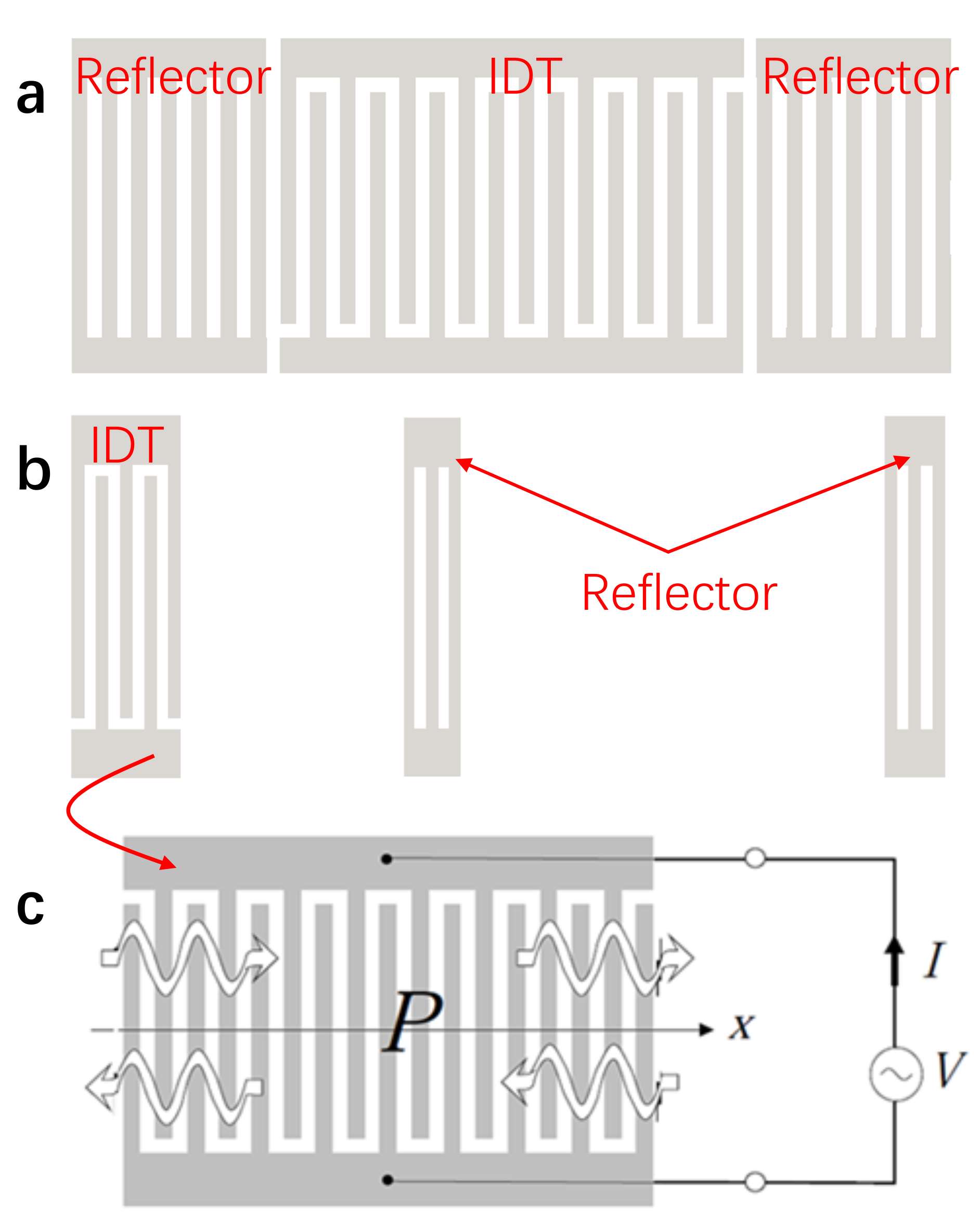
2. COM Simulation for Sensing Device

The reflective delay line is composed of an IDT and several reflectors positioned along the SAW propagation path. Larger SNR will contribute well to the improvement of wireless sensing performance [22]. To predict the performance of the sensing device, the typical COM model was employed [23,24].
In this work, a SAW device patterned by a reflective delay line with one IDT and two shorted reflectors was employed for sensing temperature, as shown in Figure 1b. The first reflector positioned ∼1.0 μ s away from the IDT in time domain to eliminate the noise from the testing environment. In addition, to obtain high temperature accuracy and SNR, the Y-cut Z-propagating Lithium Niobate (YZ LiNbO 3 ) substrate with a larger temperature coefficient (94 ppm/ ° C) and high electromechanical coupling coefficient (4.35%) was used to build the sensing chip. Hence, to conduct the SAW chip simulation by using the COM model, the COM equations towards IDT and shorted reflector were considered and solved, respectively. Corresponding mix (P) matrixes were deduced and cascaded. The reflection coefficient, S 11 , demonstrating the device performance, was denoted by [25]
S 11 = R 1 / P 33 R + 1 / P 33 ,
where P 33 denotes the admittance describing the acoustic and electrostatic currents due to the drive voltage, and R indicates the characteristic impedance of the device.
The COM model described above was used to simulate a reflective SAW delay line device operating at 433 MHz for sensing temperature prior to device development. Corresponding parameters for simulation are listed in Table 1. Obviously, the number 1 and 2 reflection peaks in Figure 2b were from the number 1 and 2 reflector in Figure 2a, respectively, and other peaks in Figure 2b were interference peaks, which were more than 30 dB compared with the former two reflection peaks, so they had almost no effect on temperature measurement. The difference of the interference peaks between the simulation and the experimental result may be caused by preparation technology, such as the unevenness of the substrate surface, the electrode difference in width, thickness, etc. Compared with the simulation result, larger SNR (more than 50 dB) was observed from the S 11 in the experimental result, as shown in Figure 2b.

3. Technique Realizations

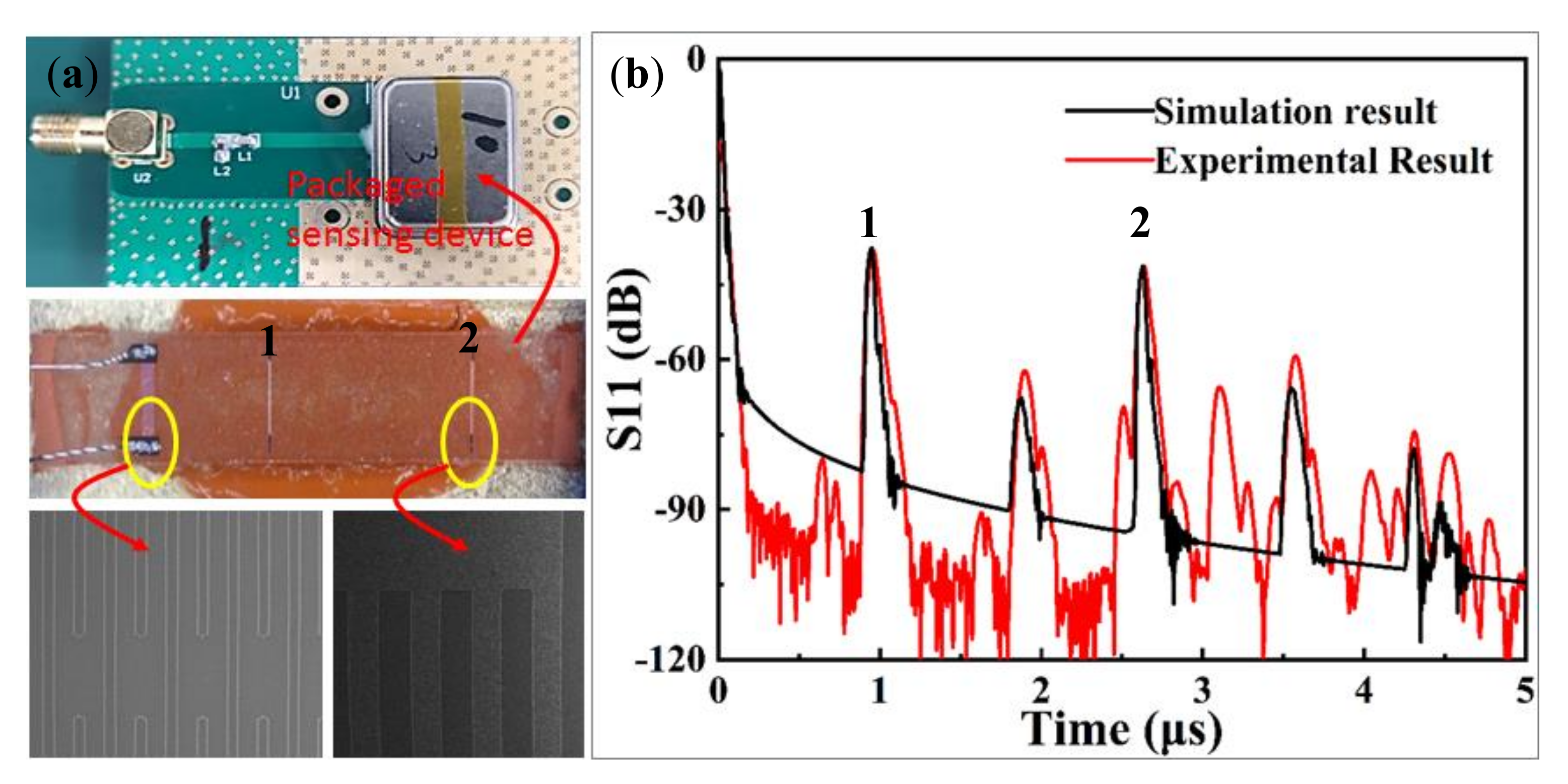
3.1. SAW Sensing Device

Using the standard photolithographic technique, the SAW sensing device with reflective delay line pattern was developed, and the design parameters were the same as that in Table 1. The corresponding fabrication procedure is depicted below. Aluminum with a thickness of 300 nm was evaporated onto the cleaned L i N b O 3 substrate surface. Then, a 1 mm thick photoresist (PR) was spin-coated, exposed, and developed for the reflective delay line pattern. Al was wert-etched, and PR was dissolved in acetone. The patterned wafer was dice-sawed after removing any unwanted products by several rinses with DI water. The developed SAW sensing device was packaged and connected to the dipole antenna for wireless measurement, as shown in depicted in Figure 2a. The fabricated sensor is characterized by using the network analyzer, larger SNR of ∼50 dB was achieved from the two reflection peaks in the time domain, and in addition, the positions of two reflection peaks in time domain were measured as ∼1 μ s and 2.6 μ s, which agrees well with the simulation, as shown in Figure 2b.

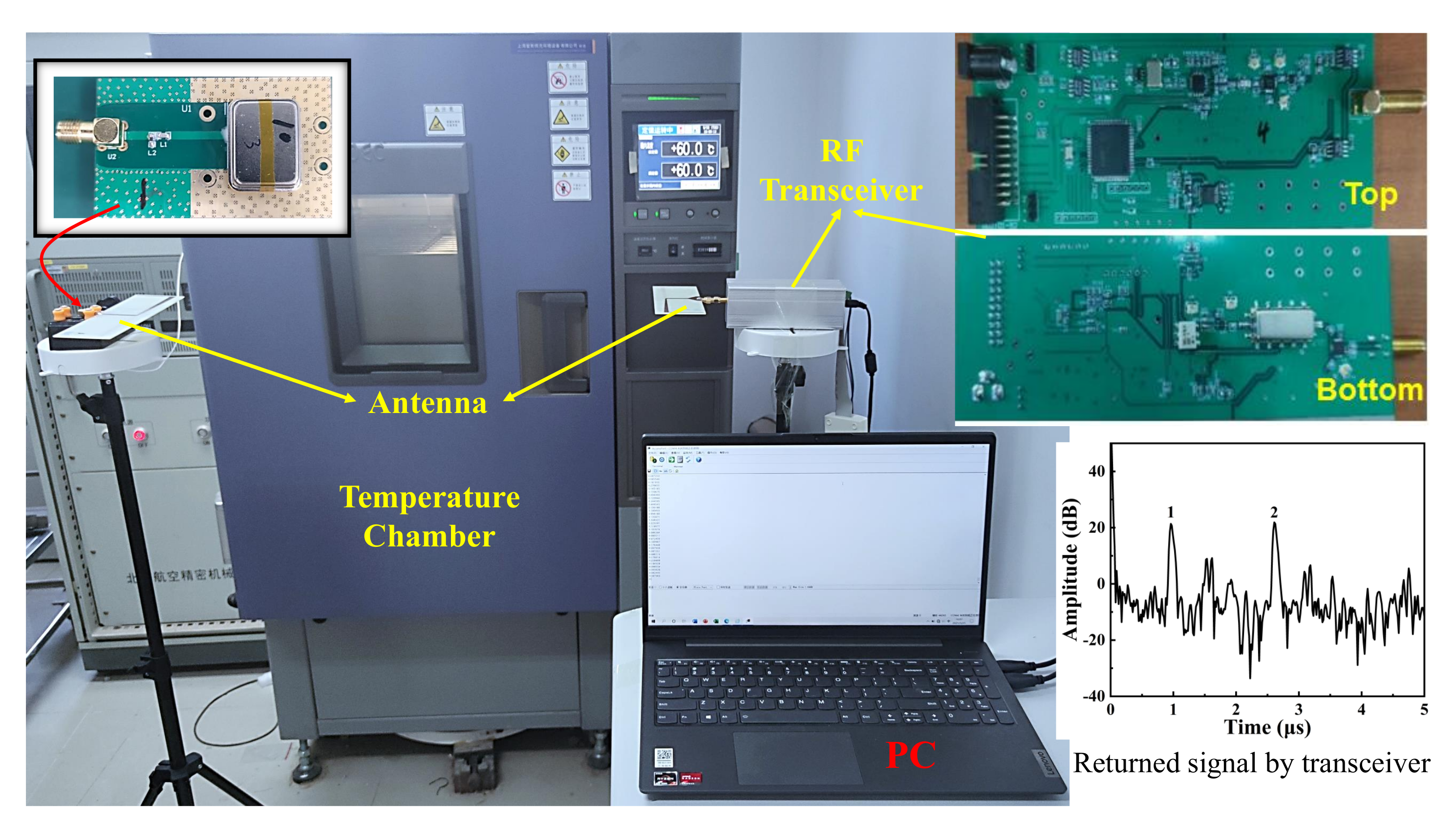
3.2. Wireless System

In this work, the transceiver, composed of transmitter and receiver modules, was developed by using stepped frequency modulation radar technology [26]. The former generated 400–450 MHz stepped frequency modulation signal, and the SAW sensor was awoken by receiving the electromagnetic wave (EW) signal. While the returned sensing signal was received by the latter, and corresponding sensing signal could be decoupled, and recorded in the computer. The built wireless system for sensing temperature was described in Figure 3, which was composed of the RF transceiver, SAW chip packaged as the transponder, RF antennas, the temperature chamber, and the computer for signal processing.
The sensing signal returned to the transceiver at wireless distance of 0.5 m and room temperature (20 ° C), which was depicted in Figure 3, and corresponding time positions of two reflection peaks were the same as that in Figure 2b.

4. Signal Processing Method

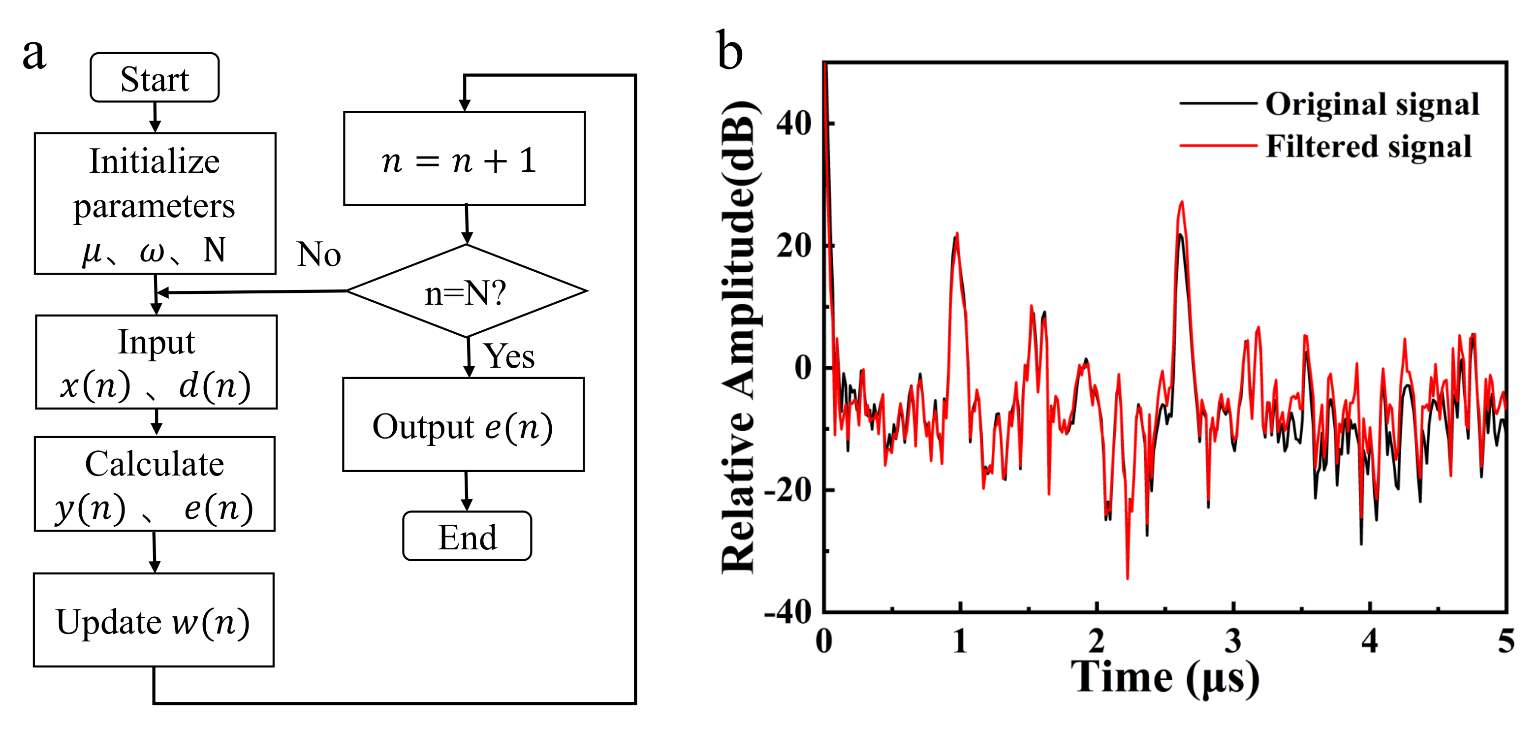
4.1. Adaptive LMS Algorithm

Obviously, the signals received in the wireless system contain not only temperature sensing signals but also various noises including baseline noise, quantization noise (±25 μ V) of active components in the circuit, and some unexpected reflected and scattered signals in the environment [27,28]. To obtain accurate temperature information, the received signals should be filtered to improve its SNR. The received signal was converted into a digital signal by sampling after filter, amplifier, and signal conditioning circuit of the receiving module. The amplitude of the digital signal is between 0.2∼3.1 V, and the number of data points is 800. Then, the time domain response can be obtained through fast FFT, and the reflection peak can be observed.
Considering that the noise characteristics of the signal are unknown and constantly changing, the filter should track the noise changes and constantly adjusting the filtering parameters to optimize the filtering effect. Therefore, the adaptive LMS filtering algorithm was employed to eliminate the noise [29], and low computational complexity, excellent convergence, and easy implementation are expected, which is appropriate in this work.
The output signal y ( n ) of the adaptive LMS filtering algorithm is defined by
y ( n ) = w T ( n ) x ( n ) ,
The error signal e ( n ) is denoted by
e ( n ) = d ( n ) y ( n ) ,
where d ( n ) denotes the expected signal and w T is the weight coefficient. The weight coefficient can be adjusted to adapt to the statistical characteristics of the changing signal and noise. The adjustment standard is to minimize the mean square value of the error between the expected signal and the filtered output signal. The recurrence relation of the weight coefficient is defined by
w ( n + 1 ) = w ( n ) μ e ( n ) x ( n ) ,
where μ represents the adaptive step size, which determines the stability and convergence speed of the algorithm.
Here, the sampled sensing signal was regarded as the expected signal d ( n ) , which contains both noise signal and sensing signal. The collected noise of the system was used as the input signal x ( n ) , which signifies that the noise signal is strongly correlated to the noise d ( n ) . The error signal e ( n ) was the desired filtered signal. The number of digital data points was taken as the N value. The flow chart of the specific filtering algorithm is shown in Figure 4a. The adjustable parameters of the filtering algorithm were determined by multiple debugging, and the adaptive step size ( μ ) and the filter order are 0.0001 and 150, respectively. Figure 4b indicates the comparison of responses in time domain before and after filtering. It can be seen that the signal peak sharpness corresponding to two reflectors increases significantly after filtering. In other words, the SNR of the system response of the sensor increased obviously after filtering.

4.2. Multi-Point Parabola Approximation and Moving Average Algorithm

To determine the precise time position of the reflection peak, the traditional method used the time–amplitude data of the peak point and its adjacent two points to obtain the fitting curve by parabola approximation method and then used the maximum point of the fitting curve to represent the peak point [30]. By extending this idea, a multi-point parabola approximation method was proposed to extract the peak position of single detection signal data by using the peak point and its adjacent four points. Distinctly, the result of the five-point parabola approximation is more accurate in the circumstances of high SNR. After that, to reduce the phase fluctuation of the peak points detected at a specific temperature, the 10-points moving average algorithm was used in signal processing. The moving average method is a simple smoothing algorithm. Based on time series data, the average value of a certain number of items can be calculated one by one. The method can effectively reduce the degree of phase fluctuation caused by random noise of the operating environment.
For the peak phase data from 100 wireless measurements at 20 ° C, the results of different algorithms are shown in Figure 5. For the combination method of multi-point parabola approximation and moving average algorithm, the phase fluctuation is about 3 ° . Meanwhile, the three-point parabola approximation and the five-point parabola approximation are about 12 ° and 8 ° , respectively. Therefore, the phase fluctuation of the proposed algorithm is only one-third of that of the previous algorithms.

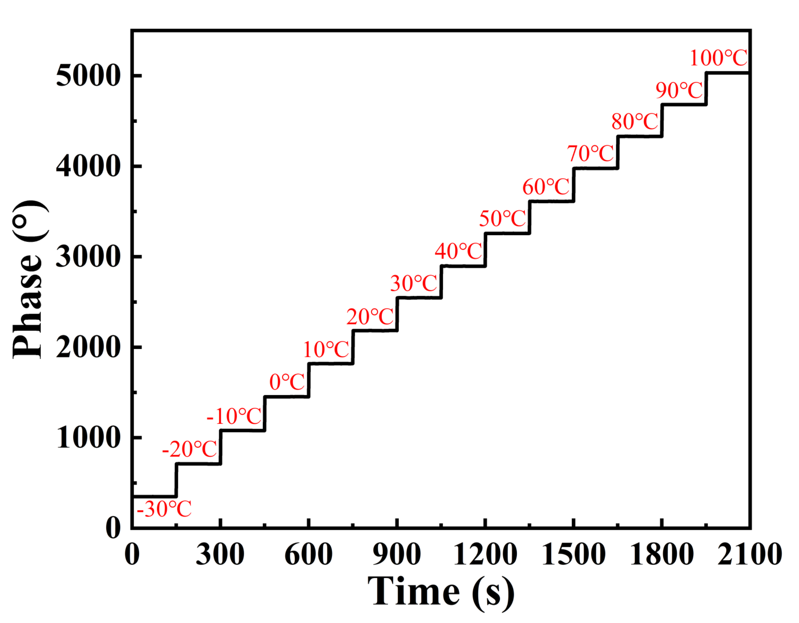
5. Sensing Experiment and Discussions

The experimental setup for sensing temperature was composed of a high and low temperature chamber and the developed SAW sensor system, as shown in Figure 3. The antenna distance was set to 0.5 m during the experiment. In the experiment, 14 temperature detection points were selected from −30 ° C to 100 ° C with equal intervals of 10 ° C. To determine the number of data available, 150 tests were carried out at each temperature point in the experiments. The dynamic response of the sensor in the temperature range was recorded in Figure 6. Obviously, as the temperature increases, the phase of the signal gradually increases.
The calibration curve of the sensor response of the proposed temperature sensor is shown in Figure 7a. The results were calculated from the 1500 sets of temperature measurement data, and each set of data includes 800 original data points. Higher sensitivity of 36.5 ° / ° C was achieved. In addition, the temperature value displayed in the temperature chamber was taken as the true value of the temperature, and then the experimental test value was compared with it to evaluate the temperature measurement accuracy of the system. As shown in Figure 7b, within the range of −30 ° C ∼ 100 ° C, the temperature measurement error of the system is less than 0.2 ° C, which means higher accuracy of ±0.2 ° C in temperature measurement was achieved successfully. The achieved accuracy from the proposed SAW sensor was better than that of the similar works listed in Table 2. It means the adaptive LMS filtering algorithm and the combination method proposed in this work contributes greatly towards improving the accuracy in temperature measurement. In addition, low-temperature (below 0 ° C) detection was carried out in this work, which was ignored in other work. Theoretically, it is possible to detect up to 300 ° C because the thermostat at high temperature cannot display precisely the true internal temperature. Therefore, the range is −30∼100 ° C in this work.

6. Conclusions

A signal processing algorithm of LMS was employed to improve the accuracy of a wireless and passive SAW temperature sensor in this work. The SAW sensing device with reflective delay line pattern was simulated by the COM model and prepared by the standard photolithographic technique on YZ-cut LiNbO 3 piezoelectric substrate and larger SNR of ∼50 dB was obtained. Adaptive LMS algorithm and the combination method of multi-point parabola approximation and moving average algorithm were used to reduce the peak phase fluctuation and significantly improve the accuracy, which was confirmed by wireless temperature measurement. The developed wireless and passive temperature sensor system consisted of the frequency-stepped continuous wave (FSCW)-based transceiver, the planar antennas, and the prepared SAW chip. The wireless temperature tests were conducted. High sensitivity of 36.5 ° / ° C and excellent accuracy of ±0.2 ° C were achieved successfully.

Author Contributions

X.G., L.C., X.X., and S.Z. carried out the experiment. X.G. and L.C. wrote the manuscript with support from X.X., W.W., M.L., and Z.L., X.G., and X.X. performed the analytic calculations and performed the numerical simulations. Y.L., X.X., W.W., and J.Z. fabricated the samples.All authors have read and agreed to the published version of the manuscript.

Funding

This research was funded by the project of knowledge at the National Key Research and Development Project, grant number [2018YFB2002500], and the NSFC Joint Key Fund Project, grant number U1837209, 11774381.

Conflicts of Interest

The authors declare no conflict of interest.

References

  1. Ming, W.W.; Yao, Z.; Wen, Q.G.; Li, Q.H.; Qin, J.L. Design of the Chemical Reaction Tank Temperature Acquisition System Based on Wireless Sensor Networks. Adv. Mater. Res. 2014, 945–949, 1982–1986. [Google Scholar] [CrossRef]
  2. Zhang, X.; Xuehui, H.U.; Zhai, Y.; Qin, C. The Design and Experimental Study of High Precise Temperature Acquisition System Based on PT100. Chuangan Jishu Xuebao 2010, 23, 812–815. [Google Scholar]
  3. Tan, Q.; Luo, T.; Wei, T.; Liu, J.; Lin, L.; Xiong, J. A Wireless Passive Pressure and Temperature Sensor via a Dual LC Resonant Circuit in Harsh Environments. J. Microelectromech. Syst. 2017, 26, 351–356. [Google Scholar] [CrossRef]
  4. Yan, D.; Yang, Y.; Hong, Y.; Liang, T.; Yao, Z.; Chen, X.; Xiong, J. Low-Cost Wireless Temperature Measurement: Design, Manufacture, and Testing of a PCB-Based Wireless Passive Temperature Sensor. Sensors 2018, 18, 532. [Google Scholar] [CrossRef] [PubMed] [Green Version]
  5. Yan, D.; Yong, Y.; Hong, Y.; Liang, T.; Yao, Z.; Chen, X.; Xiong, J. AlN-Based Ceramic Patch Antenna-Type Wireless Passive High-Temperature Sensor. Micromachines 2017, 8, 301. [Google Scholar] [CrossRef] [Green Version]
  6. Wang, W.; Xue, X.; Fan, S.; Liu, M.; Lu, M. Development of a wireless and passive temperature-compensated SAW strain sensor. Sens. Actuators A 2020, 308, 112015. [Google Scholar] [CrossRef]
  7. Paquit, M.; Arapan, L.; Feng, W.; Friedt, J.M. Long Range Passive RADAR Interrogation of Subsurface Acoustic Passive Wireless Sensors Using Terrestrial Television Signals. IEEE Sens. J. 2020, 20, 7156–7160. [Google Scholar] [CrossRef]
  8. Devkota, J.; Greve, D.W.; Hong, T.; Kim, K.J.; Ohodnicki, P.R. An 860 MHz Wireless Surface Acoustic Wave Sensor with a Metal-Organic Framework Sensing Layer for CO2 and CH4. IEEE Sens. J. 2020, 20, 9740–9747. [Google Scholar] [CrossRef]
  9. Rabus, D.; Friedt, J.M.; Arapan, L.; Lamare, S.; Cherioux, F. Sub-surface H2S detection by a Surface Acoustic Wave passive wireless sensor interrogated with a ground penetrating radar. ACS Sens. 2020, 5, 1075–1081. [Google Scholar] [CrossRef] [PubMed]
  10. Li, B.; Yassine, O.; Kosel, J. A Surface Acoustic Wave Passive and Wireless Sensor for Magnetic Fields, Temperature, and Humidity. IEEE Sens. J. 2014, 15, 453–462. [Google Scholar] [CrossRef]
  11. Pan, Y.; Qin, M.; Guo, T.; Zhang, L.; Xue, X. Wireless passive surface acoustic wave (SAW) technology in gas sensing. Sens. Rev. 2021, 41, 135–143. [Google Scholar] [CrossRef]
  12. Bao, X.Q.; Burkhard, W.; Varadan, V.V.; Varadan, V.K. SAW Temperature Sensor and Remote Reading System. In Proceedings of the IEEE 1987 Ultrasonics Symposium, Denver, CO, USA, 14–16 October 1987; pp. 583–586. [Google Scholar] [CrossRef]
  13. Xu, F.Q.; Wang, W.; Xue, X.F.; Hu, H.L.; Liu, X.L.; Yong, P. Development of a Wireless and Passive SAW-Based Chemical Sensor for Organophosphorous Compound Detection. Sensors 2015, 15, 30187–30198. [Google Scholar] [CrossRef] [PubMed] [Green Version]
  14. Kuypers, J.H.; Reindl, L.M.; Tanaka, S.; Esashi, M. Maximum accuracy evaluation scheme for wireless saw delay line sensors. IEEE Trans. Sonics Ultrason. 2008, 55, 1640–1652. [Google Scholar] [CrossRef] [PubMed]
  15. Yudytskiy, M.; Fachberger, R. Continuous temperature monitoring algorithm for SAW sensors. IEEE Int. Ultrason. Symp. 2015, 1–4. [Google Scholar] [CrossRef]
  16. Kim, J.; Luis, R.; Smith, M.S.; Figueroa, J.A.; Malocha, D.; Nam, B.H. Concrete temperature monitoring using passive wireless surface acoustic wave sensor system. Sens. Actuators A 2015, 224, 131–139. [Google Scholar] [CrossRef]
  17. Kalinin, V. Passive wireless strain and temperature sensors based on SAW devices. In Proceedings of the 2004 IEEE Radio and Wireless Conference, Atlanta, GA, USA, 22 September 2004; pp. 187–190. [Google Scholar] [CrossRef]
  18. Fachberger, R.; Bruckner, G.; Hauser, R.; Reindl, L. Wireless SAW based high-temperature measurement systems. In Proceedings of the 2006 IEEE International Frequency Control Symposium and Exposition, Miami, FL, USA, 4–7 June 2006; pp. 358–367. [Google Scholar] [CrossRef]
  19. Wang, W.; Xue, X.; Shao, X.; Wang, J.; Liang, Y. Development of a surface acoustic wave wireless and passive temperature sensor incorporating reflective delay line. Chin. J. Acous. 2014, 39, 473–478. [Google Scholar] [CrossRef]
  20. Tang, Z.; Wu, W.; Gao, J.; Luo, J.; Xu, L. A Multi-Iteration Enhanced 2P-SMA Method for Improved Error Reduction on a WP-SAW Water Temperature and Pressure Sensor. IEEE Access 2021, 9, 48236–48243. [Google Scholar] [CrossRef]
  21. Huang, D.; Li, T. Design of RF temperature measurement system of delay linear SAW temperature sensor based on FPGA. In Proceedings of the 2020 International Conference on Computer Engineering and Application (ICCEA), Guangzhou, China, 18–20 March 2020; pp. 520–524. [Google Scholar] [CrossRef]
  22. Rodriguez, L.M.; Gallagher, D.R.; Gallagher, M.W.; Fisher, B.H.; Humphries, J.R.; Malocha, D.C. Wireless SAW Sensor Temperature Extraction Precision. IEEE Sens. J. 2014, 14, 3830–3837. [Google Scholar] [CrossRef]
  23. Wen, W.; Lee, K.; Woo, I.; Park, I.; Yang, S. Optimal design on SAW sensor for wireless pressure measurement based on reflective delay line. Sens. Actuators A 2007, 139, 2–6. [Google Scholar] [CrossRef]
  24. Lee, K.; Wang, W.; Kim, T.; Yang, S. A novel 440 MHz wireless SAW microsensor integrated with pressure–temperature sensors and ID tag. J. Micromech. Microeng. 2007, 17, 515–523. [Google Scholar] [CrossRef]
  25. Hashimoto, K.Y. Surface Acoustic Wave Devices in Telecommunications. In Modelling and Simulation; Springer: Berlin/Heidelberg, Germany, 2000. [Google Scholar]
  26. Bulst, W.E.; Fischerauer, G.; Reindl, L. State of the art in wireless sensing with surface acoustic waves. IEEE Trans. Ind. Electron. Control Instrum. 2001, 48, 265–271. [Google Scholar] [CrossRef]
  27. Liu, B.; Han, T.; Zhang, C. Error Correction Method for Passive and Wireless Resonant SAW Temperature Sensor. IEEE Sens. J. 2015, 15, 3608–3614. [Google Scholar] [CrossRef]
  28. Zhang, Y.; Wang, R.; Li, S.; Qi, S. Temperature Sensor Denoising Algorithm Based on Curve Fitting and Compound Kalman Filtering. Sensors 2020, 20, 1959. [Google Scholar] [CrossRef] [PubMed] [Green Version]
  29. Widrow, B.; Hoff, M.E. Adaptive switching circuits. Neurocomputing 1960, 4, 126–134. [Google Scholar]
  30. Reindl, L.; Shrena, I.; Kenshil, S.; Peter, R. Wireless measurement of temperature using surface acoustic waves sensors. In Proceedings of the IEEE International Frequency Control Symposium and PDA Exhibition Jointly with the 17th European Frequency and Time Forum, Tampa, FL, USA, 4–8 May 2003; pp. 935–941. [Google Scholar] [CrossRef]
Figure 1. (a) One-port resonator pattern, (b) Reflective delay line pattern, (c) COM model for IDT.
Applsci 11 07422 g001
Figure 2. (a) Developed SAW sensing device, (b) measured and simulated S 11 of proposed SAW device.
Applsci 11 07422 g002
Figure 3. The wireless system and corresponding setup for temperature sensing.
Applsci 11 07422 g003
Figure 4. (a) Adaptive LMS algorithm flow; (b) original and denoised response in time domain of the SAW sensor.
Applsci 11 07422 g004
Figure 5. The phase characteristics processed by three algorithms.
Applsci 11 07422 g005
Figure 6. Dynamic response of the proposed sensor towards temperature range of −30 ° C∼100 ° C.
Applsci 11 07422 g006
Figure 7. (a) The sensitivity evaluation and (b) accuracy measurement of the proposed sensor system.
Applsci 11 07422 g007
Table 1. SAW temperature sensor design parameters.
Piezoelectric substrate crystalYZ LiNbO 3
Operation frequency433 MHz
IDT typeBidirectional structure
Electrodes number in IDT20
Aperture100 times of the acoustic wavelength
Electrodes number in reflectors8
Electrode material and thicknessAluminum (AL), 300 nm
Position of two reflectors1 μ s, 2.6 μ s
Table 2. The accuracy comparison between the proposed sensor with similar works.
Frequency of the Reflective
SAW Delay Line Device
Temperature
Detection Range
AccuracyReferences
2.45 GHz30 ° C∼200 ° C±0.5 ° C[10]
434 MHz15 ° C∼90 ° C±0.8 ° C[11]
433 MHz40 ° C∼60 ° C±0.15%[12]
429.2 MHz25 ° C∼130 ° C±0.6 ° C[13]
2.4 GHz25 ° C∼200 ° C±0.6 ° C[22]
433 MHz−30 ° C∼100 ° C±0.2 ° CThis work
Publisher’s Note: MDPI stays neutral with regard to jurisdictional claims in published maps and institutional affiliations.

