Featured Application
Methodology proposed can be implemented in an app to obtain objective and accurate face illuminance measures required to investigate the effect of illumination on myopia progression.
Abstract
Introduction: To uncover a relationship between light exposure and myopia is complicated because of the challenging nature of measuring visually relevant illumination experienced by children. Objective: To find a methodology to measure face illuminance using a mobile device. Methods: Accuracy and precision of the mobile device’s built-in ambient light sensor were tested under three different lighting conditions: full-field, a single small light, and one mimicking typical office illumination. Face illuminance was computed in six faces with different skin reflectances using pixel values in face images captured by the device camera placed at 30 cm in front of the face. The results were compared with those obtained with a commercial light meter situated at the face. Results: The illuminance measured by the device’s ambient light sensor showed high linearity (R2 > 0.99) slightly under-estimating or conversely over-estimating face illuminance with full-field or single light sources but accurate for office lighting. Face illuminance measured by the devices’ camera under indoor conditions using the new methodology showed a mean relative error of 27% and a high linearity (R2 > 0.94). Conclusions: Introduction of an app can be used to assess the association between visually relevant environmental light levels and myopia progression.
1. Introduction
The recent dramatic increase in myopia prevalence, reaching almost 100% in some young adult groups (most notably in East Asia) [,,], points to the existence of a causal agent in the modern environment. Notably, in the most recent decades, children have changed their behavior, now spending the majority of their time indoors []. Urbanization, modern technology, and modern schooling are all implicated in this behavioural change [,,]. Studies have shown that myopia prevalence is lower in children who spend more time outdoors [] even when both their parents were myopic [], and that increasing the time spent by children outdoors (by approximately 80 min per day) significantly reduced the incidence and progression of myopia in a population of East Asian school children [].
The indoor visual environment differs from the one outdoors in three major ways: less light intensity, different spectral composition of light, and generally nearer viewing distances [,]. Experimental studies of young chicks and monkeys have revealed that low light levels can accelerate eye growth, whereas high light levels can slow eye growth [,,]. Furthermore, seasonal variations in eye growth in children in the northern hemisphere provide indirect support for the important role of light level in eye growth regulation [].
Studies in human children attempting to uncover a relationship between light exposure and myopia onset and progression are complicated because of the challenging nature of environmental light level monitoring, particularly those features of the luminous environment that affect the retinal image. In many situations, single illuminance measures can only have an approximate relationship with light reaching the retina, because although most of the light entering the eye originates as light reflected by the illuminated environment, the eye’s visual field is restricted in its extent. For example, in the case of a child viewing a high luminance mobile device’s screen in a dark room, a general room illuminance measure will constitute a poor indicator of central retinal illuminance. Since mobile device use is a risk factor for myopia [], monitoring of environmental light as a surrogate for measures of retinal illuminance should take into account both diffuse environmental illuminance and any local light sources often occurring in the centre of the visual field.
Small ambient light sensors which can be mounted to the wrists, clothing, or incorporated into spectacle frames [,,,,,,] have recently been employed to monitor light levels in children’s environments and helped reveal that myopic children, on average, tend to be exposed to less light [,]. Since retinal illuminance depends on the eye pupil illuminance, which depends on the direction of the eye’s line of sight, the ability of these light measurements to capture the features of the lighting environment relevant to eye growth is disputable. For example, wrist mounted detectors may be covered by clothing or pointed in a different direction than the eye’s line of sight. Moreover, wrist-mounted ambient light sensors integrate light over a wide field of view that may not match the visual field.
The present report examines the feasibility and accuracy of measuring face illuminance as a surrogate for retinal illuminance using cameras included in mobile devices. If feasibility and accuracy can be demonstrated, the devices which are usually in possession of children at risk of myopic eye growth [] offer an opportunity to collect face illuminance data from very large populations, with the advantage of not requiring any additional equipment. We propose that face illuminance provides a measure of environmental lighting more closely related to retinal illuminance than alternative wide-field ambient light measures that have been used previously.
2. Materials and Methods
2.1. Quantification of Face Illuminance
Environmental light levels are typically quantified using illuminance (total luminous flux incident on a surface, per unit area) []. Room light levels depend on the total luminous flux output of the primary light source (e.g., Sun, room lamp, etc.) as well as the reflectivity of the secondary sources (diffuser walls, floor, objects). Measured illuminance also depends upon the location and orientation of the illuminance meter. The illumination that contributes to the retinal image can be estimated by mounting a forward-viewing light meter, near the eye [,]. The integration angle of such forward-viewing measurement devices should not exceed the angular area of the human visual field (approximately 20,000 square degrees). Since light captured by forward-viewing light meters would be illuminating the face, measuring light being reflected from the face is another approach to capture visually relevant environmental illuminance. Therefore, if face reflectance is known, face luminance can provide accurate measure of the visually relevant environmental illuminance.
The front-facing cameras contained in mobile devices automatically capture light reflected from the face to form images of the face (“selfies”). We propose a method to evaluate face illuminance using images acquired by front-facing cameras. Furthermore, we compared the camera estimates of face illuminance with those derived from ambient light sensors included in the front of most mobile devices [].
The photometric properties of light captured by each pixel in the camera can be described by three values in a YUV colour space, where Y (luma) represents the amount of light captured by each pixel in the image, which is proportional to the visually weighted energy received during the time t of exposure (image flux), and to the gain of the camera’s sensor, which is expressed as ISO value I. Therefore, if a part of the image of the user’s face corresponding to the area around the eyes can be identified in the camera image, the mean luminance value of the face in that area Ym can be calculated. If aP is the area of each pixel that capture the image of that region of the user’s face, the illuminance received at these pixels (EP) would be:
where k represents a constant corresponding to transmittance losses of the device camera.
The relationship between face luminance Lf and camera image illuminance EP (Figure 1, right), is given by:
where f′ is the focal length of the front camera of the device, A its aperture, c is constant (4/π), and f/#, the f number.
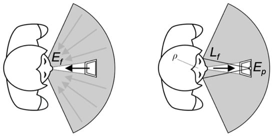
Figure 1.
Illuminance measurement geometry with mobile devices. The face illuminance (Ef) is affected by light from the central and surrounding peripheral visual field (left). Part of the light is reflected (depending on face reflectance, ⍴), and the resulting luminance of the face (Lf) determines the illuminance (EP) present at the camera CCD plane (right).
Knowing the face luminance, and assuming that skin can be approximated as a cosine reflector (Lambertian surface), we can calculate the face illuminance, Ef (Figure 1 left) as []:
where ρ represents the spectral reflectance of the face.
Finally, combining Equations (1)–(3) gives:
where the constant k′ includes all values that are considered constant for a particular device and face combination. The remaining values in Equation (4) are usually chosen automatically by the camera’s auto-exposure system based on the scene. Of all these values, the one that varies the most in response to a change in lighting conditions is the luma (grey level) of the pixels in the area in the image, which includes the face. Because the value k′ for each device and face combination is unknown, a calibration was necessary for each device/subject pairing to convert camera pixel luma values (Ym) to face illuminance (Ef).
2.2. Calibration
The ambient light sensor included in the device itself can be used to calibrate the system for each face and obtain the coefficient k′. The light that reaches the light sensor E0f is initially measured by situating the sensor in proximity to the subject’s eyes (Figure 2 left), facing forwards. Next, the device is restored to its natural orientation, facing the user at a comfortable distance (Figure 2 right) and a calibration illuminance, E0P is determined from the CCD of the device camera (Figure 2 right). The average value Ym is obtained from the area around the eyes in the image of the face captured by the front camera of the device. The exposure system of the camera adjusts the exposure time, ISO value, and the f/# automatically when taking the image. With this calibration approach, using the light sensor to calibrate the camera images, all the values in Equation (4) are known except the constant k′ which is computed and subsequently can be applied to any other image captured when the device is used under any other illumination conditions for the same face–device combination.
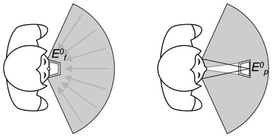
Figure 2.
Device calibration method. The light sensor of the device is placed near the eyes and facing forward to measure illuminance of the face (Ef) (left). The device is then placed at a typical viewing distance in front of the eye (30 cm) and the illuminance calculated at the camera CCD is measured (right).
The proposed methodology was evaluated by using two mobile devices: Samsun S6 Edge Plus (smartphone) and Samsung Galaxy Tab S2 (tablet). Firstly, the illuminance values measured by the ambient light sensors were examined to know the limitation of the methodology proposed due to the changes in the estimation of the k′ value during the calibration procedure with the ambient light distribution. To provide a measure of the angular sensitivity of the sensors, illuminance measurements under three light sources with different spatial distributions of light were tested and compared with those obtained with a standard light meter (Konica Minolta Sensing T-10A) that incorporates a wide field cosine-weighted sensor. This test provides a measure of the angular sensitivity of the device sensors relative to that of the illuminance meter, which includes an integrating dome. Secondly, device camera calibration was performed in several face–device combinations with subjects with different skin reflectance to confirm the veracity of Equation (4).
2.3. Angular Selectivity of Device Ambient Light Sensors
Three light sources representing the full range of angular selectivity were examined: (1) Wide-angle homogeneous source-a modified perimeter (Haag Streit Octopus 900, Switzerland) which emitted an approximately spatially homogeneous light over a full hemi-field (2π sr). Dome illuminance was adjusted in 400 lux increments over the range from 0 to 9000 lux. The lux meter and the devices with ambient light sensors were placed at the centre of the hemisphere facing the central fixation target inside the dome. (2) Small angular source-a high power (500 W) incandescent light, which subtended an angle of less than 2° from the position of the light sensors, which were pointed directly at the light source. The room lights were turned off, and light coming from secondary reflections in the room was minimized by cloaking the instruments in black cloth. Illumination values were measured over a range from 3 to 4000 lux. (3) Indoors office environment—An array of incandescent lights and controllable office ceiling lighting (range 80 to 700 lux)—was used to illuminate an office containing a desk. The rest of the office was illuminated by reflected and scattered light and directly from a standard set of ceiling light fixtures. The light sensors were not illuminated directly by the light sources, but pointed directly at the desk containing a laptop and documents. Diffuse reflections from the office walls, desks, and light emitted from a computer screen contributed to the illuminance measured by the light sensors.
2.4. Measures of Face Illuminance Using the Camera
A Samsung S6 Edge Plus smartphone camera was placed 30 cm from the face, a typical handheld viewing distance [], with the face approximately centered in the camera field of view. Camera calibration was achieved using a known face illuminance of 52 lux. Because Equation (4) depends on the reflectance of the face, the experiment was carried out on four subjects: one African (a 30-year-old native of Ghana), one East Asian (42-year-old from China), and two Caucasians (33-year-old from Poland and 51-year-old from Spain) in addition to two artificial faces of mannequins with different skin tones (dark and light skin) and hair color (Figure 3).
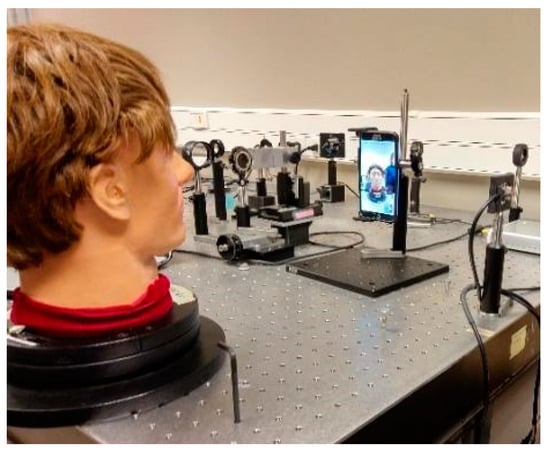
Figure 3.
Facial illuminance being measured for a mannequin using a Samsung S6 Edge Plus smartphone camera.
3. Results
Device light sensor calibrations revealed three key findings. First, sensor response is highly linear, with all but one least square linear fit to the data having R2 values in excess of 0.99. In all three environments, the sensor of the tablet reported higher values than the smart-phone (e.g., slopes of 0.70 vs. 0.52 with the hemispheric light source). The slopes below 1 for the wide field stimulus (Figure 4a), and the slopes > 1 for the small field stimulus (Figure 4b) reveal a narrower angular weighting for the detectors in each device compared to the wide field cosine weighting reported for the illuminance meter. Such narrower weighting will be more appropriate for visual field integration since the human monocular visual field is smaller than 2π sr due to restrictions of the brow, nose, and retina. For simplicity, we included the values of the slopes and the regression coefficients of the linear fitting lines of Figure 4a–c in Table 1. Results obtained under an office illumination environment with both devices (Figure 4c) indicate that the illuminance can be measure within a relative error lower than 25%.
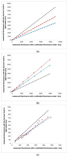
Figure 4.
Comparison of illuminance measured by Galaxy Tab S2 tablet (red circles) and the Samsung S6 + Smartphone (blue triangles) ambient light sensors to those measured with calibrated illuminance meter (Konica Minolta Sensing T-10A). (a) Wide angle homogeneous source; (b) Small angular source; (c) Office environment. The dashed black line represents the line Y = X.

Table 1.
Slope values and regression coefficients with each device in each of the conditions a table.
Face illuminance was computed from camera pixel values by applying Equation (4) to the average pixel value obtained from the camera images surrounding the eyes are compared to those obtained from the smart-phone light sensor (Figure 5). The two faces with darker skin are expected to reveal lower estimates because of reduced skin reflectance. Table 2 shows the values of the fitting lines to the data in Figure 5.
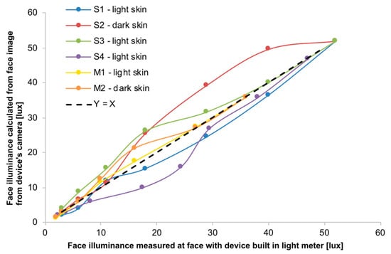
Figure 5.
Facial illuminance calculated after the methodology proposed with the Samsung S6 Edge Plus smartphone camera when using the phone a regular way, as in Figure 2-right (Y-axis) is plotted against illuminance measurements made with the phone’s on the face with the light meter facing the position where the phone is regularly used, as in Figure 2-left (X-axis).
Table 2.
Slope values and regression coefficients corresponding to the regression fit lines of Figure 5.
4. Discussion
The goal of this project was to assess the feasibility of using the already available smart phone cameras to monitor the general lighting levels experienced by children who might be at risk of developing myopia. Although many smart phones include a light sensor, when the device is being used, the light sensor faces toward the user and thus captures the light traveling in the opposite direction to the light that creates the retinal image. However, the forward-facing camera captures an image of the face, which is itself illuminated by the same general light sources that create the retinal image (those stimuli within the visual field). Therefore, smart phone cameras offer a convenient way to assess visually relevant environmental light exposure of the device user.
Our approach to assess the feasibility of using these cameras employed a calibrated illuminance meter to evaluate the smart phone built in light sensor (Figure 4), which revealed that in typical room situation, the inbuilt light sensor provided illuminance measures closely matching those of the calibrated illuminance meter. This result is encouraging in that it enables the smart phone light meter to be employed as a way to calibrate the camera for light measurements (see method of calibration, Figure 2), and the results (Figure 5) indicate accurate estimates of face illuminance can be obtained using the camera, and thus can be obtained in real-time over large durations once this initial calibration has been completed. Errors in face illuminance measures made with the camera are relatively small (mean error = 27%) and skin reflectance also has a relatively minor impact. The small magnitude of these errors is insignificant in the broad context of assessing the overall light levels experienced by children, which will vary by more than 1000 times when moving from outside on a bright sunny day to a dimly lit room at home.
Calibration of the built-in light sensor showed an underestimation of about 50% when a homogeneous illumination source was used that extended over a solid angle of 2π sr (Figure 4a) and an overestimation of about 80% when the illuminant was a small angle source in an otherwise dark field (Figure 4b). These inconsistencies between the device light sensor and the lux meter measurements reflect a combination of gain/sensitivity of the sensors as well as the angular selectivity of the sensors, which depend on their optical design. Sensors in smartphones have been reported to assess light levels over approximately 70° [], being maximal in the normal direction to the detector and decreasing with eccentricity []. Such angular selectivity is well designed to assess the visually relevant light levels as long as the sensor is located at or near the eye and directed away from the face.
5. Conclusions
The two main conclusions of the study are:
- (1)
- Illuminance resulting from the light sensors included in the smartphones is highly linear, and reveals a narrower spatial weighting than a full-hemifield lux meter.
- (2)
- It is possible to use a smartphone camera to measure the face illuminance in real-time with an accuracy around 80% once a one-time calibration has been performed using the devices in-built light sensor.
If the results can be extrapolated to the rest of devices (which typically used similar cameras and light sensors), the method proposed may give continuous reading (or at least at the speed of the video rate of the device) of the face illumination of the user, as long as the electronic device is being used and the subject is looking at it. Such technology implemented in a software (app) working in the background of the device can be useful to obtain objective data of the illumination received by the subject while the user is using the device naturally. Thus, it can be used as a tool to control myopia progression given the large time that the children and adults spend daily using their electronic devices [] under relatively low lighting conditions, usually indoors.
6. Patents
Patent pending: Bradley, A.; Jaskulski, M.; Lopez-Gil, N. A Computer-Implemented Method and System for Preventing Sight Deterioration Caused by Prolonged Use of Electronic Visual Displays in Low-Light Conditions. WO2019/166238A1, 2019.
Author Contributions
Conceptualization, M.J. and N.L.-G.; Data curation, A.B., M.J. and N.L.-G.; Formal analysis, R.M.S.-C., A.B., M.J. and N.L.-G.; Investigation, R.M.S.-C., A.B., M.J. and N.L.-G.; Methodology, A.B. and N.L.-G.; Project administration, N.L.-G.; Resources, A.B.; Software, M.J.; Supervision, A.B., M.J. and N.L.-G.; Validation, A.B., M.J. and N.L.-G.; Visualization, R.M.S.-C., A.B., M.J. and N.L.-G.; Writing—original draft, R.M.S.-C. and N.L.-G.; Writing—review & editing, R.M.S.-C., A.B., M.J. and N.L.-G. All authors have read and agreed to the published version of the manuscript.
Funding
This research received no external funding.
Institutional Review Board Statement
Not applicable.
Informed Consent Statement
Not applicable.
Data Availability Statement
Not applicable.
Conflicts of Interest
R. M. Salmerón-Campillo declares no conflict of interest. A. Bradley, M. Jaskulski, and N. López-Gil patent pending.
References
- Morgan, I.G.; Ohno-Matsui, K.; Saw, S.-M. Myopia. Lancet 2012, 379, 1739–1748. [Google Scholar] [CrossRef]
- Sun, J.; Zhou, J.; Zhao, P.; Lian, J.; Zhu, H.; Zhou, Y.; Sun, Y.; Wang, Y.; Zhao, L.-Q.; Wei, Y.; et al. High Prevalence of Myopia and High Myopia in 5060 Chinese University Students in Shanghai. Investig. Ophthalmol. Vis. Sci. 2012, 53, 7504–7509. [Google Scholar] [CrossRef] [Green Version]
- Jung, S.-K.; Lee, J.H.; Kakizaki, H.; Jee, D. Prevalence of Myopia and its Association with Body Stature and Educational Level in 19-Year-Old Male Conscripts in Seoul, South Korea. Investig. Ophthalmol. Vis. Sci. 2012, 53, 5579–5583. [Google Scholar] [CrossRef] [Green Version]
- Ng, S.W.; Popkin, B.M. Time use and physical activity: A shift away from movement across the globe. Obes. Rev. 2012, 13, 659–680. [Google Scholar] [CrossRef] [PubMed] [Green Version]
- Ip, J.M.; Rose, K.A.; Morgan, I.G.; Burlutsky, G.; Mitchell, P. Myopia and the Urban Environment: Findings in a Sample of 12-Year-Old Australian School Children. Investig. Ophthalmol. Vis. Sci. 2008, 49, 3858–3863. [Google Scholar] [CrossRef] [Green Version]
- Joo, J.; Sang, Y. Exploring Koreans’ smartphone usage: An integrated model of the technology acceptance model and uses and gratifications theory. Comput. Hum. Behav. 2013, 29, 2512–2518. [Google Scholar] [CrossRef]
- Ichhpujani, P.; Singh, R.B.; Foulsham, W.; Thakur, S.; Lamba, A.S. Visual implications of digital device usage in school children: A cross-sectional study. BMC Ophthalmol. 2019, 19, 76. [Google Scholar] [CrossRef]
- Wu, P.-C.; Tsai, C.-L.; Wu, H.-L.; Yang, Y.-H.; Kuo, H.-K. Outdoor Activity during Class Recess Reduces Myopia Onset and Progression in School Children. Ophthalmology 2013, 120, 1080–1085. [Google Scholar] [CrossRef] [PubMed]
- Morgan, I.; Rose, K. How genetic is school myopia? Prog. Retin. Eye Res. 2005, 24, 1–38. [Google Scholar] [CrossRef] [PubMed]
- Wu, P.-C.; Chen, C.-T.; Lin, K.-K.; Sun, C.-C.; Kuo, C.-N.; Huang, H.-M.; Poon, L.Y.-C.; Yang, M.-L.; Chen, C.-Y.; Huang, J.-C.; et al. Myopia Prevention and Outdoor Light Intensity in a School-Based Cluster Randomized Trial. Ophthalmology 2018, 125, 1239–1250. [Google Scholar] [CrossRef] [PubMed] [Green Version]
- Flitcroft, D. The complex interactions of retinal, optical and environmental factors in myopia aetiology. Prog. Retin. Eye Res. 2012, 31, 622–660. [Google Scholar] [CrossRef]
- Ashby, R.; Ohlendorf, A.; Schaeffel, F. The Effect of Ambient Illuminance on the Development of Deprivation Myopia in Chicks. Investig. Ophthalmol. Vis. Sci. 2009, 50, 5348–5354. [Google Scholar] [CrossRef] [Green Version]
- Cohen, Y.; Belkin, M.; Yehezkel, O.; Solomon, A.S.; Polat, U. Dependency between light intensity and refractive development under light–dark cycles. Exp. Eye Res. 2011, 92, 40–46. [Google Scholar] [CrossRef]
- Smith, E.L.; Hung, L.-F.; Huang, J. Protective Effects of High Ambient Lighting on the Development of Form-Deprivation Myopia in Rhesus Monkeys. Investig. Ophthalmol. Vis. Sci. 2012, 53, 421–428. [Google Scholar] [CrossRef] [PubMed] [Green Version]
- Gwiazda, J.; Deng, L.; Manny, R.E.; Norton, T.T. Seasonal Variations in the Progression of Myopia in Children Enrolled in the Correction of Myopia Evaluation Trial. Investig. Ophthalmol. Vis. Sci. 2014, 55, 752–758. [Google Scholar] [CrossRef]
- Mccrann, S.; Loughman, J.; Butler, J.S.; Paudel, N.; Flitcroft, D.I. Smartphone use as a possible risk factor for myopia. Clin. Exp. Optom. 2021, 104, 35–41. [Google Scholar] [CrossRef]
- Read, S.; Collins, M.; Vincent, S. Light Exposure and Physical Activity in Myopic and Emmetropic Children. Optom. Vis. Sci. 2014, 91, 330–341. [Google Scholar] [CrossRef] [PubMed] [Green Version]
- Read, S.A.; Collins, M.; Vincent, S. Light Exposure and Eye Growth in Childhood. Investig. Ophthalmol. Vis. Sci. 2015, 56, 6779–6787. [Google Scholar] [CrossRef]
- Read, S. Ocular and Environmental Factors Associated with Eye Growth in Childhood. Optom. Vis. Sci. 2016, 93, 1031–1041. [Google Scholar] [CrossRef] [Green Version]
- Verkicharla, P.K.; Ramamurthy, D.; Nguyen, Q.D.; Zhang, X.; Pu, S.-H.; Malhotra, R.; Ostbye, T.; Lamoureux, E.L.; Saw, S.-M. Development of the FitSight Fitness Tracker to Increase Time Outdoors to Prevent Myopia. Transl. Vis. Sci. Technol. 2017, 6, 20. [Google Scholar] [CrossRef] [PubMed]
- Dharani, R.; Lee, C.F.; Theng, Z.X.; Drury, V.B.; Ngo, C.; Sandar, M.; Wong, T.Y.; Finkelstein, E.A.; Saw, S.M. Comparison of measurements of time outdoors and light levels as risk factors for myopia in young Singapore children. Eye 2012, 26, 911–918. [Google Scholar] [CrossRef] [Green Version]
- Wen, L.; Cao, Y.; Cheng, Q.; Li, X.; Pan, L.; Li, L.; Zhu, H.; Lan, W.; Yang, Z. Objectively measured near work, outdoor exposure and myopia in children. Br. J. Ophthalmol. 2020, 104, 1542–1547. [Google Scholar] [CrossRef] [PubMed] [Green Version]
- Pajic, B.; Zakharov, P.; Pajic-Eggspuehler, B.; Cvejic, Z. User Friendliness of a Wearable Visual Behavior Monitor for Cataract and Refractive Surgery. Appl. Sci. 2020, 10, 2190. [Google Scholar] [CrossRef] [Green Version]
- Rose, K.A.; Morgan, I.G.; Ip, J.; Kifley, A.; Huynh, S.; Smith, W.; Mitchell, P. Outdoor Activity Reduces the Prevalence of Myopia in Children. Ophthalmology 2008, 115, 1279–1285. [Google Scholar] [CrossRef]
- Rideout, V.M.B. Common Sense Media. Available online: https://www.commonsense.org (accessed on 21 May 2021).
- Do, T.-H.; Yoo, M. Performance Analysis of Visible Light Communication Using CMOS Sensors. Sensors 2016, 16, 309. [Google Scholar] [CrossRef] [PubMed]
- Bradley, A.; Jaskulski, M.T.; Lopez-Gil, N. A Computer-Implemented Method and System for Preventing Sight Deterioration Caused by Prolonged Use of Electronic Visual Displays in Low-Light Conditions. U.S. Patent 16/977,574, 3 February 2019. [Google Scholar]
- Hiscocks, P.D. Measuring Luminance with a Digital Camera; Syscomp Electronic Design Limited. 2011. Available online: https://scholar.google.com/scholar?hl=es-ES&q=Hiscocks+PD.+Measuring+luminance+with+a+digital+camera.+Technical+report%2C+Syscomp+Electronic+Design+Limited%2C+2014 (accessed on 10 July 2021).
- Texas Instruments. OPT3007 Ultra-Thin Ambient Light Sensor; Texas Instruments: Dallas, TX, USA, 2017. [Google Scholar]
- Ferraro, V.; Mele, M.; Marinelli, V. Sky luminance measurements and comparisons with calculation models. J. Atmos. Sol. Terr. Phys. 2011, 73, 1780–1789. [Google Scholar] [CrossRef]
- Sarwar, M.; Soomro, T.R. Impact of Smartphone’s on Society. Eur. J. Sci. Res. 2013, 98, 216–226. [Google Scholar]
Publisher’s Note: MDPI stays neutral with regard to jurisdictional claims in published maps and institutional affiliations. |
© 2021 by the authors. Licensee MDPI, Basel, Switzerland. This article is an open access article distributed under the terms and conditions of the Creative Commons Attribution (CC BY) license (https://creativecommons.org/licenses/by/4.0/).