Article

Determination of the Loading of a Flat Rack Container during Operating Modes

1
Department of Cars and Carriage Facilities, State University of Infrastructure and Technologies, Kyrylivska 9, 04071 Kyiv, Ukraine
2
Department of Transport and Handling Machines, Faculty of Mechanical Engineering, University of Zilina, Univerzitna 1, 01026 Zilina, Slovakia
3
Department of Structural Mechanics and Hydraulics, Ukrainian State University of Railway Transport, Feuerbach Square 7, 61050 Kharkiv, Ukraine
4
Department of Wagon Engineering and Product Quality, Ukrainian State University of Railway Transport, Feuerbach Square 7, 61050 Kharkiv, Ukraine
*
Author to whom correspondence should be addressed.
Appl. Sci. 2021, 11(16), 7623; https://doi.org/10.3390/app11167623
Submission received: 12 July 2021 / Revised: 10 August 2021 / Accepted: 18 August 2021 / Published: 19 August 2021
(This article belongs to the Section Robotics and Automation)

Abstract

:
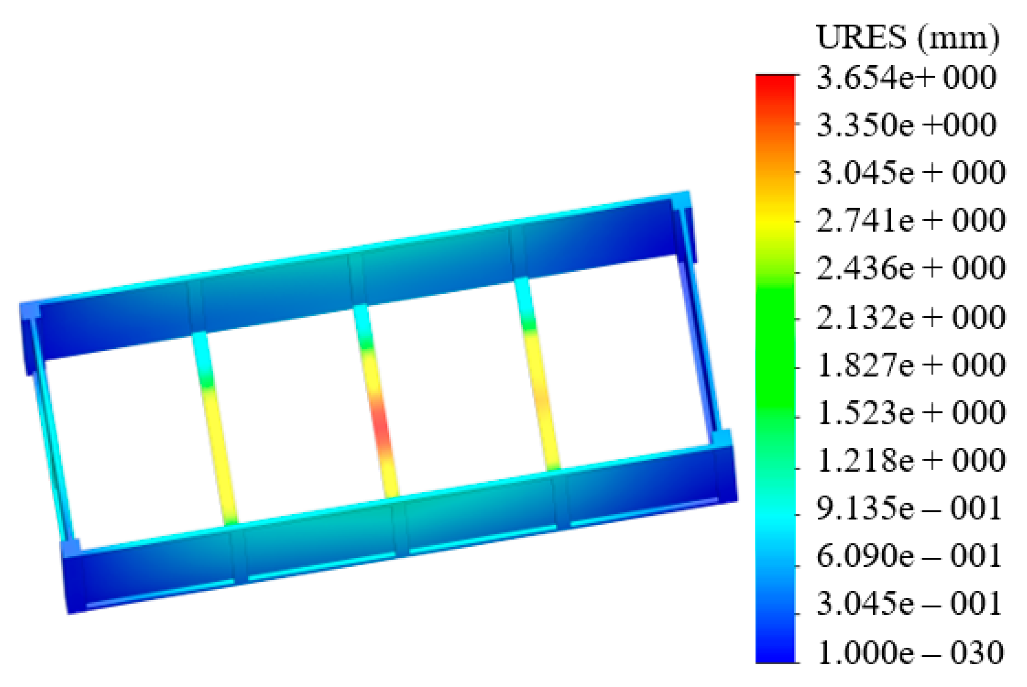
This research deals with determination of the loading of an open container during operating modes. The special feature of this container is its convex walls. This engineering solution increases the useful capacity of a container by 8% in comparison to that of the prototype. The elastic elements in the bearing structure of a container were introduced to decrease the dynamic loads. The dynamic loads in the vertical plane were dumped by means of the dry friction forces between the components of the cross bearers of the container’s base. The dynamic loads in the longitudinal plane were dumped by means of the dry friction forces between the horizontal parts of fittings and fixed lashing components. This study presents the modelling of the dynamic loading of a container in a vertical plane. The dynamic loads of a container in the longitudinal plane were determined with a mathematical model. The authors determined the basic strength characteristics of the bearing structure of a container; and found that the maximum stresses to a container were about 200 MPa, concentrated near the front fittings. The maximum displacements were recorded in the cross bearers of the base and amounted to about 4 mm.

1. Introduction

The strategic plan for development of railway transport and maintenance of its leading position in the transportation market requires introduction of combined transport systems [1,2]. The most popular of them is container transportation. It is explained by the mobility of a container, which can be transported by different transport means. This combined transportation is constantly developing and modernizing. At present, there are a great variety of containers; they can be closed and open (Flat Rack) for freight, which does not require protection from weather conditions.
Rail transportation of containers is presumably conducted by flat cars. They are fastened on the frame with fixed lashing components and fittings. During operation, the technological gaps between containers and flat cars cause higher stresses leading to damage of the fixed lashing components and fittings. For example, on the basis of the data collected by Ukrzaliznytsia, the authors determined the amount of damage the fixed lashing components of flat cars suffer in operation [3]. The results of the research are given in Figure 1.
The main damage to the fitting stops of platform wagons is cracking in the construction, as well as their fractures. The most common damage to containers is cracking in fittings and deformations in supporting constructions.
Figure 1 demonstrates that 2013 saw the maximum amount of these defects. The period was marked by an intensive container transportation. In the period 2014–2015, there was a slight decline in container transportation of goods by rail. In this connection, there is also less damage to the fitting stops of wagons–platforms. From 2015 to 2019 the intensification of container transportation on flat wagons has slightly increased and, as a result, an increase in their damage can be traced.
This requires off-schedule repairs and additional expenditures for maintenance of transport means. Therefore, there is a need for improved container structures. This can improve the efficiency of rail transportation and maintain its leading position in the transportation market.

2. Analysis of Literature Data and Problem Statement

Some prospects of introduction of rail cars with detachable bodies of higher freight capacity are studied in [4]. The suggested new structure of a freight car with the detachable body can increase the efficiency of railway transport. A choice of lashing devices for fixation of containers and detachable bodies on the rail flat cars is described in [5]. The proposed lashing device can provide a higher reliability against the action of longitudinal and transverse loads, and overturning moment. It should be noted that these structural solutions do not decrease the dynamic loads of a detachable body (container) during rail transportation in a flat car.
The research on introduction of new multimodal transport equipment—changeable bodies in China—is presented in [6]. It included the prospects of functioning and requirements for changeable bodies in operation. However, the study does not include safety requirements for changeable bodies in operation.
The analysis of strength characteristics of a 40-foot container structure during operating loads is presented in [7]. The calculation was made in Abaqus/CAE v.6.1 software. The authors present the requirements for safe operation of this container type.
The strength of fixation of a container to the frame of an Rgs wagon was studied in [8]. The authors found the optimal diagram for fixation of a container to the car, which provides its stability during operating modes.
However, these studies do not describe measures for decreasing the dynamic loads and improving the strength of the bearing structure of a container transported by flat cars.
The dynamic loads of a container in operating modes are defined in [9,10]. The authors described techniques of how to decrease the dynamic loads of a container with elastic, viscous and elastic–viscous elements between the container and the flat car. Here, the dynamic loads of a container decrease in the longitudinal plane. However, the issue of how to decrease the dynamic loads of a container in the vertical plane was not studied.
Some special features of the dynamic loads of containers located on flat cars during shunting impacts are described in [11]. The research was conducted with mathematic modelling and confirmed with computer modelling. The results of calculation were used for working out the safety requirements regarding flat cars and containers in operation.
However, the study does not provide measures for decreasing the dynamic loads of containers during the most unfavourable loading modes.
Features of the use of simplified methods for measuring the stress–strain state of a body container of variable volume, the proposed loading scheme and test method for container bodies for lateral and longitudinal skews are provided in [12].
Determination of the stress–strain state of the body container of variable volume is carried out in the publication [13]. The calculation was performed in the environment of the ANSYS software package. To verify the adequacy of the results, experimental studies were performed on the lateral skew of the container at low loads.
Measures to improve the load-bearing construction of the container to reduce its dynamic load under operating conditions in these works are not provided.
The study of the stress–strain state of the container body when lifted by a crane and dragged is carried out in [14]. The theoretical determination of strength indicators is carried out in the software package AWP WinMachine. The experimental strength study was performed using the method of electric strain measurement.
The peculiarities of creating a container for the transportation of fruits and vegetables are covered in [15]. The article presents the requirements for the container body, proposes its design, and calculates the strength by the finite element method.
It is important to note that the study of the dynamic load of containers in these works is not carried out, and the determination of strength is carried out taking into account the normative values of loads. In addition, the authors have not proposed measures to improve the efficiency of operation of the proposed container designs.
The study of dynamic loads acting on a tank container placed on a flat wagon during a shunting collision is provided in [16]. The interaction of the tank container with the platform wagon was simulated by an elastic-dissipative connection at a longitudinal load from a 2200–2800 kN striking wagon. The choice of the parameters of the shock-absorbing device was carried out for the case when the gaps between the fittings and the fitting stops are maximum, and there is no movement of the fluid cargo. The given model takes into account the presence of three degrees of freedom of the container. The maximum value of the longitudinal impact force that can act on a flat car with a load placed on it, including containers, during a shunting collision, is 3.5 MN [17,18].
Therefore, in order to obtain an updated value of the accelerations acting on the container in operation, it is necessary to conduct additional research.
Determination of the dynamic loading of the container under operating conditions was carried out in [19]. The obtained values of dynamic loads were taken into account when calculating the container strength in the environment of the Ansys software package.
The study of the supporting structure strength of the container under operating conditions of loading is carried out in the publication [20]. The paper analyzes the effect of the density of the finite element model on the accuracy of calculating the stress–strain state of the container and also conducts field studies of its strength under shock loads.
It is important to say that measures to improve the load-bearing constructions of containers in order to reduce their dynamic loading have not been proposed in the works under consideration.
Paper [21] analyzes the requirements for the design of containers and ISO standards, the identified problems and inconsistencies between the rules and standards, as well as their impact on the safety of containers operation.
A review of the main problems of the railway vehicles operation related to traffic safety is carried out in [22]. The main criteria used in assessing the safety of vehicle traffic in accordance with the standards of different countries are considered.
At the same time, the issues of improving containers to reduce their dynamic loading and ensure operational safety are not considered in these works.
The design features of a container made of composite material are covered in [23]. The given results of calculations for the strength of the container under the main operating conditions of the load. However, the work does not provide studies of the dynamic loading of the container under the main operating conditions.
The work [24], where a method of eco-design of structural elements of vehicles is proposed, is of scientific interest. The features of the application of this method are highlighted. At the same time, the work does not pay attention to the issues of increasing the efficiency of the operation of vehicles, including containers, taking into account the application of the proposed method.
In work [25], the design loads on containers under operating conditions are determined. The requirements for the safe operation of containers are indicated.
The specifics of designing containers for the transportation of long cargo are covered in [26]. An example of calculating the strength of a container when loading it with round pipes is given. The calculation results confirmed the feasibility of the structural solutions adopted in the design.
Determination of the dynamic loading of the flat car with containers is carried out in [27]. A model is proposed that allows one to take into account the movement of the container under the longitudinal loading of the flat car. The refined values of the loads acting on the supporting structure of the flat car and containers during a shunting collision have been determined. At the same time, these works do not indicate measures to reduce the loading of containers under the most unfavourable conditions.
Analysis of the literature [4,5,6,7,8,9,10,11,12,13,14,15,16,17,18,19,20,21,22,23,24,25,26,27] allows us to conclude that insufficient attention has been paid to the improvement of the load-bearing structures of containers in order to reduce the dynamic loading. This raises the need for research in this direction, which will increase the efficiency of the operation of container transportation by rail.

3. The Purpose and Tasks of the Research

The purpose of the research is the development of structural improvements for a container and determination of the loading during operating modes.
To achieve this purpose, the following tasks were set:
  • to suggest measures for improving the bearing structure of a container;
  • to determine the dynamic loading of a container in the vertical plane;
  • to determine the dynamic loading of a container in the longitudinal plane; and
  • to determine the strength characteristics of the bearing structure of a flat car.

4. Improvements in the Bearing Structure of a Container

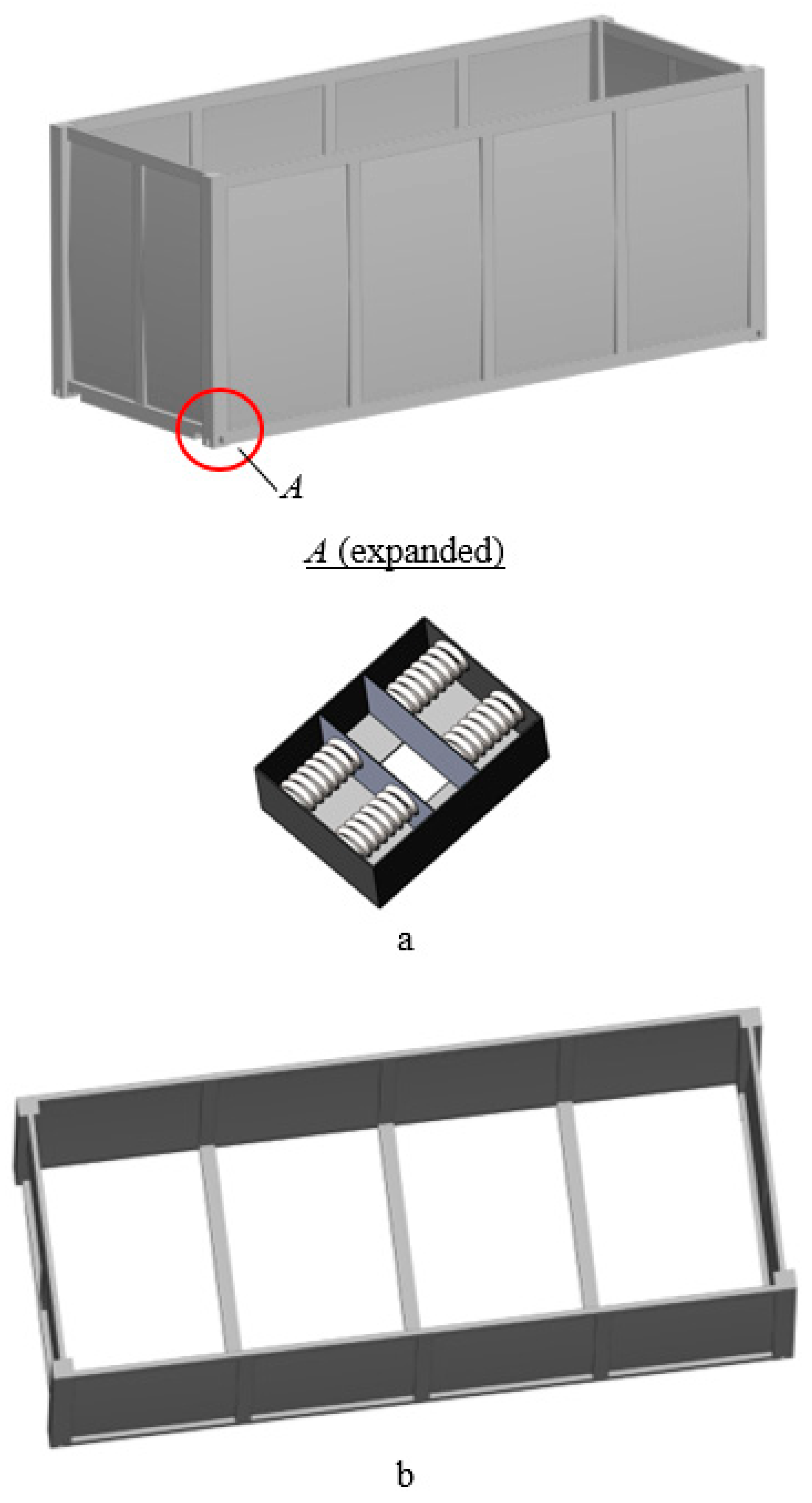
A higher efficiency of a container can be achieved by the structural solution of convex end and side walls (Figure 2).
This sidewall geometry can increase the useful capacity of a container by 8% in comparison to that of the prototype. The volume of the new container design was determined using classical geometric constraints. At the same time, the construction of the container geometry was carried out in the SolidWorks Simulation software package. After that, the area, which forms the convex wall cladding, was determined. Knowing the basic geometric parameters of the container, its volume was calculated and compared with the volume of a typical design.
The deflection of the side and end walls was technologically determined i.e., the dimensions of the container were not changed.
The dynamic loads of a container caused by the technological gaps between fixed lashing components and fittings in rail transportation can be decreased by introducing elastic elements in the fittings (Figure 2a). The dynamic loads can be decreased by means of the dry friction forces between the horizontal parts of fittings and fixed lashing components.
The dynamic loads in the vertical plane were decreased with elastic elements mounted in the cross bearers of the frame (Figure 3).
The dynamic loads in the vertical plane were decreased by means of the dry friction forces. These forces exerted between the U-profile beam and the horizontal sheet over the elastic elements.

5. Determination of the Dynamic Loading of a Container in the Vertical Plane

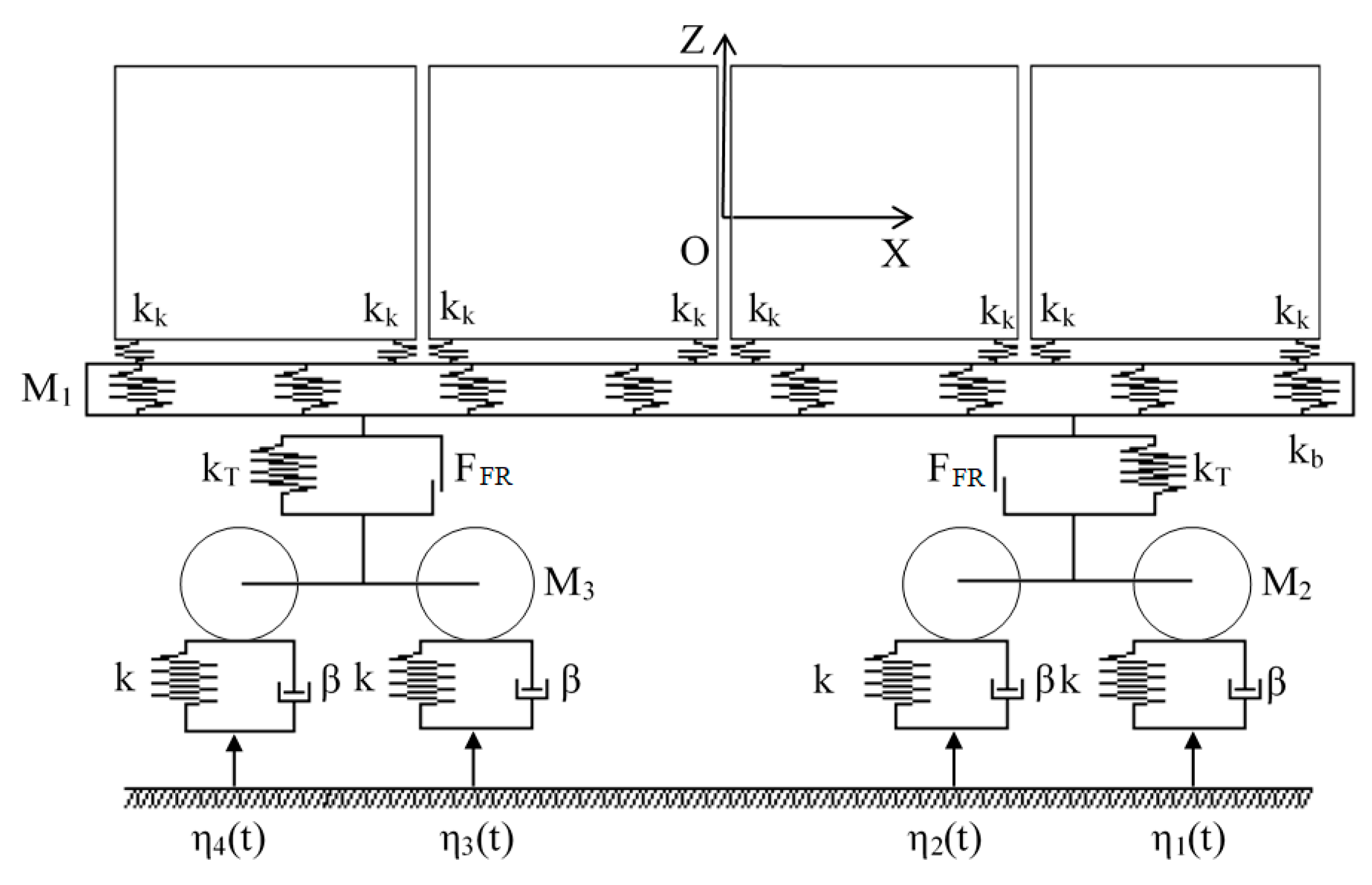
The dynamic loading of a container was determined with mathematic modelling. The design diagram is presented in Figure 4. The research took into account that the flat car was loaded with four containers. The link between the containers and the frame of a flat car was modeled as elastic.
The differential equations of motion of a flat car loaded with containers look like:
M 1 q ¨ 1 + C 1 , 1 q 1 + C 1 , 2 q 2 + C 1 , 3 q 3 = F F R ( s i g n ( δ ˙ 1 ) + s i g n ( δ ˙ 2 ) ) i = 1 4 F z ,
M 2 q ¨ 2 + C 2 , 1 q 1 + C 2 , 2 q 2 + B 2 , 2 q ˙ 2 = F F R s i g n ( δ ˙ 1 ) + k ( η 1 + η 2 ) + β ( η ˙ 1 + η ˙ 2 ) ,
M 3 q ¨ 3 + C 3 , 1 q 1 + C 3 , 3 q 3 + B 3 , 3 q ˙ 3 = F F R s i g n ( δ ˙ 2 ) + k ( η 3 + η 4 ) + β ( η ˙ 3 + η ˙ 4 ) ,
M 4 q ¨ 4 = F z M 4 g ,   F z = k k ( q 1 q 4 ) ,
where M1—mass of the bearing structure of a flat car; M2, M3—mass of the first and second bogies facing the engine, accordingly; M4—container mass; Cij—elasticity characteristics of the elements of the oscillation system determined by the rigidity coefficients of the springs kT; kb—rigidity of the elastic elements in the side beams of the frame; kk—rigidity of the elastic linkage which models the interaction between a container and a flat car; Bij—dissipation function; a—half-base of a bogie; k—track rigidity; β—damping coefficient; FFR—absolute friction force in a spring group; δi—deformation of elastic elements of spring suspension; and η(t)—track irregularity.
The study assumed that a flat car loaded with containers moved on the elastic viscous track [28,29,30].
Differential Equations (1)–(4) were solved in the MathCad software [31,32,33] and was determined as
F ( t , y ) = [ y 2 y 4 y 6 y 8 F F R ( s i g n ( δ ˙ 1 ) + s i g n ( δ ˙ 2 ) ) i = 1 4 F z C 1 , 1 y 1 C 1 , 2 y 3 C 1 , 3 y 5 M 1 F F R s i g n ( δ ˙ 1 ) + k ( η 1 + η 2 ) + β ( η ˙ 1 + η ˙ 2 ) C 2 , 1 y 1 C 2 , 2 y 3 B 2 , 2 y 4 M 2 F F R s i g n ( δ ˙ 2 ) + k ( η 3 + η 4 ) + β ( η ˙ 3 + η ˙ 4 ) C 3 , 1 y 1 C 3 , 3 y 5 B 3 , 3 y 6 M 3 F z M 4 g M 4 ] , Z = r k f i x e d ( Y 0 , t n , t k , n , F ) ,
where Y0—vector with the initial conditions, tn and tk—values determining the initial and final integration variable, n’—fixed number of stages, Q—symbolic vector [34,35].
Here
y 1 = q 1 , y 3 = q 3 , y 5 = q 5 , y 7 = q 7 ,
y 2 = y ˙ 1 , y 4 = y ˙ 3 , y 6 = y ˙ 5 , y 8 = y ˙ 7 .
The initial displacements and speeds were taken equal to zero [36,37,38]. The results of the calculation are shown in Figure 5.

6. Determination of the Dynamic Loading of a Container in the Longitudinal Plane

The accelerations to a container located on the flat car in the longitudinal plane were determined with the mathematical model (Equation (6)). The design diagram is presented in Figure 6. The model included the displacements in the bearing structure of a flat car loaded with containers when a load of 3.5 MN acted to the rear fixed component of an automatic coupler [17,18]. Moreover, the model included the dry friction force emerging between the fixed lashing components and fittings, and the rigidity of the elastic elements mounted in the fittings of containers.
{ M F L g w q ¨ 1 = P l i = 1 n ( F F R s i g n ( q ˙ 1 q ˙ 2 ) + C e ( q 1 q 2 ) ) , M k q ¨ 2 = ( F F R s i g n ( q ˙ 1 q ˙ 2 ) + C e ( q 1 q 2 ) ) ,
where MFLgw—gross weight of a flat car; Pl—longitudinal impact force to the automatic coupler; n—number of containers on a flat car; FFR—friction force between fixed lashing components and fittings; Mk—container mass; Ce—rigidity of elastic elements in the fittings of a container; q1, q2—coordinates determining the displacements of a flat car and a container relative to the longitudinal axle.
The system of differential Equation (6) was solved in the MathCad software complex as
Q ( t , y ) = | y 3 y 4 P l i = 1 n ( F F R s i g n ( y 3 y 4 ) + C e ( y 1 y 2 ) ) M F L g w F F R s i g n ( y 3 y 4 ) + C e ( y 1 y 2 ) M k | Z = r k f i x e d ( Y 0 , t n , t k , n , Q )
where
y 1 = q 1 , y 2 = q 2 ,
y 3 = y ˙ 1 , y 4 = y ˙ 2 ,
The initial displacements and the speeds were taken equal to zero [36,37,38]. The results of the calculation are shown in Figure 7.
The maximum accelerations to the constrainer were about 2.0 m/s2. The acceleration value obtained was 20% lower than the acceleration to the standard container (2.5 m/s2).

7. Determination of the Strength Characteristics of the Bearing Structure of a Container

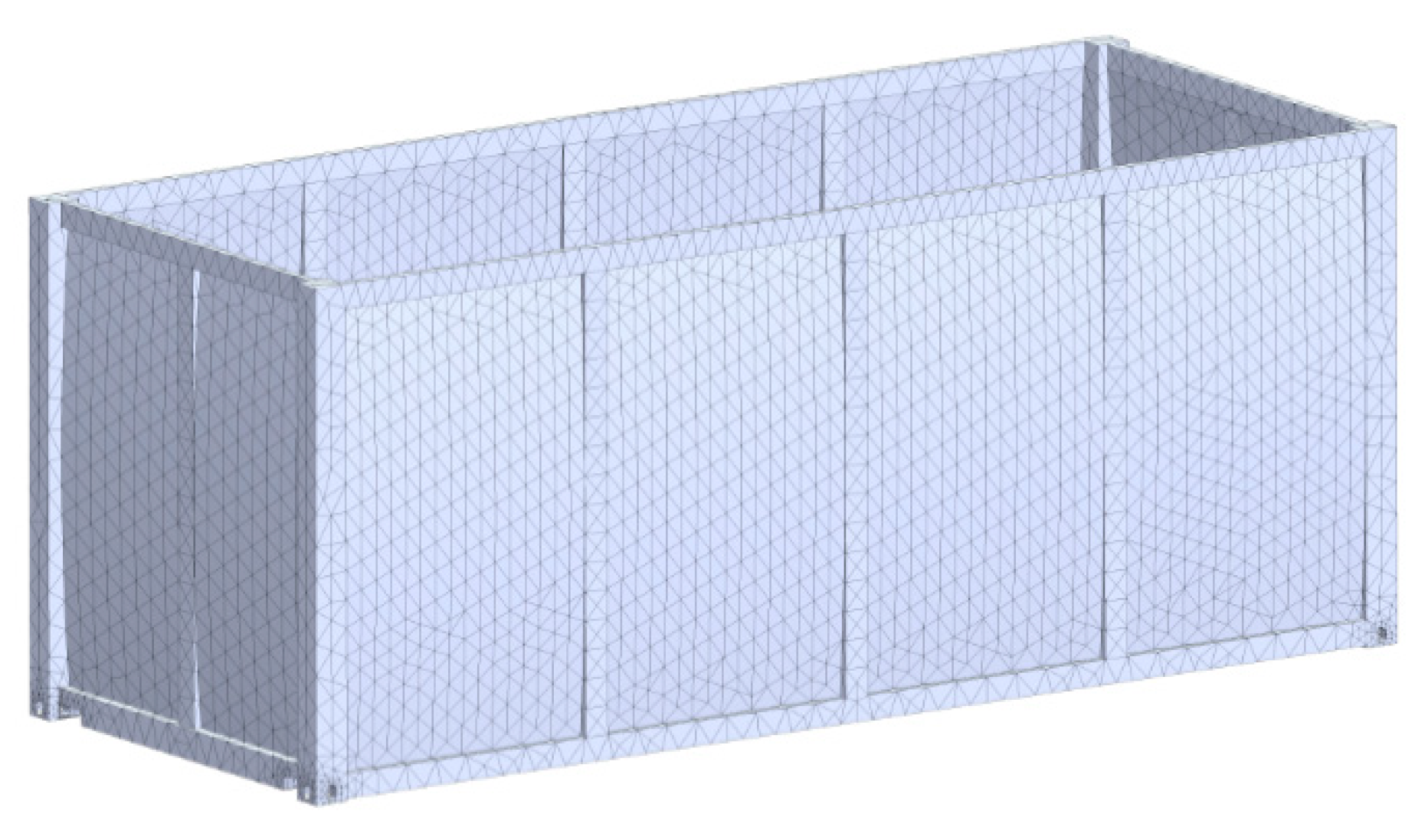
The strength of the bearing structure of a container was determined with the finite element method in the SolidWorks Simulation software [39,40]. The finite element model (FEM) was built with isoparametric tetrahedrons [41,42]. The number of nodes in the mash was 14,606 and the number of elements was 47,787. The maximum element size was 120 mm and the minimum element size was 24.0 mm. The maximum side ratio was 8330.9; the percentage of elements with a side ratio of less than three and greater than ten were 5.88 and 84.9, respectively. The FEM of a container is shown in Figure 8.
The design diagram included the following forces to the container: vertical force Pv, pressure of the bulk freight Pb, and reaction Pr in the fittings to the action of the longitudinal force to the rear fixed element of an automatic coupler (Figure 9).
The container was secured in the areas of support on the frame of a flat car. Steel 09C2Cu was taken as the structural material.
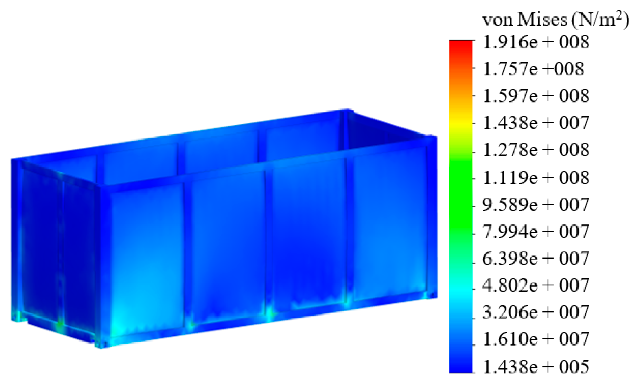
It was found that the maximum stresses to a container were about 200 MPa; they were concentrated in the areas near the front fittings (Figure 10). The maximum displacements were recorded in the cross bearers of the base and amounted to about 4 mm (Figure 11). The maximum deformations were 1.908 × 10⁻³. Thus, the strength of a container was provided [17,18,43].

8. Discussion of the Loading Values of a Container Obtained during Operating Modes

The authors suggested the use of containers with convex walls to achieve a higher operational efficiency. The dynamic loads of a container in the longitudinal plane were decreased by means of elastic elements. The dynamic loading of a container in the vertical plane in the cross bearer of the base was also reduced with application of elastic elements.
Application of the improvements suggested can increase the useful capacity of a container by 8% in comparison to that of the prototype.
The authors studied the dynamic loading of a container in the vertical plane. The maximum accelerations on the constrainer were about 2.0 m/s2 (Figure 5). The acceleration value obtained was 20% lower than the acceleration to the standard container. It should be noted that the mathematical model built did not include the angular displacements of a container in the vertical plane, it described only the translational motion.
The results of determination of the dynamic loading of a container in the longitudinal plane demonstrated that the maximum accelerations amounted to about 40.0 m/s2 (Figure 7). The acceleration value obtained was 65% lower than the acceleration to the standard container. The mathematical model built included the longitudinal displacements of a flat car loaded with containers.
The strength characteristics of a container were defined with the strength calculation by means of the finite element method in the SolidWorks Simulation software. The maximum stresses to a container were about 200 MPa; they were concentrated near the front fittings and the maximum displacements were about 4 mm (Figure 11). Thus, the strength of a container was provided.
Further research in the field will include the experimental determination of the loading of a container; it can be fulfilled with the application of the strain measurement method.
This research can be used in the development of innovative structures of containers, which can increase the efficiency of railway operations.

9. Conclusions

1. The study deals with the measures for improving the bearing structure of a container. The special feature of this container is its convex walls. The loading of the container structure can be decreased by means of elastic elements in fittings and cross bearers.
2. The authors determined the dynamic loading of a container in the vertical plane. The research was based on a flat car loaded with four containers. The linkage between the containers and the frame was taken as elastic. The maximum accelerations on a constrainer were about 2.0 m/s2. The acceleration value obtained was 20% lower than the acceleration to the standard container.
3. The study deals with determination of the dynamic loading of a container in the longitudinal plane. The maximum accelerations to a constrainer were about 40.0 m/s2. The acceleration value obtained was 65% lower than the acceleration to the standard container.
4. The authors determined the strength characteristics of the bearing structure of a container. The calculation was carried out with the finite element method. It was found that the maximum stresses to a container were about 200 MPa; they were concentrated near the front fittings. The maximum displacements were recorded in the cross bearers of the base and amounted to about 4 mm. The maximum deformations were 1.908 × 10³. Thus, the strength of a container was provided.

Author Contributions

Conceptualization, O.F., A.L. and J.G.; methodology, O.F. and A.L.; software, A.L.; validation, A.L., J.G. and G.V.; investigation, O.F., A.L. and K.K.; resources, O.F., A.L. and K.K.; writing—original draft preparation, O.F., A.L. and K.K.; writing—review and editing, J.G. and G.V.; visualization, O.F., A.L. and K.K.; supervision, J.G. and G.V. All authors have read and agreed to the published version of the manuscript.

Funding

This publication was issued thanks to supporting the Cultural and Educational Grant Agency of the Ministry of Education of the Slovak Republic in the project No. KEGA 036ŽU-4/2021: Implementation of modern methods of computer and experimental analysis of properties of vehicle components in the education of future vehicle designers. This research was also conducted within the research project for young researchers “Innovative approaches in designing resource-saving railway structures with refined dynamic loading and functional-adaptive flash-concepts”, and funded by the 2020 State Budget of Ukraine.

Institutional Review Board Statement

Not applicable.

Informed Consent Statement

Not applicable.

Data Availability Statement

Not applicable.

Conflicts of Interest

The authors declare no conflict of interest.

References

  1. Šťastniak, P.; Kurčík, P.; Pavlík, A. Design of a new railway wagon for intermodal transport with the adaptable loading platform. MATEC Web Conf. 2018, 235, 00030. [Google Scholar] [CrossRef]
  2. Dižo, J.; Steišunas, S.; Blatnický, M. Simulation analysis of the effects of a rail vehicle running with wheel flat. Manuf. Technol. 2016, 16, 889–896. [Google Scholar] [CrossRef]
  3. Fomin, O.; Kulbovskiy, I.; Sorochinska, E.; Sapronova, S.; Bambura, O. Experimental confirmation of the theory of implementation of the coupled design of center girder of the hopper wagons for iron ore pellets. Eastern-Eur. J. Enterp. Technol. 2017, 5/1, 11–19. [Google Scholar] [CrossRef] [Green Version]
  4. Boronenko, Y.P.; Dauksha, A.S. The prospects of railroad cars with increased carrying swap bodies implementation. Proc. Petersburg Transp. Univ. 2017, 3, 437–451. (In Russian) [Google Scholar]
  5. Boronenko, Y.P.; Dauksha, A.S. The prospects of railroad cars with increased carrying swap bodies implementation. Transp. Russ. Federation. J. Sci. Pract. Econ. 2017, 3, 29–32. (In Russian) [Google Scholar]
  6. Chuanjin, O.U.; Bingtao, L.I. Research and application of new multimodal transport equipment-swap bodies in China. E3S WebofConferences 2020, 145, 02001. [Google Scholar] [CrossRef] [Green Version]
  7. Rzeczycki, A.; Wisnicki, B. Strength analysis of shipping container floor with gooseneck tunnel under heavy cargo load. Solid State Phenom. 2016, 252, 81–90. [Google Scholar] [CrossRef]
  8. Berescu, C.; Fratila, C.; Axinte, T.; Diaconu, M.; Cojocaru, R. The mechanism’s study of fixing a container on a freight wagon type Rgs. IOP Conf. Ser. Mater. Sci. Eng. 2020, 916, 012010. [Google Scholar] [CrossRef]
  9. Lovska, A.; Fomin, O.; Píštěk, V.; Kučera, P. Dynamic load modelling with in combined transport trains during transportationon a railway ferry. Appl. Sci. 2020, 10, 5710. [Google Scholar] [CrossRef]
  10. Fomin, O.; Lovska, A.; Píštek, V.; Kucera, P. Dynamic load effect on the transportation safety of tank containers as part of combined trains on railway ferries. Vibroeng. Procedia 2019, 29, 124–129. [Google Scholar] [CrossRef]
  11. Lovska, A.; Fomin, O. A new fastener to ensure the reliability of a passenger coach car body on a railway ferry. Acta Polytech. 2020, 60, 478–485. [Google Scholar] [CrossRef]
  12. Mishuta, D.V. Simplified methods for measuring the stress-strain state of a container body of variable volume. Instrum. Methods Meas. 2012, 2, 100–103. (In Russian) [Google Scholar]
  13. Mishuta, D.V.; Algin, V.B.; Mikhailov, V.G. Assessment of the stress-strain state of a container body of variable volume. Bull. Belarusian-Russ. Univ. 2012, 4, 61–68. (In Russian) [Google Scholar]
  14. Eremin, V.; Semennikova, L. Investigation of the stress-strain state of a container body using the AWM WinMachine software package. CAD Graph. 2004, 7, 23–28. (In Russian) [Google Scholar]
  15. Ibragimov, N.N.; Rakhimov, R.V.; Khadzhimukhamedova, M.A. Development of a container design for transportation of fruits and vegetables. Young Sci. 2015, 21, 168–173. (In Russian) [Google Scholar]
  16. Bogomaz, G.I.; Mekhov, D.D.; Pilipchenko, O.P.; Chernomashentseva, Y.G. Loading of tank containers located on a railway flat wagon when impact into an automatic coupler. Dyn. Control Motion Mech. Syst. 1992, 1, 87–95. (In Russian) [Google Scholar]
  17. DSTU 7598:2014. Freight Wagons. General Requirements for Calculations and Design of New and Modernized Wagons of 1520 mm Track (Non-Self-Propelled); UkrNDNTS: Kiev, Ukraine, 2015; 162p. (In Ukrainian) [Google Scholar]
  18. GOST 33211-2014. Freight Wagons. Requirements for Strength and Dynamic Properties; FGUP “STANDARTINFORM”: Moskow, Russia, 2016; 54p. (In Russian) [Google Scholar]
  19. Tiernan, S.; Fahy, M. Dynamic fea modelling of iso tank containers. J. Mater. Process. Technol. 2002, 124, 126–132. [Google Scholar] [CrossRef]
  20. Makeiev, S.V.; Builenkov, P.M. Features of Calculating the Stress-Strain State of a Tank-Container Taking into Account the Actual Loading in Operation. SCIENCE-EDUCATION-PRODUCTION: Experience and Development Prospects: A Collection of Materials from the XIV International Scientific and Technical Conference Dedicated to the Memory of Doctor of Technical Sciences; Zudov, E.G., Ed.; Gorgo-Metallurgical Production. Mechanical Engineering and Metalworking; NTI (Branch) UrFU: Nizhny Tagil, Russia, 2018; Volume 1, pp. 174–184. [Google Scholar]
  21. Martin, S.; Martin, J.; Lai, P. International container design regulations and ISO standards: Are they fit for purpose? Marit. Policy Manag. 2018. [Google Scholar] [CrossRef]
  22. Kardas-Cinal, E. Selected problems in railway vehicle dynamics related to running safety. Arch. Transp. 2014, 31, 37–45. [Google Scholar] [CrossRef]
  23. Yildiz, T. Design and Analysis of a Lightweight Composite Shipping Container Made of Carbon Fiber Laminates. Logistics 2019, 3, 18. [Google Scholar] [CrossRef] [Green Version]
  24. Andriankaja, H.; Vallet, F.; Le Duigou, J.; Eynard, B. A method to ecodesign structural parts in the transport sector based on product life cycle management. J. Clean. Prod. 2015, 94, 165–176. [Google Scholar] [CrossRef]
  25. Acanfora, M.; Montewka, J.; Hinz, T.; Matusiak, J. On the estimation of the design loads on container stacks due to excessive acceleration in adverse weather conditions. Mar. Struct. 2017, 53, 105–123. [Google Scholar] [CrossRef]
  26. Panasenko, N.N.; Yakovlev, P.V. Design of containers for sea transportation of long pipes. Bull. Astrakhan State Tech. Univ. Ser. Mar. Eng. Technol. 2014, 3, 97–107. (In Russian) [Google Scholar]
  27. Nikitchenko, A.; Artiukh, V.; Shevchenko, D.; Prakash, R. Evaluation of Interaction Between Flat Car and Container at Dynamic Coupling of Flat Cars. MATEC Web Conf. 2016, 73, 04008. [Google Scholar] [CrossRef] [Green Version]
  28. Fomin, O.; Lovska, A. Establishing patterns in determining the dynamics and strength of a covered freight car, which exhausted its resource. East. Eur. J. Enterp. Technol. 2020, 6, 21–29. [Google Scholar]
  29. Fomin, O. Modern requirements to carrying systems of railway general-purpose gondola cars. Sci. Tech. J. Metall. Min. Ind. 2014, 5, 31–43. [Google Scholar]
  30. Goolak, S.; Gubarevych, O.; Yermolenko, E.; Slobodyanyuk, M.; Gorobchenko, O. Mathematical Modeling of an Induction Motor for Vehicles. East. Eur. J. Enterp. Technol. 2020, 2, 25–34. [Google Scholar] [CrossRef]
  31. Dyomin, Y.V.; Chernyak, G.Y. Fundamentals of Car Dynamics; QUETT: Kyiv, Ukraine, 2019. (In Ukrainian) [Google Scholar]
  32. Kiryanov, D.V. Mathcad 13; BHV. Petersburg: Saint Petersburg, Russia, 2006. (In Russian) [Google Scholar]
  33. Dyakonov, V. MATHCAD 8/2000: A Special Reference Book; Piter: Saint Petersburg, Russia, 2000. (In Russian) [Google Scholar]
  34. Lovska, A. Simulation of Loads on the Carrying Structure of an Articulated Flat Car in Combined Transportation. Int. J. Eng. Technol. 2018, 7, 140–146. [Google Scholar] [CrossRef] [Green Version]
  35. Kondratiev, A.; Gaidachuk, V.; Nabokina, T.; Tsaritsynskyi, A. New possibilities in creating of effective composite size-stable honeycomb structures designed for space purposes. Adv. Intell. Syst. Comput. 2020, 1113, 45–59. [Google Scholar]
  36. Kelrykh, M.; Fomin, O. Perspective directions of planning carrying systems of gondolas. Metall. Min. Ind. 2014, 6, 64–67. [Google Scholar]
  37. Lovska, A.A. Peculiarities of computer modeling of strength of body bearing construction of gondola car during transportation by ferry-bridge. Metall. Min. Ind. 2015, 1, 49–54. [Google Scholar]
  38. Kuric, I.; Gorobchenko, O.; Litikova, O.; Gritsuk, I.; Mateichyk, V.; Bulgakov, M.; Klackova, I. Research of vehicle control informative functioning capacity. Pap. Presented IOP Conf. Ser. Mater. Sci. Eng. 2020, 776, 012036. [Google Scholar] [CrossRef]
  39. Alyamovsky, A.A. SolidWorks/COSMOSWorks 2006–2007. In Engineering Analysis by the Finite Element Method; DMK Press: Moscow, Russia, 2007. (In Russian) [Google Scholar]
  40. Alyamovsky, A.A. COSMOSWorks. In Fundamentals of Structural Strength Analysis in the SolidWorks Environment; DMK Press: Moscow, Russia, 2010. (In Russian) [Google Scholar]
  41. Vatulia, G.; Komagorova, S.; Pavliuchenkov, M. Optimization of the truss beam. Verification of the calculation results. MATEC Web Conf. 2018, 230, 02037. [Google Scholar] [CrossRef]
  42. Vatulia, G.L.; Lobiak, O.V.; Deryzemlia, S.V.; Verevicheva, M.A.; Orel, Y.F. Rationalization of cross-sections of the composite reinforced concrete span structure of bridges with a monolithic reinforced concrete roadway slab. IOP Conf. Ser. Mater. Sci. Eng. 2019, 664, 012014. [Google Scholar] [CrossRef]
  43. EN 12663–2. Railway Applications—Structural Requirements of Railway Vehicle Bodies—Part 2: Freight Wagons. B.; BDS: Sofia, Bulgaria, 2010; 54p. [Google Scholar]
Figure 1. Amount of damage in fixed lashing components of the flat cars in operation.
Applsci 11 07623 g001
Figure 2. Flat Rack container with convex walls: (a) side view; (b) top view.
Applsci 11 07623 g002
Figure 3. Location of elastic elements in the cross bearers of a container.
Applsci 11 07623 g003
Figure 4. Design diagram of the bearing structure of a flat car loaded with containers.
Applsci 11 07623 g004
Figure 5. Acceleration acting on the container in the vertical plane.
Applsci 11 07623 g005
Figure 6. Design diagram of a flat car loaded with containers.
Applsci 11 07623 g006
Figure 7. Accelerations to a container in the longitudinal plane.
Applsci 11 07623 g007
Figure 8. FEM of a container.
Applsci 11 07623 g008
Figure 9. Design diagram of a container.
Applsci 11 07623 g009
Figure 10. Stress strain state of a container.
Applsci 11 07623 g010
Figure 11. Displacements in the units of a container.
Applsci 11 07623 g011
Publisher’s Note: MDPI stays neutral with regard to jurisdictional claims in published maps and institutional affiliations.