Article

PFC Single-Phase AC/DC Boost Converters: Bridge, Semi-Bridgeless, and Bridgeless Topologies

by
José R. Ortiz-Castrillón
1,
Gabriel Eduardo Mejía-Ruíz
2,
Nicolás Muñoz-Galeano
1,
Jesús M. López-Lezama
1,* and
Sergio D. Saldarriaga-Zuluaga
3
1
Research Group on Efficient Energy Management (GIMEL), Department of Electrical Engineering, Universidad de Antioquia (UdeA), Medellín 050010, Colombia
2
Electrical Engineering-Power Systems, National Autonomous University of Mexico, Mexico City 04510, Mexico
3
Facultad de Ingenieria, Departamento de Eléctrica, Institución Universitaria Pascual Bravo, Calle 73 No. 73A-226, Medellín 050036, Colombia
*
Author to whom correspondence should be addressed.
Appl. Sci. 2021, 11(16), 7651; https://doi.org/10.3390/app11167651
Submission received: 16 July 2021 / Revised: 17 August 2021 / Accepted: 18 August 2021 / Published: 20 August 2021

Abstract

:
Power Factor Correction (PFC) single-phase AC/DC converters are used in several power electronics applications as full wave control rectifiers improving power quality and providing high standards of efficiency. Many papers dealing with the description or use of such topologies have been published in recent years; however, a review that describes and organizes their specific details has not been reported in the technical literature. Therefore, this paper presents an extensive review of PFC single-phase AC/DC converters operating with the Boost converter topology for low and medium voltage as well as and power appliances. A categorization of bridge, semi-bridgeless, and bridgeless, in accordance with the construction characteristics, was carried out in order to unify the technical terminology. Benefits and disadvantages are described and analyzed in detail. Furthermore, a comparison performance in terms of PFC, Total Harmonic Distortion (THD), power capacity, electromagnetic compatibility (EMC), number of elements, and efficiency is included.

1. Introduction

Conventional diode rectifiers convert an AC supply into a DC voltage draw pulsed current from the supply network, which increases electromagnetic interference (EMI), reduces energy efficiency, and decreases the capacity of the network to carry electrical power [1,2]. An alternative for overcoming these issues in power systems is the use of Controlled Boost Power (CBP) converters instead of conventional diode rectifiers [3,4,5,6]. CBP converters implement the Power Factor Correction (PFC) technique that consists of controlling the AC current demanded from the network in such a way that AC current is sinusoidal and in phase with the voltage of the supply network and, at the same time, they perform DC voltage regulation in their output. Basically, CBP converters behave as a resistive load for the electrical network, improving the power quality and overall efficiency and also by helping comply with the harmonic regulation IEC 1000-3-2 [7,8,9,10,11]. Another important aspect is that CBP converters may also avoid the use of active power filters between the power network and loads, which yields a more economic and suitable solution in these kinds of applications [12,13]. The implementation of CBP converters contributes to the better use of power networks avoiding reactive and harmonic components of power flow through the power system; consequently, energy losses are reduced in transmission and distribution lines, and the energy quality is improved. In general terms, the improvement of power quality by means of CBP converters not only for PF correction but also for EMI and T H D i reduction are issues that concern the users, distributors, and generators [14,15,16].
The implementation of CBP converters is still a research topic. Most of the research in this area focuses on control strategies and new topologies [2,17,18]. However, an organized document that permits to consult advantages and drawbacks of CBP converter topologies and their control strategies have not yet been reported in the technical literature. This review includes organized information useful in selection, design, and implementation stages of CBP converters.
As regards their applications, CBP converters are widely used in modern power converter suppliers for computers, data centers, servers, telecommunication equipment, and on-board electrical vehicle chargers [19,20,21]. High efficiency, high power density, low harmonic distortion, and high power factor are attributes that drive the innovation and evolution of this technology [1,17]. These attributes largely depend on the implemented circuit topology. Based on this feature, CBP converters can be classified into: Bridge Boost converter (BBC), Semi-Bridgeless Boost Converter (SBBC), and Bridgeless Boost converter (BLBC) whose main features are described below, while the main modifications of topologies reported in the scientific literature are explained in detail in the body of the work.
BBC topologies have been incorporated in recent years for powering DC loads due to their general simplicity. BBC allows for reaching low levels of T H D i and high PF. However, this topology exhibits the following comparative disadvantages when used in medium-high power applications: (1) BBC has at least three semiconductor devices in the path of currents from source to load which increases conduction losses; (2) BBC requires a switching frequency greater than 30 kHz to lower the T H D i below the IEC 1000-3-2 standard; (3) the inductor is located on the DC side requiring design considerations to avoid saturation of its core. BBC topology, in its conventional form, is only recommended for applications up to 1 kW [8,22,23]. The power consumed by the line bridge rectifier takes up to 30∼60% of the total losses in a large range in a BBC rectifier [23]. Some advances have been presented in the technical literature trying to solve these disadvantages. In [24], a control structure for the operation of BBC converters under variable switching frequency was proposed. Switching frequency is modified for two reasons: (1) to reduce switching losses; in this case, frequency around the peak of the current signal is decreased; (2) to reduce T H D i during the current zero crossing; in this case, frequency is increased. It was found that T H D i is reduced; however, the current waveform is not fully sinusoidal causing T H D i to not meet IEC/EN 61000-3-2 (or IEC 1000-3-2) and IEEE Std. 519 [25]. In [26], EMI produced by BBC functioning was mitigated using a filter, being adequate for low power converters. BBC operation requires a closed-loop controller with a power filtering stage to simultaneously ensure EMI and T H D i reduction while keeping high PFC and regulating of DC voltage [27,28,29,30,31]. For these factors, a number of hardware changes for the BBC topology have been proposed by the scientific community which are explained in detail in this paper [4,32,33,34,35,36,37].
SBBC topologies allow for reducing conduction losses; basically, SBBC has less semiconductor devices in the path of the current from the source to the load compared to BBC topologies. However, this converter exhibits a significant amount of common mode noise in the input current, requiring additional components that increase the complexity of the circuit. The common mode problem is induced by the floating output ground, which is pulsating according to the switching frequency. In addition, this topology requires an additional inductor that increases the weight, size, and cost of the power converter. In this topology, EMI problems at the common coupling point can be reduced by adding diodes, capacitors, inductors, and also appropriate location of symmetrical switches for phase and neutral lines [38,39,40].
BLBC converters have an asymmetrical arrangement of their elements in the converter branches which mitigates reverse-recovery currents from diodes. It has no common mode interference problem because the output voltage is clamped to the input by diodes during each half-line cycle. Additionally, this topology has the potential capacity for bidirectional power conversion. Nevertheless, its inherent asymmetry increases the complexity of the controller and requires isolation in each driver of the branches [41,42,43].
For CBP converters, performance measures such as efficiency, number of components, PFC, T H D i , maximum operating power, and other features are highly dependent on the circuit topology. In recent years, researchers have reported a large number of CBP topologies that have received increased attention from the scientific community [17,27,28,35,37]. Some bibliographic reviews that have gathered information on the BBC, SBBC, and BLBC have recently been published [16,44]. However, these reviews neglect the analysis of interleaved converters and do not include any analysis regarding electromagnetic compatibility and power factor. In addition, review [16] was published in 2005, while review [44] was published in 2010; nonetheless, in the last decade, the scientific community has presented important advances in terms of new topologies, control systems, input filters, and power switches. This paper presents the CBP topologies and their modifications reported in the last fifteen years. In addition, according to the literature search, we found that CBP converters are called by different names by different authors; however, according to their topological structure, we categorized the converters into BBC, SBBC, and BLBC converters. Finally, this paper provides a comparative analysis that can be useful for researchers and developers to select the appropriate topology according to their application, showing their corresponding advantages and disadvantages and also giving recommendations.
This paper is structured as follows: Section 2, Section 3 and Section 4 are respectively focused on the categorization of BBC, SBBC, and BLBC converters. Section 5 corresponds to the summary of the topologies included in the paper, and a comparative study is made in terms of: control type, voltage level, power level, number of semiconductors, and number of inductors and capacitors that compose each topology; in this section, recommendations are given to assist designers and developers in the topology selection process according to their particular requirements. Finally, Section 6 concludes and highlights the most relevant aspects of the paper.

2. Categorization of Bridge Boost Converter Topologies

BBC topologies with PFC based on Boost converter are presented in this section. BBC converters are mainly composed of a full rectifier bridge; however, all BBC topologies presented in this section need a line EMI filter between the feeding source and the bridge to comply with international normatives regarding T H D i (lower than 6%), regardless of the control system [25]. Nevertheless, sizing of the EMI filter depends on the number of switches, control strategy, voltage level, power level, and paths to handle the converter currents.

2.1. BBC Topologies

Figure 1 shows the conventional BBC topology where ( v a c ) is the electrical grid or feeding source. The rectification is performed by means of the diode bridge ( D 1 , D 2 , D 3 and D 4 ) [16,30,32,33,45]. Inductor (L) and capacitor (C) interchange energy while diode (D) prevents reverse currents. Resistor (R) is the load that is feeding through a regulated voltage from the DC bus. Control structure is usually implemented by using a cascade PI structure for regulating the DC bus and also performing PFC.
The conventional BBC is the most common topology used in low voltage and power applications due to its reduced number of components. However, when medium and high voltage converters are required, power losses must be taken into account in the design process for obtaining a more accurate estimation of efficiency and gains of the system [28,46].
In [16,47], the authors showed the importance of soft switching for medium and high voltage and power applications of BBC. In [16], a review concerning soft switching techniques with snubber circuits to reduce power switching losses in BBCs was presented. This work analyzes four main aspects: (1) application for low voltage; (2) behavior in Discontinuous Conduction Mode (DCM) and Continuous Conduction Mode (CCM); (3) contrast between Zero Voltage Switching (ZVS), Zero Voltage Transition (ZVT), and Zero Current Switching (ZCS) techniques; and (4) comparison between MOSFET and IGBT switching technologies. It should be noted that there are switch technologies with better performance than conventional IGBTs and MOSFETs. These technologies include Gallium Nitride (GaN) switches and Silicon Carbide (SiC) MOSFET switches. GaN and SiC technologies can be used (recommended) in frequencies between 100 KHz and 200 KHz, so that GaN and SiC switches present better efficiency (lower losses) than conventional IGBTs and MOSFETs. More information concerning these switch technologies is available in [48,49,50]). In general terms, switching with ZVS or ZCS increases the switch useful life. Resonant BBC topology that operates with ZVS or ZCS can be implemented by adding an LC circuit to BBC conventional topology. Further details can be consulted in [51,52,53,54,55,56,57,58,59,60,61,62,63]. The aforementioned resonant LC circuit requires an additional switch (a second one) to introduce an inductor to the converter circuit for providing an additional path with zero impedance where the current and voltage do not strongly change their values.
The BBC converter is directly connected to the AC supply, so its diodes and power switches inject harmonics and produce noise; then, an EMI filter is required. The authors in [26] present a design of an EMI filter for a medium power BBC, where results show a reduction of the Common Mode (CM) and Differential Mode (DM) noise when high switching frequency is needed. The EMI filter with classical linear PID control can reduce T H D i to normative ranges; nevertheless, limitations of PID control (slow and tuning around of an operation point) can reduce its efficiency, increasing T H D i and causing poor dynamic performance when the converter operates out of its design range [64]; this can be solved with nonlinear controllers or PID hybrid control techniques [3,22,24,29,30,45,65,66,67,68]. For example, a modulation technique for the BBC that can operate in DCM or CCM, exhibiting a high P F and low T H D i over a wide range of input voltage and load is presented in [3,69].
The conventional BBC topology can be modified as it was proposed in [70]. Figure 2 shows the BBC with pseudo-continuous conduction mode where diode D 5 and switch Q 1 were added in parallel with L. This modification increases dynamic behavior in transients and reduces stress in L by current circulation. Nevertheless, the addition of two semiconductors introduces two issues: (1) the increasing of losses because of the addition of more elements and (2) a complex control strategy to control Q 1 . This converter modification presents low ripple in DCM and CCM operation for low power application. Another modification to this topology was presented in [71], where two capacitors and inductors were added between the feeding source and the rectifier bridge. This converter presents low T H D i and high efficiency with cascade PID control for low voltage and power application. Nevertheless, the additional components increase its implementation cost.
In conclusion, a BBC of conventional topology requires an intermediate filtering equipment for EMI mitigation together with a robust control strategy—this is in order to ensure a correct behavior in low and medium power applications [27,34,50,69,72,73,74,75]. In addition, SBBC of conventional topology are recommended instead of BBC in applications for medium and high power due to their low EMI [16].

2.2. Conventional Interleaved BBC

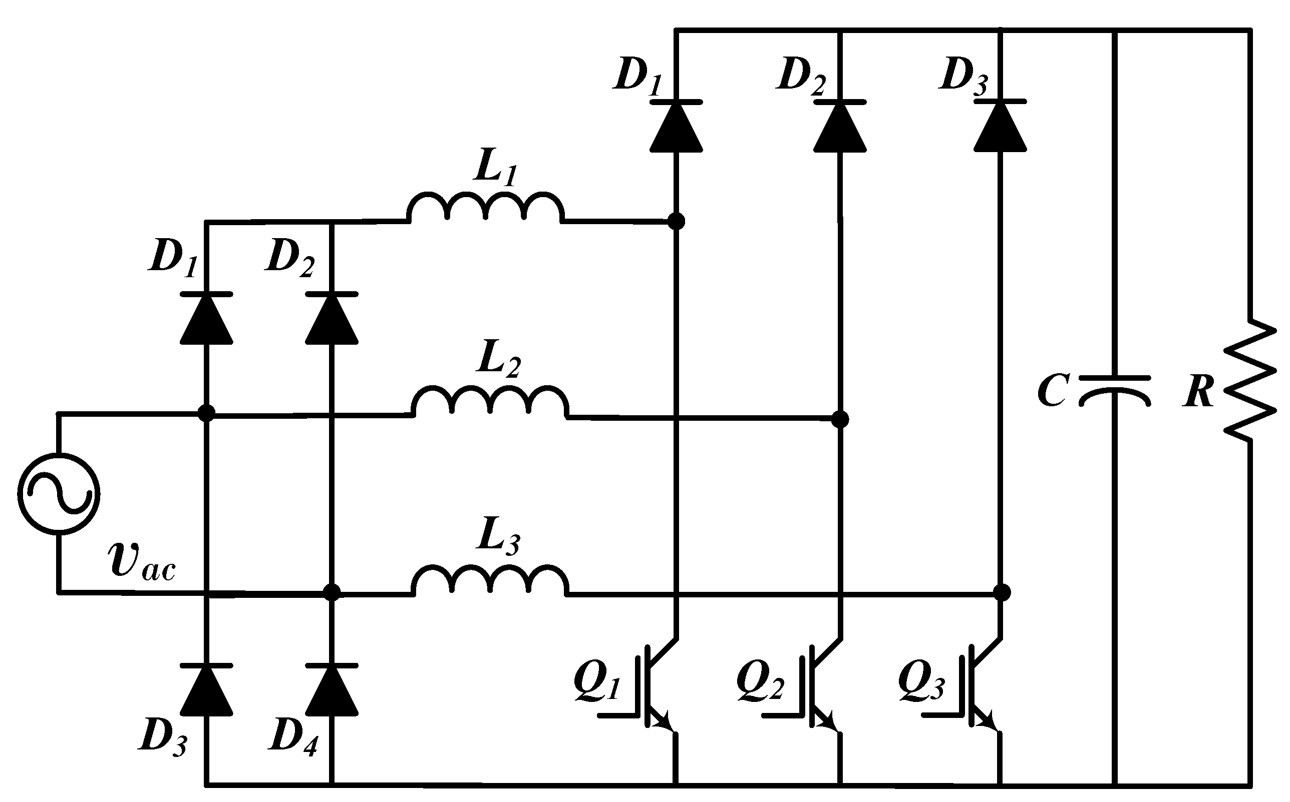
An interleaved BBC converter has several boost converters connected between the rectifier bridge and DC link capacitor for providing current levels, which improves power quality; consequenty, ripple current in input is reduced. In addition, the levels make it possible to reduce the size of inductors, diodes, and circuit switches since thermal stress is reduced. An interleaved BBC converter is recommended for regulating the DC voltage in medium voltage applications since it provides voltage levels in the DC link bus; however, it is not recommended for high voltage applications since power losses and EMI issues are high due to the rectifier bridge. In medium voltage, a robust filter is necessary (EMI filter with several stages) between the AC power supply and the converter; in addition, the use of resonant circuits is recommended for each level for providing soft switching which reduce losses [32,76,77,78]. Figure 3 corresponds to the interleaved BBC converter that is composed of two stages which is commonly implemented in industrial applications [10,28,79,80]. In [28,81,82], and it presented a methodology for the design of inductors, capacitors, diodes, and power switches. The authors also included the design of the EMI filter. Simulation and experimental results presented an efficiency of around 97% and a power factor up to 0.995.
The conventional Interleaved BBC with two states can be modified as it was presented in [7]. The authors proposed to move switches and inductors before the rectifier bridge. Simulation results presented T H D i into a normative range with classical PI control for applications in low voltage and power. In addition, operation in DCM and CCM was considered, obtaining an efficiency greater than 96%.

2.3. Conventional Hybrid Interleaved PFC Topology Based on a Boost Converter

An interleaved hybrid BBC topology with three levels was proposed in [31]; please see Figure 4. This converter may feature an efficiency around 97% when using a PI controller. The authors reported that T H D i normative is reached when an EMI filter is used. Basically, currents flow between the branches of the converter, allowing not only the reduction of the ripple current and but also the losses when compared with the interleaved converter of two levels; nonetheless, the addition of a third branch increases its cost. In general terms, this converter is suggested for medium voltage applications because of its low ripple and T H D i compared to the conventional BBC converter. In addition, this three-level topology is also recommended in low-voltage applications—this together with independent soft switching circuits considering an independent design control for each switch. The interleaved hybrid BBC topology complies with approximately the same function as the interleaved topology (with three states) presented in Section 2.2; then, the interleaved topology is recommended instead of the hybrid one considering that the hybrid is limited by three states.

2.4. Conventional PFC Topology with Bidirectional Switch

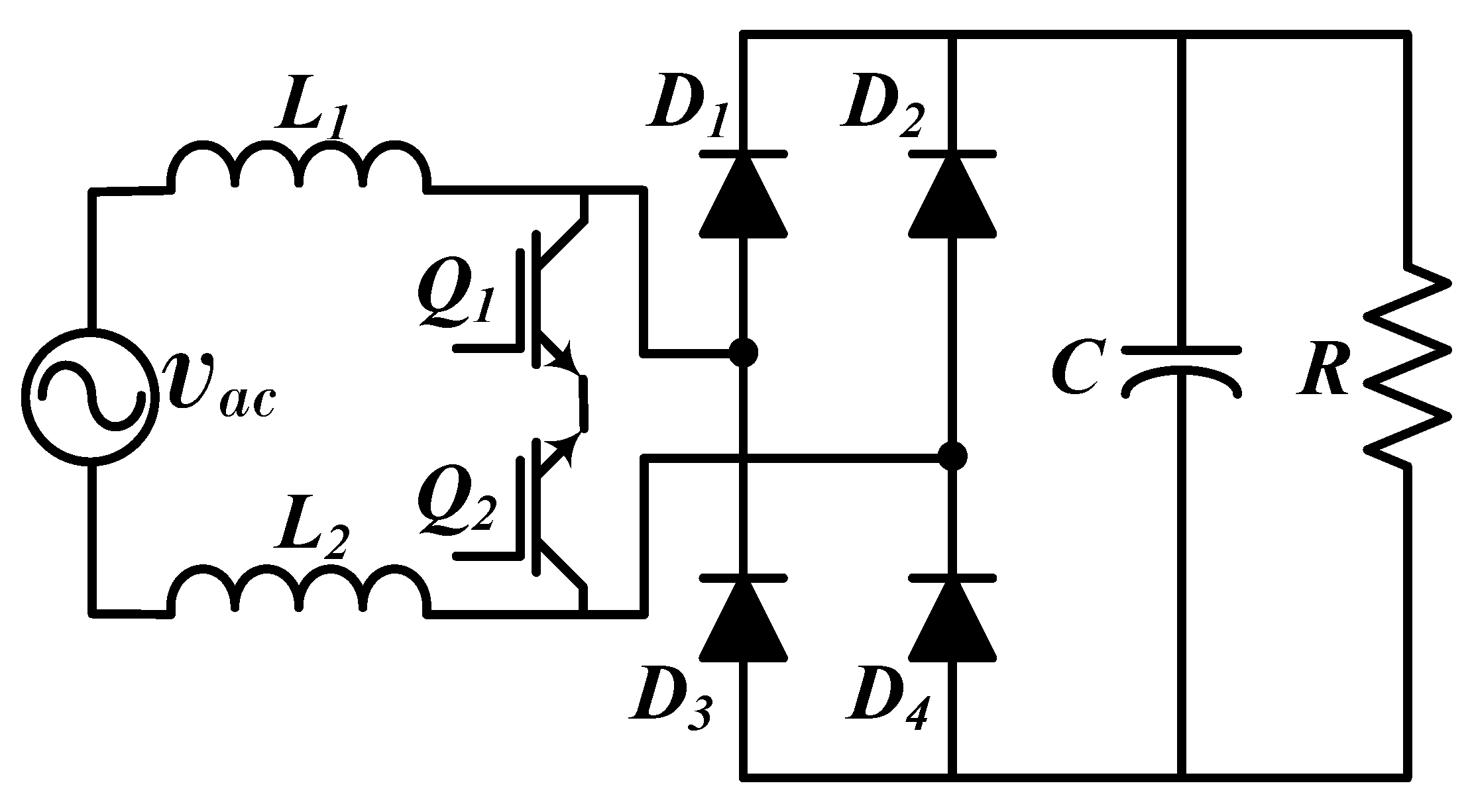
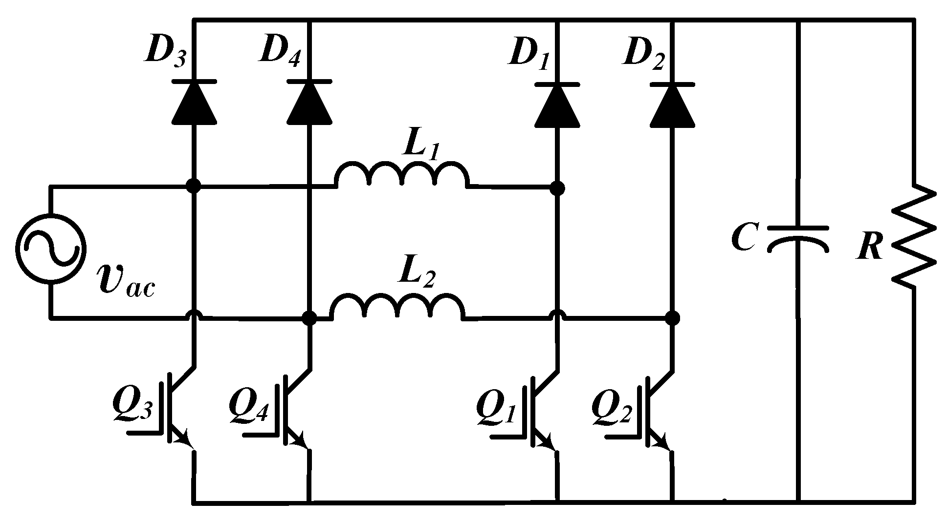
Figure 5 shows the BBC Conventional PFC Topology with Bidirectional Switch [37,83]. In this topology, inductors L 1 and L 2 ( L 1 = L 2 ) are used as coupling inductors, while the bidirectional switch composed of Q 1 and Q 2 is on the AC side of the converter. For an appropriate operation, D 1 and D 4 must be fast-recovery diodes. This topology permits the reduction of the common mode noise; however, an EMI filter in the input of the converter is still necessary. One advantage is that the same control signal can be used for controlling Q 1 and Q 2 . It is important to mention that Q 1 and Q 2 must be installed in inverted order to avoid reverse currents in the operation when both switches are open. In addition, stages of control and power should be isolated as recommended in [36]. In this topology, a resonant circuit for soft switching in order to reduce switching power losses s recommended [84,85,86].
Different configurations were proposed to enhance the performance of the bidirectional BBC topology [83,87]. The PFC Topology with Bidirectional and flexible switches is depicted in Figure 6a. This converter includes ( Q 3 and Q 4 ) as auxiliary switches and also a split DC link bus configuration ( C 1 and C 2 ). Q 3 and Q 4 allow supplying the converter with two levels of input voltage, and both auxiliary switches are open or closed at the same time facilitating the control strategy. This converter is only recommended for low voltage and power applications since the bidirectional switches increase power losses and need a robust soft switch circuit for the management of high currents. The BBC PFC Interleaved Topology with Bidirectional switch is depicted in Figure 6b. This converter is only suggested for low voltage and low power applications since it requires a great quantity of semiconductors that need independent soft switching, isolation, and drivers—so that conventional interleaved (Section 2.2) BBC complies with the same function with less components and control complexity.
Bidirectional switch topologies are only suggested for low voltage and low power applications since they require additional switches which increase the cost of implementation and operation. For medium and high power applications, bidirectional topologies have a low efficiency because the converter currents have only one path of flow, not splitting in each half-cycle as in the previous converters. Consequently, thermal stress and power losses increase, which yields the increasing of differential noise [36,37,83,88]. Additionally, it is important to reduce switching losses in bidirectional topologies for two reasons: (1) bidirectional converters have more switches than other topologies for the same function, (2) bidirectional switches are in the converter input (before the rectifier bridge), where the voltage is low and the input current is high; then, bidirectional switches must be more robust than those located after the rectifier bridge.

3. Categorization of Semi-Bridgeless Boost Converter Topologies

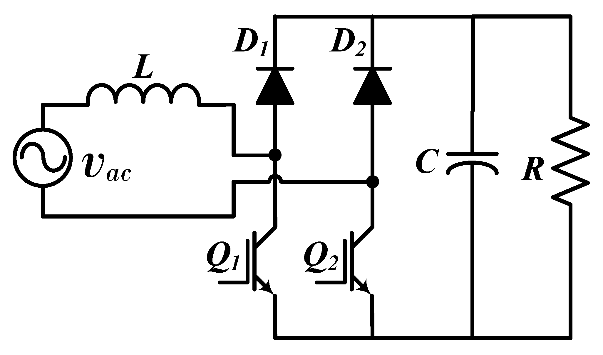
SBBC topologies are also based on the BBC topology; however, they use a half bridge composed of Q 1 and Q 2 as can be seen in Figure 1. In this topology, the inductor L is between the AC power supply and the half-bridge; basically, each switch operates independently for each semi-cycle using the same inductor for controlling the AC current.

3.1. Conventional Semi-Bridgeless Boost Converter Topology

Conventional or symmetrical SBBC topology is depicted in Figure 7 [39,40]. SBBC conventional topology can reduce conduction power losses since less semiconductors are required in the current path (current through of two semiconductors per cycle) if compared with BBC topologies [72,89].
The conventional SBBC topology has low Common-Mode (CM) and Differential-Mode (DM) noises in comparison with the conventional PFC BBC topology [34]. The DM noise and thermal stress in L can be reduced when it is added an inductor in the path of the neutral conductor [4,38]. The inductors work in series in each semicycle; in this case, the CM noise can also be reduced if both inductors are coupled [90,91].

3.2. Conventional Semi-Bridgeless Boost Converter with Soft Switching

Soft switching is performed by adding a snubber circuit composed of a switch Q 3 , an inductor L 3 , and a capacitor C 1 as shown in Figure 8. Basically, the snubber circuit allows for reducing switching losses from SBBC [92]. In addition, resonant circuits can be coupled for SBBC topologies as suggested in [93,94].

3.3. Semi-Bridgeless Boost Converter with Isolation

Figure 9 shows a modification of the SBBC conventional topology [95]. Such modification consists of adding a switch ( Q 3 ) between the half bridge and the capacitor to isolate the AC power supply and DC link bus. This topology presents a reduction of leakage current to the ground line from the grid. However, power losses can increase due to the addition of Q 3 that operates when the converter is discharging; in addition, this converter has a disadvantage that requires an additional control action for Q 3 and a greater filter in comparison with the SBBC conventional topology.

3.4. Semi-Bridgeless Boost Converter with Clamped Diodes

The topology of SBBC with clamped diodes or pseudo totem-pole SBBC topology is depicted in Figure 10. This configuration includes two additional diodes ( D 3 and D 4 ) to the symmetrical topology. As a result, this topology is built by two boost converters, each one operating in each semi-cycle of the AC sinusoidal wave [13,38,72,89,96,97,98,99,100]. For this reason, this topology is also known as dual boost PFC rectifier.
An advantage of this converter is that switches Q 1 and Q 2 can be driven with the same control signal. This topology reduces CM noise since D 3 and D 4 avoid the coupling between ground and the power supply. However, DM noise and current ripple can increase since only one inductor operates in each semi-cycle. In comparison with conventional topology with a rectifier bridge, this converter has less current ripple and also produces less DM and CM noises; consequently, a smaller filter could be used for this topology which makes it less expensive [32]. The authors in [89] designed a cascade PI controller, and they obtained a PF of 0.99 and a T H D i around 3.9%. This implies a significant energy quality improvement if the SBBC control system is also designed for harmonic mitigation. Additionally, the CM noise can also be reduced if coupling inductors are used [101] while switching losses can be reduced if a snubber circuit is implemented [63,102,103,104]. In addition, T H D i can be improved if any nonlinear control technique is implemented [11]; the authors in [11] developed a sliding mode control together with PI and an adaptive hysteresis band were proposed to reduce T H D i and, at the same time, to improve the dynamic converter response.
A modification of this topology is presented in [12]. The authors replace Q 2 by two diodes making a hybrid converter between conventional BBC and SBBC with clamped diodes. This converter can operate in low voltage and power with a classical cascade PI control.

3.5. Semi-Bridgeless Boost Converter with Clamped Switches

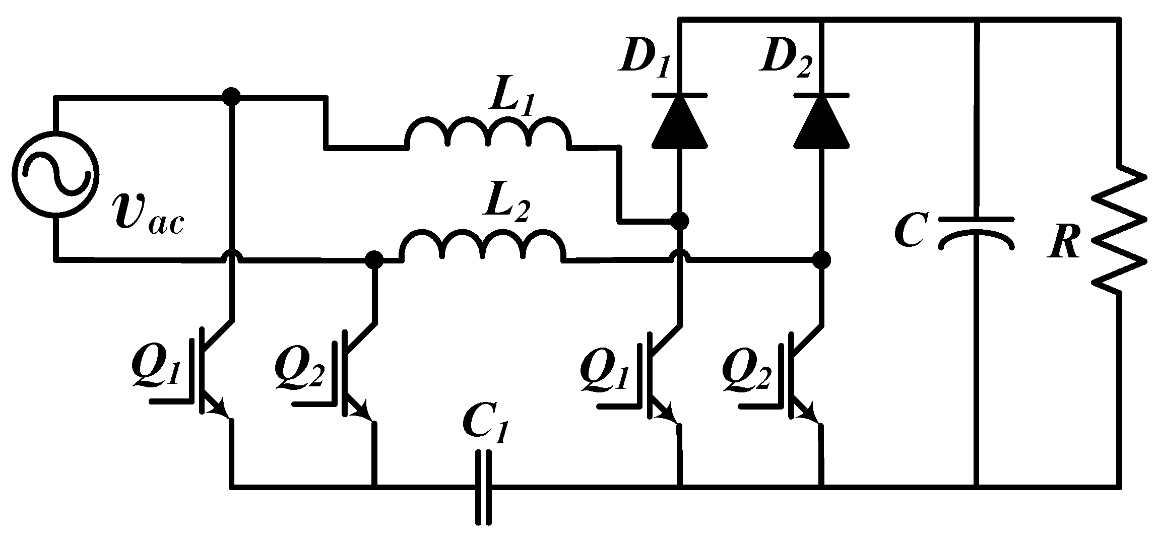
SBBC hybrid clamped topology or SBBC with active virtual ground is depicted in Figure 11 [105]. The capacitor C 1 and two clamped switches ( Q 3 and Q 4 ) are added while diodes are removed. As an advantage, it is possible to implement an LCL filter (with L 1 , L 2 and C 1 ) between the SBBC and the AC power supply; then, this filter can reduce the DM noise. In addition, this topology requires less robust EMI filters compared to the SBBC with clamp diodes’ topology. CM noise can be reduced using C 1 ; however, the conduction losses are increased. In [106], this converter is controlled by cascade PI control for Q 1 and Q 2 , operating as conventional SBBC while switches Q 3 and Q 4 have an independent control. This paper presents an application in low voltage and power with T H D i into a normative range for powers greater than 200 W. The active filter allows for reducing or eliminating (depending on the application) the passive EMI filter between the grid and converter; additionally, the switches increase conduction losses, control requirements, and implementation cost. In contrast, the SBBC topology with clamped diodes and passive EMI filter presents a similar behavior with lower design and implementation requirements.

3.6. Semi-Bridgeless Boost Converter with Clamped Diodes and Switches

SBBC based on a clamped topology with diodes and switches is depicted in Figure 12. The authors in [107] reported that this topology presents high efficiency. This topology considers two additional switches ( Q 3 and Q 4 ); consequently, each boost converter works by using two switches per semi-cycle. The main advantage corresponds to the reduction of conduction losses due to the current return path being shortened; in addition, Q 3 and Q 4 contribute to the reduction of CM noise. Please note that power losses do not increase for this topology when compared with a topology with only clamped switches; basically, clamped diodes ( D 3 and D 4 ) only operate for the pre-charge of the DC bus, being excluded from the current path in normal operation conditions or in steady state.

3.7. Semi-Bridgeless Boost Converter with Clamped Capacitors

This converter (Figure 13a) incorporates two clamped capacitors ( C 1 and C 2 ) [5]. The capacitors work as a filter with low impedance when the converter needs to operate in high frequency, which is used for CM noise mitigation. The current ripple may increase up to two times in comparison with a converter with clamped diodes; in addition, this converter presents a lower efficiency than the SBBC with clamped diodes and switches in similar applications. In this topology, the clamped capacitors must have the same values; otherwise, the converter has imbalances, increasing CM noise. In this case, the converter could need a different controller for each switch. Figure 13b presents a modification for this converter [6]; the modification includes two coupled inductors ( L 3 ) in series with l 1 and L 2 for mitigating CM noise. In this case, the capacitors are also used to reduce the magnetization current from L 3 (they present low impedance); additionally, the choke inductors present high impedance in their terminals. Then, this topology has a wide frequency range for CM noise mitigation.

3.8. Semi-Bridgeless Topology with Internal Snubber Circuit

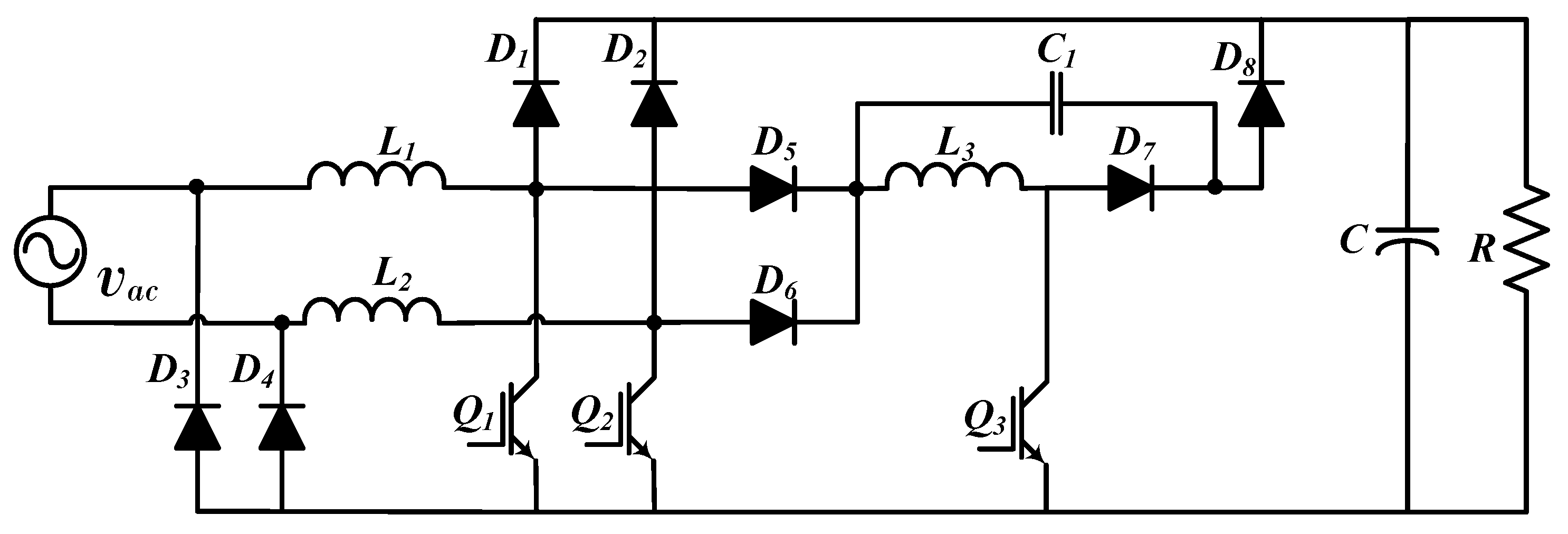
Figure 14 depicts the SBBC with an internal snubber circuit [108]. This converter has an additional switch ( Q 3 ) in comparison with the topology with clamped diodes in order to switch the converter with zero voltage transition. The main function of Q 3 is to control the snubber circuit made of diodes D 5 , D 6 , D 7 , D 8 , inductor L 3 , and capacitor C 1 . The snubber circuit provides a soft switching for Q 1 , Q 2 , and Q 3 in order to reduce switching losses and reverse recovery losses from D 1 and D 2 . Other topologies with a snubber circuit for SBBC soft switching can be consulted in [109,110,111].
In conclusion, SBBC topologies present better behavior than BBC topologies in terms of efficiency, T H D i , and losses. Therefore, SBBC topologies are suggested in applications of low voltage and medium power instead of BBC topologies [32,36,37,112].

4. Categorization of Bridgeless Boost Converters

This section categorizes the BLBC based on boost topology that basically replaces the rectifier bridge by switches or asymmetrically situating not only the switches but also the diodes of the converter branches.

4.1. Totem Pole Topology

Figure 15 depicts the conventional or asymmetrical topology based on boost converter [33,41,42,43,113,114]. Figure 15a illustrates the conventional BBC totem-pole with line rectification done by diodes; this topology has switches ( Q 1 and Q 2 ) in the first branch of the converter and diodes ( D 1 and D 2 ) in the second branch. This converter can operate in the limit of CCM and DCM, including techniques for sampling (as explained in [115]). This allows for reducing reverse-recovery of diodes and T H D i . Nonetheless, this operation mode produces a random ripple to consider in control designing. In addition, power losses can be mitigated with snubber circuits [92,116,117,118,119,120,121,122]. This topology has commonly been used in low voltage and power applications; nevertheless, in medium power applications, it is suggested to build the converter with switches ( Q 1 and Q 2 ) using GaN technology [123]. GaN switches allow for converter operation using higher switching frequencies (greater than 100KH z) with low power losses in comparison with IGBT power switches. It should be noted that the maximum switching frequency of power switches is a function of multiple factors such as structure dimensions, duty cycle, control, technology, etc. In this way, an IGBT switch can also operate at frequencies up to 100 KHz [124]; nevertheless, IGBTs are limited by their constructive features and working at high frequencies reduces their efficiency and operating current.
A modification to the totem-pole topology is shown in Figure 15b where diodes are removed and the line rectification is carried out by means of switches ( Q 3 and Q 4 ) ; additionally, it is suggested that Q 1 and Q 2 be GaN, so that it is possible to reach high power factor and efficiency with PI control outside the design operation point [125]. In [126], a BBC with GaN switches was implemented for low voltage and medium power applications. The experimental results show efficiency of 99% considering copper losses from the converter inductor and EMI filter. In the same way, in [127], a BBC totem-pole with GaN switching was implemented for low voltage and medium power applications. The authors showed that T H D i complies with the normative range with classical cascade PI control, improving the PWM modulation technique. This topology can reach a great reduction of switching power losses when used with a resonant circuit [76,128,129,130,131,132].

4.2. Bridgeless Boost Converter, Interleaved Totem-Pole

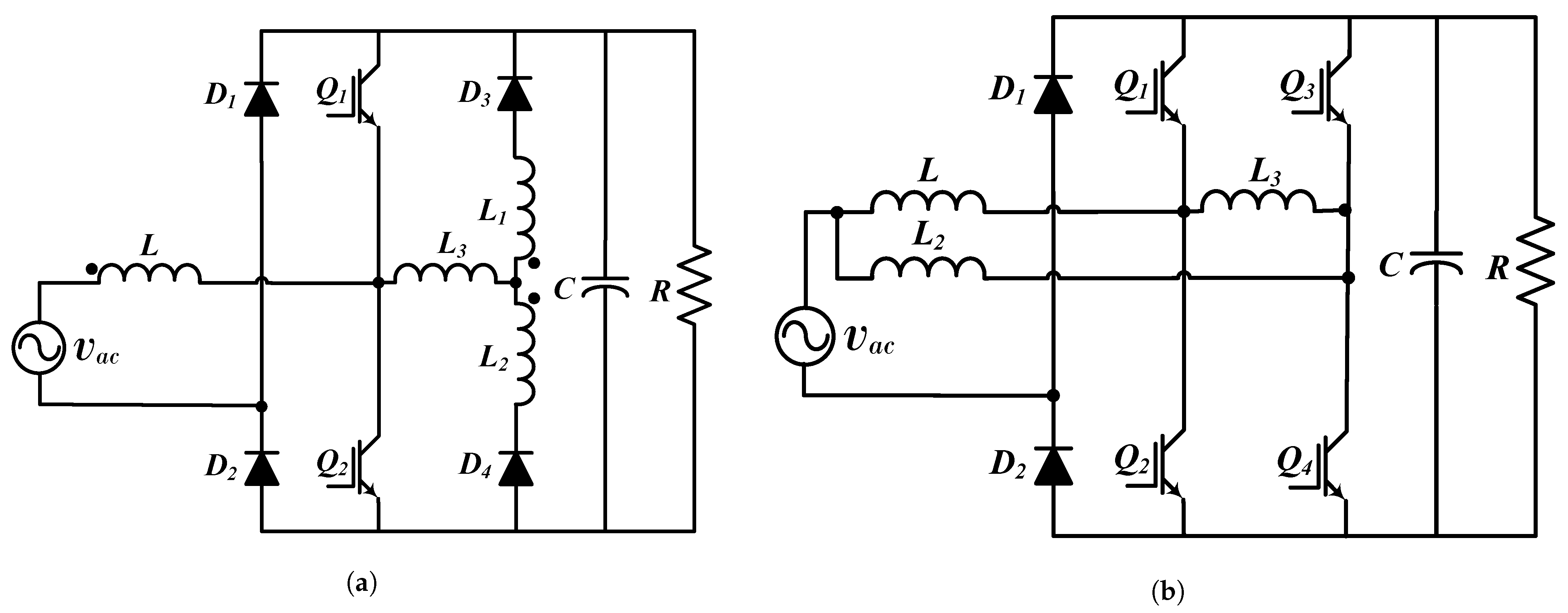
Totem-pole and GaN totem-pole topologies can be improved according to Figure 16. Figure 16a presents a BBC totem-pole with additional diodes ( D 3 and D 4 ) and inductors ( L 1 , L 2 and L 3 ) [133]. In this case, L, L 1 , and L 2 are coupling inductors and their function consists of reducing reverse recovery currents from diodes D 1 and D 2 . Diodes D 3 and D 4 contribute to ZCS of Q 1 and Q 2 . This converter is used in low voltage and power applications, and its efficiency is lower than the one of the totem-pole and GaN totem-pole (between 94% and 97%) topologies due to the additional components in the converter. In the same way, the GaN totem-pole can be modified by adding diodes D 1 and D 2 and inductors L 2 and L 3 according to Figure 16b [8,23,134]. Diodes and inductors comply with the same function as the converter in Figure 16a (reducing reverse recovery issues and contribute with ZCS); additionally, efficiency is also reduced requiring a robust control strategy and filtering to comply with T H D i limits given by the normative.

4.3. Pseudo Totem-Pole

Figure 17 depicts the pseudo totem-pole converter. This converter has two AC/DC boost rectifiers (one for each grid semi-cycle) [9,135,136]. In the positive semi-cycle, the first boost converter (formed by L 1 , Q 1 , and D 1 ) operates due to the polarization of D 4 . In the negative semi-cycle, the second boost converter (formed by L 2 , Q 2 , and D 2 ) operates due to the polarization of D 3 . This topology needs independent signals for controlling both switches [36]. Additionally, it also requires coupling inductors for EMI mitigation and snubber circuits for switching losses’ reduction [137,138]; therefore, this topology is not commonly used since a similar performance can be obtained with other BLBC topologies (with less number of components or control complexity).

5. Summary of PFC Single-Phase AC-DC Based on Topologies of a Boost Converter

This section summarizes the BBC, SBBC, and BLBC converters categorized in this paper. It was found that most of the PFC Single-Phase AC-DC Boost converter topologies are used for applications in low (L) and medium (M) voltage and power; a classification concerning these aspects is included in this section. This section also includes recommendations to help designers and developers in the process of topology selection according to their specific requirements. Table 1 includes the summary in terms of control, voltage level, power level, number of semiconductors (SM), and number of inductors and capacitors (IC) that compose each topology.
Concerning control techniques, it was found that most topologies can reach a high power factor when a linear control technique is used; however, high values of T H D i and efficiency are difficult to obtain. Basically, to reach high standards of power quality, a robust EMI filter is required, which increases the cost. It was also found that, when nonlinear control techniques are implemented, all topologies present low T H D i (lower than 6%), high power factor (greater than 0.99) and high efficiency (greater than 97%). Then, it is concluded that, by using nonlinear control techniques, it is possible to obtain a high standard of power quality and at the same time reduce the cost of the converter; however, the implementation of a nonlinear control represents a greater effort in the development stage.
BBC topologies with bidirectional switch are not recommended due to the fact that these topologies increase the number of switches; consequently, the converter cost is higher and the control technique is more difficult to develop. Moreover, a better performance in terms of dynamic response can be obtained by means of other BBC or SBBC topologies. SBBC with zero voltage transition is not recommended due to its large number of components, which make it expensive; BLBC pseudo totem-pole is not recommended since similar dynamic performance can be obtained with the conventional totem-pole topology.
The topologies presented in this paper require an input filtering process; however, SBBC converters need a less robust filter than BBC or BLBC under the same operative conditions, due to the reduction of CM noise obtained by their symmetry in construction. It was also found that a better efficiency can be obtained by using several current paths by means interleaved circuits, and reducing losses by means of snubber or resonant circuits. BLBC topologies (not symmetrical) need a conditioning circuit for isolation of control signals.

6. Conclusions

In this paper, a review and categorization regarding BBC, SBBC and BLBC topologies for PFC based on boost converter was presented; the basic operation, advantages, and disadvantages of these topologies were analyzed, including criteria for categorization which allows for unifying the technical language that is used in these types of devices. All consulted topologies need an input EMI filter and may reach high power factor (complying with IEEE Std. 519 and IEC/EN 61000-3-2) when PID controls are used; however, to reach high standards of power quality, the use of nonlinear control techniques is recommended. Basically, challenges are focused on improving energy quality concerning electromagnetic compatibility. An adequate PI tuning that includes any optimization technique can reduce the filter size; nevertheless, it could present a slow response in the face of disturbances or load changes in comparison with nonlinear control techniques. In general terms, nonlinear control can significantly reduce the filter size improving the converter behavior.
BBC is widely used in low voltage applications due to its simplicity (low components and control requirements). Nevertheless, in medium voltage and power, a robust EMI filter is required, increasing power losses, implementation cost, and control requirements. BBC topologies based on bidirectional switches are not recommended due to the fact that other topologies can carry out the same function with better electromagnetic compatibility performance and less demanding requirements not only in control but also in implementation. In conclusion, BBC topologies present an appropriate dynamic performance for low voltage and power applications. As regards medium voltage applications, the use of interleaved BBC is recommended; nevertheless, it must be considered that its rectifier bridge may produce higher EMI.
In general, topologies based on the symmetric distribution of components (SBBC) have better behavior than other topologies (BBC and BLBC) regarding efficiency and EMI when similar control strategies are implemented. In some topologies (as the clamped one), the same control signal can be used to operate all converter switches. SBBC topologies are symmetric with respect to the ground and several paths for current circulation. This reduces thermal stress in their components such as inductors and power switches. In addition, SBBC topologies can easily comply with IEEE Std. 519 and IEC/EN 61000-3-2 when PID controls are implemented while using less robust filters than BBC topologies. For these reasons, SBBC topologies are recommended for low voltage and medium power applications.

Author Contributions

Conceptualization, J.R.O.-C., G.E.M.-R., N.M.-G. and S.D.S.-Z.; Funding acquisition, N.M.-G. and J.M.L.-L.; Investigation, J.R.O.-C., G.E.M.-R. and N.M.-G.; Project administration, N.M.-G. and J.M.L.-L.; Resources, J.R.O.-C., G.E.M.-R., N.M.-G. and J.M.L.-L.; Supervision, N.M.-G. and J.M.L.-L.; Writing—original draft, J.R.O.-C. and G.E.M.-R.; Writing—review and editing, N.M.-G., J.M.L.-L. and S.D.S.-Z. All authors have read and agreed to the published version of the manuscript.

Funding

This research was funded by the Colombia Scientific Program within the framework of the so-called Ecosistema Científico (Contract No. FP44842- 218-2018).

Institutional Review Board Statement

Not applicable.

Informed Consent Statement

Not applicable.

Data Availability Statement

Not applicable.

Acknowledgments

The authors thank Corporacion Universitaria Minuto de Dios—UNIMINUTO for the support received in this research. The authors also acknowledge the support of the Colombia Scientific Program within the framework of the call Ecosistema Científico (Contract No. FP44842-218-2018).

Conflicts of Interest

The authors declare no conflict of interest.

References

  1. Ortatepe, Z.; Karaarslan, A. DSP-based comparison of PFC control techniques applied on bridgeless converter. IET Power Electron. 2020, 13, 317–323. [Google Scholar] [CrossRef]
  2. Qiao, C.; Smedley, K.M. A topology survey of single-stage power factor corrector with a boost type input-current-shaper. IEEE Trans. Power Electron. 2001, 16, 360–368. [Google Scholar] [CrossRef]
  3. Kim, J.; Choi, H.; Won, C. New Modulated Carrier Controlled PFC Boost Converter. IEEE Trans. Power Electron. 2018, 33, 4772–4782. [Google Scholar] [CrossRef]
  4. Jaiswal, D.; Singh, K.P.; Tiwari, A.N. Analysis of Bridgeless PFC Boost Converter. Int. J. Eng. Res. Technol. (IJERT) 2012, 1, 1–6. [Google Scholar]
  5. Soldano, M.; Lu, B. EMI Noise Reduction Circuit and Method for Bridgeless PFC Circuit. U.S. Patent US7215560B2, 8 May 2007. [Google Scholar]
  6. Wildash, K.D. Bridgeless Boost PFC Circuits and Systems with Reduced Common Mode EMI. U.S. Patent US8289737B2, 16 October 2012. [Google Scholar]
  7. Lin, X.; Wang, F.; Iu, H.H.C. A New Bridgeless High Step-up Voltage Gain PFC Converter with Reduced Conduction Losses and Low Voltage Stress. Energies 2018, 11, 2640. [Google Scholar] [CrossRef] [Green Version]
  8. Park, M.; Baek, J.; Jeong, Y.; Moon, G. An Interleaved Totem-Pole Bridgeless Boost PFC Converter with Soft-Switching Capability Adopting Phase-Shifting Control. IEEE Trans. Power Electron. 2019, 34, 10610–10618. [Google Scholar] [CrossRef]
  9. Mohanraj, K.; Danya Bersis, C.; Dash, S.S. Comparison and Simulation of Various PFC Boost Converters. In Power Electronics and Renewable Energy Systems; Lecture Notes in Electrical Engineering; Kamalakannan, C., Suresh, L.P., Dash, S.S., Panigrahi, B.K., Eds.; Springer: New Delhi, India, 2015; pp. 1445–1452. [Google Scholar] [CrossRef]
  10. Lee, J.; Chae, H. 6.6-kW Onboard Charger Design Using DCM PFC Converter With Harmonic Modulation Technique and Two-Stage DC/DC Converter. IEEE Trans. Ind. Electron. 2014, 61, 1243–1252. [Google Scholar] [CrossRef]
  11. Mejía-Ruiz, G.E.; Muñoz-Galeano, N.; Ortiz-Castrillón, J.R. Banda de Histéresis Adaptativa para un Convertidor AC-DC Elevador sin Puente, con Correccion del Factor de Potencia y Control por Modos Deslizantes. Inf. Tecnológica 2019, 30, 283–292. [Google Scholar] [CrossRef] [Green Version]
  12. Cho, Y. A Low Cost Single-Switch Bridgeless Boost PFC Converter. Int. J. Power Electron. Drive Syst. (IJPEDS) 2014, 4, 256–264. [Google Scholar] [CrossRef]
  13. Rajappan, S.C.; John, N. An efficient bridgeless power factor correction boost converter. In Proceedings of the 2013 7th International Conference on Intelligent Systems and Control (ISCO), Coimbatore, India, 4–5 January 2013; pp. 55–59. [Google Scholar] [CrossRef]
  14. Ochoa, L.F.; Dent, C.J.; Harrison, G.P. Distribution Network Capacity Assessment: Variable DG and Active Networks. IEEE Trans. Power Syst. 2010, 25, 87–95. [Google Scholar] [CrossRef] [Green Version]
  15. Chen, X.; Dall’Anese, E.; Zhao, C.; Li, N. Aggregate Power Flexibility in Unbalanced Distribution Systems. IEEE Trans. Smart Grid 2020, 11, 258–269. [Google Scholar] [CrossRef]
  16. Jovanovic, M.M.; Jang, Y. State-of-the-art, single-phase, active power-factor-correction techniques for high-power applications—An overview. IEEE Trans. Ind. Electron. 2005, 52, 701–708. [Google Scholar] [CrossRef]
  17. Chen, Z.; Davari, P.; Wang, H. Single-Phase Bridgeless PFC Topology Derivation and Performance Benchmarking. IEEE Trans. Power Electron. 2020, 35, 9238–9250. [Google Scholar] [CrossRef]
  18. Singh, B.; Singh, B.N.; Chandra, A.; Al-Haddad, K.; Pandey, A.; Kothari, D.P. A review of single-phase improved power quality AC-DC converters. IEEE Trans. Ind. Electron. 2003, 50, 962–981. [Google Scholar] [CrossRef] [Green Version]
  19. Huang, Q.; Huang, A.Q. Review of GaN totem-pole bridgeless PFC. CPSS Trans. Power Electron. Appl. 2017, 2, 187–196. [Google Scholar] [CrossRef]
  20. Kushwaha, R.; Singh, B. Interleaved Landsman Converter Fed EV Battery Charger With Power Factor Correction. IEEE Trans. Ind. Appl. 2020, 56, 4179–4192. [Google Scholar] [CrossRef]
  21. Truntič, M.; Konjedic, T.; Milanovič, M.; Šlibar, P.; Rodič, M. Control of integrated single-phase PFC charger for EVs. IET Power Electron. 2018, 11, 1804–1812. [Google Scholar] [CrossRef]
  22. Lu, W.; Han, J.; Li, S.; Iu, H.H. Mitigating Line Frequency Instability of Boost PFC Converter Under Proportional Outer-Voltage Loop with Additional Third Current-Harmonic Feedforward Compensation. IEEE Trans. Circuits Syst. I Regul. Pap. 2019, 66, 4528–4541. [Google Scholar] [CrossRef]
  23. Su, B.; Lu, Z. An Interleaved Totem-Pole Boost Bridgeless Rectifier with Reduced Reverse-Recovery Problems for Power Factor Correction. IEEE Trans. Power Electron. 2010, 25, 1406–1415. [Google Scholar] [CrossRef]
  24. Han, J.; Baek, J.; Jeong, Y.; Yeon, C.; Moon, G. A simple THD improving method for CCM boost PFC converter under mixed conduction mode operation. In Proceedings of the 2017 IEEE 3rd International Future Energy Electronics Conference and ECCE Asia (IFEEC 2017—ECCE Asia), Kaohsiung, Taiwan, 27 July 2017; pp. 466–470. [Google Scholar] [CrossRef]
  25. IEEE. Recommended Practice and Requirements for Harmonic Control in Electric Power Systems; IEEE Std 519-2014 (Revision of IEEE Std 519-1992); IEEE: New York, NY, USA, 11 June 2014; pp. 1–29. [Google Scholar] [CrossRef]
  26. Zhu, H.; Liu, D.; Zhang, X.; Qu, F. Reliability of Boost PFC Converters with Improved EMI Filters. Electronics 2018, 7, 413. [Google Scholar] [CrossRef] [Green Version]
  27. Nair, H.S.; Lakshminarasamma, N. Challenges in achieving high performance in boost PFC converter. In Proceedings of the 2017 IEEE International Conference on Signal Processing, Informatics, Communication and Energy Systems (SPICES), Kollam, India, 2 November 2017; pp. 1–6. [Google Scholar] [CrossRef]
  28. Xu, H.; Chen, D.; Xue, F.; Li, X. Optimal Design Method of Interleaved Boost PFC for Improving Efficiency from Switching Frequency, Boost Inductor, and Output Voltage. IEEE Trans. Power Electron. 2019, 34, 6088–6107. [Google Scholar] [CrossRef]
  29. Krishna, S.A.; Abraham, L. Boost converter based power factor correction for single phase rectifier using fuzzy logic control. In Proceedings of the 2014 First International Conference on Computational Systems and Communications (ICCSC), Trivandrum, India, 17–18 December 2014; pp. 122–126. [Google Scholar] [CrossRef]
  30. Sreevidya, E.V.; Jegathesan, V. A modified control approach for power factor correction in AC/DC boost converter. In Proceedings of the 2015 International Conference on Innovations in Information, Embedded and Communication Systems (ICIIECS), Coimbatore, India, 19–20 March 2015; pp. 1–6. [Google Scholar] [CrossRef]
  31. Hu, J.; Xiao, W.; Zhang, B.; Qiu, D.; Ho, C.N.M. A Single Phase Hybrid Interleaved Parallel Boost PFC Converter. In Proceedings of the 2018 IEEE Energy Conversion Congress and Exposition (ECCE), Portland, OR, USA, 23–27 September 2018; pp. 2855–2859. [Google Scholar] [CrossRef]
  32. Ancuti, M.; Svoboda, M.; Musuroi, S.; Hedes, A.; Olarescu, N. Boost PFC converter versus bridgeless boost PFC converter EMI analysis. In Proceedings of the 2014 International Conference on Applied and Theoretical Electricity (ICATE), Craiova, Romania, 23–25 October 2014; pp. 1–6. [Google Scholar] [CrossRef]
  33. Ma, H.; Lai, J.; Zheng, C.; Sun, P. A High-Efficiency Quasi-Single-Stage Bridgeless Electrolytic Capacitor-Free High-Power AC–DC Driver for Supplying Multiple LED Strings in Parallel. IEEE Trans. Power Electron. 2016, 31, 5825–5836. [Google Scholar] [CrossRef]
  34. Ahamad, I.; Asim, M.; Ranjan Sarkar, P.; Khan, F. Comparison of Conventional PFC Boost Converter and Bridgeless PFC Boost Converter. Int. J. Innov. Res. Electr. Electron. Instrum. Control Eng. 2016, 4, 210–212. [Google Scholar] [CrossRef]
  35. Lin, W.; Chen, H.; Fang, Y. A Single-stage PFC by Integrating quasi-Bridgeless Boost and LLC Converter. In Proceedings of the 2018 IEEE International Telecommunications Energy Conference (INTELEC), Turino, Italy, 7–11 October 2018; pp. 1–5. [Google Scholar] [CrossRef]
  36. Huber, L.; Jang, Y.; Jovanovic, M.M. Performance Evaluation of Bridgeless PFC Boost Rectifiers. IEEE Trans. Power Electron. 2008, 23, 1381–1390. [Google Scholar] [CrossRef]
  37. Chellappan, S. A comparative analysis of topologies for a bridgeless-boost PFC circuit. Analog. Des. J. 2018, 3, 1–3. [Google Scholar]
  38. Musavi, F.; Eberle, W.; Dunford, W.G. A Phase-Shifted Gating Technique with Simplified Current Sensing for the Semi-Bridgeless AC–DC Converter. IEEE Trans. Veh. Technol. 2013, 62, 1568–1576. [Google Scholar] [CrossRef]
  39. Jacoboski, M.J.; de Bastiani Lange, A.; Heldwein, M.L. Closed-Form Solution for Core Loss Calculation in Single-Phase Bridgeless PFC Rectifiers Based on the iGSE Method. IEEE Trans. Power Electron. 2018, 33, 4599–4604. [Google Scholar] [CrossRef]
  40. Nguyen, H.V.; Lee, D. Reducing the dc-Link Capacitance: A Bridgeless PFC Boost Rectifier That Reduces the Second-Order Power Ripple at the dc Output. IEEE Ind. Appl. Mag. 2018, 24, 23–34. [Google Scholar] [CrossRef]
  41. Salmon, J.C. Circuit topologies for PWM boost rectifiers operated from 1-phase and 3-phase AC supplies and using either single or split DC rail voltage outputs. In Proceedings of the 1995 IEEE Applied Power Electronics Conference and Exposition—APEC’95, Dallas, TX, USA, 5–9 March 1995; Volume 1, pp. 473–479. [Google Scholar] [CrossRef]
  42. Alam, M.; Eberle, W.; Gautam, D.S.; Botting, C.; Dohmeier, N.; Musavi, F. A Hybrid Resonant Pulse-Width Modulation Bridgeless AC–DC Power Factor Correction Converter. IEEE Trans. Ind. Appl. 2017, 53, 1406–1415. [Google Scholar] [CrossRef]
  43. Lamo, P.; López, F.; Pigazo, A.; Azcondo, F.J. Stability and Performance Assessment of Single-Phase T/4 PLLs With Secondary Control Path in Current Sensorless Bridgeless PFCs. IEEE J. Emerg. Sel. Top. Power Electron. 2018, 6, 674–685. [Google Scholar] [CrossRef]
  44. Figueiredo, J.P.M.; Tofoli, F.L.; Silva, B.L.A. A review of single-phase PFC topologies based on the boost converter. In Proceedings of the 2010 9th IEEE/IAS International Conference on Industry Applications—INDUSCON 2010, Sao Paulo, Brazil, 8–10 November 2010; pp. 1–6. [Google Scholar] [CrossRef]
  45. Mahmud, K.; Tao, L. Power factor correction by PFC boost topology using average current control method. In Proceedings of the 2013 IEEE Global High Tech Congress on Electronics, Shenzhen, China, 17–19 November 2013; pp. 16–20. [Google Scholar] [CrossRef]
  46. Urrea-Quintero, J.H.; Muñoz-Galeano, N.; Gómez-Echavarría, L.M. Analysis and Control of Power Electronic Converters Based on a System Zero Locations Approach. Appl. Mod. Control. 2018. [Google Scholar] [CrossRef] [Green Version]
  47. Park, S.; Choi, S. Soft-Switched CCM Boost Converters With High Voltage Gain for High-Power Applications. IEEE Trans. Power Electron. 2010, 25, 1211–1217. [Google Scholar] [CrossRef]
  48. Gurpinar, E.; Castellazzi, A. Single-Phase T-Type Inverter Performance Benchmark Using Si IGBTs, SiC MOSFETs, and GaN HEMTs. IEEE Trans. Power Electron. 2016, 31, 7148–7160. [Google Scholar] [CrossRef]
  49. Scognamillo, C.; Catalano, A.P.; Riccio, M.; d’Alessandro, V.; Codecasa, L.; Borghese, A.; Tripathi, R.N.; Castellazzi, A.; Breglio, G.; Irace, A. Compact Modeling of a 3.3 kV SiC MOSFET Power Module for Detailed Circuit-Level Electrothermal Simulations Including Parasitics. Energies 2021, 14, 4683. [Google Scholar] [CrossRef]
  50. Ren, X.; Wu, Y.; Guo, Z.; Zhang, Z.; Chen, Q. An Online Monitoring Method of Circuit Parameters for Variable On-Time Control in CRM Boost PFC Converters. IEEE Trans. Power Electron. 2019, 34, 1786–1797. [Google Scholar] [CrossRef]
  51. Vinay, B.K.; Sindhu, B.M. Resonant Circuit with Soft-Switching Performance of a Boost Converter for PFC with ZVS and/or ZCS. Int. J. Sci. Technol. Eng. 2016, 2, 113–118. [Google Scholar]
  52. Ren, X.; Zhou, Y.; Guo, Z.; Wu, Y.; Zhang, Z.; Chen, Q. Analysis and Improvement of Capacitance Effects in 360–800 Hz Variable On-Time Controlled CRM Boost PFC Converters. IEEE Trans. Power Electron. 2020, 35, 7480–7491. [Google Scholar] [CrossRef]
  53. Wang, J.; Eto, H.; Kurokawa, F. Optimal Zero-Voltage-Switching Method and Variable ON-Time Control for Predictive Boundary Conduction Mode Boost PFC Converter. IEEE Trans. Ind. Appl. 2020, 56, 527–540. [Google Scholar] [CrossRef]
  54. Denisov, Y.O.; Stepenko, S.A.; Gorodny, A.N.; Kravchenko, A.O. Input current parameters analysis for PFC based on quasi-resonant and conventional boost converters. In Proceedings of the 2014 IEEE 34th International Scientific Conference on Electronics and Nanotechnology (ELNANO), Kyiv, Ukraine, 15–18 April 2014; pp. 393–397. [Google Scholar] [CrossRef]
  55. Kim, Y.W.; Kim, J.H.; Choi, K.Y.; Suh, B.S.; Kim, R.Y. A Novel Soft-Switched Auxiliary Resonant Circuit of a PFC ZVT-PWM Boost Converter for an Integrated Multichip Power Module Fabrication. IEEE Trans. Ind. Appl. 2013, 49, 2802–2809. [Google Scholar] [CrossRef]
  56. Huber, L.; Irving, B.T.; Jovanovic, M.M. Effect of Valley Switching and Switching-Frequency Limitation on Line-Current Distortions of DCM/CCM Boundary Boost PFC Converters. IEEE Trans. Power Electron. 2009, 24, 339–347. [Google Scholar] [CrossRef]
  57. Guo, Z.; Ren, X.; Gui, H.; Wu, Y.; Zhang, Z.; Chen, Q. A universal variable on-time compensation to improve THD of high-frequency CRM boost PFC converter. In Proceedings of the 2016 IEEE Energy Conversion Congress and Exposition (ECCE), Milwaukee, WI, USA, 18–22 September 2016; pp. 1–6. [Google Scholar] [CrossRef]
  58. Li, R.T.H.; Chung, H.S.H.; Sung, A.K.T. Passive Lossless Snubber for Boost PFC With Minimum Voltage and Current Stress. IEEE Trans. Power Electron. 2010, 25, 602–613. [Google Scholar] [CrossRef]
  59. Chen, Y.L.; Chen, Y.M. Line Current Distortion Compensation for DCM/CRM Boost PFC Converters. IEEE Trans. Power Electron. 2016, 31, 2026–2038. [Google Scholar] [CrossRef]
  60. Lee, S.W.; Do, H.L. Soft-Switching Two-Switch Resonant AC–DC Converter With High Power Factor. IEEE Trans. Ind. Electron. 2016, 63, 2083–2091. [Google Scholar] [CrossRef]
  61. Liu, X.; Liu, W.; He, M.; Wang, W.; Zhou, Q.; Xu, J. Boost-Type Single-Stage Step-Down Resonant Power Factor Correction Converter. IEEE Trans. Ind. Electron. 2020. [Google Scholar] [CrossRef]
  62. Das, P.; Pahlevaninezhad, M.; Drobnik, J.; Moschopoulos, G.; Jain, P.K. A Nonlinear Controller Based on a Discrete Energy Function for an AC/DC Boost PFC Converter. IEEE Trans. Power Electron. 2013, 28, 5458–5476. [Google Scholar] [CrossRef]
  63. Zeng, J.; Zhang, G.; Yu, S.S.; Zhang, B.; Zhang, Y. LLC resonant converter topologies and industrial application—A review. Chin. J. Electr. Eng. 2020, 6, 73–84. [Google Scholar] [CrossRef]
  64. De Gusseme, K.; Van de Sype, D.M.; Van den Bossche, A.P.M.; Melkebeek, J.A. Input-Current Distortion of CCM Boost PFC Converters Operated in DCM. IEEE Trans. Ind. Electron. 2007, 54, 858–865. [Google Scholar] [CrossRef]
  65. Kadyan, M.D.; Dabass, J. Closed Loop Controlled Bridgeless PFC Boost Converter Fed DC Drive. Int. J. Adv. Res. Eng. Technol. 2015, 3, 69–72. [Google Scholar]
  66. Zhang, W.; Feng, G.; Liu, Y.F.; Wu, B. A digital power factor correction (PFC) control strategy optimized for DSP. IEEE Trans. Power Electron. 2004, 19, 1474–1485. [Google Scholar] [CrossRef]
  67. Baek, J.I.; Kim, J.K.; Lee, J.B.; Youn, H.S.; Moon, G.W. A Boost PFC Stage Utilized as Half-Bridge Converter for High-Efficiency DC–DC Stage in Power Supply Unit. IEEE Trans. Power Electron. 2017, 32, 7449–7457. [Google Scholar] [CrossRef]
  68. Wei, Y.; Luo, Q.; Wang, J.; Pengju, S. Analysis and design of the DCM operation boost PFC converter with magnetic control. IET Power Electron. 2019, 12, 3697–3706. [Google Scholar] [CrossRef]
  69. Nair, H.S.; Lakshmi Narasamma, N. An Improved Digital Algorithm for Boost PFC Converter Operating in Mixed Conduction Mode. IEEE J. Emerg. Sel. Top. Power Electron. 2020, 8, 4235–4245. [Google Scholar] [CrossRef]
  70. Zhang, F.; Xu, J. A Novel PCCM Boost PFC Converter with Fast Dynamic Response. IEEE Trans. Ind. Electron. 2011, 58, 4207–4216. [Google Scholar] [CrossRef]
  71. Akter, K.; Sarowar, G.; Faisal, F.; Oninda, M.A.M.; Hoque, M.A. Input Switched Single Phase AC-DC PFC Boost Converter for High-Performance. In Proceedings of the 2018 International Conference on Advancement in Electrical and Electronic Engineering (ICAEEE), Gazipur, Bangladesh, 22–24 November 2018; pp. 1–4. [Google Scholar] [CrossRef]
  72. Sudheer, L.; Kanimozhi, G.; Sreedevi, V.T. Integrator controlled semi-bridgelesss PFC boost converter. In Proceedings of the 2015 International Conference on Circuits, Power and Computing Technologies (ICCPCT-2015), Nagercoil, India, 19–20 March 2015; pp. 1–6. [Google Scholar] [CrossRef]
  73. Yao, K.; Chen, K.; Mao, C.; Tang, H.; Li, L.; Wu, C.; Zhang, Z.; Ma, C. Optimal Switching Frequency Variation Range Control for Critical Conduction Mode Boost Power Factor Correction Converter. IEEE Trans. Ind. Electron. 2021, 68, 1197–1209. [Google Scholar] [CrossRef]
  74. Ren, X.; Guo, Z.; Wu, Y.; Zhang, Z.; Chen, Q. Adaptive LUT-Based Variable On-Time Control for CRM Boost PFC Converters. IEEE Trans. Power Electron. 2018, 33, 8123–8136. [Google Scholar] [CrossRef]
  75. De Gusseme, K.; Ryckaert, W.R.; Van de Sype, D.M.; Ghijselen, J.A.; Melkebeek, J.A.; Vandevelde, L. A Boost PFC Converter With Programmable Harmonic Resistance. IEEE Trans. Ind. Appl. 2007, 43, 742–750. [Google Scholar] [CrossRef]
  76. Li, G.; Xia, J.; Wang, K.; Deng, Y.; He, X.; Wang, Y. A Single-Stage Interleaved Resonant Bridgeless Boost Rectifier with High-Frequency Isolation. IEEE J. Emerg. Sel. Top. Power Electron. 2020, 8, 1767–1781. [Google Scholar] [CrossRef]
  77. Rasoulinezhad, R.; Abosnina, A.A.; Khodabakhsh, J.; Moschopoulos, G. An AC-DC Interleaved ZCS-PWM Boost Converter With Reduced Auxiliary Switch RMS Current Stress. IEEE Access 2021, 9, 41320–41333. [Google Scholar] [CrossRef]
  78. Wang, H.; Dusmez, S.; Khaligh, A. Design considerations for a level-2 on-board PEV charger based on interleaved boost PFC and LLC resonant converters. In Proceedings of the 2013 IEEE Transportation Electrification Conference and Expo (ITEC), Detroit, MI, USA, 16–19 June 2013; pp. 1–8. [Google Scholar] [CrossRef]
  79. Ancuti, M.; Svoboda, M.; Musuroi, S.; Hedes, A.; Olarescu, N.; Wienmann, M. Boost interleaved PFC versus bridgeless boost interleaved PFC converter performance/efficiency analysis. In Proceedings of the 2014 International Conference on Applied and Theoretical Electricity (ICATE), Craiova, Romania, 23–25 October 2014; pp. 1–6. [Google Scholar] [CrossRef]
  80. Nussbaumer, T.; Raggl, K.; Kolar, J.W. Design Guidelines for Interleaved Single-Phase Boost PFC Circuits. IEEE Trans. Ind. Electron. 2009, 56, 2559–2573. [Google Scholar] [CrossRef]
  81. Raggl, K.; Nussbaumer, T.; Doerig, G.; Biela, J.; Kolar, J.W. Comprehensive Design and Optimization of a High-Power-Density Single-Phase Boost PFC. IEEE Trans. Ind. Electron. 2009, 56, 2574–2587. [Google Scholar] [CrossRef]
  82. Pahlevani, M.; Pan, S.; Eren, S.; Bakhshai, A.; Jain, P. An Adaptive Nonlinear Current Observer for Boost PFC AC/DC Converters. IEEE Trans. Ind. Electron. 2014, 61, 6720–6729. [Google Scholar] [CrossRef]
  83. Venkatesh, S.; Sarveswararao, D.; Nikhitha, G.; Mehanaz, S. Bridgeless Boost PFC Rectifier with High Efficiency. Int. Res. J. Eng. Technol. (IRJET) 2019, 6, 3741–3747. [Google Scholar]
  84. Fardoun, A.A.; Ismail, E.H.; Al-Saffar, M.A.; Sabzali, A.J. A Bridgeless Resonant Pseudoboost PFC Rectifier. IEEE Trans. Power Electron. 2014, 29, 5949–5960. [Google Scholar] [CrossRef]
  85. Aswathy, J.S.; Mala, K. Implementation of bridgeless resonant pseudo boost PFC rectifier with enabling window control. In Proceedings of the 2015 International Conference on Circuits, Power and Computing Technologies (ICCPCT-2015), Nagercoil, India, 19–20 March 2015; pp. 1–5. [Google Scholar] [CrossRef]
  86. Sreekala, D.K.; Krishnadas, A. A Bridgeless Resonant Pseudo Boost PFC Rectifier Based Electronic Ballast for Compact Fluorscent Lamp. Int. J. Adv. Res. Electr. Electron. Instrum. Eng. 2015, 4, 7662–7672. [Google Scholar]
  87. Liu, T.; Xin, X.; Zeng, J.; Ying, J.; Zhao, W. Bridgeless PFC Converter with Low Common-Mode Noise and High Power Density. U.S. Patent US20070279955A1, 20 October 2007. [Google Scholar]
  88. Kim, Y.; Sung, W.; Lee, B. Comparative Performance Analysis of High Density and Efficiency PFC Topologies. IEEE Trans. Power Electron. 2014, 29, 2666–2679. [Google Scholar] [CrossRef]
  89. Mejía-Ruiz, G.; Muñoz-Galeano, N.; Lopez-Lezama, J. Modeling and development of a bridgeless PFC Boost rectifier. Rev. Fac. Ing. 2017, 9–21. [Google Scholar] [CrossRef] [Green Version]
  90. Gopinath, M.; Ramareddy, S. A brief analysis on bridgeless boost PFC converter. In Proceedings of the International Conference on Sustainable Energy and Intelligent Systems (SEISCON 2011), Chennai, India, 20–22 July 2011; pp. 242–246. [Google Scholar] [CrossRef]
  91. Jang, Y.; Jovanovic, M.M. A Bridgeless PFC Boost Rectifier With Optimized Magnetic Utilization. IEEE Trans. Power Electron. 2009, 24, 85–93. [Google Scholar] [CrossRef]
  92. Muhammad, K.S.B.; Lu, D.D. ZCS Bridgeless Boost PFC Rectifier Using Only Two Active Switches. IEEE Trans. Ind. Electron. 2015, 62, 2795–2806. [Google Scholar] [CrossRef]
  93. Tahami, F.; Yazdani, F. Zero-voltage-transition with dual resonant tank for bridgeless boost PFC rectifier with low current stress. In Proceedings of the 2016 7th Power Electronics and Drive Systems Technologies Conference (PEDSTC), Tehran, Iran, 16–18 February 2016; pp. 241–247. [Google Scholar] [CrossRef]
  94. Alam, M.; Eberle, W.; Dohmeier, N. An inrush limited, surge tolerant hybrid resonant bridgeless PWM AC-DC PFC converter. In Proceedings of the 2014 IEEE Energy Conversion Congress and Exposition (ECCE), Pittsburgh, PA, USA, 14–18 September 2014; pp. 5647–5651. [Google Scholar] [CrossRef]
  95. Xu, M.; CHEN, Q.L. AC-to-DC Conversion Apparatus and Related Control Manner Thereof. U.S. Patent US8780597B2, 15 July 2014. [Google Scholar]
  96. Chen, Y.; Dai, W.; Zhou, J.; Hu, E. Study and design of a novel three-phase bridgeless boost power factor correction. IET Power Electron. 2014, 7, 2013–2021. [Google Scholar] [CrossRef]
  97. Marcos-Pastor, A.; Vidal-Idiarte, E.; Cid-Pastor, A.; Martínez-Salamero, L. Loss-Free Resistor-Based Power Factor Correction Using a Semi-Bridgeless Boost Rectifier in Sliding-Mode Control. IEEE Trans. Power Electron. 2015, 30, 5842–5853. [Google Scholar] [CrossRef] [Green Version]
  98. Aamir, M.; Mekhilef, S. An Online Transformerless Uninterruptible Power Supply (UPS) System with a Smaller Battery Bank for Low-Power Applications. IEEE Trans. Power Electron. 2017, 32, 233–247. [Google Scholar] [CrossRef]
  99. Singh, S.; Singh, B.; Bhuvaneswari, G.; Bist, V. A Power Quality Improved Bridgeless Converter-Based Computer Power Supply. IEEE Trans. Ind. Appl. 2016, 52, 4385–4394. [Google Scholar] [CrossRef]
  100. Tseng, S.Y.; Fan, J.H. Bridgeless Boost Converter with an Interleaving Manner for PFC Applications. Electronics 2021, 10, 296. [Google Scholar] [CrossRef]
  101. Yungtaek, J.; Milan, J. Power Factor Correction Rectifier Having Independent Inductive Components. U.S. Patent US 7265650 B2, 4 September 2007. [Google Scholar]
  102. Hua, C.; Fang, Y.; Huang, C. Zero-voltage-transition bridgeless power factor correction rectifier with soft-switched auxiliary circuit. IET Power Electron. 2016, 9, 546–552. [Google Scholar] [CrossRef]
  103. Jeong, Y.; Kim, J.; Moon, G. A Bridgeless Dual Boost Rectifier with Soft-Switching Capability and Minimized Additional Conduction Loss. IEEE Trans. Ind. Electron. 2018, 65, 2226–2233. [Google Scholar] [CrossRef]
  104. Kim, H.S.; Baek, J.W.; Ryu, M.H.; Kim, J.H.; Jung, J.H. The High-Efficiency Isolated AC–DC Converter Using the Three-Phase Interleaved LLC Resonant Converter Employing the Y-Connected Rectifier. IEEE Trans. Power Electron. 2014, 29, 4017–4028. [Google Scholar] [CrossRef]
  105. Ho, N.M.; Li, T.H. Bridgeless Power Factor Correction Circuit. U.S. Patent US9093917B2, 28 July 2015. [Google Scholar]
  106. Ho, C.N.M.; Li, R.T.; Siu, K.K. Active Virtual Ground—Bridgeless PFC Topology. IEEE Trans. Power Electron. 2017, 32, 6206–6218. [Google Scholar] [CrossRef]
  107. Mao, H.; Fu, D.; Cai, B. High Efficiency Bridgeless PFC Converter and Method. U.S. Patent US8385032B1, 26 February 2013. [Google Scholar]
  108. Hu, W.; Kang, Y.; Wang, X.; Zhou, X. Novel zero-voltage transition semi bridgeless boost PFC converter with soft switching auxiliary switch. In Proceedings of the 2014 IEEE Energy Conversion Congress and Exposition (ECCE), Pittsburgh, PA, USA, 14–18 September 2014; pp. 2707–2712. [Google Scholar] [CrossRef]
  109. Tsai, H.; Hsia, T.; Chen, D. A Family of Zero-Voltage-Transition Bridgeless Power-Factor-Correction Circuits with a Zero-Current-Switching Auxiliary Switch. IEEE Trans. Ind. Electron. 2011, 58, 1848–1855. [Google Scholar] [CrossRef]
  110. Ramezani, M.; Madani, S.M. New zero-voltage-switching bridgeless P, using an improved auxiliary circuit. IET Power Electron. 2011, 4, 732–741. [Google Scholar] [CrossRef]
  111. Wang, C.M. A novel ZCS-PWM power-factor preregulator with reduced conduction losses. IEEE Trans. Ind. Electron. 2005, 52, 689–700. [Google Scholar] [CrossRef]
  112. Musavi, F.; Eberle, W.; Dunford, W.G. A phase shifted semi-bridgeless boost power factor corrected converter for plug in hybrid electric vehicle battery chargers. In Proceedings of the 2011 Twenty-Sixth Annual IEEE Applied Power Electronics Conference and Exposition (APEC), Fort Worth, TX, USA, 6–11 March 2011; pp. 821–828. [Google Scholar] [CrossRef]
  113. Lee, Y.; Kim, C.; Baek, J.; Kim, D.; Moon, G. A Zero-Voltage-Switching Totem-pole Bridgeless Boost Power Factor Correction Rectifier having Minimized Conduction Losses. In Proceedings of the 2018 International Power Electronics Conference (IPEC-Niigata 2018—ECCE Asia), Niigata, Japan, 20–24 May 2018; pp. 3538–3543. [Google Scholar] [CrossRef]
  114. Zhao, C.; Wu, X. Accurate Operating Analysis of Boundary Mode Totem-Pole Boost PFC Converter Considering the Reverse Recovery of mosfet. IEEE Trans. Power Electron. 2018, 33, 10038–10043. [Google Scholar] [CrossRef]
  115. Su, B.; Zhang, J.; Lu, Z. Totem-Pole Boost Bridgeless PFC Rectifier with Simple Zero-Current Detection and Full-Range ZVS Operating at the Boundary of DCM/CCM. IEEE Trans. Power Electron. 2011, 26, 427–435. [Google Scholar] [CrossRef]
  116. Muhammad, K.S.; Lu, D.D.C. Two-switch ZCS totem-pole bridgeless PFC boost rectifier. In Proceedings of the 2012 IEEE International Conference on Power and Energy (PECon), Kota Kinabalu, Malaysia, 2–5 December 2012; pp. 1–6. [Google Scholar] [CrossRef]
  117. Alam, M.; Eberle, W.; Gautam, D.S.; Botting, C. A Soft-Switching Bridgeless AC–DC Power Factor Correction Converter. IEEE Trans. Power Electron. 2017, 32, 7716–7726. [Google Scholar] [CrossRef]
  118. Malschitzky, A.; Albuquerque, F.; Agostini, E.; Nascimento, C.B. Single-Stage Integrated Bridgeless-Boost Nonresonant Half-Bridge Converter for LED Driver Applications. IEEE Trans. Ind. Electron. 2018, 65, 3866–3878. [Google Scholar] [CrossRef]
  119. Wang, Y.; Deng, X.; Wang, Y.; Xu, D. Single-Stage Bridgeless LED Driver Based on a CLCL Resonant Converter. IEEE Trans. Ind. Appl. 2018, 54, 1832–1841. [Google Scholar] [CrossRef]
  120. Molavi, N.; Maghsoudi, M.; Farzanehfard, H. Quasi-Resonant Bridgeless PFC Converter with Low Input Current THD. IEEE Trans. Power Electron. 2021, 36, 7965–7972. [Google Scholar] [CrossRef]
  121. He, Q.; Luo, Q.; Ma, K.; Sun, P.; Zhou, L. Analysis and Design of a Single-Stage Bridgeless High-Frequency Resonant AC/AC Converter. IEEE Trans. Power Electron. 2019, 34, 700–711. [Google Scholar] [CrossRef]
  122. Zhang, G.; Zeng, J.; Yu, S.S.; Xiao, W.; Zhang, B.; Chen, S.Z.; Zhang, Y. Control Design and Performance Analysis of a Double-Switched LLC Resonant Rectifier for Unity Power Factor and Soft-Switching. IEEE Access 2020, 8, 44511–44521. [Google Scholar] [CrossRef]
  123. Wu, W. 1.5 kW Digital Totem Pole PFC Design for Air-Conditioner and Perforance Comparison Using IGBT, SiC and GaN. In Proceedings of the International Exhibition and Conference for Power Electronics, Intelligent Motion, Renewable Energy and Energy Management (PCIM Europe 2017), Nuremberg, Germany, 16–18 May 2017; pp. 1–5. [Google Scholar]
  124. Górecki, P.; Górecki, K. Analysis of the Usefulness Range of the Averaged Electrothermal Model of a Diode–Transistor Switch to Compute the Characteristics of the Boost Converter. Energies 2021, 14, 154. [Google Scholar] [CrossRef]
  125. Zhang, R.; Liu, S.; Li, B.; Zhao, N.; Wang, G.; Xu, D. Totem-Pole Bridgeless Boost PFC Converter Based on GaN HEMT for Air Conditioning Applications. In Proceedings of the 2018 2nd IEEE Conference on Energy Internet and Energy System Integration (EI2), Beijing, China, 20–22 October 2018; pp. 1–9. [Google Scholar] [CrossRef]
  126. Dusmez, S.; Ye, Z. Designing a 1kW GaN PFC stage with over 99% efficiency and 155W/in3 power density. In Proceedings of the 2017 IEEE 5th Workshop on Wide Bandgap Power Devices and Applications (WiPDA), Albuquerque, NM, USA, 30 October–1 November 2017; pp. 225–232. [Google Scholar] [CrossRef]
  127. Yeung, R.S.; Fan, J.W.; Chung, H.S. A totem-pole PFC using hybrid pulse-width-modulation scheme. In Proceedings of the 2017 IEEE 3rd International Future Energy Electronics Conference and ECCE Asia (IFEEC 2017—ECCE Asia), Kaohsiung, Taiwan, 3–7 June 2017; pp. 1286–1290. [Google Scholar] [CrossRef]
  128. Valipour, H.; Mahdavi, M.; Ordonez, M. Resonant Bridgeless AC/DC Rectifier With High Switching Frequency and Inherent PFC Capability. IEEE Trans. Power Electron. 2020, 35, 232–246. [Google Scholar] [CrossRef]
  129. Saasaa, R. A Single-Stage Interleaved Resonant Power Factor Correction Converter; University of British Columbia: Okanagan, BC, Canada, 7 September 2016. [Google Scholar]
  130. Liu, J.; Chan, K.W.; Chung, C.Y.; Chan, N.H.L.; Liu, M.; Xu, W. Single-Stage Wireless-Power-Transfer Resonant Converter with Boost Bridgeless Power-Factor-Correction Rectifier. IEEE Trans. Ind. Electron. 2018, 65, 2145–2155. [Google Scholar] [CrossRef]
  131. Meng, T.; Yu, S.; Ben, H.; Wei, G. A Family of Multilevel Passive Clamp Circuits With Coupled Inductor Suitable for Single-Phase Isolated Full-Bridge Boost PFC Converter. IEEE Trans. Power Electron. 2014, 29, 4348–4356. [Google Scholar] [CrossRef]
  132. González-Santini, N.S.; Zeng, H.; Yu, Y.; Peng, F.Z. Z-Source Resonant Converter with Power Factor Correction for Wireless Power Transfer Applications. IEEE Trans. Power Electron. 2016, 31, 7691–7700. [Google Scholar] [CrossRef]
  133. Choi, W.; Kwon, J.; Kwon, B. Bridgeless dual-boost rectifier with reduced diode reverse-recovery problems for power-factor correction. IET Power Electron. 2008, 1, 194–202. [Google Scholar] [CrossRef]
  134. Baek, J.; Park, M.H.; Kim, T.; Youn, H.S. Modified Power Factor Correction (PFC) Control and Printed Circuit Board (PCB) Design for High-Efficiency and High-Power Density On-Board Charger. Energies 2021, 14, 605. [Google Scholar] [CrossRef]
  135. Shi, K.; Shoyama, M.; Tomioka, S. A study of common mode noise current of bridgeless PFC circuit considering voltage change in Y-capacitors. In Proceedings of the 2014 International Symposium on Electromagnetic Compatibility, Tokyo, Japan, 12–16 May 2014; pp. 73–76. [Google Scholar]
  136. Liu, J.; Chen, W.; Zhang, J.; Xu, D.; Lee, F. Evaluation of power losses in different CCM mode single-phase boost PFC converters via a simulation tool. In Proceedings of the Conference Record of the 2001 IEEE Industry Applications Conference, 36th IAS Annual Meeting (Cat. No.01CH37248), Chicago, IL, USA, 30 September–4 October 2001; Volume 4, pp. 2455–2459. [Google Scholar] [CrossRef]
  137. Zhang, B.; Imaoka, J.; Shoyama, M.; Tomioka, S.; Takegami, E. Study on zero-crossing conducted noise issue of totem-pole bridgeless PFC converter. In Proceedings of the 2017 IEEE 3rd International Future Energy Electronics Conference and ECCE Asia (IFEEC 2017—ECCE Asia), Kaohsiung, Taiwan, 3–7 June 2017; pp. 2233–2237. [Google Scholar] [CrossRef]
  138. Shi, K.; Shoyama, M.; Tomioka, S. Common mode noise reduction in totem-pole bridgeless PFC converter. In Proceedings of the 2014 International Power Electronics and Application Conference and Exposition, Shanghai, China, 5–8 November 2014; pp. 705–709. [Google Scholar] [CrossRef]
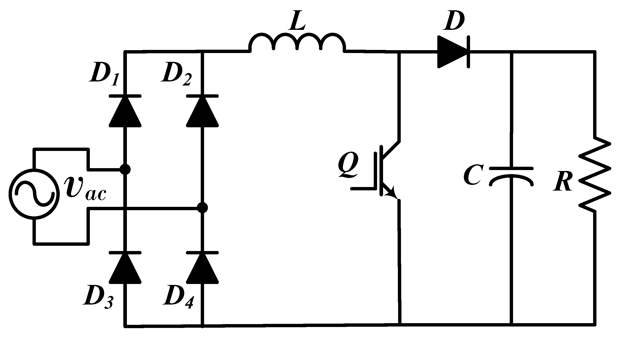
Figure 1. Conventional BBC topology with PFC.
Applsci 11 07651 g001
Figure 2. Conventional PFC topology with pseudo-continuous conduction.
Applsci 11 07651 g002
Figure 3. Interleaved PFC topology.
Applsci 11 07651 g003
Figure 4. Hybrid Interleaved PFC topology.
Applsci 11 07651 g004
Figure 5. Conventional PFC topology with a bidirectional switch.
Applsci 11 07651 g005
Figure 6. BBC converter with bidirectional switch: (a) bidirectional and flexible switches; (b) bidirectional and interleaved.
Applsci 11 07651 g006
Figure 7. Semi-bridgeless boost converter topology.
Applsci 11 07651 g007
Figure 8. Semi-bridgeless boost converter with soft switching.
Applsci 11 07651 g008
Figure 9. Semi-bridgeless boost converter with isolation.
Applsci 11 07651 g009
Figure 10. Semi-bridgeless boost converter with clamped diodes.
Applsci 11 07651 g010
Figure 11. Semi-bridgeless boost converter with clamped switches.
Applsci 11 07651 g011
Figure 12. Semi-bridgeless topology with clamped diodes and switches.
Applsci 11 07651 g012
Figure 13. Semi-bridgeless boost topology with clamped capacitors: (a) conventional; (b) coupling inductors.
Applsci 11 07651 g013
Figure 14. Semi-bridgeless topology with an internal snubber circuit.
Applsci 11 07651 g014
Figure 15. Conventional BBC or totem-pole converter: (a) line rectification with diodes; (b) line rectification with switches.
Applsci 11 07651 g015
Figure 16. Interleaved boost converter: (a) totem pole topology; (b) GaN totem-pole.
Applsci 11 07651 g016
Figure 17. Bridgeless boost converter pseudo totem-pole topology.
Applsci 11 07651 g017
Table 1. Summary and comparison among BBC, SBBC, and BLBC topologies categorized in this paper.
ConverterCategoryControlVoltagePowerSemi-
Conductors
Inductors+
Capacitors
BBCSBBCBLBCLinearNon-LinearLMLM
ConventionalX XXX X 62
Psudo continuousX XX X 82
InterleavedX XX XX 83
Hybrid interleavedX XXNot recommended104
BidirectionalX XX X 63
Bidirectionalflexible switchesX XNot recommended83
BidirectionalinterleavedX XNot recommended83
Conventional X XXX X 42
Soft switching X XXX X65
Isolation X XXX X 53
Clamped Diodes X XXX XX63
Clamped switches X XXX X 64
Clamped diodesand switches X XX X 83
Clamped capacitors X XXX X 45
Clamped capacitorscoupling inductors X XXX XX47
Zero voltage transition X XNot recommended115
Conventional XXXX X 42
Conventional GaN X XX XX42
Interleaved XXX XX 65
Interleaved GaN X X X X64
Pseudo totem-pole X XNot recommended63
Publisher’s Note: MDPI stays neutral with regard to jurisdictional claims in published maps and institutional affiliations.