
The Operation Analysis of the Innovative MainBox Food Storage Device


Abstract
:1. Introduction
2. Research Methods
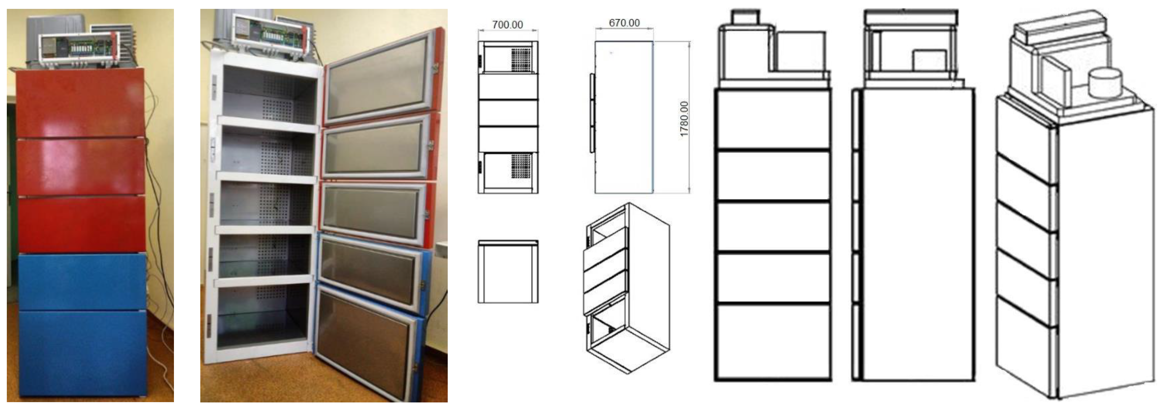
2.1. Test Stand
- -
- Constructional assumptions:
- -
- The rear wall of the MainBox had to be removable (service and maintenance requirements).
- -
- Leveling of thermal bridges with polyamide joints.
- -
- Optimization of installation sites for electronics and refrigeration in boxes and cutting out appropriate holes and securing them.
- -
- Requirements determination for explosion-proof electrical box. Optimal size and location behind the evaporator, among other things, in the electrical box had to fit additional controllers, relays.
- -
- Temperature monitoring assumptions:
- -
- Placement of temperature sensors at the outlet was planned to control the performance of the cool system. If the temperature was not low enough: possibility to activate controlled forced cooling.
- -
- Optimization of the temperature sensor placement was carried out including additional temperature gauges to monitor and record the temperature on each shelf.
- -
- Equipment operation assumptions:
- -
- The use of a defrost heater to heat the cold box in the winter.
- -
- The air inlet and outlet places on the shelves were planned to be located—air blades allowing for regulation of the air inlet in the side wall. Implementation of the air controllers with insulating material (styrodur).
- -
- Smart wire to the door to prevent freezing of the door seal.
- 1.
- The MainBox used compact air cooling devices (monoblock) with the necessary certification provided by the manufacturer. A refrigeration unit designed for indoor refrigeration furniture was used to work in outdoor conditions, which forced the use of additional elements in the refrigeration unit itself, which were not normally installed:
- -
- High and low pressure compressor protection pressure switches.
- -
- High pressure switch to control the condensing pressure by switching the condenser fan on and off (necessary at low outdoor temperature).
- 2.
- The temperature in cooling chambers was ensured by blowing cold air which, after being heated in the chambers, went back through the ventilation duct to the cooling device located above the chambers and was cooled in the evaporator. The heat removed from the air was disposed of in a condenser cooled by external air.
- 3.
- Due to the fact that, in the chambers, a temperature of +5 °C had to be ensured and the whole system will operate at outdoor temperatures from −20 °C to +35 °C, an additional electric heater was used:
- -
- An additional electric heater on the evaporator with a power of 400 W, which, in combination with the standard defrosting heater with a power of 230 W, ensured heating of the chambers at negative outside temperatures. Both heaters were controlled by a thermostat located in the electrical box based on the temperature reading of the air returning to the refrigeration unit.
- -
- Temperature control in individual boxes was correlated with the return air temperature to the chiller, because the air returned to the chiller through a common return duct. This was averaged over all boxes. Based on this temperature reading, the module’s local controller turned the chiller on and off. Temperature sensors have been installed at all air outlets from the boxes to prevent a temperature rise in individual boxes. If the return air temperature from any box exceeded the upper setpoint, then the master controller forced the cooling of the entire module regardless of the temperature reading in the common return duct. Once the temperature was reduced to the setpoint, the master controller removed the forced chiller operation signal and the unit returned to local controller operation based on the return air temperature.
- -
- Adequate circulation of cooled air was ensured by the appropriate amount of cooled air flowing into individual boxes to obtain the same temperature in each of the return air streams with an accuracy of ±1 °C.
- -
- In order to eliminate the risk of the door freezing to the casing due to the appearance of water or frost on its edge, an appropriate heating installation was installed in the place of door contact.
- 4.
- The refrigeration unit was filled with the natural refrigerant (propane—R290), due to its following advantages over typical synthetic refrigerants such as R134a, R452a, and R404a:
- -
- GWP—greenhouse effect potential for propane is 3, where for R134a it is = 1430, for R452a = 2141, and for R404a = 3922.
- -
- High energy efficiency (lower energy consumption with similar cooling capacity)—for a cooling capacity of 434 W (evaporation −10 °C and condensation +50 °C), the electrical power of the unit with propane is 154 W—for R134a, it is 208 W (efficiency 457 W), and for R452a, it is 239 W (efficiency 467 W).
- 5.
- Propane flammability is the disadvantage, but this problem has been eliminated by:
- -
- Using the propane advantage of a high specific mass cooling capacity of 290 kJ/kg and for which the amount of refrigerant in the system was only 90 g (this exempted fire protection)—for R134a, it was 150 kJ/kg and 240 g.
- -
- Hermetically sealing the refrigeration system. This meant that all connections were soldered. The system did not have a service valve for possible refrigerant recovery and filling in case of repair work. The service pipe was clamped and also soldered. Special tools must be used for repair work.
- 6.
- The unit complies with fire and safety regulations. This solution increased fire safety in the event of a refrigerant leak. It also prevented the refrigerant from accumulating in one place, because the density of propane is higher than that of air. The boxes were cooled down by blowing the cooled air from the evaporator through a ventilation duct located at the rear of the module and through air supply openings in the rear walls of the boxes, while the side walls of the boxes were equipped with air deflectors.
- 7.
- The doors of individual boxes were opened by lifting the lock of the door of a given box after reading the correct code provided by the supplier or recipient of goods. Door opening should last as short as possible. For this purpose, the module was equipped with a door opening sound signal, which reminded the person opening the door that it was not closed. After a specified time (e.g., 15 s), the intensity of this signal changed. If the door still did not close, the technical service was notified.
2.2. Testing Temperatures in Prototype Equipment
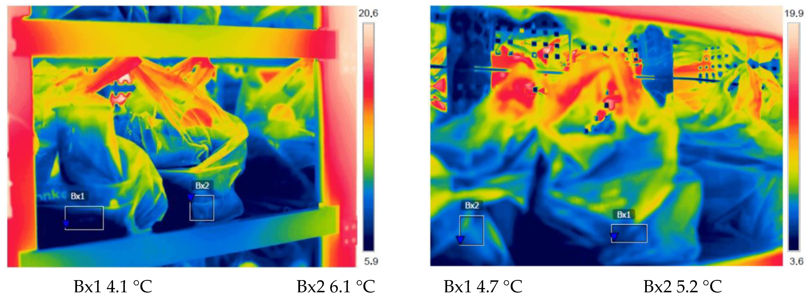
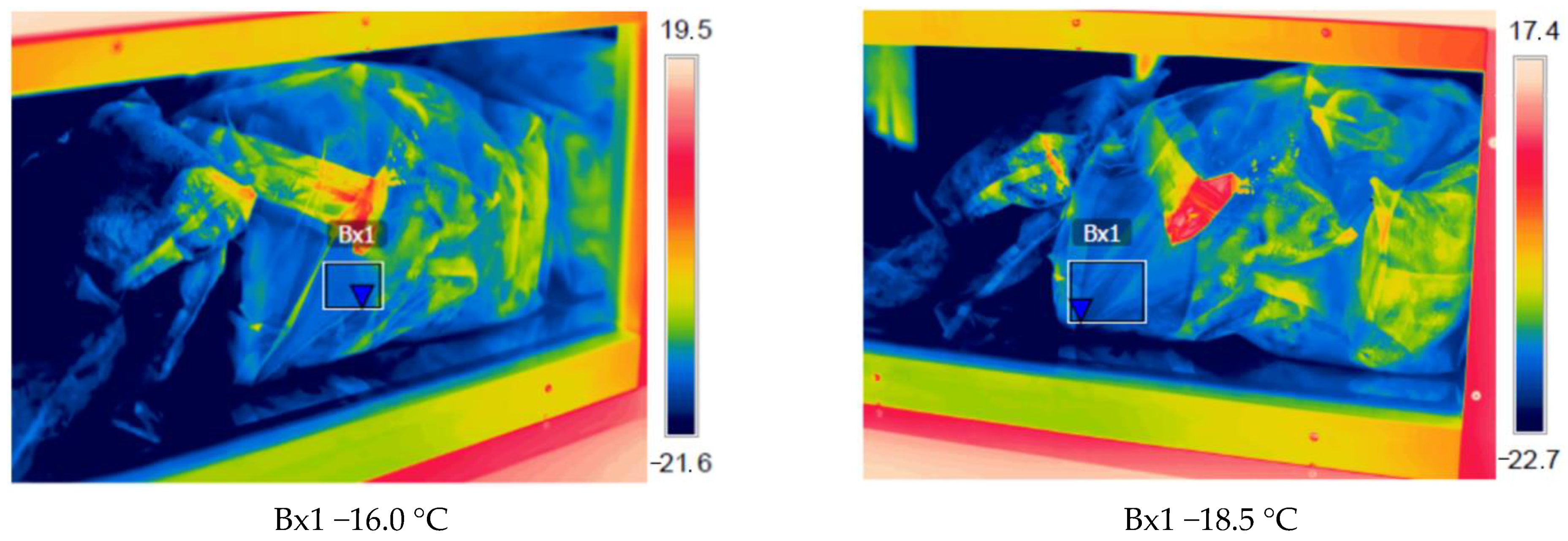
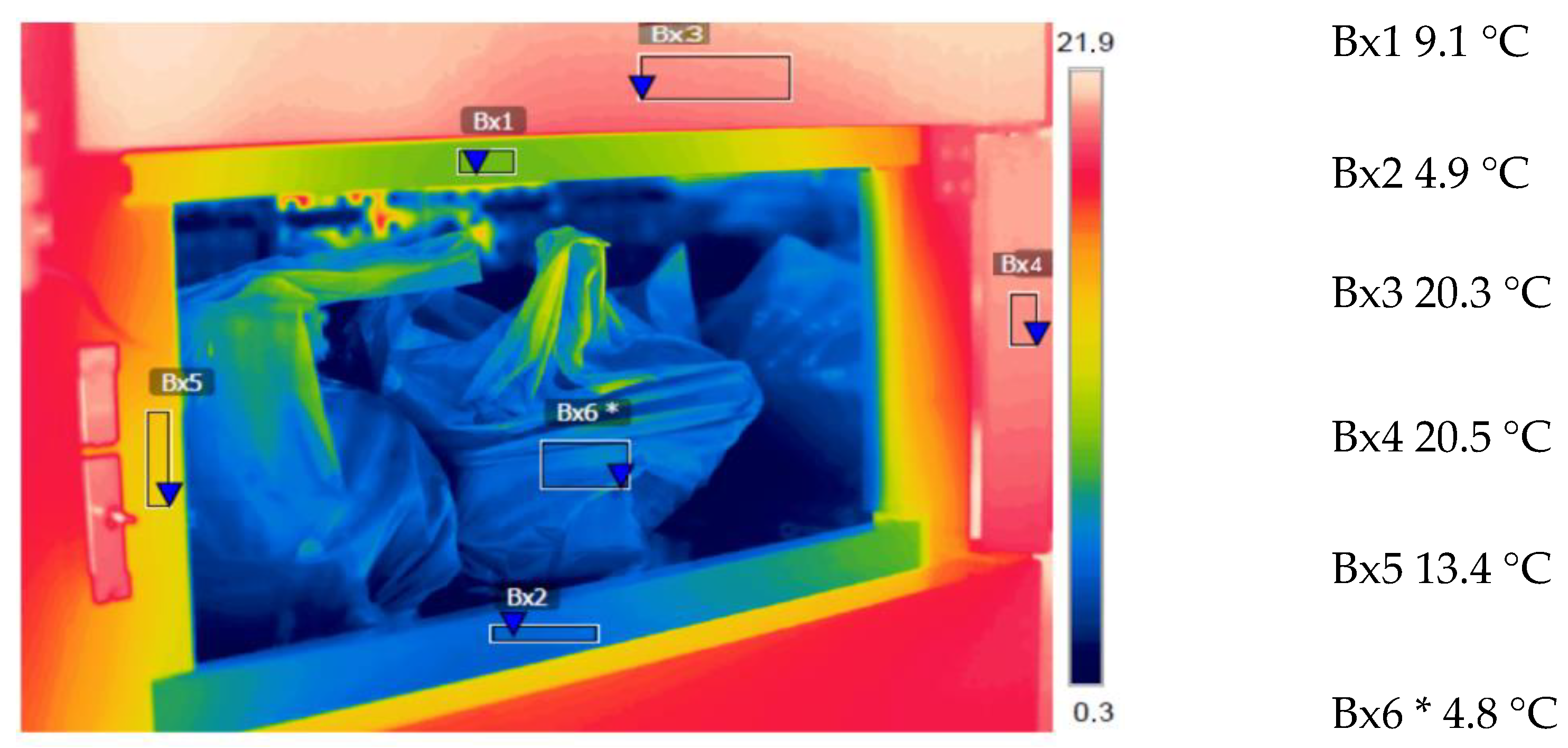
2.3. Thermal Imaging Tests on Prototype Devices
2.4. Refrigerant Characteristics
- -
- For a 298 W cooling module, at the following temperatures: evaporation −5 °C, chamber +2 °C, and ambient +40 °C.
- -
- For the 410 W freezing module, at the following temperatures: evaporation −25 °C, chamber −18 °C, and ambient +40 °C.
3. Results and Discussion
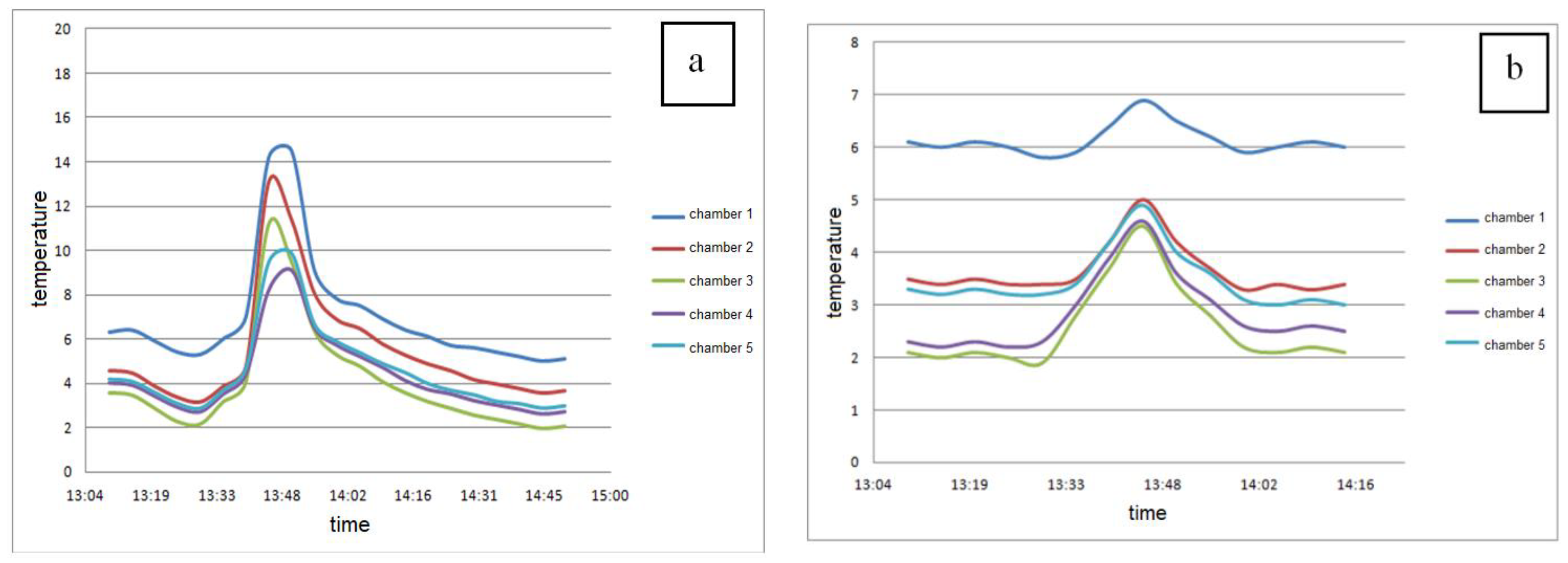
3.1. Temperature Monitoring of Prototype Equipment
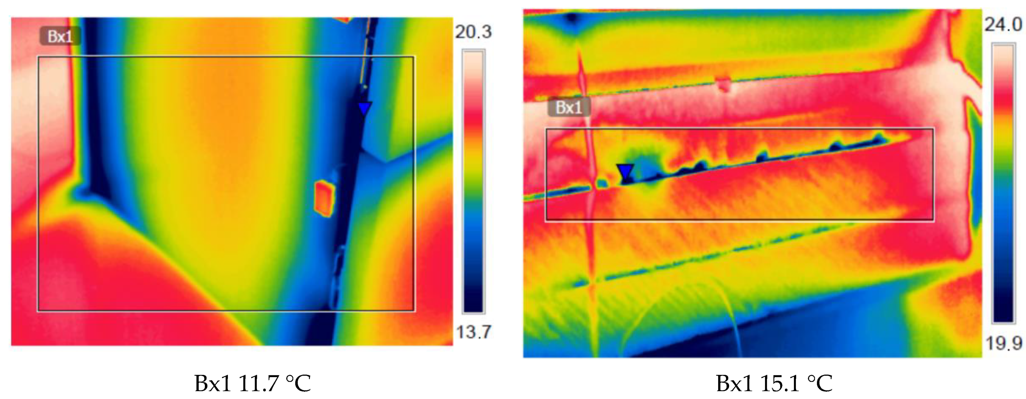
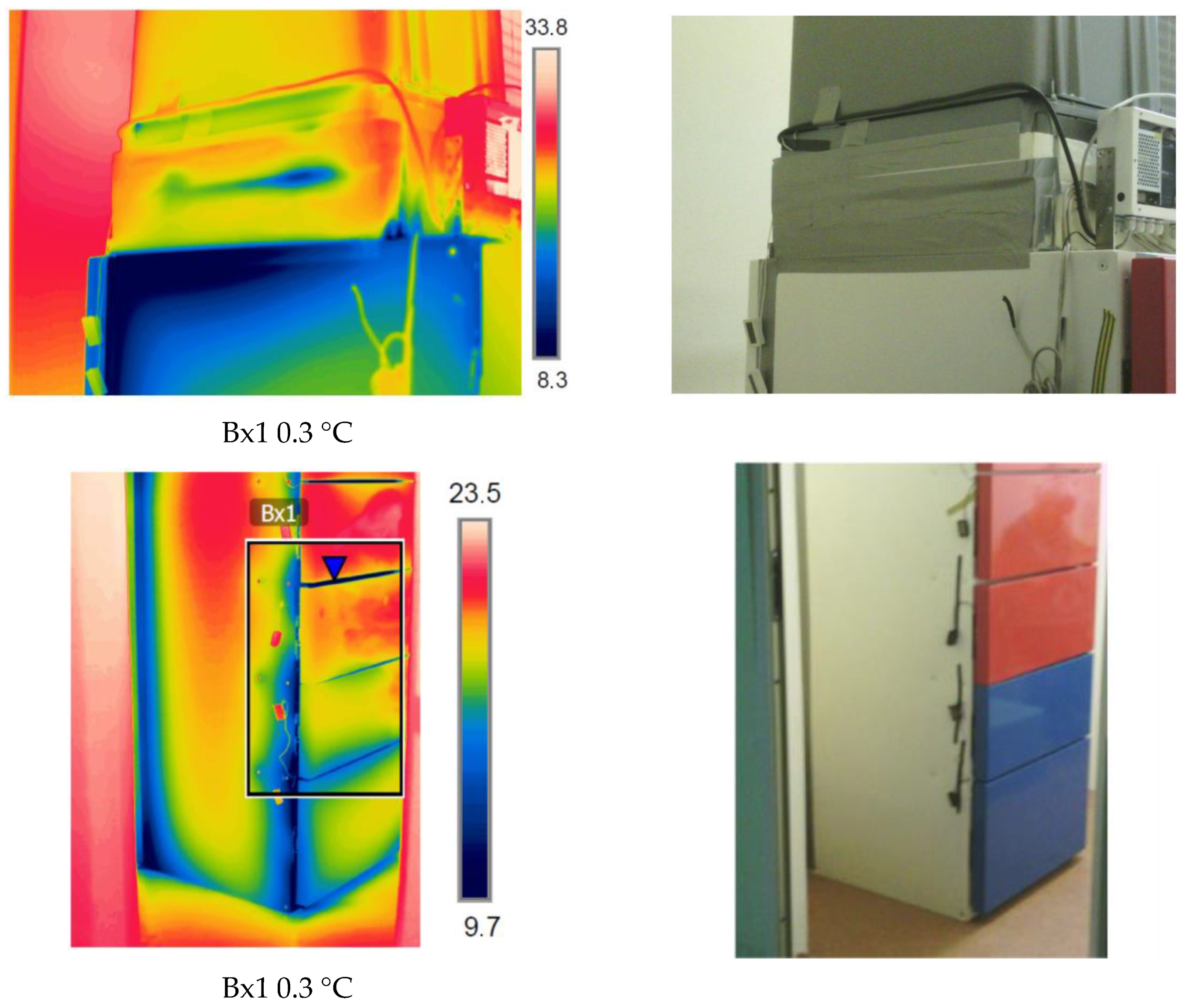
3.2. Tightness Monitoring of Prototype Cooling Chambers
- -
- Structure leakage—chamber door side wall of the module, causing thermal bridges and insulation leakage between the module and the monoblock (see minimum point Bx1 on Figure 12),
- -
- Thermal bridges on the side wall of the module and insulation leakage between the module and the monoblock (see minimum point Bx1 on Figure 13).
4. Conclusions
- -
- The refrigeration unit was adapted to work in external conditions by installing additional elements (pressure switches for protecting compressor, pressure switch for condensing pressure control).
- -
- Temperature control in individual boxes correlated with temperature of return air to cooling unit was designed and heating of chambers was ensured.
- -
- Optimum access to the boxes was ensured.
- -
- Propane as a natural refrigerant was used (high energy efficiency, low GWP), eliminating its amount and sealing the device, thus reducing the risk of explosion (the device met the requirements of fire and safety regulations).
5. Patent
Author Contributions
Funding
Institutional Review Board Statement
Informed Consent Statement
Data Availability Statement
Conflicts of Interest
References
- Formoso, G.; Pipino, C.; Baldassarre, M.P.A.; Del Boccio, P.; Zucchelli, M.; D’Alessandro, N.; Tonucci, L.; Cichelli, A.; Pandolfi, A.; Di Pietro, N. An Italian innovative small-scale approach to promote the conscious consumption of healthy food. Appl. Sci. 2020, 10, 5678. [Google Scholar] [CrossRef]
- Evansa, K.S.; Teisl, M.F.; Lando, A.M.; Liu, S.T. Risk perceptions and food-handling practices in the home. Food Policy 2020, 95, 101939. [Google Scholar] [CrossRef]
- Zhang, X.; Lam, J.S.L.; Iris, Ç. Cold chain shipping mode choice with environmental and financial perspectives. Transp. Res. Part D Transp. Environ. 2020, 87, 102537. [Google Scholar] [CrossRef]
- Sarkar, B.; Omair, M.; Choi, S.-B. A multi-objective optimization of energy, economic, and carbon emission in a production model under sustainable supply chain management. Appl. Sci. 2018, 8, 1744. [Google Scholar] [CrossRef] [Green Version]
- Carson, J.K.; East, A.R. The cold chain in New Zealand—A review. Int. J. Refrig. 2018, 87, 185–192. [Google Scholar] [CrossRef]
- Talbot, L.; Purnell, G.; James, S.J.; James, C. Operating temperatures of supermarket frozen retail display cabinets. Int. J. Refrig. 2020, 117, 81–93. [Google Scholar] [CrossRef]
- Kiba-Janiak, M.; Marcinkowski, J.; Jagoda, A.; Skowrońska, A. Sustainable last mile delivery on e-commerce market in cities from the perspective of various stakeholders. Literature review. Sustain. Cities Soc. 2021, 71, 102984. [Google Scholar] [CrossRef]
- Bjørgen, A.; Bjerkan, K.Y.; Hjelkrem, O.A. E-groceries: Sustainable last mile distribution in city planning. Res. Transp. Econ. 2021, 87, 100805. [Google Scholar] [CrossRef]
- Janjevic, M.; Winkenbach, M. Characterizing urban last-mile distribution strategies in mature and emerging e-commerce markets. Transp. Res. Part A Policy Pract. 2020, 133, 164–196. [Google Scholar] [CrossRef]
- Yuen, K.F.; Wang, X.; Ma, F.; Wong, Y.D. The determinants of customers’ intention to use smart lockers for last-mile deliveries. J. Retail. Consum. Serv. 2019, 49, 316–326. [Google Scholar] [CrossRef]
- Wu, J.-Y.; Hsiao, H.-I. Food quality and safety risk diagnosis in the food cold chain through failure mode and effect analysis. Food Control 2021, 120, 107501. [Google Scholar] [CrossRef]
- Lemardele, C.; Estrada, M.; Pages, L.; Bachofner, M. Potentialities of drones and ground autonomous delivery devices for last-mile logistics. Transp. Res. Part E Logist. Transp. Rev. 2021, 149, 102325. [Google Scholar] [CrossRef]
- Srinivas, S.S.; Marathe, R.R. Moving towards “mobile warehouse”: Last-mile logistics during COVID-19 and beyond. Transp. Res. Interdisc. Persp. 2021, 10, 100339. [Google Scholar]
- Leng, L.; Zhang, J.; Zhang, C.; Zhao, Y.; Wang, W.; Li, G. Decomposition-based hyperheuristic approaches for the bi-objective cold chain considering environmental effects. Comput. Oper. Res. 2020, 123, 105043. [Google Scholar] [CrossRef]
- Castillo-González, E.; Giraldi-Díaz, M.R.; De Medina-Salas, L.; De la Cruz, R.V. Environmental Impacts associated to different stages spanning from harvesting to industrialization of pineapple through life cycle assessment. Appl. Sci. 2020, 10, 7007. [Google Scholar] [CrossRef]
- Varotsos, C.A.; Tzanis, C. A new tool for the study of the ozone hole dynamics over Antarctica. Atmos. Environ. 2012, 47, 428–434. [Google Scholar] [CrossRef]
- Basalirwa, D.; Sudo, S.; Wacal, C.; Namirembe, C.; Sasagawa, D.; Yamamoto, S.; Masunaga, T.; Nishihara, E. Effect of activated carbon on greenhouse gas emissions, seed yield, soil chemical properties and isoflavone content of soybean genotypes with varying nodulation capacities under sandy soil conditions. Rhizosphere 2020, 14, 100202. [Google Scholar] [CrossRef]
- Wang, X.; Li, M.; Cai, L.; Li, Y. Propane and iso-butane pre-cooled mixed refrigerant liquefaction process for small-scale skid-mounted natural gas liquefaction. Appl. Energy 2020, 275, 115333. [Google Scholar] [CrossRef]
- Mazyan, W.I.; Ahmadi, A.; Ahmed, H.; Hoorfar, M. Increasing the COP of a refrigeration cycle in natural gas liquefaction process using refrigerant blends of Propane-NH3, Propane-SO2 and Propane-CO2. Heliyon 2020, 6, e04750. [Google Scholar] [CrossRef] [PubMed]
- Righetti, G.; Zilio, C.; Longo, G.A. Comparative performance analysis of the low GWP refrigerants HFO1234yf, HFO1234ze(E) and HC600a inside a roll-bond evaporator. Int. J. Refrig. 2015, 54, 1–9. [Google Scholar] [CrossRef]
- Harby, K. Hydrocarbons and their mixtures as alternatives to environmental unfriendly halogenated refrigerants: An updated overview. Renew. Sustain. Energy Rev. 2017, 73, 1247–1264. [Google Scholar] [CrossRef]
- Adelekan, D.S.; Ohunakin, O.S.; Gill, J.; Atiba, O.E.; Okokpujie, I.P.; Atayero, A.A. Performance of a domestic refrigerator infused with safe charge of R600a refrigerant and various concentrations of TiO2 nanolubricants. Procedia Manuf. 2019, 35, 1158–1164. [Google Scholar] [CrossRef]
- Pilla, T.S.; Sunkari, P.K.G.; Padmanabhuni, S.L.; Nair, S.S.; Dondapati, R.S. Experimental evaluation mechanical performance of the compressor with mixed refrigerants R-290 and R-600a. Energy Procedia 2017, 109, 113–121. [Google Scholar] [CrossRef]
- Sperling, L.; Louwaars, N.; Ponti, O.; Smale, M.; Baributsa, D.; Etten, J. Viewpoint: COVID-19 and seed security response now and beyond. Food Policy 2020, 97, 102000. [Google Scholar] [CrossRef]
- Paurine, A.; Maidment, G.G.; Rodway, M.; Yebiyo, M. Understanding the market need for skills in alternative refrigerants with low global warming potential in the EU region—A comprehensive survey on Refrigerant Emissions and Leakage (REAL) alternatives programme. Int. J. Refrig. 2021, 122, 11–20. [Google Scholar] [CrossRef]
- Marco-Fondevila, M.; Moneva, J.M.; Llena-Macarulla, F. Accounting for carbon footprint flows in wine production process. Case study in Spanish winery. Appl. Sci. 2020, 10, 8381. [Google Scholar] [CrossRef]
- Wróbel-Jędrzejewska, M.; Stęplewska, U.; Włodarczyk, E.; Polak, E. Determination of the emissivity factor under cooling conditions in the agri-food industry. Post. Nauk. Tech. Przem. Rol-Spoż. 2020, 1, 32. [Google Scholar]
- Regulation (EU) No 517/2014 of the European Parliament and of the Council of 16 April 2014 on Fluorinated Greenhouse Gases and Repealing Regulation (EC) No 842/2006. Available online: https://eur-lex.europa.eu/legal-content/EN/TXT/PDF/?uri=CELEX:32014R0517&rid=1 (accessed on 1 February 2021).
- Heredia-Aricapa, Y.; Belman-Flores, J.M.; Mota-Babiloni, A.; Serrano-Arellano, J.; García-Pabón, J.J. Overview of low GWP mixtures for the replacement of HFC refrigerants: R134a, R404A and R410A. Int. J. Refrig. 2020, 111, 113–123. [Google Scholar] [CrossRef]
- Colbourne, D.; Suenb, K.O.; Li, T.-X.; Vince, I.; Vonsil, A. General framework for revising class A3 refrigerant charge limits—A discussion. Int. J. Refrig. 2020, 117, 209–217. [Google Scholar] [CrossRef]
- Weather Online. Available online: www.weatheronline.pl (accessed on 1 February 2021).


| Chamber/Box No. | Cooling Module (°C) | Freezing Module (°C) |
|---|---|---|
| min ÷ max | ||
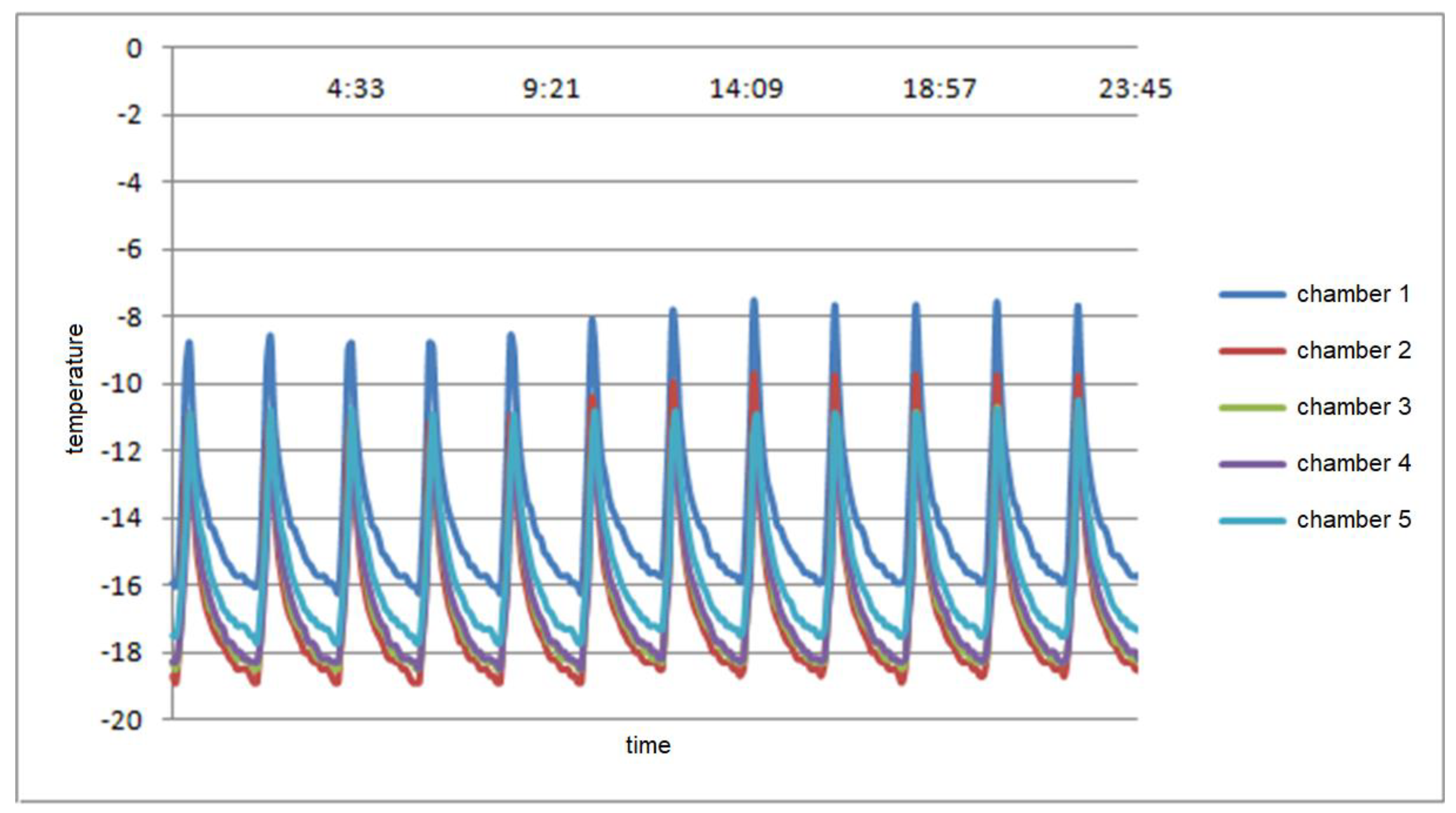
| 1 | 6.0 ÷ 7.4 | −16.4 ÷ −14.4 |
| 2 | 3.1 ÷ 6.9 | −19.5 ÷ −16.5 |
| 3 | 1.8 ÷ 4.9 | −19.0 ÷ −16.0 |
| 4 | 2.6 ÷ 5.8 | −18.0 ÷ −13.7 |
| 5 | 2.4 ÷ 6.1 | −17.7 ÷ −16.0 |
| Chamber/Box No. | Temperature Inside the Empty Box (°C) | Temperature Inside the Box Immediately after Loading with the Products (°C) |
|---|---|---|
| 1 | 7.9 | 11.2 |
| 2 | 5.4 | 8.6 |
| 3 | 4.6 | 7.8 |
| 4 | 5.6 | 9.3 |
| 5 | 5.6 | 9.5 |
| Chamber/Box No. | Temperature Inside the Empty box (°C) | Temperature Inside the Box Immediately after Loading with the Products (°C) |
|---|---|---|
| 1 | −16.4 | −14.4 |
| 2 | −19.5 | −16.5 |
| 3 | −19.0 | −16.0 |
| 4 | −18.0 | −13.7 |
| 5 | −17.7 | −16.0 |
Publisher’s Note: MDPI stays neutral with regard to jurisdictional claims in published maps and institutional affiliations. |
© 2021 by the authors. Licensee MDPI, Basel, Switzerland. This article is an open access article distributed under the terms and conditions of the Creative Commons Attribution (CC BY) license (https://creativecommons.org/licenses/by/4.0/).
Share and Cite
Wróbel-Jędrzejewska, M.; Polak, E. The Operation Analysis of the Innovative MainBox Food Storage Device. Appl. Sci. 2021, 11, 7682. https://doi.org/10.3390/app11167682
Wróbel-Jędrzejewska M, Polak E. The Operation Analysis of the Innovative MainBox Food Storage Device. Applied Sciences. 2021; 11(16):7682. https://doi.org/10.3390/app11167682
Chicago/Turabian StyleWróbel-Jędrzejewska, Magdalena, and Elżbieta Polak. 2021. "The Operation Analysis of the Innovative MainBox Food Storage Device" Applied Sciences 11, no. 16: 7682. https://doi.org/10.3390/app11167682