
On the Impact of Additive Manufacturing Processes Complexity on Modelling


Abstract
:1. Introduction
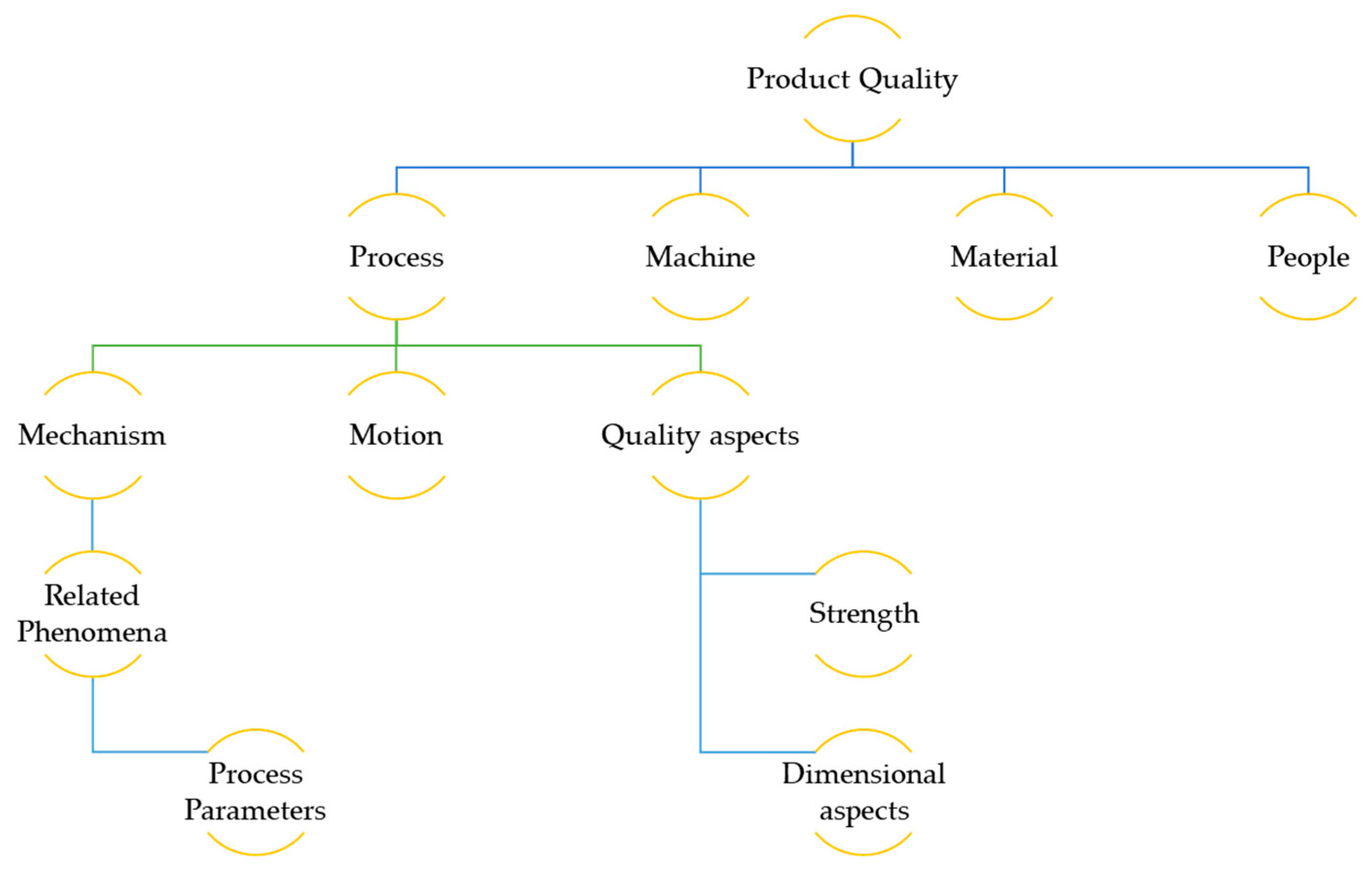
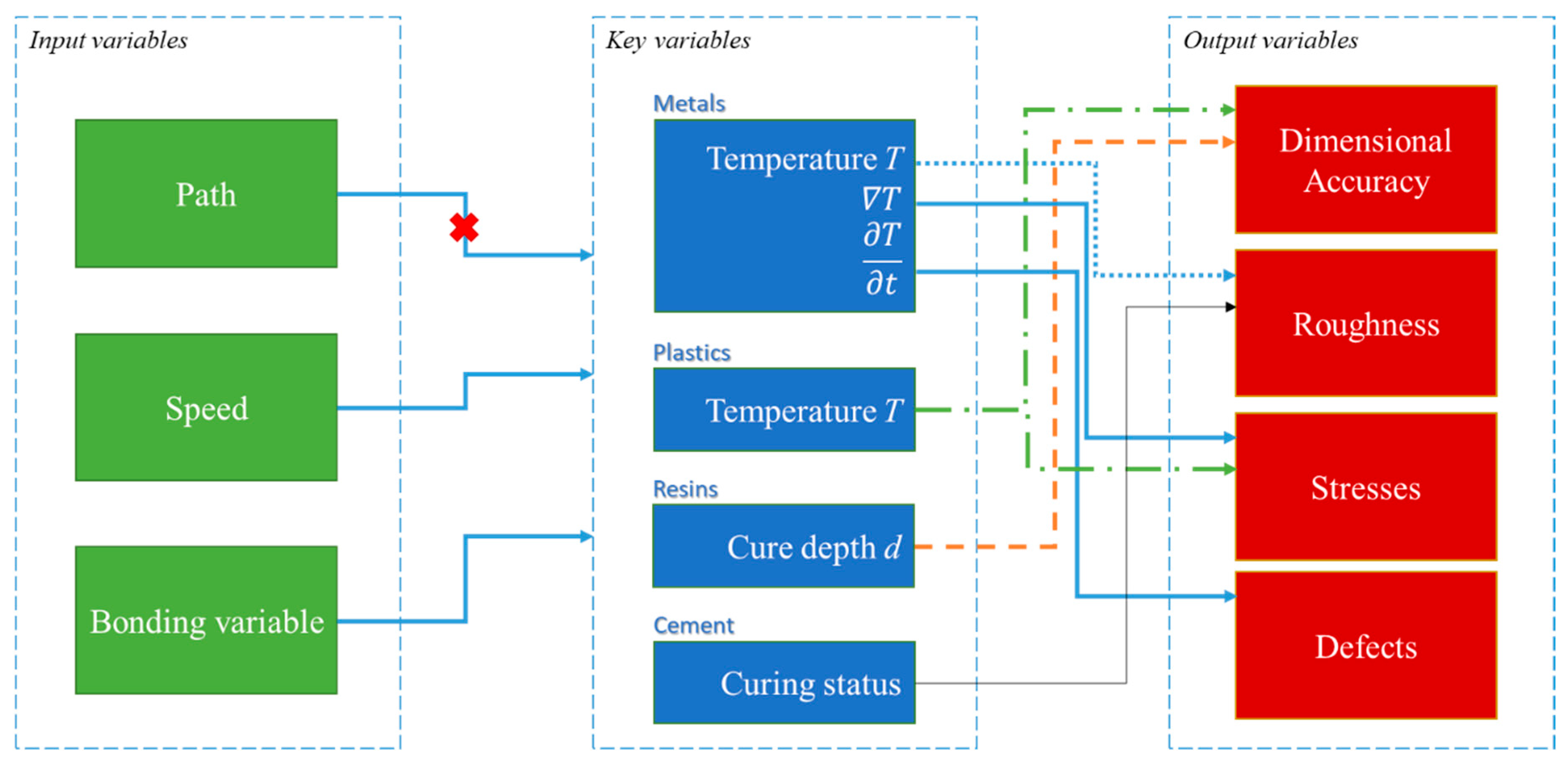
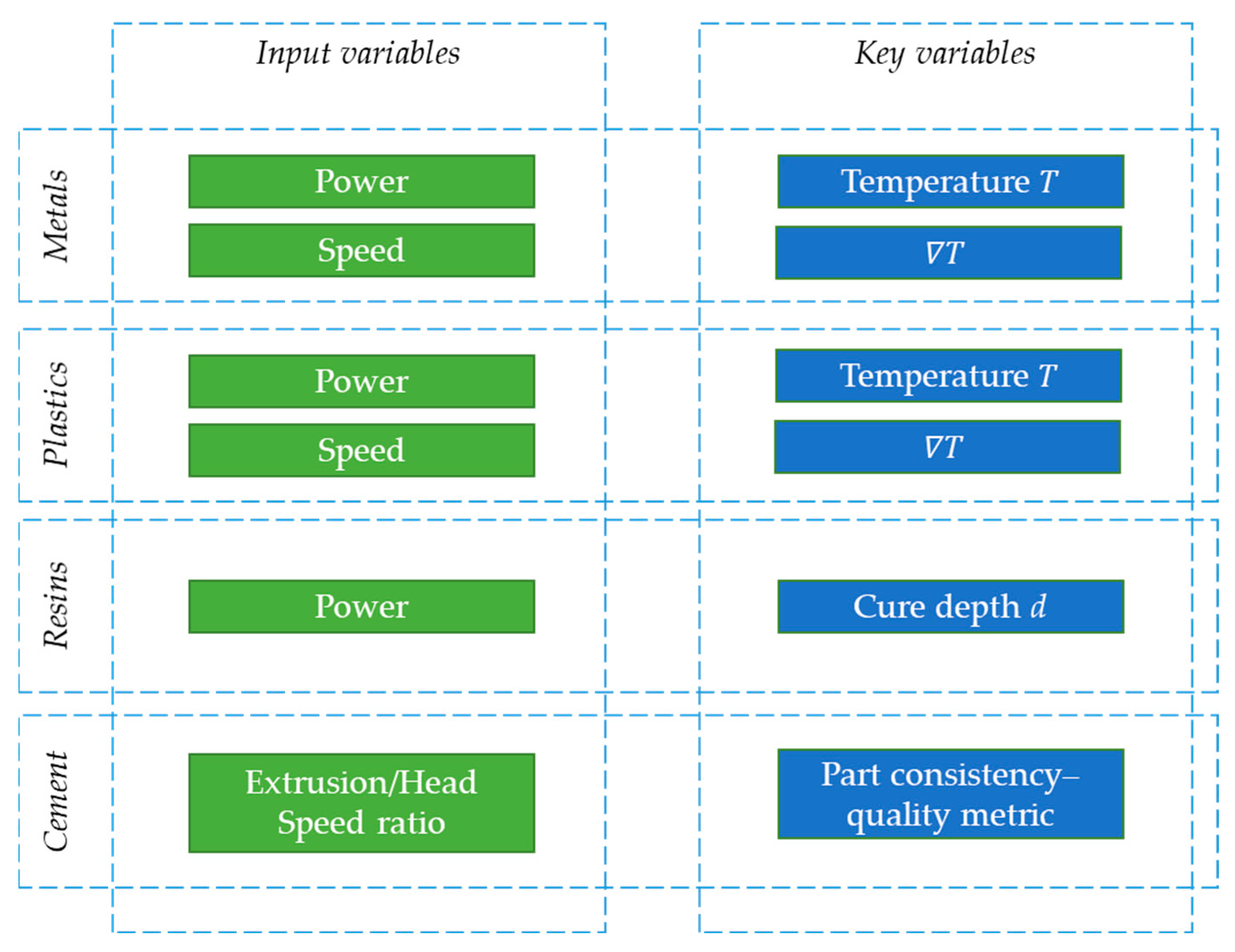
2. Framework
- Algebraic systems f(xn) = 0: number of variables n, form of equations f, solvability.
- Dynamic systems f(xn’,xn) = 0: number of variables, order of derivatives, form of equations, solvability
- Distributed systems f(,xn) = 0: number of variables, number of independent variables, order of derivatives, form of equations, solvability
- Control problems f(,xn,um) = 0: number of variables, number of independent variables (u), order of derivatives, number of inputs, form of equations, solvability, controllability
- I = log(KMNQU)
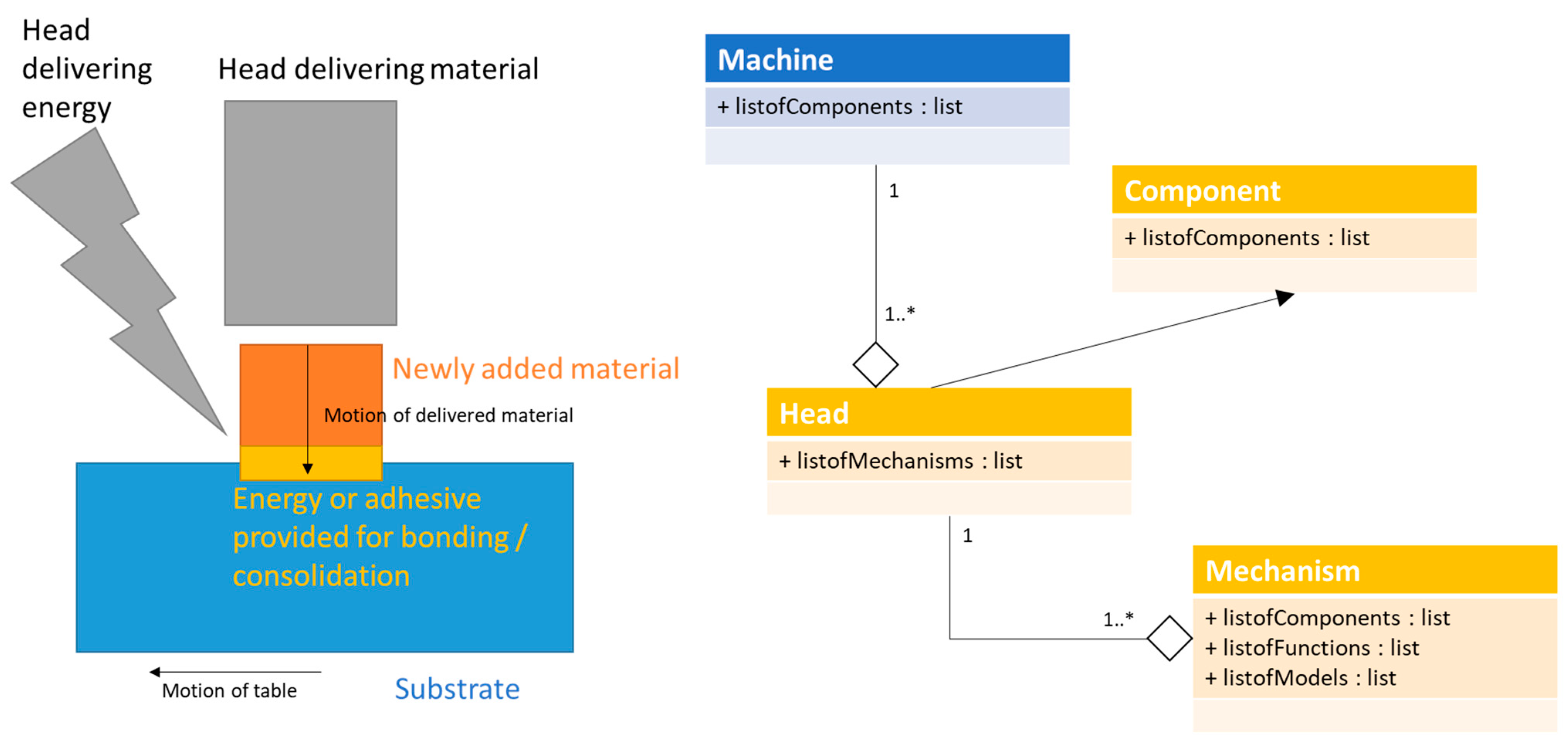
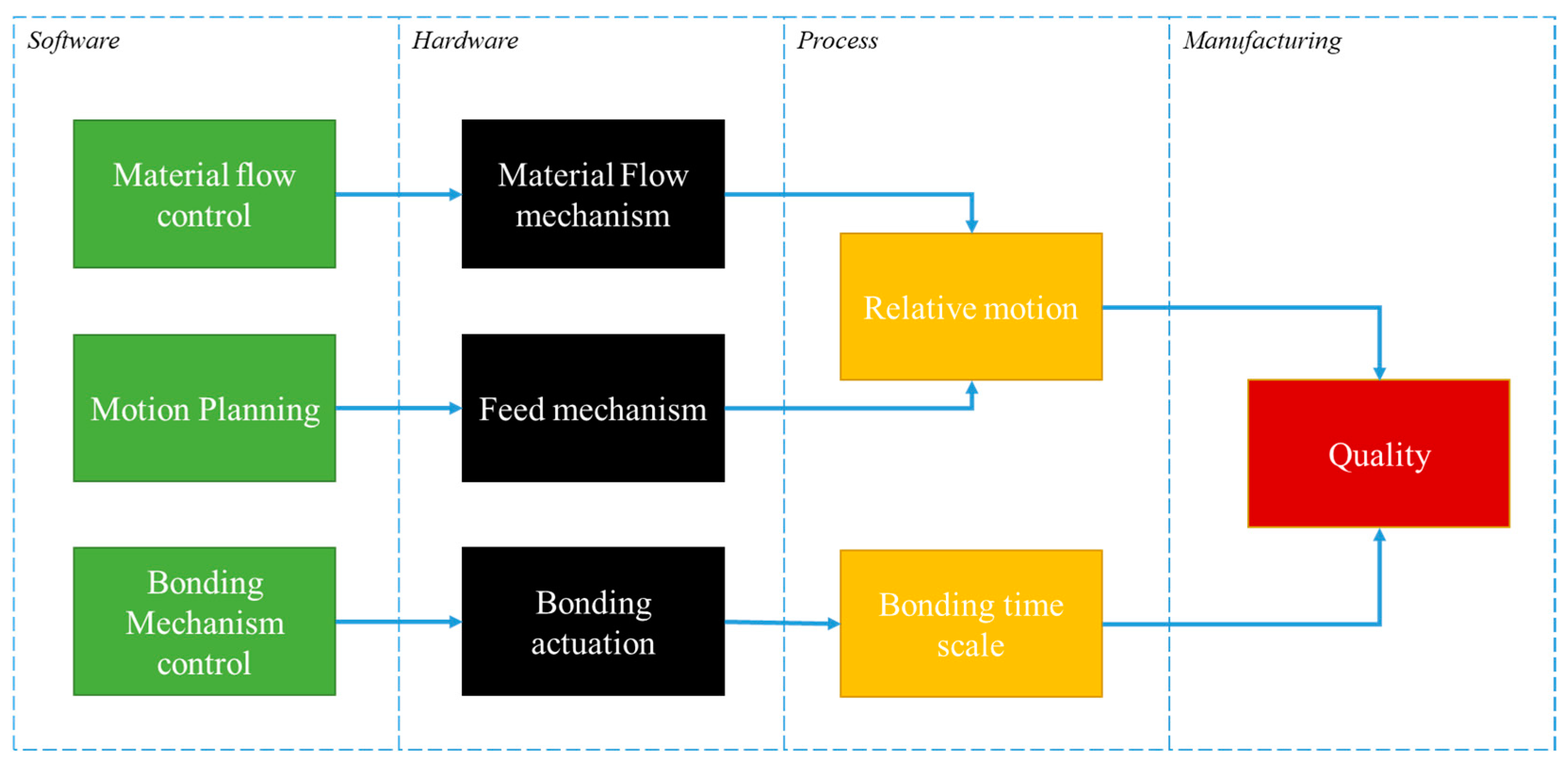
- Software, including a form of input to the process.
- Hardware, specifying what is being affected directly by the corresponding software.
- The process characteristic, which mainly consists of motion and bonding; the latter is depending on the process that this procedure is applied on, so candidates underlying mechanisms may be solidification (i.e., in SLM) and polymerization (i.e., in SLM).
- Manufacturing, containing the corresponding KPIs (that is quality, in the context of the current work).
- The complexity is an additive metric, thus it should engage logarithms, as in the case of Shannon’s entropy [79].
- Discrete values for each variable are considered. This is a way to ease the computation of the complexity.
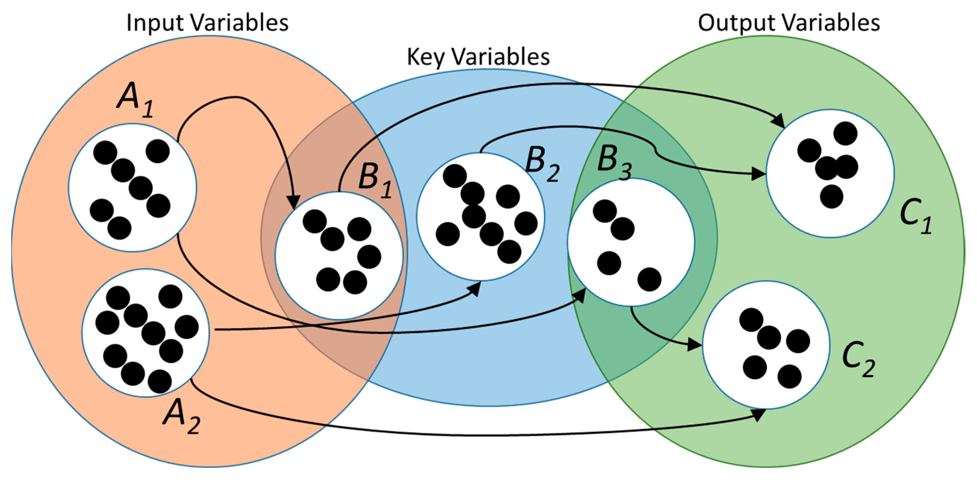
- The size of the search space (combined process parameters (PPs) and key performance indicators (KPIs) space) in a control or an optimization problem is indicative of its complexity.
- Laser frequency is neglected as pulsed laser could be considered continuous with reduced power, under specific conditions.
- Speed is considered to be a control variable, in the sense that it controls the process time and the bonding variable compensates for its effect.
- All issues related to post-processing are neglected.
- Path effect can be represented by the gradient of the temperature. This reduces to a high extent the formulation, as path itself is not an easily quantifiable factor.
3. Implementation and Primary Results
4. Discussion
4.1. Classification of Processes
4.2. Connection to Modelling Procedure
4.3. Subjectivity and Limitations of the Heuristic Entropic Metric
5. Conclusions
- Development of process models for the increase in AM part quality;
- Consideration and investigation of the effect of the head movement on part quality (path and speed);
- Increase in the practicality of simulations for AM;
- Enabling the practical evaluation of alternatives to achieve higher part quality;
- Achieving the simulation of the entire process time.
Author Contributions
Funding
Institutional Review Board Statement
Informed Consent Statement
Data Availability Statement
Conflicts of Interest
References
- Chryssolouris, G. Manufacturing Systems: Theory and Practice, 2nd ed.; Springer: New York, NY, USA, 2006; ISBN 0387256830. [Google Scholar]
- Saptarshi, S.M.; Zhou, C. Basics of 3D printing: Engineering aspects. 3D Print. Orthop. Surg. 2019, 17–30. [Google Scholar] [CrossRef]
- Levy, G.N.; Schindel, R.; Kruth, J.P. Rapid manufacturing and rapid tooling with layer manufacturing (LM) technologies, state of the art and future perspectives. CIRP Ann. 2003, 52, 589–609. [Google Scholar] [CrossRef]
- Hopkinson, N.; Hague, R.J.M.; Dickens, P.M. Rapid Manufacturing: An Industrial Revolution for the Digital Age; John Wiley & Sons, Ltd.: Chichester, UK, 2005; ISBN 9780470033999. [Google Scholar]
- Marga, F.; Jakab, K.; Khatiwala, C.; Shepherd, B.; Dorfman, S.; Hubbard, B.; Colbert, S.; Gabor, F. Toward engineering functional organ modules by additive manufacturing. Biofabrication 2012, 4, 22001. [Google Scholar] [CrossRef]
- Bikas, H.; Lianos, A.; Stavropoulos, P. A design framework for additive manufacturing. Int. J. Adv. Manuf. Technol. 2019, 103, 3769–3783. [Google Scholar] [CrossRef] [Green Version]
- Wohlers, T.T.; Caffrey, T. Wohlers Report 2015: 3D Printing and Additive Manufacturing State of the Industry Annual Worldwide Progress Report; Wohlers Associates: Fort Collins, CO, USA, 2015; ISBN 0991333217. [Google Scholar]
- Thomas, D. Costs, benefits, and adoption of additive manufacturing: A supply chain perspective. Int. J. Adv. Manuf. Technol. 2016, 85, 1857–1876. [Google Scholar] [CrossRef] [PubMed] [Green Version]
- Bikas, H.; Stavropoulos, P.; Chryssolouris, G. Additive manufacturing methods and modelling approaches: A critical review. Int. J. Adv. Manuf. Technol. 2015, 83, 389–405. [Google Scholar] [CrossRef] [Green Version]
- Stavropoulos, P.; Papacharalampopoulos, A.; Michail, C.; Vassilopoulos, V.; Alexopoulos, K.; Perlo, P. A two-stage decision support system for manufacturing processes integration in microfactories for electric vehicles. Procedia Manuf. 2021, 54, 106–111. [Google Scholar] [CrossRef]
- Chan, S.L.; Lu, Y.; Wang, Y. Data-driven cost estimation for additive manufacturing in cybermanufacturing. J. Manuf. Syst. 2018, 46, 115–126. [Google Scholar] [CrossRef]
- Adam, G.; Zimmer, D. Design for Additive Manufacturing—Element transitions and aggregated structures. CIRP J. Manuf. Sci. Technol. 2014, 7, 20–28. [Google Scholar] [CrossRef]
- Levy, G.N. The role and future of the Laser Technology in the Additive Manufacturing environment. Phys. Procedia 2010, 5, 65–80. [Google Scholar] [CrossRef] [Green Version]
- ISO/ASTM52900-15. Standard Terminology for Additive Manufacturing—General Principles—Terminology; ASTM International: West Conshohocken, PA, USA, 2015. [Google Scholar]
- Hegab, H. Design for additive manufacturing of composite materials and potential alloys: A review. Manuf. Rev. 2016, 3, 11. [Google Scholar] [CrossRef] [Green Version]
- Bartolo, P.; Kruth, J.-P.; Silva, J.; Levy, G.; Malshe, A.; Rajurkar, K.; Mitsuishi, M.; Ciurana, J.; Leu, M. Biomedical production of implants by additive electro-chemical and physical processes. CIRP Ann. 2012, 61, 635–655. [Google Scholar] [CrossRef]
- Gibson, I.; Rosen, D.W.; Stucker, B. Additive Manufacturing Technologies; Springer US: Boston, MA, USA, 2010; ISBN 9781441911193. [Google Scholar]
- Stavropoulos, P.; Foteinopoulos, P. Modelling of additive manufacturing processes: A review and classification. Manuf. Rev. 2018, 5, 2. [Google Scholar] [CrossRef] [Green Version]
- Kempen, K.; Vrancken, B.; Buls, S.; Thijs, L.; van Humbeeck, J.; Kruth, J.-P. Selective Laser Melting of Crack-Free High Density M2 High Speed Steel Parts by Baseplate Preheating. J. Manuf. Sci. Eng. 2014, 136, 061026. [Google Scholar] [CrossRef]
- Flatt, R.J.; Wangler, T. Editorial for special issue on digital concrete. Cem. Concr. Res. 2018, 112, 1–4. [Google Scholar] [CrossRef]
- Foteinopoulos, P.; Esnault, V.; Komineas, G.; Papacharalampopoulos, A.; Stavropoulos, P. Cement-based additive manufacturing: Experimental investigation of process quality. Int. J. Adv. Manuf. Technol. 2020, 106, 4815–4826. [Google Scholar] [CrossRef] [Green Version]
- Foteinopoulos, P.; Papacharalampopoulos, A.; Angelopoulos, K.; Stavropoulos, P. Development of a simulation approach for laser powder bed fusion based on scanning strategy selection. Int. J. Adv. Manuf. Technol. 2020, 108, 3085–3100. [Google Scholar] [CrossRef]
- Hu, D.; Kovacevic, R. Modelling and measuring the thermal behaviour of the molten pool in closed-loop controlled laser-based additive manufacturing. Proc. Inst. Mech. Eng. Part B J. Eng. Manuf. 2003, 217, 441–452. [Google Scholar] [CrossRef]
- Li, Y.; Gu, D. Parametric analysis of thermal behavior during selective laser melting additive manufacturing of aluminum alloy powder. Mater. Des. 2014, 63, 856–867. [Google Scholar] [CrossRef]
- Roberts, I.; Wang, C.; Esterlein, R.; Stanford, M.; Mynors, D.J. A three-dimensional finite element analysis of the temperature field during laser melting of metal powders in additive layer manufacturing. Int. J. Mach. Tools Manuf. 2009, 49, 916–923. [Google Scholar] [CrossRef]
- Zhang, D.Q.; Cai, Q.Z.; Liu, J.H.; Zhang, L.; Li, R.D. Select laser melting of W–Ni–Fe powders: Simulation and experimental study. Int. J. Adv. Manuf. Technol. 2010, 51, 649–658. [Google Scholar] [CrossRef]
- Song, B.; Dong, S.; Liao, H.; Coddet, C. Process parameter selection for selective laser melting of Ti6Al4V based on temperature distribution simulation and experimental sintering. Int. J. Adv. Manuf. Technol. 2012, 61, 967–974. [Google Scholar] [CrossRef]
- Yin, J.; Zhu, H.; Ke, L.; Lei, W.; Dai, C.; Zuo, D. Simulation of temperature distribution in single metallic powder layer for laser micro-sintering. Comput. Mater. Sci. 2012, 53, 333–339. [Google Scholar] [CrossRef]
- Foteinopoulos, P.; Papacharalampopoulos, A.; Stavropoulos, P. On thermal modeling of Additive Manufacturing processes. CIRP J. Manuf. Sci. Technol. 2018, 20, 66–83. [Google Scholar] [CrossRef]
- Deloitte. Challenges of Additive Manufacturing: Why Companies Don’t Use Additive Manufacturing in Serial Production. Available online: https://www2.deloitte.com/content/dam/Deloitte/de/Documents/operations/Deloitte_Challenges_of_Additive_Manufacturing.pdf (accessed on 23 July 2021).
- Durakovic, B. Design for additive manufacturing: Benefits, trends and challenges. Period. Eng. Nat. Sci. (PEN) 2018, 6, 179–191. [Google Scholar] [CrossRef] [Green Version]
- Giberti, H.; Sbaglia, L.; Silvestri, M. Mechatronic Design for an Extrusion-Based Additive Manufacturing Machine. Machines 2017, 5, 29. [Google Scholar] [CrossRef] [Green Version]
- Ford, S.; Despeisse, M. Additive manufacturing and sustainability: An exploratory study of the advantages and challenges. J. Clean. Prod. 2016, 137, 1573–1587. [Google Scholar] [CrossRef]
- Ngo, T.D.; Kashani, A.; Imbalzano, G.; Nguyen, K.T.Q.; Hui, D. Additive manufacturing (3D printing): A review of materials, methods, applications and challenges. Compos. Part B Eng. 2018, 143, 172–196. [Google Scholar] [CrossRef]
- Tofail, S.A.M.; Koumoulos, E.P.; Bandyopadhyay, A.; Bose, S.; O’Donoghue, L.; Charitidis, C. Additive manufacturing: Scientific and technological challenges, market uptake and opportunities. Mater. Today 2018, 21, 22–37. [Google Scholar] [CrossRef]
- Salehi, V.; Wang, S. Munich Agile MBSE Concept (MAGIC). In Proceedings of the Design Society: International Conference on Engineering Design, Delft, The Netherlands, 5–8 August 2019; Cambridge University Press: Cambridge, UK, 2019; Volume 1, pp. 3701–3710. [Google Scholar] [CrossRef] [Green Version]
- Müller, S.; Westkämper, E. Modelling of Production Processes: A Theoretical Approach to Additive Manufacturing. Procedia CIRP 2018, 72, 1524–1529. [Google Scholar] [CrossRef]
- Michopoulos, J.G.; Iliopoulos, A.P.; Steuben, J.C.; Birnbaum, A.J.; Lambrakos, S.G. On the multiphysics modeling challenges for metal additive manufacturing processes. Addit. Manuf. 2018, 22, 784–799. [Google Scholar] [CrossRef]
- Topczak, M.; Śliwa, M. Assessment of the possibility of using Bayesian nets and Petri nets in the process of selecting additive manufacturing technology in a manufacturing company. Appl. Comput. Sci. 2021, 17, 5–16. [Google Scholar] [CrossRef]
- Belkadi, F.; Sanfilippo, E.; Bernard, A.; Vidal, L. A Product-Process Model for Decision-Aid Perspective in Additive Manufacturing Field. Comput. Aided Des. Appl. 2020, 17, 1278–1293. [Google Scholar] [CrossRef]
- Afrasiabi, M.; Lüthi, C.; Bambach, M.; Wegener, K. Multi-Resolution SPH Simulation of a Laser Powder Bed Fusion Additive Manufacturing Process. Appl. Sci. 2021, 11, 2962. [Google Scholar] [CrossRef]
- De Baere, D.; Moshiri, M.; Mohanty, S.; Tosello, G.; Hattel, J.H. Numerical Investigation into the Effect of Different Parameters on the Geometrical Precision in the Laser-Based Powder Bed Fusion Process Chain. Appl. Sci. 2020, 10, 3414. [Google Scholar] [CrossRef]
- Bian, P.; Shao, X.; Du, J. Finite Element Analysis of Thermal Stress and Thermal Deformation in Typical Part during SLM. Appl. Sci. 2019, 9, 2231. [Google Scholar] [CrossRef] [Green Version]
- Letenneur, M.; Kreitcberg, A.; Brailovski, V. Optimization of Laser Powder Bed Fusion Processing Using a Combination of Melt Pool Modeling and Design of Experiment Approaches: Density Control. JMMP 2019, 3, 21. [Google Scholar] [CrossRef] [Green Version]
- Westbeek, S.; Remmers, J.J.C.; van Dommelen, J.A.W.; Geers, M.G.D. Multi-scale process simulation for additive manufacturing through particle filled vat photopolymerization. Comput. Mater. Sci. 2020, 180, 109647. [Google Scholar] [CrossRef]
- Pateloup, V.; Michaud, P.; Chartier, T. Optimization of part orientation and adapted supports for manufacturing of ceramic parts by stereolithography using finite element simulations. Open Ceram. 2021, 6, 100132. [Google Scholar] [CrossRef]
- Roussel, N.; Spangenberg, J.; Wallevik, J.; Wolfs, R. Numerical simulations of concrete processing: From standard formative casting to additive manufacturing. Cem. Concr. Res. 2020, 135, 106075. [Google Scholar] [CrossRef]
- Comminal, R.; Leal da Silva, W.R.; Andersen, T.J.; Stang, H.; Spangenberg, J. Modelling of 3D concrete printing based on computational fluid dynamics. Cem. Concr. Res. 2020, 138, 106256. [Google Scholar] [CrossRef]
- Gopsill, J.A.; Shindler, J.; Hicks, B.J. Using finite element analysis to influence the infill design of fused deposition modelled parts. Prog. Addit. Manuf. 2018, 3, 145–163. [Google Scholar] [CrossRef] [Green Version]
- Tao, F.; Bi, L.; Zuo, Y.; Nee, A.Y.C. A Cooperative Co-Evolutionary Algorithm for Large-Scale Process Planning With Energy Consideration. J. Manuf. Sci. Eng. 2017, 139, 061016. [Google Scholar] [CrossRef]
- Jiang, J.; Xu, X.; Stringer, J. Optimization of process planning for reducing material waste in extrusion based additive manufacturing. Robot. Comput. Integr. Manuf. 2019, 59, 317–325. [Google Scholar] [CrossRef]
- Tapia, G.; Khairallah, S.; Matthews, M.; King, W.; Elwany, A. Gaussian process-based surrogate modeling framework for process planning in laser powder-bed fusion additive manufacturing of 316L stainless steel. Int. J. Adv. Manuf. Technol. 2018, 94, 3591–3603. [Google Scholar] [CrossRef]
- Priarone, P.; Ingarao, G. Towards criteria for sustainable process selection: On the modelling of pure subtractive versus additive/subtractive integrated manufacturing approaches. J. Clean. Prod. 2017, 144, 57–68. [Google Scholar] [CrossRef]
- Zielinski, J.; Vervoort, S.; Mindt, H.-W.; Megahed, M. Influence of Powder Bed Characteristics on Material Quality in Additive Manufacturing. Berg Huettenmaenn Mon. 2017, 162, 192–198. [Google Scholar] [CrossRef] [Green Version]
- Knapp, G.L.; Mukherjee, T.; Zuback, J.S.; Wei, H.L.; Palmer, T.A.; De, A.; DebRoy, T. Building blocks for a digital twin of additive manufacturing. Acta Mater. 2017, 135, 390–399. [Google Scholar] [CrossRef]
- Duflou, J.R.; Sutherland, J.W.; Dornfeld, D.; Herrmann, C.; Jeswiet, J.; Kara, S.; Hauschild, M.; Kellens, K. Towards energy and resource efficient manufacturing: A processes and systems approach. CIRP Ann. 2012, 61, 587–609. [Google Scholar] [CrossRef] [Green Version]
- Ning, J.; Sievers, D.E.; Garmestani, H.; Liang, S.Y. Analytical modeling of in-process temperature in powder feed metal additive manufacturing considering heat transfer boundary condition. Int. J. Precis. Eng. Manuf. Green Tech. 2020, 7, 585–593. [Google Scholar] [CrossRef]
- Choi, Y.-H.; Kim, C.-M.; Jeong, H.-S.; Youn, J.-H. Influence of Bed Temperature on Heat Shrinkage Shape Error in FDM Additive Manufacturing of the ABS-Engineering Plastic. WJET 2016, 4, 186–192. [Google Scholar] [CrossRef] [Green Version]
- Moini, M.; Olek, J.; Youngblood, J.P.; Magee, B.; Zavattieri, P.D. Additive Manufacturing and Performance of Architectured Cement-Based Materials. Adv. Mater. 2018, 30, e1802123. [Google Scholar] [CrossRef] [Green Version]
- Hällgren, S.; Pejryd, L.; Ekengren, J. (Re)Design for Additive Manufacturing. Procedia CIRP 2016, 50, 246–251. [Google Scholar] [CrossRef] [Green Version]
- Langnau, L. What Is the Maximum Size Build for an Additive Manufacturing System? Make Parts Fast [Online], April 8 2020. Available online: https://www.makepartsfast.com/what-is-the-maximum-size-build-for-an-additive-manufacturing-system/ (accessed on 5 July 2021).
- Robinson, S. Conceptual modelling for simulation Part I: Definition and requirements. J. Oper. Res. Soc. 2008, 59, 278–290. [Google Scholar] [CrossRef] [Green Version]
- Blomhoj, M. Developing mathematical modelling competence: Conceptual clarification and educational planning. Teach. Math. Appl. 2003, 22, 123–139. [Google Scholar] [CrossRef] [Green Version]
- Liu, C.; Le Roux, L.; Körner, C.; Tabaste, O.; Lacan, F.; Bigot, S. Digital Twin-enabled Collaborative Data Management for Metal Additive Manufacturing Systems. J. Manuf. Syst. 2020, in press. [Google Scholar] [CrossRef]
- Mourtzis, D. Simulation in the design and operation of manufacturing systems: State of the art and new trends. Int. J. Prod. Res. 2020, 58, 1927–1949. [Google Scholar] [CrossRef]
- Barclift, M.; Williams, C. Examining variability in the mechanical properties of parts manufactured via polyjet direct 3D printing. In International Solid Freeform Fabrication Symposium; University of Texas at Austin Austin: Austin, TX, USA, 2012; pp. 6–8. [Google Scholar]
- Mowshowitz, A. Entropy and the complexity of graphs: I. An index of the relative complexity of a graph. Bull. Math. Biophys. 1968, 30, 175–204. [Google Scholar] [CrossRef] [PubMed]
- Papacharalampopoulos, A. Investigating Data-Driven Systems as Digital Twins: Numerical Behavior of Ho–Kalman Method for Order Estimation. Processes 2020, 8, 431. [Google Scholar] [CrossRef] [Green Version]
- Mellor, S.; Clark, T.; Futagami, T. Model-Driven Development: Guest editors’ introduction. IEEE Softw. 2003, 20, 14–18. [Google Scholar] [CrossRef] [Green Version]
- Edmonds, B. Complexity and scientific modelling. Found. Sci. 2000, 5, 379–390. [Google Scholar] [CrossRef]
- Bullen, N.; Jones, K.; Duncan, C. Modelling Complexity: Analysing Between-Individual and Between-Place Variation—A Multilevel Tutorial. Environ. Plan A 1997, 29, 585–609. [Google Scholar] [CrossRef]
- Badii, R.; Politi, A. Complexity: Hierarchical Structures and Scaling in Physics; Cambridge University Press: Cambridge, UK, 1999; ISBN 0521663857. [Google Scholar]
- Kaltsoukalas, K.; Makris, S.; Chryssolouris, G. On generating the motion of industrial robot manipulators. Robot. Comput. Integr. Manuf. 2015, 32, 65–71. [Google Scholar] [CrossRef]
- Lim, S.; Buswell, R.A.; Le, T.T.; Austin, S.A.; Gibb, A.G.F.; Thorpe, T. Developments in construction-scale additive manufacturing processes. Autom. Constr. 2012, 21, 262–268. [Google Scholar] [CrossRef] [Green Version]
- Stavridis, J.; Papacharalampopoulos, A.; Stavropoulos, P. Quality assessment in laser welding: A critical review. Int. J. Adv. Manuf. Technol. 2018, 94, 1825–1847. [Google Scholar] [CrossRef]
- Wach, R.; Wolszczak, P.; Adamus-Wlodarczyk, A. Enhancement of Mechanical Properties of FDM-PLA Parts via Thermal Annealing. Macromol. Mater. Eng. 2018, 303, 1800169. [Google Scholar] [CrossRef]
- Uzcategui, A.C.; Muralidharan, A.; Ferguson, V.L.; Bryant, S.J.; McLeod, R.R. Understanding and Improving Mechanical Properties in 3D printed Parts Using a Dual-Cure Acrylate-Based Resin for Stereolithography. Adv. Eng. Mater. 2018, 20, 1800876. [Google Scholar] [CrossRef] [PubMed]
- Papacharalampopoulos, A.; Giannoulis, C.; Stavropoulos, P.; Mourtzis, D. A Digital Twin for Automated Root-Cause Search of Production Alarms Based on KPIs Aggregated from IoT. Appl. Sci. 2020, 10, 2377. [Google Scholar] [CrossRef] [Green Version]
- Prasad, D.; Jayswal, S.C. Scheduling in reconfigurable manufacturing system for uncertainty in decision variables. Mater. Today Proc. 2018, 5, 18451–18458. [Google Scholar] [CrossRef]
- Papacharalampopoulos, A.; Bikas, H.; Stavropoulos, P. Path planning for the infill of 3D printed parts utilizing Hilbert curves. Procedia Manuf. 2018, 21, 757–764. [Google Scholar] [CrossRef]
- Bos, F.; Wolfs, R.; Ahmed, Z.; Salet, T. Additive manufacturing of concrete in construction: Potentials and challenges of 3D concrete printing. Virtual Phys. Prototyp. 2016, 11, 209–225. [Google Scholar] [CrossRef] [Green Version]
- Stavropoulos, P.; Papacharalampopoulos, A.; Michail, C.K.; Chryssolouris, G. Robust Additive Manufacturing Performance through a Control Oriented Digital Twin. Metals 2021, 11, 708. [Google Scholar] [CrossRef]
- Friedenthal, S.; Griego, R.; Sampson, M. INCOSE model based systems engineering (MBSE) initiative. INCOSE 2007 Symp. 2007, 11, 1–29. [Google Scholar]
- Kruth, J.-P.; Levy, G.; Klocke, F.; Childs, T.H.C. Consolidation phenomena in laser and powder-bed based layered manufacturing. CIRP Ann. 2007, 56, 730–759. [Google Scholar] [CrossRef]
- HINDCON EU Project. Hybrid INDustrial CONstruction through A 3D Printing “All-in-One” Machine for Large-Scale Advanced Manufacturing and Building Processes. Available online: https://cordis.europa.eu/project/id/723611 (accessed on 2 June 2021).


| AM Process Group | Typical Commercial Names |
|---|---|
| Vat Photopolymerization (VP) | Stereolithography (SLA), Digital Light Processing, Solid Ground Curing, Projection Stereolithography |
| Powder Bed Fusion (PBF) | Electron Beam Melting (EBM), Electron Beam Additive Manufacturing (EBAM), Selective Laser Sintering (SLS), Selective Heat Sintering, Direct Metal Laser Sintering (DMLS), Selective Laser Melting (SLM), Laser Beam Melting (LBM) |
| Directed Energy Deposition (DED) | Laser Metal Deposition (LMD), Direct Metal Deposition (DMD), Direct Laser Deposition (DLD), Laser Engineered Net Shaping, Electron-Beam Freeform Fabrication, Weld-based Additive Manufacturing |
| Binder Jetting (BJ) | Powder Bed and inkjet Head, Plaster-based 3D Printing |
| Material Extrusion (ME) | Fused Deposition Modeling (FDM), Fused Filament Fabrication |
| Material Jetting (MJ) | Multi-Jet Modeling, Aerosol Jet, Ballistic Particle Manufacturing, Drop On Demand (DOD), Laser-Induced Forward Transfer, Liquid Metal Jetting (LMJ), Multi-Jet-Printing (MJP), Nano Metal Jetting, NanoParticle Jetting, Polyjet, Printoptical Technology |
| Sheet Lamination (SL) | Laminated Object Manufacturing (LOM), Ultrasonic Consolidation |
| AM for the Construction Sector | Cement AM/3D Printing, Concrete AM/3D Printing |
| Process | Material | Process Parameters | Min | Max | Important Step | Alternatives (Max − Min + 1)/Step |
|---|---|---|---|---|---|---|
| SLM [26] | Steel | Laser Power (kW) | 1 | 10 | 0.1 | 100 |
| FDM [67] | PLA | Heat Power (W) | 150 | 300 | 10 | 16 |
| SLA [66] | Resin | Laser Power (mW) | 30 | 80 | 10 | 6 |
| Cement-based AM [18] | Cement | Extrusion/Head Speed ratio | 0.55 | 2.5 | 0.5 | 6 |
| Process | Material | Performance Indicators | Min | Max | Important Step | Alternatives (Max − Min + 1)/Step |
|---|---|---|---|---|---|---|
| SLM [26] | Steel | Temperature (°C) | 700 | 1500 | 10 | 81 |
| FDM [67] | PLA | Temperature (°C) | 60 | 175 | 15 | 8 |
| SLA [66] | Resin | Cure Depth (mm) | 0.35 | 0.55 | 0.05 | 24 |
| Cement-based AM [18] | Concrete | Part consistency–quality metric | 1 | 5 | 1 | 5 |
| Process | Material | Total Entropy (bit) |
|---|---|---|
| SLM | Steel | 13 |
| FDM | PLA | 7 |
| SLA | Resin | 8 |
| Cement-based AM | Concrete | 5 |
| Process | Material | Process Mechanism Spatially Indicative Parameter | Min | Max | Directly Affected Vicinity (mm) | Total Entropy (bit) |
|---|---|---|---|---|---|---|
| SLM [26] | Steel | ΔΤ (°C) | 300 | 1500 | 5 | 8 |
| FDM [67] | PLA | ΔΤ (°C) | 60 | 175 | 5 | 5 |
| SLA [66] | Resin | - | 0 | |||
| Cement-based AM [18] | Concrete | - | 0 |
| Process | Material | PP–KPI Entropy (bit) | Process-Mechanism Spatial Complexity (bit) | Total Entropy (bit) |
|---|---|---|---|---|
| SLM | Steel | 13 | 8 | 21 |
| FDM | PLA | 7 | 5 | 12 |
| SLA | Resin | 4 | 0 | 8 |
| Cement-based AM | Concrete | 7 | 0 | 5 |
| FDM\SLM | = 10 | = 100 | = 200 | = 500 | = 1000 |
|---|---|---|---|---|---|
| = 0.1 | 3 | 0 | −2 | −3 | −4 |
| = 1 | 7 | 3 | 1 | 0 | −1 |
| = 2 | 8 | 4 | 2 | 1 | 0 |
| = 5 | 9 | 6 | 3 | 2 | 1 |
| = 10 | 10 | 7 | 4 | 3 | 2 |
Publisher’s Note: MDPI stays neutral with regard to jurisdictional claims in published maps and institutional affiliations. |
© 2021 by the authors. Licensee MDPI, Basel, Switzerland. This article is an open access article distributed under the terms and conditions of the Creative Commons Attribution (CC BY) license (https://creativecommons.org/licenses/by/4.0/).
Share and Cite
Stavropoulos, P.; Foteinopoulos, P.; Papapacharalampopoulos, A. On the Impact of Additive Manufacturing Processes Complexity on Modelling. Appl. Sci. 2021, 11, 7743. https://doi.org/10.3390/app11167743
Stavropoulos P, Foteinopoulos P, Papapacharalampopoulos A. On the Impact of Additive Manufacturing Processes Complexity on Modelling. Applied Sciences. 2021; 11(16):7743. https://doi.org/10.3390/app11167743
Chicago/Turabian StyleStavropoulos, Panagiotis, Panagis Foteinopoulos, and Alexios Papapacharalampopoulos. 2021. "On the Impact of Additive Manufacturing Processes Complexity on Modelling" Applied Sciences 11, no. 16: 7743. https://doi.org/10.3390/app11167743
APA StyleStavropoulos, P., Foteinopoulos, P., & Papapacharalampopoulos, A. (2021). On the Impact of Additive Manufacturing Processes Complexity on Modelling. Applied Sciences, 11(16), 7743. https://doi.org/10.3390/app11167743