Article

Experimental Study on Mechanical Properties of High Performance Hybrid Fiber Concrete for Shaft Lining

1
School of Safety Science and Engineering, Anhui University of Science and Technology, Huainan 232001, China
2
School of Civil Engineering and Architecture, Anhui University of Science and Technology, Huainan 232001, China
*
Authors to whom correspondence should be addressed.
Appl. Sci. 2021, 11(17), 7926; https://doi.org/10.3390/app11177926
Submission received: 10 August 2021 / Revised: 25 August 2021 / Accepted: 26 August 2021 / Published: 27 August 2021
(This article belongs to the Special Issue Advances in High-Performance Fiber-Reinforced Concrete)

Abstract

:
In order to solve the problem of highly brittle shaft lining under dynamic loading, a combination of hybrid fiber concrete mixed with steel and polypropylene fiber is proposed to make shaft lining. C60, the concrete commonly used in shaft lining, was selected as the reference group. The static mechanical properties, dynamic mechanical properties, and crack failure characteristics of the hybrid fiber concrete were experimentally studied. The test results showed that compared to the reference group concrete, the compressive strength of the hybrid fiber-reinforced concrete did not significantly increase, but the splitting tensile strength increased by 60.4%. The split Hopkinson compression bar results showed that the optimal group peak stress and peak strain of the hybrid fiber concrete increased by 58.2% and 79.2%, respectively, and the dynamic toughness increased by 68.1%. The strain distribution before visible cracks was analyzed by the DIC technology. The results showed that the strain dispersion phenomenon of the fiber-reinforced concrete specimen was stronger than that of the reference group concrete. By comparing the crack failure forms of the specimens, it was found that compared to the reference group concrete, the fiber-reinforced concrete specimens showed the characteristics of continuous and slow ductile failure. The above results suggest that HFRC has significantly high dynamic splitting tensile strength and compressive deformation capacity, as well as a certain anti-disturbance effect. It is an excellent construction material for deep mines under complex working conditions.

1. Introduction

In order to ensure a working energy supply, China’s coal mining has been gradually promoted to the deep rock strata [1,2,3]. The process of deep coal resource mining will inevitably produce a large mining response. In a certain range of mining operation space/coal strata, underground aquifers will be deformed, broken, and moved, resulting in a large amount of cracks, surface settlement, and stress and strain fields [4,5,6]. As the most widely used vertical passage component in underground mines, the strength requirements of shaft lining, which is mainly composed of high-strength concrete, are becoming more and more severe. A lining’s brittleness increases with increases in concrete strength [7,8].
In recent years, studies by many experts and authors have shown that the incorporation of fiber into concrete can effectively solve its problems of poor crack and impact resistance, as well as increase its stress strength [9]. Since its appearance, steel fiber concrete (SFRC) has been widely used for its superior mechanical and deformation properties [10]. Compared to ordinary concrete, steel fiber-reinforced concrete has significantly improved compressive strength and matrix crack resistance, thus enabling it to have higher tensile and shear properties and to overcome the shortcomings of concrete materials such as weak tensile strength and poor ductility deformation [11,12,13,14]. However, adding steel fiber cannot prevent the shrinkage and cracking of concrete, thus affecting its durability. However, many authors have shown that the addition of polypropylene fiber to concrete can significantly improve the crack and frost resistance of the matrix, as well as effectively improve its crack strength and stress performance [15,16,17].
Previous studies have shown that adding a single type of fiber is insufficient to improve the performance of concrete, but adding two types of fiber with different characteristics can significantly improve mechanical properties [18,19,20,21]. Chen et al. showed that compared to single fiber use, hybrid fiber use can significantly improve the mechanical properties and reduce the free shrinkage value of lightweight concrete [22]. Soon, they studied the strengthening effects of different mixed forms of steel and polypropylene fibers on the properties of oil palm shell concrete, and found that the single-fiber mixing of steel could significantly increase the bending deflection of the specimens and that the mixing of steel and polypropylene fibers could improve the mechanical properties of the same [23]. Wu compared the mechanical strength and flexural properties of three composite concrete materials—steel polypropylene, polypropylene carbon, and carbon steel fiber—and showed that the mechanical properties of the three hybrid fibers together were improved in comparison with those of a single fiber [24]. In recent years, in order to characterize the distribution characteristics and evolution laws of concrete cracks, domestic and foreign authors have conducted a series of studies with high-speed photography and digital image correlation methods [25,26,27,28,29]. Joseph W Tedesco et al. [30] conducted impact splitting tests on concrete test blocks with a SHPB rod device, scanned and recorded the cracking situation of test blocks during the impact process with an ultra-high speed digital camera, and drew conclusions regarding the relationship between the cracking of test blocks and time. Hao et al. [31,32] used high-speed photography to reproduce two moments in the specimen deformation process when studying the dynamic compression properties of SFRC. Zhou et al. [33] used three-dimensional digital image correlation (DIC) technology to obtain and process images of the surface changes of samples under different loads. The test results showed that DIC can be used to effectively study the real-time location of concrete microscopic damage. Bertelsen et al. [34] used DIC technology and the Mazars damage model to study the average strain variation of concrete, and they obtained the distribution characteristics and evolution law of the plastic shrinkage microcracks based on the research results.
However, there has still been insufficient research on the dynamic mechanical properties of high performance mixed-fiber-reinforced concrete used as shaft lining. In this paper, hybrid fiber concrete was prepared by adding steel and polypropylene fibers to the C60 concrete to improve its dynamic bearing capacity. Our research results can provide reference for the selection of shaft lining materials.

2. Test Materials and Test Methods

2.1. Test Materials

Pure natural Yellow River beach fine sand was selected as the fine aggregate (Shanxi Xinliang Building Materials Processing Factory, China), and granite gravel with a particle size of 5~15 mm was selected as the coarse aggregate (Shijiazhuang Yuxin Building Materials, China, Co., Ltd., Jinzhou, China). The cement selected as the raw material for this test was PO·52.5 ordinary Portland cement produced by Shanxi Yumen, China, Cement Co., Ltd. and its main parameters are shown in Table 1.
The silicon powder produced by Henan Platinum Borun Casting Material, China, Co., Ltd. (Zhengzhou, China) was used as the additive mineral, its detailed parameters are shown in Table 2.
Table 3 summarizes the main parameters of the polycarboxylate-type superplasticizer (Laiyang Hongxiang Building Admixture Factory, China).
The basic mix ratio of the concrete was obtained on the basis of an orthogonal test, as shown in Table 4.
In addition, the used fiber materials were steel and polypropylene fibers produced by Hebei Hengshui Pufang Road and Bridge Maintenance, China, Co., Ltd. (Hengshui, China). The basic performance indicators of each fiber are shown in Table 5, and their appearance characteristics are shown in Figure 1.

2.2. Test Equipment

2.2.1. Static Test Equipment

The test equipment comprised electronic scales, mixers, vibrating tables, and grinders, which were used for the preparation of concrete test equipment specimens, including vibration molding and surface smoothness polishing. We used the CSS-YAW3000 electro-hydraulic servo pressure testing machine to test the static mechanical performance of the test block. The loading method of the test piece is shown in Figure 2.

2.2.2. Dynamic Test Equipment

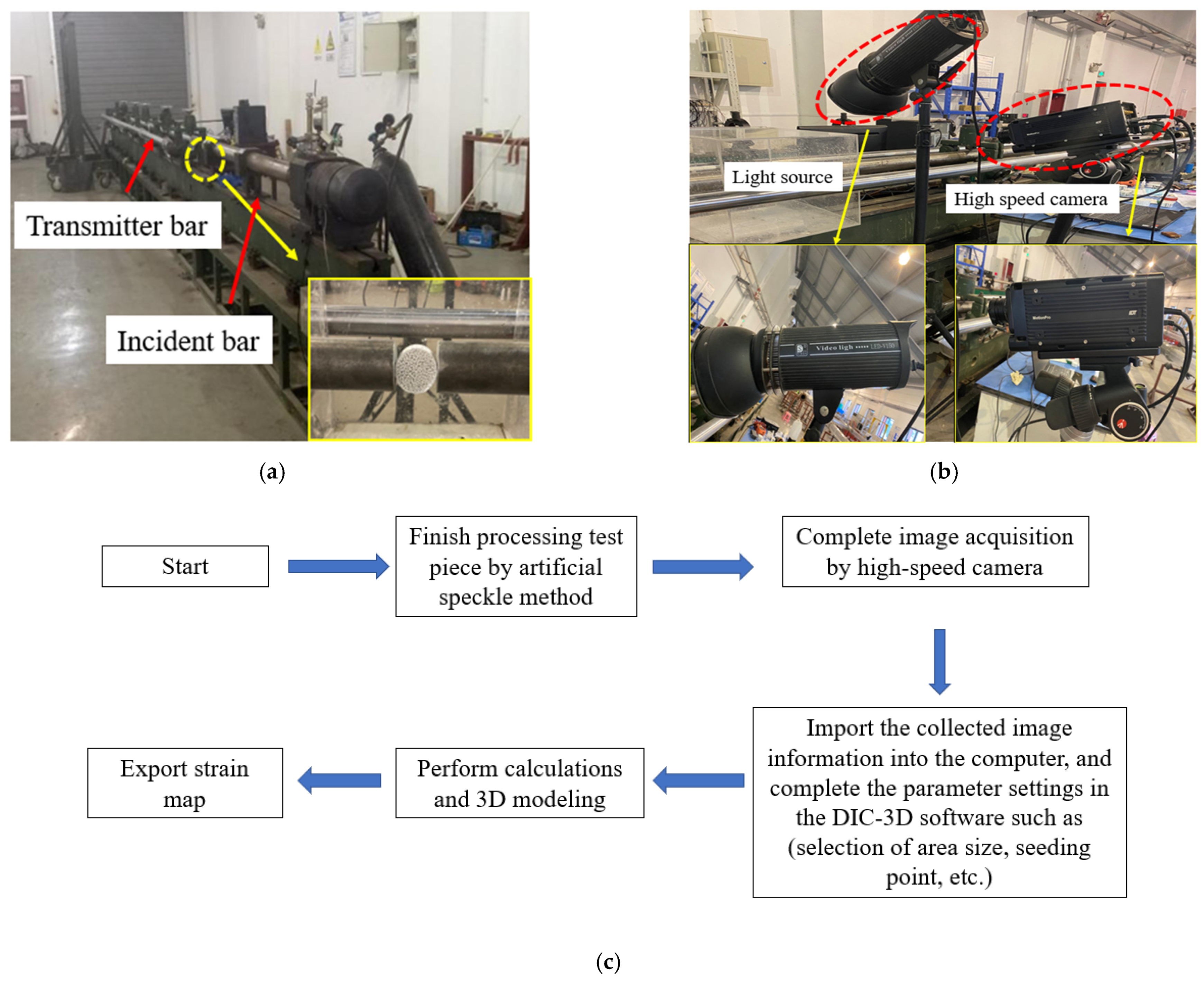
The dynamic test adopted the split Hopkinson pressure bar (SHPB) test device, as shown in Figure 3a, which was composed of an air gun, impact bar, incident bar, transmission bar, absorption bar, buffer, and data acquisition system. A bullet velocimeter was placed between the impact and incident bars, and strain gauges were attached to both the incident and transmission bars to record the stress changes during the test.
The diameters of the impact, incident, and transmission bars were all 75 mm, and the lengths were 0.4, 4.0, and 2.5 m, respectively. The material was steel, the steel density was 7800 kg/m3, and the elastic wave velocity was 5190 m/s.
The dynamic test process was combined with a high-speed camera, as shown in Figure 3b. The whole process of the dynamic splitting of the concrete specimens was photographed to collect DIC data and record the development process of specimen cracks.
The DIC method uses the basic principle of digital image processing to collect images with a high-speed camera, then records the surface topography features of specimens before and after deformation, and finally obtains a strain distribution nephogram with 3D modeling reconstruction and a DIC correlation algorithm. The operation process of the DIC method is shown in Figure 3c.

2.3. Test Design

2.3.1. Orthogonal Experimental Design

In order to improve the mechanical properties of the shaft lining concrete, the authors of this study focused on the C60 concrete, which is commonly used in shaft lining, and prepared hybrid fiber concrete by adding steel and polypropylene fibers (the two influencing factors of the test). The volume content of steel fiber was fixed to 2%; the volume contents of the polypropylene fiber were set to 0.05%, 0.1%, and 0.15%; and the length–diameter ratios of the polypropylene fiber were set to 3000, 6000, and 9000. A total of 11 groups of tests were conducted, and the orthogonal test design is illustrated in Table 6.

2.3.2. Specimen Preparation

In order to ensure that the steel and polypropylene fibers were evenly distributed in the concrete, the test blocks were made according to the following steps. (1) After weighing in accordance with the mix ratio, we put the cement, silica powder, fine river sand, and gravel into the mixer for 2 min; (2) then, we added 80% of the water-reducing agent into the water and evenly stirred before putting it into the blender for 2 min; (3) after that, we put the steel and polypropylene fibers into the mixer in batches and stirred for 2 min to ensure the uniformity of the mixing; (4) additionally, we put the remaining water-reducing agent into the mixer to achieve better fluidity; (5) after stirring, we put the whole mixture into the mold and vibrated it on the vibrating table; (6) finally, after 24 h, it was demolded and placed in a standard curing room for curing.
In the dynamic test (while considering the size of SHPB), the specimen size was chosen to be φ 65 × 35 mm, and nine cylinder specimens were used for each mix ratio. After the specimens were finished, the artificial speckle method was used to process the specimens. After smooth grinding, each specimen was first evenly sprayed on the surface of the cylinder with white matte paint and dried for 24 h. Then, black matte paint spots were evenly arranged on the white paint and dried for 24 h.

2.3.3. Test Principle

In the dynamic tests, we adjusted the air pressure of nitrogen in the gas gun to control the speed of the bullet, put the bullet velocimeter incident bar between the rod and impact bar, recorded the speed of the bullet fired every time, kept the specimen in between the incident bar and transmission rod, and adjusted the position of the high speed camera to shoot to entire shape of the specimen. However, our indoor light set-up could not meet the lighting requirements of the test, so a strong light source was placed beside the high-speed camera to ensure the clarity of the process pictures.
After the dynamic splitting test was completed, the data acquisition system was combined with the one-dimensional elastic stress wave theory of the SHPB test technology, the assumption of stress uniformity, Newton’s third law, and the Brazilian disc splitting principle. Then, the test data were processed according to Formula (1) and combined to obtain a stress–strain curve of the SHPB split tensile test piece.
A high-speed camera captured the whole process of the dynamic splitting failure of and recorded the crack propagation process of the hybrid fiber concrete specimen at a sampling frequency of 28,500 frames/s. According to the sampling frequency, the time difference between any two photos taken by a high-speed camera was about 35 ms.
ε ˙ = 2 C d ε R ( t ) ε ( t ) = 2 C d 0 t ε R ( t ) d t σ t = 2 A E π d l ε t ( t )
where σ t is the tensile stress of the splitting specimen (MPa), ε is the compressive strain, ε ˙ is the compression strain rate, E is the Modulus of elasticity of the pressure bar, A is the cross-sectional area (m2), C is the wave velocity m/s, d is the initial diameter of the test piece, l is the initial length, ε R is the reflected strain in the strut, and ε t is the transmission strain of the strut.

3. Results and Analysis

3.1. Static Test Results and Analysis

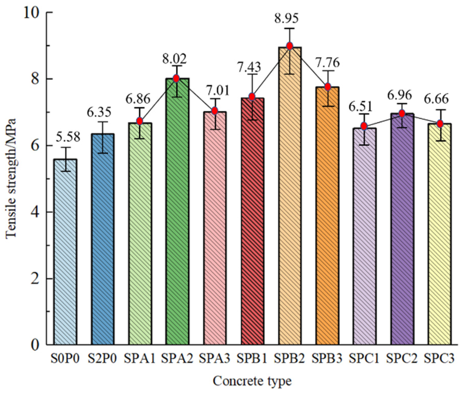
After standard curing, the specimens were removed and compressive and splitting tensile tests were carried out according to the GB/T50080-2016 Standard Test Method for Performance of Ordinary Concrete Mix and JGJ55-2011 Code for Design of Ordinary Concrete Mix. In the statics test, cubes with dimensions of 100 × 100 × 100 mm were selected, with six in each group for the compressive strength test and splitting tensile test, respectively. Additionally, the compressive and tensile strength calculation results had to be multiplied by conversion coefficients of 0.95 and 0.85, respectively. The orthogonal test results of each group of specimens are shown in Figure 4 and Figure 5. As can be seen from Figure 4, the compressive strength of the concrete in each fiber group was slightly increased by 14.6~25% compared to that of the base group. At the same volume content, the compressive strength of the concrete first increased and then decreased with the increasing length–diameter ratio of the polypropylene fiber. The compressive strength followed the same trend when the length–diameter ratio of the polypropylene fiber was constant. By comparing the test results of each group, it can be seen that the compressive strength of the SPB2 group was the highest, that is, when the volume content of steel fiber was 2%, the volume content of polypropylene was 0.1%, the length–diameter ratio was 6000, and the compressive strength of the hybrid fiber concrete was the highest.
As can be seen from Figure 5, the splitting tensile strength of concrete in each fiber group was significantly increased by 13.8~60.4% compared to that of the base group. At the same volume content of polypropylene fiber, the splitting tensile strength of concrete first increased and then decreased with the increasing length–diameter ratio. This was due to the fact that when the polypropylene length–diameter ratio was 3000 and 6000, its dispersibility in the concrete was sufficient enough for the concrete to have a large contact area, enhanced cohesion, enhanced friction, and (therefore) increased concrete splitting tensile strength. However, as the length–diameter ratio of the polypropylene fibers increased, the fibers could not be effectively dispersed and a weak surface was formed where the fibers gathered, thus reducing the split tensile strength of the concrete. When the length–diameter ratio of the polypropylene fiber was constant, the splitting tensile strength of the concrete first increased and then decreased with the increase in its volume content, which was due to the fact that when the volume of the polypropylene fiber was 0.05% and 0.1%, it was able to bridge cracks and enhance the bonding effects of the cement, thus effectively improving the splitting tensile strength of the concrete. However, as the volume of polypropylene increased, lumps easily formed during mixing, resulting in decreases in concrete compactness and increases in internal voids, thus reducing the splitting tensile strength of the concrete.
The combined analysis of the compressive and splitting tensile strength results showed that SPB2 is the optimal group, that is, the static properties of the concrete specimen mixed with 2% steel fiber and 0.1% polypropylene fiber at a length–diameter ratio of 6000 are the best.

3.2. SHPB Dynamic Results and Analysis

The SHPB test was carried out following the above-mentioned test method, and the test results are shown in Table 7 and Figure 6 and Figure 7.
Figure 6 and Figure 7 show the splitting tensile stress–strain curves of each group of specimens after the polypropylene fiber was mixed with steel fiber at different volume contents and draw ratios, respectively. The peak stress of the single addition steel fiber group increased by 15.7% compared to the reference group. Compared to the single addition steel fiber group, the peak stress of the 0.05%, 0.1%, and 0.15% SPA groups increased by 6.4%, 15.7%, and 4.0%; the peak stress in the 0.05%, 0.1%, and 0.15% SPB groups increased by 14.7%, 24.2%, and 12.6%; the peak stress in the 0.05%, 0.1%, and 0.15% SPC groups increased by 1.2%, 5.1%, and 2.9%, respectively. This shows that with the increase in polypropylene fiber volume content and the length–diameter ratio, the peak stress of each hybrid fiber group first increased and then decreased in comparison to the single addition steel fiber group. This was due to the fact that when the fiber volume and length–diameter ratio were moderate, the mixing of the two fibers had a positive effect on the peak stress of the concrete. When the fiber volume was too high or the length–diameter ratio was too large, the peak stress was negatively affected.
The change rule of the peak strain of the concrete specimens was similar to the peak stress rule. The peak strain of the single addition steel fiber group increased by 8.5% compared to the reference group. Compared to the single addition steel fiber group, the peak strain of the 0.05%, 0.1%, and 0.15% SPA groups increased by 49.7%, 52.8%, and 34.7%; the peak strain of the 0.05%, 0.1%, and 0.15% SPB groups increased by 61.13%, 65.28%, and 60.1%; and the peak strain of the 0.05%, 0.1%, and 0.15% SPC groups increased by 2.6%, 32.64%, and 18.7%, respectively. This shows that with the increase in polypropylene fiber volume content and length–diameter ratio, the peak stress of each hybrid fiber group has increased, but the lifting effect is obviously decreasing, indicating that the incorporation of hybrid fibers can significantly enhance the dynamic splitting deformation behavior.
The area enclosed by the stress–strain curve of concrete in Figure 6 and Figure 7 and Table 7 represents the dynamic toughness index under dynamic loading. The toughness index of the single addition steel fiber group increased by 8.5% compared to the reference group. Compared to the single addition steel fiber group, the 0.05%, 0.1%, and 0.15% SPA groups’ toughness index increased by 41.7%, 72.9%, and 33.3%; the 0.05%, 0.1%, and 0.15% SPB groups’ toughness index increased by 52.1%, 81.9%, and 46.5%; and the 0.05%, 0.1%, and 0.15% SPC groups’ toughness index increased by 27.8%, 38.3%, and 31.3%, respectively. These results show that the toughness index of the hybrid fiber concrete was significantly higher than that of the single addition steel fiber group, which indicates that the hybrid fiber was able to significantly enhance the dynamic toughness of the concrete. When the length–diameter ratio of the polypropylene fiber was constant, the dynamic toughness of concrete first increased and then decreased with the increase in the volume of the polypropylene fiber, and it reached its maximum value when the volume of polypropylene was 0.1%. This shows that the incorporation of hybrid fibers significantly improved the dynamic toughness of concrete since when micro-cracks began to appear inside the specimen, the incorporation of an appropriate amount of fibers effectively inhibited the development of macroscopic cracks, increased the residual stress of the concrete, and improved the toughness.
Since the time of impact loading was short, the DIC method was used here to observe the change in strain distribution before crack generation. Figure 8 shows strain nephograms for each specimen, illustrating two different change processes. The strain change of S0P0 (which is, the reference group) was relatively small and the strain rapidly concentrated at the initial moment of force, causing visible cracks. Moreover, each fiber hybrid group is initially subjected to an external force, and the internal strain of the concrete presents a discrete distribution, since the appropriate fiber incorporation was able to form a mesh structure within the concrete. Furthermore, as the loading force gradually increased, strain localization gradually appeared in the form of visible cracks. It was seen that the strain distribution of concrete was relatively stable before the development of cracks.
As can be seen from Table 8, the time required by S2P0 (i.e., the single addition steel fiber group) to arrive at T3 was significantly longer than that of S0P0 (i.e., reference group), increasing by 40.0%. The time required by SPB1, 2, and 3 (i.e., the mixed fiber group) to arrive at T3 was increased by 28.6%, 57.1%, and 14.3%, respectively, compared to that of S2P0 (i.e., the single addition steel fiber group), a trend that first rose and then dropped. The first visible crack takes longer, indicating that the dynamic toughness of the hybrid fiber group is improved.
When visible cracks appeared on the surface of the specimen, DIC data on the concrete surface could not be recorded. At this time, it was necessary to directly observe the pictures taken by high-speed photography to analyze the development process of the cracks. As shown in Figure 9, the crack failure of the specimen followed two different development processes. In the S0P0 reference group, a tiny crack first formed near the center, then gradually extended to both ends to form a straight line across the center of the specimen, and then gradually widened with the increase in loading time, the crack of the specimen was relatively flat and showed brittle fracture failure characteristics. Additionally, the fiber hybrid group first formed multiple tiny cracks near the center, and as the loading force gradually increased, a number of small cracks spread along the loading center to form a main crack. After the main crack is formed, due to the strong pulling effect of the fiber on the matrix material, the main crack expands along the width of the crack to form multiple cracks. As such, the specimen showed the characteristics of continuous and slow ductile failure.
As can be seen from Table 9, the time required by S2P0 (the single addition steel fiber group) to arrive at time T4 was significantly longer than that of S0P0 (the reference group), increasing by 50.0%. The time required for SPB1, 2, and 3 (the mixed fiber group) to arrive at T4 increased by 13.3%, 26.7%, and 7.7%, respectively, compared to S2P0 (the single addition steel fiber group), which showed a trend of first increasing and then decreasing. The longer time required to arrive at T4 indicated that the impact resistance of the mixed fiber group was improved.

4. Conclusions

In order to solve the high brittleness problem of vertical shaft lining under dynamic loading, the authors of this paper propose the addition of steel and polypropylene fibers to prepare high performance concrete. The static and dynamic mechanical properties and crack failure characteristics of steel–polypropylene-hybrid fiber-reinforced concrete were tested and studied, and the main conclusions were as follows:
(1)
According to the results of the static test, the compressive strength of the single addition steel fiber and hybrid fibers group slightly increased compared to that of the reference group, but the splitting tensile strength significantly increased. The splitting tensile strength of the optimal group increased by 40.9% compared to that of the single addition steel fiber group.
(2)
The SHPB test showed that the peak stress and strain of the optimal group (SPB2) were significantly higher than those of the other groups. The peak stress and strain of the optimal group (SPB2) were 24.2% and 65.28% higher than those of the single steel fiber group, respectively, and the toughness index was 81.9% higher. These results indicate that the hybrid fiber group had higher dynamic splitting tensile strength and dynamic toughness.
(3)
The DIC technique was used to analyze the strain distribution before visible cracks appeared in the specimens, and the results showed that compared to the reference group, greater strain dispersion appeared in the single addition steel fiber and hybrid fiber groups. Additionally, the time required for the first crack to appear in the optimal group (namely SPB2) was the longest, and the time to arrive at the first visible crack increased by 57.1% compared to the single steel fiber addition group.
(4)
The analysis of the crack failure form of the specimens showed that, compared to the reference group, the steel fiber and hybrid fiber groups showed the characteristics of continuous and slow ductile failure. Additionally, the main crack took the longest time to appear in the optimal group (SPB2), and the time before the main crack appearance was increased by 26.7% compared to that of the steel fiber group. These results indicate that the hybrid fiber was able to effectively improve the brittleness of concrete. Therefore, the steel–polypropylene-hybrid fiber-reinforced concrete studied in this paper can effectively resist impact loading and allow shaft lining to better cope with the effects caused by deep coal mining.

Author Contributions

Investigation, Q.Z. and W.Z.; methodology, Q.Z., Y.F. and X.H.; software, W.Z. and X.H.; data curation, Y.F. and Y.X.; formal analysis, Q.Z., Y.F. and X.H.; writing—original draft, Q.Z. and Y.F.; visualization, W.Z. and X.H.; writing—review and editing, Y.F., Y.X. and X.H.; conceptualization, Q.Z., Y.F. and X.H.; resources, W.Z.; supervision, X.H. and Y.F.; project administration, W.Z., Y.F. and Y.X.; funding acquisition, W.Z. and X.H. All authors have read and agreed to the published version of the manuscript.

Funding

This research was supported by the Anhui Provincial Natural Science Foundation (1808085ME160), Anhui University Natural Science Foundation (KJ2017A091), the China Scholarship Council (CSC), and Graduates’ Innovation Fund project of Anhui University of Science and Technology (2020CX2028).

Institutional Review Board Statement

Not applicable.

Informed Consent Statement

Not applicable.

Data Availability Statement

Not applicable.

Conflicts of Interest

The authors declare no conflict of interest.

References

  1. Yuan, L. Research progress of mining response and disaster prevention and control in deep coal mines. J. Chin. Coal Soc. 2021, 46, 716–725. [Google Scholar]
  2. Zhou, R.; Cheng, H.; Li, M.; Zhang, L.; Hong, R. Energy Evolution Analysis and Brittleness Evaluation of High Strength Concrete Considering the Whole Failure Process. Crystals 2020, 10, 1099. [Google Scholar] [CrossRef]
  3. Huang, X.W.; Zhou, A.; Wang, W.; Jiang, P. Characterization of the Dynamic Properties of Clay–Gravel Mixtures at Low Strain Level. Sustainability 2020, 12, 1616. [Google Scholar] [CrossRef] [Green Version]
  4. Wu, Q.; Ma, Q.; Huang, X.W. Mechanical Properties and Damage Evolution of Concrete Materials Considering Sulfate Attack. Materials 2021, 14, 2343. [Google Scholar] [CrossRef]
  5. Zheng, C.S.; Mehmet, S.K.; Chen, Z.W.; Saiied, M.A. Role of multi-seam interaction on gas drainage engineering design for mining safety and environmental benefits: Linking coal damage to permeability variation. Process Saf. Environ. 2018, 114, 310–322. [Google Scholar] [CrossRef]
  6. Liu, J.S.; Chen, Z.W.; Elsworth, D.; Qu, H.Y.; Chen, D. Interactions of multiple processes during CBM extraction: A critical review. Int. J. Coal Geol. 2011, 87, 175–189. [Google Scholar] [CrossRef]
  7. Wang, S.S.; Zhang, M.H.; Quek, S.T. Mechanical behavior of fiber-reinforced high strength concrete high strain-rate compressive loading. Constr. Build. Mater. 2012, 31, 1–11. [Google Scholar] [CrossRef]
  8. Yao, Z.S.; Fang, Y.; Zhang, P.; Huang, X.W. Experimental Study on Durability of Hybrid Fiber-Reinforced Concrete in Deep Alluvium Frozen Shaft Lining. Crystals 2021, 7, 725. [Google Scholar] [CrossRef]
  9. Yao, Z.S.; Fang, Y.; Kong, W.H.; Huang, X.W.; Wang, X.S. Experimental Study on Dynamic Mechanical Properties of Coal Gangue Concrete. Adv. Mater. Sci. Eng. 2020, 35, 426–442. [Google Scholar]
  10. Baek, B.; Lee, M.S.; Choi, C.S.; Chang, S.C.; Jung, H.S.; Choi, H.K. Evaluation of the Ultimate Strength of the Ultra-High-Performance Fiber-Reinforced Concrete Beams. Appl. Sci. 2021, 11, 2951. [Google Scholar]
  11. Norbert, V.; Akanshu, S. Behaviour of single bonded anchors in non-cracked and cracked steel fiber reinforced concrete under short-time tensile loading. Eng. Struct. 2021, 245, 112900. [Google Scholar]
  12. Qiu, M.H.; Zhang, Y.; Qu, S.Q.; Zhu, Y.P.; Shao, X.D. Effect of reinforcement ratio, fiber orientation, and fiber chemical treatment on the direct tension behavior of rebar-reinforced UHPC. Constr. Build. Mater. 2020, 256, 15–23. [Google Scholar] [CrossRef]
  13. Liu, Y.W.; Shi, C.J.; Zhang, Z.H.; Li, N.; Shi, D. Mechanical and fracture properties of ultra-high performance geopolymer concrete: Effects of steel fiber and silica fume. Cem. Concr. Compos. 2020, 112, 103665. [Google Scholar] [CrossRef]
  14. Su, J.; Shi, C.J.; Qing, H.J.; Zhang, X. Scale Effect of Flexural Strength on Ultra-high Performance Concrete. J. Chin. Ceram. Soc. 2020, 48, 1740–1746. [Google Scholar]
  15. Meng, K.; Xu, L.H.; Chi, Y. Experimental investigation on the mechanical behavior of hybrid steel-polypropylene fiber reinforced concrete under conventional triaxial cyclic compression. Constr. Build. Mater. 2021, 291, 123262. [Google Scholar] [CrossRef]
  16. Wang, X.; Cheng, H.; Wu, T.; Yao, Z.; Huang, X. Numerical Analysis of a Novel Shaft Lining Structure in Coal Mines Consisting of Hybrid-Fiber-Reinforced Concrete. Crystals 2020, 10, 928. [Google Scholar] [CrossRef]
  17. Zhang, H.; Wang, L.; Zheng, K.; Jibrin, B.T.; Totakhil, P.G. Research on compressive impact dynamic behavior and constitutive model of polypropylene fiber-reinforced concrete. Constr. Build. Mater. 2018, 187, 58495. [Google Scholar] [CrossRef]
  18. Afroughsabet, V.; Ozbakkaloglu, T. Mechanical and durability properties of high-strength concrete containing steel and polypropylene fibers. Constr. Build. Mater. 2015, 94, 73–82. [Google Scholar] [CrossRef]
  19. Li, Y.; Su, Y.Q.; Tan, K.H.; Zheng, X.T.; Sheng, J.L. Pore structure and splitting tensile strength of hybrid Basalte Polypropylene fiber-reinforced concrete subjected to carbonation. Constr. Build. Mater. 2021, 297, 123779. [Google Scholar] [CrossRef]
  20. Baboo, R.; Singh, N.K. Statistical and experimental study to evaluate the variability and reliability of impact strength of steel-polypropylene hybrid fiber-reinforced concrete. J. Build. Eng. 2021, 40, 102937. [Google Scholar]
  21. Deng, F.Q.; Xu, L.H.; Chi, Y.; Wu, F.H.; Chen, Q. Effect of steel-polypropylene hybrid fiber and coarse aggregate inclusion on the stress–strain behavior of ultra-high performance concrete under uniaxial compression. Compos. Struct. 2020, 252, 116285. [Google Scholar] [CrossRef]
  22. Chen, B.; Liu, J. Contibtion of hybrid fibers on the poperis of the hihstegt light weight concrete having good workability. Cem. Concr. Res. 2004, 35, 913–917. [Google Scholar] [CrossRef]
  23. Soon, P.Y.; Chun, H.B.; Alengaram, J.U.; Mo, K.H.; Jumaat, M.Z. Flexural toughness characteristics of steel-polypropylene hybrid fibre-reinforced oil palm shell concrete. Mater. Des. 2014, 57, 652–659. [Google Scholar]
  24. Wu, Y.; Li, J.; Keru, W. Mechanical properties of hybrid fiber-reinforced concrete at low fiber volume fraction. Cem. Concr. Res. 2003, 33, 27–30. [Google Scholar]
  25. Karthik, M.P.; Maruthachalam, D. Experimental study on shear behavior of hybrid fibre reinforced concrete beams. KSCE J. Civ. Eng. 2015, 19, 259–264. [Google Scholar] [CrossRef]
  26. Maurouxt, T.; Benboudjema, F.; Turcry, P.; Aït-MokhtaraO, A.; Deves, O. Study of cracking due to drying in coating mortars by digital image correlation. Cem. Concr. Res. 2012, 42, 1014–1023. [Google Scholar] [CrossRef]
  27. Sebaibi, N.; Benzerzour, M.; Abriak, N.-E. Influence of the distribution and orientation of fibres in a reinforced concrete with waste fibres and powders. Constr. Build. Mater. 2014, 65, 254–263. [Google Scholar] [CrossRef]
  28. Helfrick, M.N.; Niezrecki, C.; Avttabile, P.; Schmidt, T. 3D digital image correlation methods for full-field vibration measurement. Mech. Syst. Signal Process. 2011, 25, 917–927. [Google Scholar] [CrossRef]
  29. Liu, Q.; Xiao, J.Z.; Amardeep, S. Quantification of plastic shrinkage and cracking in mortars containing different recycled powders using digital image correlation technique. Constr. Build. Mater. 2021, 293, 123509. [Google Scholar] [CrossRef]
  30. Tedsco, J.W.; Ross, C.A. Experimental and numerical analysis of high strain rate splitting tensile tests. Mater. J. 1993, 90, 163–169. [Google Scholar]
  31. Bertelsen, I.; Kragh, C.; Cardinaud, G.; Ottosen, L.M.; Fischer, G. Quantification of plastic shrinkage cracking in mortars using digital image correlation. Cem. Concr. Res. 2019, 123, 105761. [Google Scholar] [CrossRef]
  32. Sebaibi, N.; Benzerzour, M.; Abriak, N.-E.; Binutry, C. Mechanical and physical properties of a cement matrix through the recycling of thermoset composites. Constr. Build. Mater. 2012, 34, 226–235. [Google Scholar] [CrossRef]
  33. Zhou, K.; Lei, D.; He, J.; Zhang, P.; Bai, P.; Zhu, F. Real-time localization of micro-damage in concrete beams using DIC technology and wavelet packet analysis. Cem. Concr. Compos. 2021, 123, 104198. [Google Scholar] [CrossRef]
  34. Nguyen, D.H.; Boutouil, M.; Sebaibi, N.; Baraud, F.; Leleyter, B. Durability of pervious concrete using crushed seashells. Constr. Build. Mater. 2017, 135, 137–150. [Google Scholar] [CrossRef]
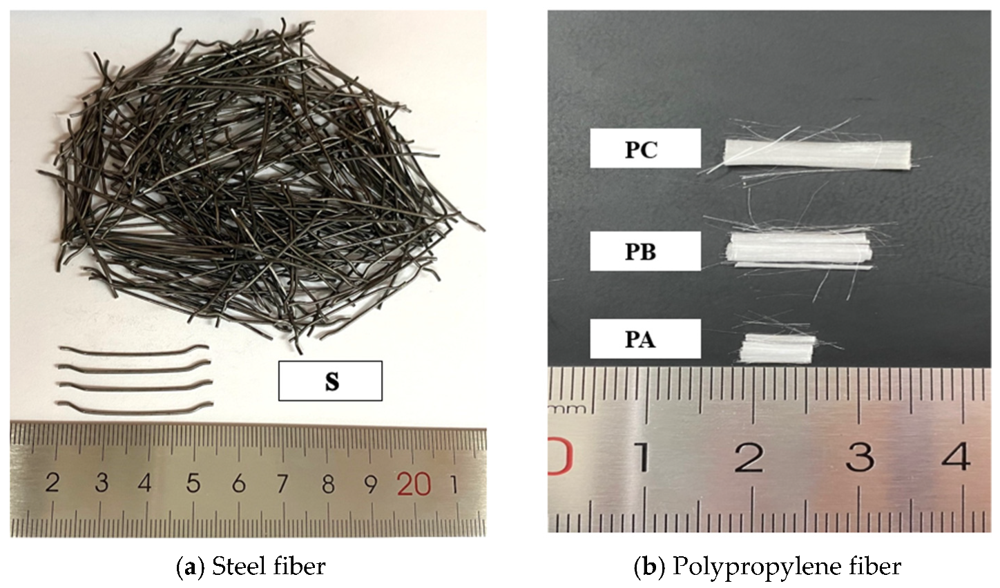
Figure 1. Fiber appearance characteristics.
Applsci 11 07926 g001
Figure 2. Static mechanical performance test: (a) Cube compression test; (b) cube split test.
Applsci 11 07926 g002
Figure 3. (a) SHPB device; (b) high-speed camera; (c) DIC method-related flow chart.
Applsci 11 07926 g003
Figure 4. Compressive strength of concrete specimens in each group.
Applsci 11 07926 g004
Figure 5. Splitting tensile strength of concrete specimens in each group.
Applsci 11 07926 g005
Figure 6. Splitting tensile stress–strain curves of specimens with different fiber lengths at 0.2 MPa of air pressure.
Applsci 11 07926 g006
Figure 7. Splitting tensile stress–strain curve of specimens with different fiber contents at 0.2 MPa of air pressure.
Applsci 11 07926 g007
Figure 8. Strain distribution nephograms of each specimen at different times: (a) Strain-nephogram corresponding to the initial stress time of the specimen (i.e., T1); (b) strain-nephogram corresponding to the moment before the crack appeared in the specimen (i.e., T2); (c) strain-nephogram corresponding to the moment when the crack appeared in the specimen (i.e., T3).
Applsci 11 07926 g008
Figure 9. Crack failure modes of each group of specimens at different moments: (a) The crack failure form corresponding to the time before cracks appeared in the specimen (i.e., T0); (b) the crack failure form corresponding to the time when cracks first appeared in the specimen (i.e., T3); (c) the crack failure form corresponding to the moment when the main crack first appeared in the specimen (i.e., T4).
Applsci 11 07926 g009aApplsci 11 07926 g009b
Table 1. Main performance parameters of cement.
Cement
Type
Setting Time (min)Compressive Strength (MPa)Flexural Strength (Mpa)
Initial
Setting
Final
Setting
3 d28 d3 d28 d
P·O 52.523528027.552.76.110.6
Table 2. Chemical composition and physical properties of silicon powder.
SiO2K2ONa2OIgnition Loss (%)Water Content (%)Specific Surface (m2/g)
96.30.850.123.670.7519.1
Table 3. Performance of water-reducing agent.
Water-Reducing
Rate/%
ColorDensity/
kg/m3
Bleeding Rate (%)Air Content (%)Shrinkage Ratio of 28 d (%)
≥25White1380≤95≤4.0≤135
Table 4. Basic ratio of concrete.
Cement (kg/m3)Silicon Powder (kg/m3)Fine Sand (kg/m3)Crushed Stone (kg/m3)Water (kg/m3)Water Reducer (kg/m3)
5406066096012012
Table 5. Performance index of each fiber.
Fiber Type Length/mmDiameter/mmDraw RatioTensile StrengthDensity (g/cm3)Modulus of Elasticity/GPa
Steel fiberS350.7546.7>11008210
PA60.00230001.24>3.5
Polypropylene fiberPB120.0026000>358
PC180.0029000
Annotations: S is steel fiber, PA is 6 mm polypropylene fiber, PB is 12 mm polypropylene fiber, and PC is 18 mm polypropylene fiber.
Table 6. Orthogonal test design.
Serial NumberSteel FiberPolypropylene
Volume Rate %Length–Diameter RatioVolume Rate %Length–Diameter Ratio
S0P0----
S2P02.046.7--
SPA12.046.70.053000
SPA22.046.70.103000
SPA32.046.70.153000
SPB12.046.70.056000
SPB22.046.70.106000
SPB32.046.70.156000
SPC12.046.70.059000
SPC22.046.70.109000
SPC32.046.70.159000
Annotations: S is steel fiber, PA is 6 mm polypropylene, PB is 12 mm polypropylene, PC is 18 mm polypropylene, 1 represents the volume content of 0.05% polypropylene, 2 represents the volume content of 0.1% polypropylene, and 3 represents the volume content of 0.15% polypropylene.
Table 7. SHPB dynamic split test results.
Name of
Specimens
Air Pressure (MPa)Average Peak
Stress (MPa)
Average Peak
Strain (10−3)
Toughness Index
S0P00.28.1891.780.0138
S2P00.210.4321.930.0142
SPA10.210.8572.690.0162
SPA20.212.0722.950.0219
SPA30.211.1082.890.0174
SPB10.211.6613.010.0181
SPB20.212.9523.190.0232
SPB30.211.7443.090.0189
SPC10.210.5611.980.0154
SPC20.210.9612.560.0169
SPC30.210.7362.290.0159
Table 8. The corresponding schedule of DIC strain nephograms for each group of specimens.
Name of Specimens T 1 / μ s T 2 / μ s T 3 / μ s
S0P070140175
S2P070210245
SPB170280315
SPB270350385
SPB370245280
Table 9. Corresponding schedule of crack failure form in each group.
Name of Specimens T 0 / μ s T 3 / μ s T 4 / μ s
S0P00175350
S2P00245525
SPB10315595
SPB20385665
SPB30280565
Publisher’s Note: MDPI stays neutral with regard to jurisdictional claims in published maps and institutional affiliations.