
Numerical Simulation on Reflective Cracking Behavior of Asphalt Pavement


Abstract
:1. Introduction
2. Methods
2.1. Method
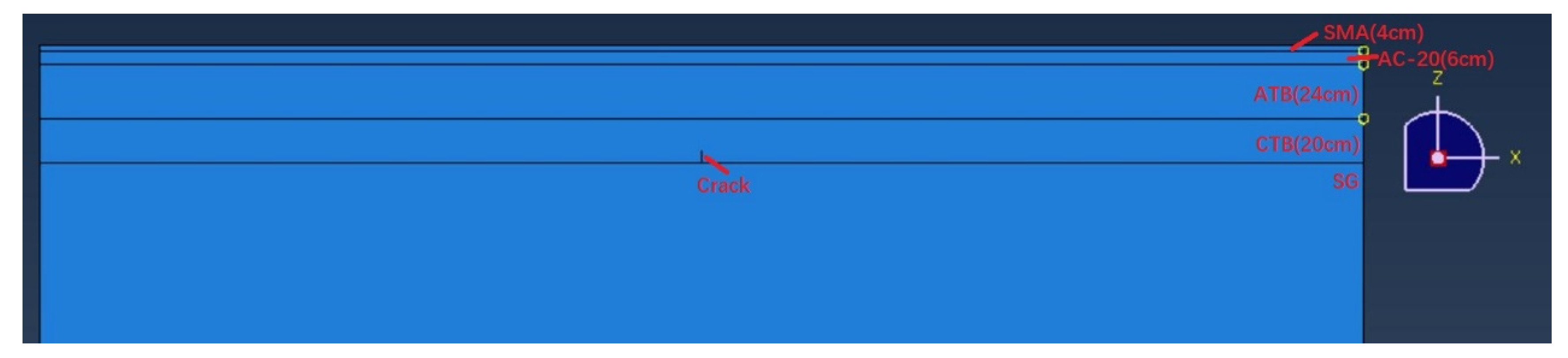
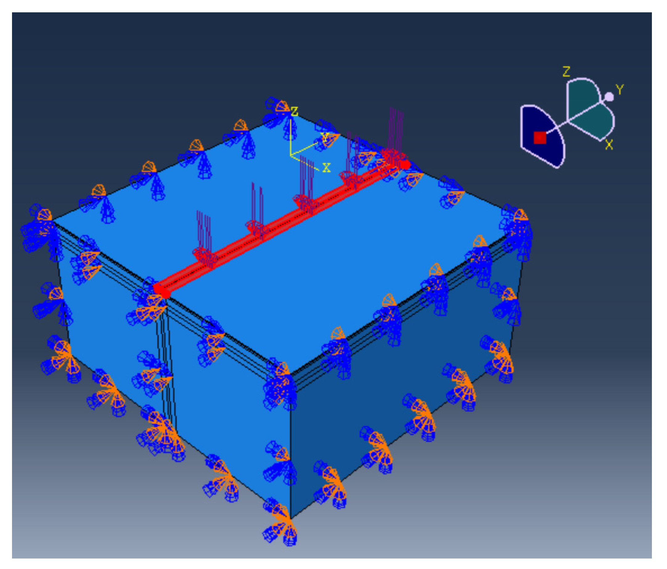
2.2. Simulation
3. Results and Discussion
3.1. Behavior of Crack Extension
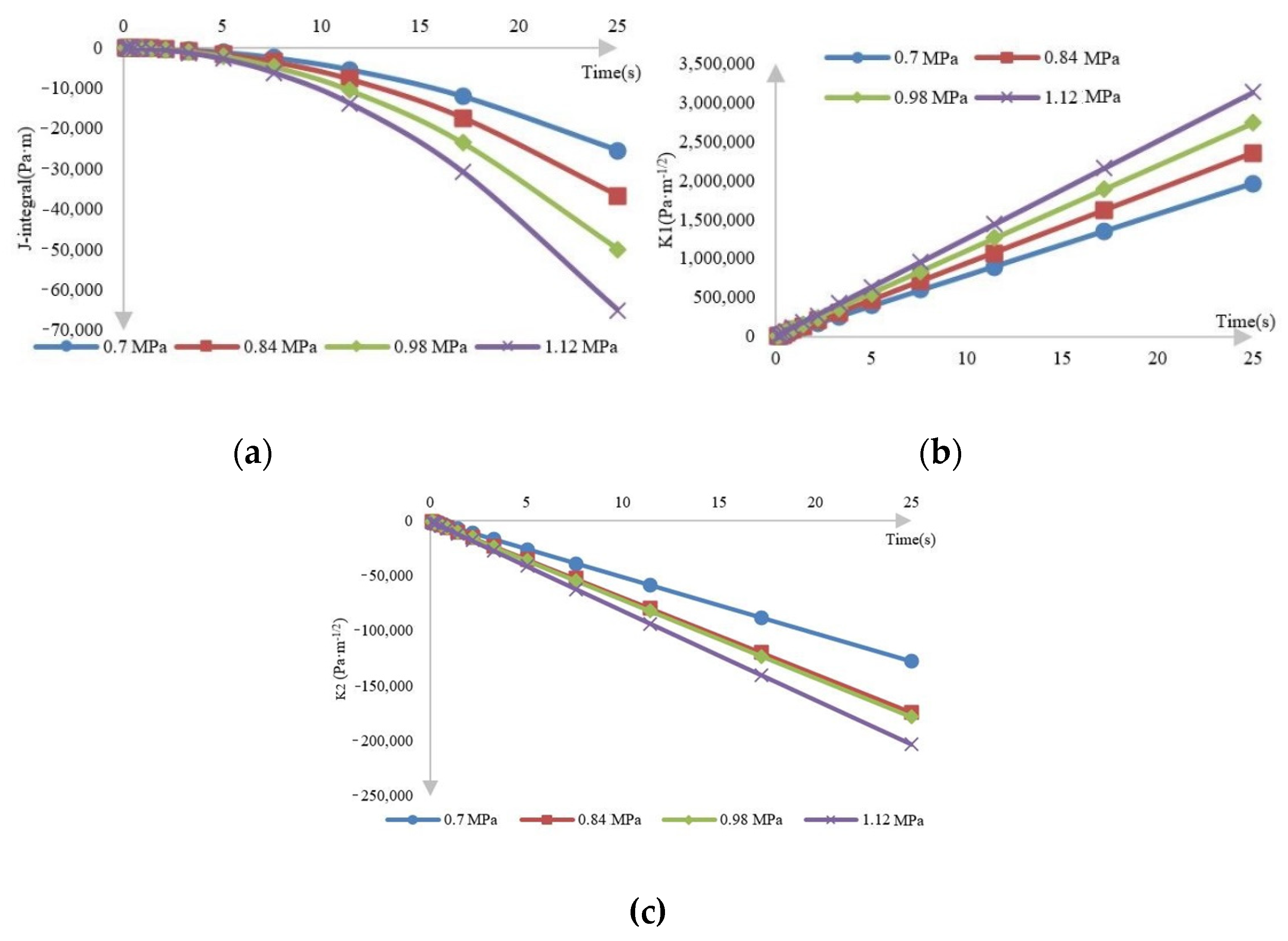
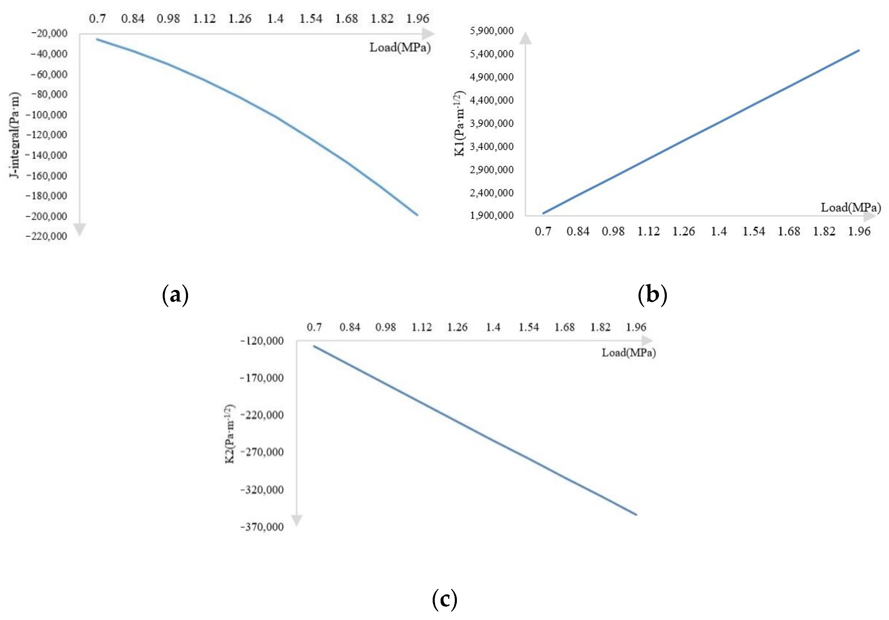
3.2. Traffic Loads
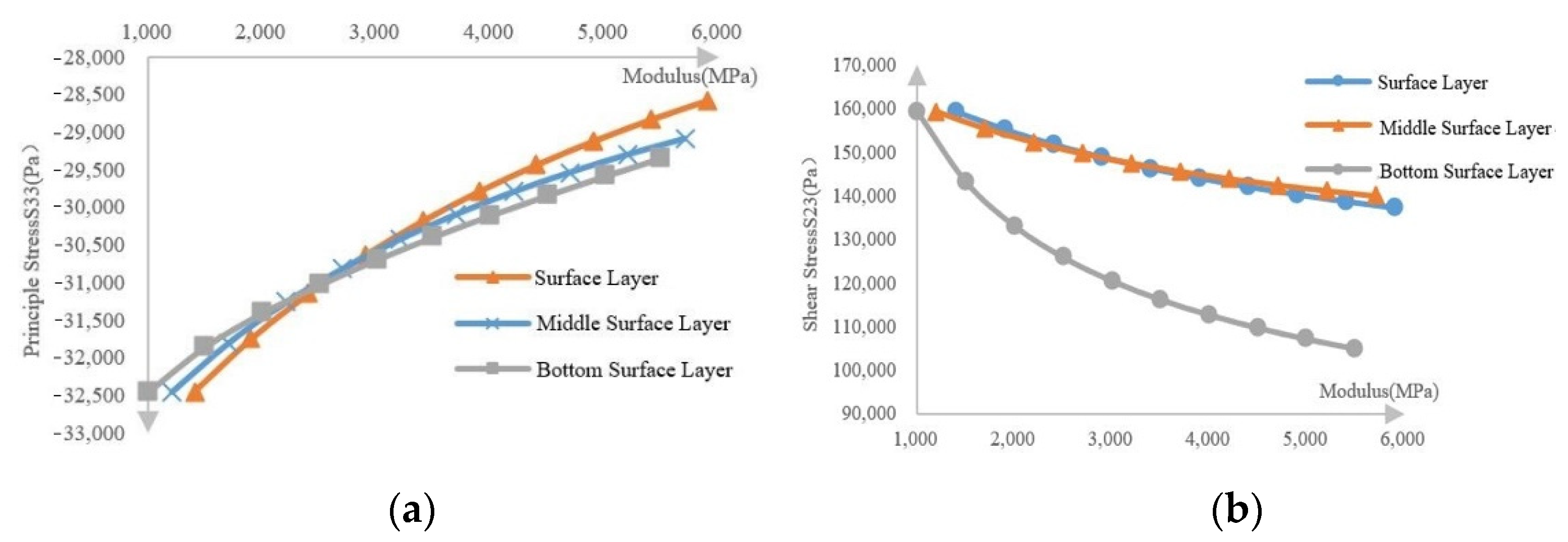
3.3. Layers with Different Young’s Modulus
3.4. Sensitivity of Various Influencing Factors on Asphalt Pavement
4. Conclusions
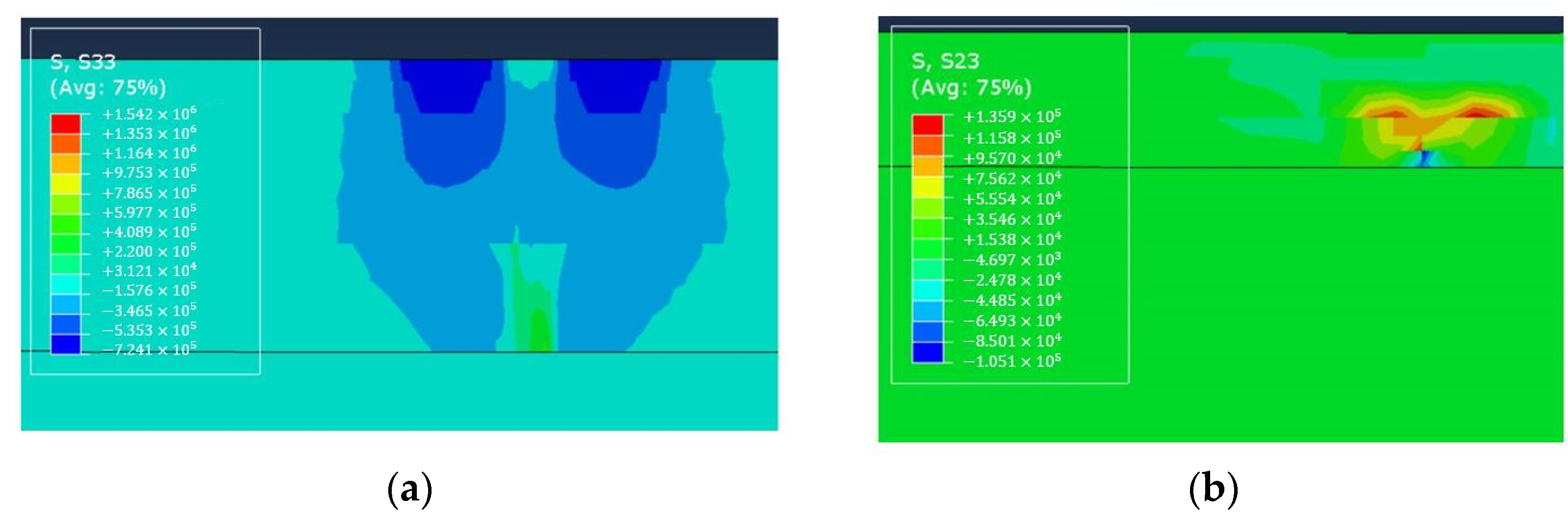
- A feasible three-dimensional pavement layered structure model was established, and numerical analysis was conducted using fracture mechanics theory and finite element software ABAQUS. The normal stress S33, shear stress S23, J-integral, and stress intensity factor K1 and K2 of the crack tip under different working conditions were calculated. Due to the existence of cracks, the difference between the positive and negative stresses between the base layer reached 2.209 × 10⁵ Pa, and the difference between shear stress reached 4.018 × 10⁴ Pa, indicating that the cracks showed a strong development trend both in the vertical and horizontal directions. The mechanical response of the crack tip is approximately a straight line when the vehicle load changes, and it is approximately an inverse proportional function when the modulus of each layer change. The R values of the fitted curves all reached over 0.99. In addition, the mechanical response of the stress and the stress intensity factor in some particular areas is high-order polynomial, generally second or third.
- Cracks will not strictly follow the preset path but will deviate from the preset vertical direction due to various factors. Therefore, in the actual monitoring of crack behavior, the normal stress and shear stress changes in the pavement structure should be monitored simultaneously in a larger area, and should not be limited to the crack tip.
- The load has a significant impact on the stress in the crack area. Under other conditions, the value of the stress change in the crack area is much smaller than under the load. In the process of increasing the load by 2.8 times, the principal stress increased by about 181.29%, and the shear stress increased by about 180.82%. In the process of increasing the modulus of each layer by 4500 MPa, the maximum reduction of normal stress is 11.93% of the surface layer, and the maximum shear stress is 34.13% of the ground layer. From a numerical point of view, the effect of increasing the modulus on crack propagation is relatively small compared with the effect of increasing load on cracking. Therefore, the vehicle load should be strictly limited to prevent road cracks.
- The entropy method was used to analyze the primary and secondary effects of various indicators in the process of reflecting crack propagation in asphalt pavement. The most important factor is the modulus of each layer, and the modulus of the bottom surface layer is the largest, followed by vehicle load. This shows that it is feasible to increase the modulus of each layer, especially the modulus of the bottom surface layer, to suppress the development of reflection cracks, but the impact of increasing the modulus on other road performance should not be ignored.
Author Contributions
Funding
Institutional Review Board Statement
Informed Consent Statement
Data Availability Statement
Conflicts of Interest
References
- Nemati, R.; Haslett, K.; Dave, E.V.; Sias, J.E. Development of a rate-dependent cumulative work and instantaneous power-based asphalt cracking performance index. Road Mater. Pavement Des. 2019, 20, S315–S331. [Google Scholar] [CrossRef]
- Isied, M.M.; Souliman, M. Integrated predictive artificial neural network fatigue endurance limit model for asphalt concrete pavements. Can. J. Civ. Eng. 2019, 46, 114–123. [Google Scholar] [CrossRef]
- Romeo, E.; Montepara, A. Characterization of Reinforced Asphalt Pavement Cracking Behavior using Flexural Analysis. Procedia-Soc. Behav. Sci. 2012, 53, 356–365. [Google Scholar] [CrossRef] [Green Version]
- Hu, S.; Basheer, I.; Leidy, J.; Zhou, F. Development of a Universal Cracking Amount Model for Fatigue and Reflective Cracking of Asphalt Pavements. J. Perform. Constr. Facil. 2017, 31, 04017109. [Google Scholar] [CrossRef]
- Ann Myers, L.; Roque, R.; Birgisson, B. Propagation Mechanisms for Surface-Initiated Longitudinal Wheelpath Cracks. Transp. Res. Rec. 2001, 1778, 113–122. [Google Scholar] [CrossRef]
- García, I.G.; Carter, B.J.; Ingraffea, A.R.; Mantič, V. A numerical study of transverse cracking in cross-ply laminates by 3D finite fracture mechanics. Compos. Part B 2016, 95, 475–487. [Google Scholar] [CrossRef]
- Okada, H.; Ishizaka, T.; Takahashi, A.; Arai, K.; Yusa, Y. 3D J-integral evaluation for solids undergoing large elastic–plastic deformations with residual stresses and spatially varying mechanical properties of a material. Eng. Fract. Mech. 2020, 236, 107212. [Google Scholar] [CrossRef]
- Yu, S.-M.; Cai, L.-X. Analytical J-integral model for mode-I cracks in ductile materials with three-dimensional constraints. Eng. Fract. Mech. 2021, 252, 107801. [Google Scholar] [CrossRef]
- Mehdinejad, S.; Fazaeli, H.; Moniri, A.; Dabiri, A.S. Comparison of two criteria of stress intensity factor and fracture energy to investigate the behavior of asphalt mixtures under combined tensile-shear loading modes-A statistical approach. Constr. Build. Mater. 2021, 290, 123230. [Google Scholar] [CrossRef]
- Alae, M.; Ling, M.; Haghshenas, H.F.; Zhao, Y. Three-dimensional finite element analysis of top-down crack propagation in asphalt pavements. Eng. Fract. Mech. 2021, 248, 107736. [Google Scholar] [CrossRef]
- Ma, X.; Quan, W.; Si, C.; Dong, Z.; Dong, Y. Analytical solution for the mechanical responses of transversely isotropic viscoelastic multi-layered asphalt pavement subjected to moving harmonic load. Soil Dyn. Earthq. Eng. 2021, 147, 106822. [Google Scholar] [CrossRef]
- Gdoutos, E.E. Fracture Mechanics: An Introduction; Gewerbestrasse, Springer Nature: Heidelberg, Germany, 2020. [Google Scholar]
- Rice, J.R. A path-independent integral and the approximate analysis of strain concentration by notches and cracks. J. Appl. Mech. 1968, 35, 379–386. [Google Scholar] [CrossRef] [Green Version]
- Melenk, J.M.; Babuska, I. The partition of unity finite element method: Basic theory and applications. Comput. Methods Appl. Mech. Eng. 1996, 139, 289–314. [Google Scholar] [CrossRef] [Green Version]
- Melenk, J.M.; Babuska, I. Approximation With harmonic and generalized harmonic polynomials in the partition of unity method. Comput. Assist. Mech. Eng. Sci. 1997, 4, 607–632. [Google Scholar]
- Deng, Y.; Luo, X.; Gu, F.; Zhang, Y.; Lytton, R.L. 3D simulation of deflection basin of pavements under high-speed moving loads. Constr. Build. Mater. 2019, 226, 868–878. [Google Scholar] [CrossRef]
- Sui, X.; Cao, L.; Ma, X.; Wang, H.; Dong, Z. Research on transversely isotropic permeability of asphalt pavement: Laboratory tests and computational simulation. Constr. Build. Mater. 2020, 251, 118958. [Google Scholar] [CrossRef]


| Layer | Thickness (cm) | Young’s Modulus @ 20 °C (MPa) | Poisson’s Ratio |
|---|---|---|---|
| SMA | 4 | 1400 | 0.35 |
| AC-20 | 6 | 1200 | 0.3 |
| ATB | 24 | 1000 | 0.3 |
| CTB | 20 | 1500 | 0.25 |
| SG | - | 40 | 0.4 |
| Mechanical Response | Surface Layer Modulus | Middle Surface Layer Modulus | Bottom Surface Layer Modulus | Traffic Load |
|---|---|---|---|---|
| J | 0.2444 | 0.2365 | 0.2558 | 0.2633 |
| K1 | 0.2443 | 0.2402 | 0.2872 | 0.2283 |
| K2 | 0.1846 | 0.1817 | 0.4262 | 0.2076 |
| S23 | 0.2335 | 0.2297 | 0.2791 | 0.2577 |
| S33 | 0.2528 | 0.2533 | 0.2568 | 0.2370 |
Publisher’s Note: MDPI stays neutral with regard to jurisdictional claims in published maps and institutional affiliations. |
© 2021 by the authors. Licensee MDPI, Basel, Switzerland. This article is an open access article distributed under the terms and conditions of the Creative Commons Attribution (CC BY) license (https://creativecommons.org/licenses/by/4.0/).
Share and Cite
Wang, H.; Wu, Y.; Yang, J.; Wang, H. Numerical Simulation on Reflective Cracking Behavior of Asphalt Pavement. Appl. Sci. 2021, 11, 7990. https://doi.org/10.3390/app11177990
Wang H, Wu Y, Yang J, Wang H. Numerical Simulation on Reflective Cracking Behavior of Asphalt Pavement. Applied Sciences. 2021; 11(17):7990. https://doi.org/10.3390/app11177990
Chicago/Turabian StyleWang, Houzhi, You Wu, Jun Yang, and Haopeng Wang. 2021. "Numerical Simulation on Reflective Cracking Behavior of Asphalt Pavement" Applied Sciences 11, no. 17: 7990. https://doi.org/10.3390/app11177990