Abstract
(1) Background: Metallic materials are predominantly used for spinal implants, and they can damage adjacent bones and intervertebral discs (IVDs) owing to their high elastic moduli. Consequently, there is a possibility that serious complications, such as kyphosis, may occur as the sequelae progresses. In this study, the behavior of the lumbar spine and implant system was evaluated using the finite element (FE) method, by applying the porous structure to the spinal implants to resolve the problem of metal spinal implants. (2) Methods: An FE model was developed for lumbar 3–5, and it was assumed that, owing to disease occurrence, spinal implants were placed in lumbar 3–4. Currently, Ti–6Al–4V is the most commonly used material for spinal implants. The shape of the porous structure was set in the form of a diamond, and porosity was varied over nine values ranging from 0 to 81%. Finally, equivalent material properties of the porous structure were derived using the Ramberg–Osgood formula, with reference to experimental study. (3) Results: The range of motion was increased, and the equivalent stress of adjacent IVD, and adjacent bone stress of the pedicle screw and spinal cage, decreased with increasing porosity of the spinal implants. As the porosity decreased, the safety factor exhibited a tendency to decrease rapidly. (4) Conclusion: Motor capacity of the spine was improved, and the equivalent stress of the spinal tissues decreased with the increasing porosity of the spinal implants. Therefore, in the future, porous structures can significantly contribute to the improvement of implants through continuous complementary research.
1. Introduction
Spinal implants––pedicle screws, spinal cages, and spinal rods––are medical devices used in the surgical treatment of patients with spinal diseases. They play a crucial role in supporting the spine through effective selection and combination. Currently, titanium alloys, such as Ti–6Al–4V, are used for spinal implants because of their lower range of motion (ROM) and higher modulus of elasticity compared to living tissue. However, the spinal implants curb the movement of the spine and damage adjacent living tissues, such as adjacent bones and intervertebral discs (IVDs), leading to problems such as increased pain, loss of function, and risk of revision surgery. Recently, a flexible material-based spinal device was proposed to achieve a more uniform load distribution and to reduce side effects. Materials such as polyetheretherketone (PEEK), which is a relatively more flexible material that can reduce stress shielding and perform uniform load distribution, have been proposed as alternatives to metals. Recent studies have shown that PEEK spinal implants are similar to titanium alloy spinal implants in terms of biocompatibility, but they have a lighter weight and lower elastic modulus compared to the metal implants, which can reduce heterogeneity and minimize damage to adjacent living tissues. However, there are problems in the fusion of the spinal cage and difficulty in further deformation into a shape suitable for the patient during surgery [1,2,3,4,5,6,7,8,9,10,11].
Carbon fiber-reinforced PEEK (CFR-PEEK) has been used in several studies to reduce the elastic modulus of spinal implants, and the stress on adjacent bone, and thus solve the problem of metal implants affecting the medical imaging of tumor patients [12,13,14,15,16,17]. Li et al., Cao et al., and others have implemented a porous structural implant using 3D printing technology to improve spinal motion, minimize damage to adjacent vertebral tissues, and improve bone fusion [18,19,20,21,22,23,24,25]. Spinal implants were applied to the vertebral body, and their behavior under spinal motion was investigated using the finite element method (FEM) [26,27,28,29,30,31]. However, these studies were limited to retrospective clinical studies, or new materials, such as porous metal structure implants and CFR-PEEK, were applied only to a portion of the spinal implant. Therefore, investigation of the application of porous structure to metal spinal implants, such as pedicle screws, spinal cages, and spinal rods, and study of the behavior of the vertebral body using FEM has been insufficient in conventional studies.
In this study, the safety and applicability of porous spinal implants of various porosities, developed using 3D printing, were evaluated using FEM to resolve the problems of metal spinal implants. Nine values of porosity, ranging from 0% to 81%, were applied to a porous pedicle screw, spinal cage, and spinal rod to evaluate the ROM of each spinal motion, the equivalent stress on the adjacent bone and IVD, and the safety factor of the implant.
2. Materials and Methods
2.1. Characteristics of Spinal Implant
The purpose of surgical treatment of spinal disease is to stabilize the spine and correct spinal deformities using a spinal fixation system. It consists of a pedicle screw, a spinal cage, and a spinal rod. Since the first usage of stainless steel as a material for spinal implants, various biocompatible materials such as titanium (Ti), titanium alloy, cobalt chrome (CoCr) alloy, and PEEK have been studied and commercialized. Currently, Ti–6Al–4V, a titanium alloy, is mainly used owing to its excellent mechanical properties, biocompatibility, and corrosion resistance. It is manufactured in accordance with the characteristics of the human body, such as the precise curvature of the spine, bone density, and the severity of the disease [1,2,3,4,5].
After spinal implants are placed in the diseased part of the spine, many problems such as pull-out of the pedicle screw, breakage, and damage to adjacent spinal tissues due to stress shielding have been reported. It can also cause permanent disability and impossibility of reoperation. Therefore, there is a need to improve human body-friendly spinal implants [6,7].
2.2. Finite Element Modeling and Validation
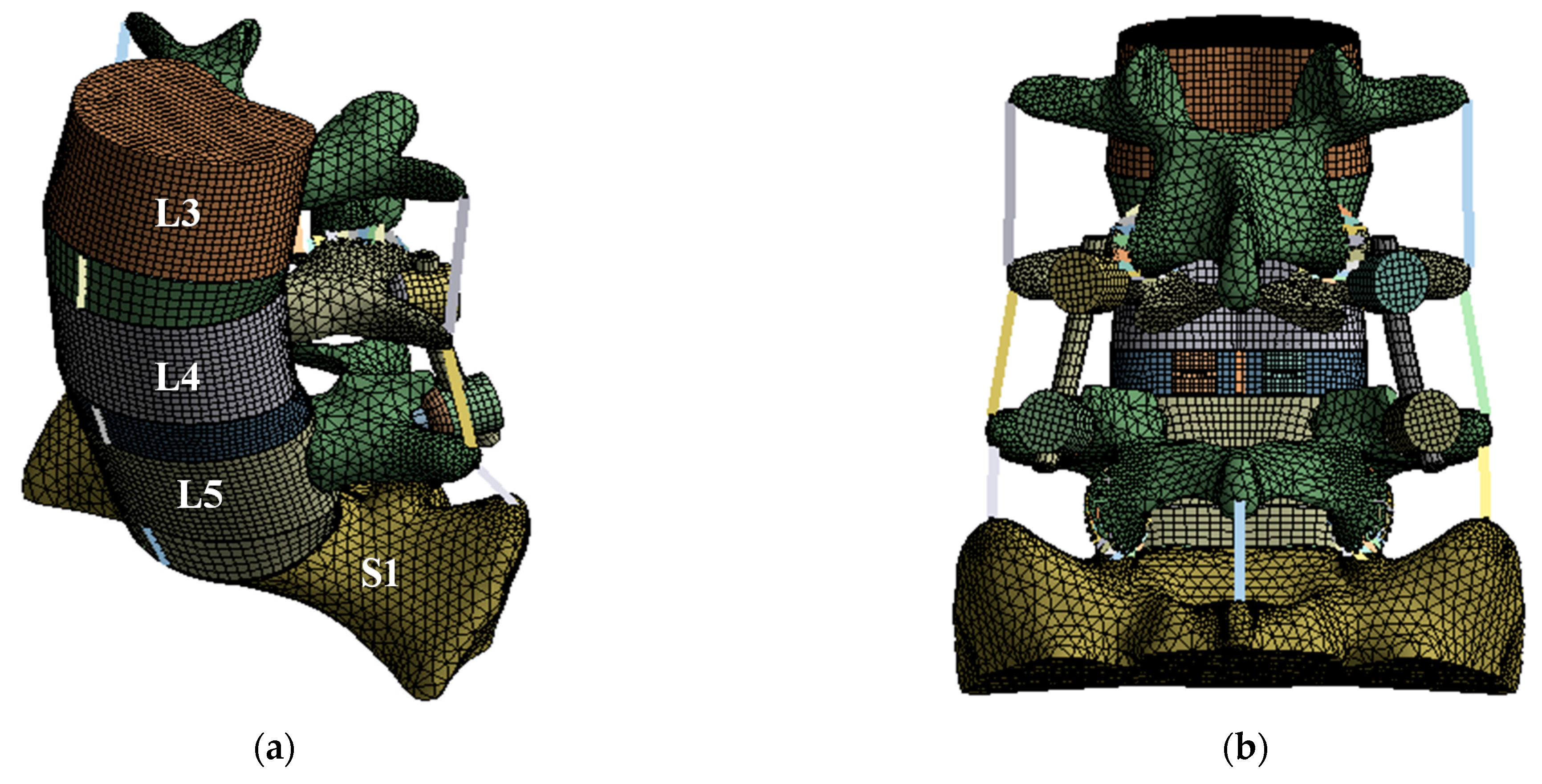
A finite element (FE) model of the lumbar spine, which has the highest incidence of spinal disease, was developed and used in this study. The FE model used a three-dimensional eight-node hexahedral element for the anterior vertebral body and intervertebral disc, and a three-dimensional five-node tetrahedral element for the posterior vertebral body. A one-dimensional beam element (tension only) was applied to each ligament. Table 1 lists the material properties of the cortical and trabecular bone, ligaments, intervertebral disc, and the spinal implants of the lumbar spine, which were applied to the FE model [27,32,33,34,35,36,37]. The lordosis of the FE model was set to 45°, which is the same as that of a normal lumbar spine. Furthermore, a part of the sacrum was modeled for evaluation of the intervertebral disc between lumbar 5 to sacrum 1. For each implant of the spinal fixation system, the pedicle screw diameter was 3.0 mm, the spinal cage dimensions were 10.0 × 29.0 × 10.0 mm3, the spinal rod diameter was 5.5 mm, and the bone graft was applied to the area where the intervertebral disc was removed. Figure 1 shows the detailed FE model [37].

Table 1.
Material properties of lumbar spine and spinal implants.

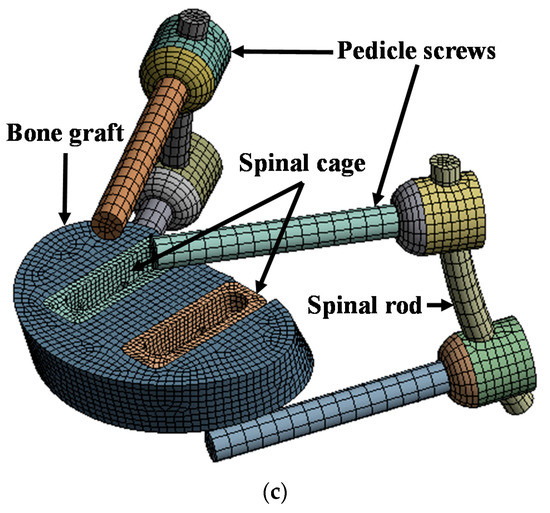
Figure 1.
Finite element (FE) model of lumbar spine and spinal implants: (a) isometric view of FE model of lumbar spine and spinal implants; (b) rear view of FE model of lumbar spine and spinal implants; (c) isometric view of spinal implants.
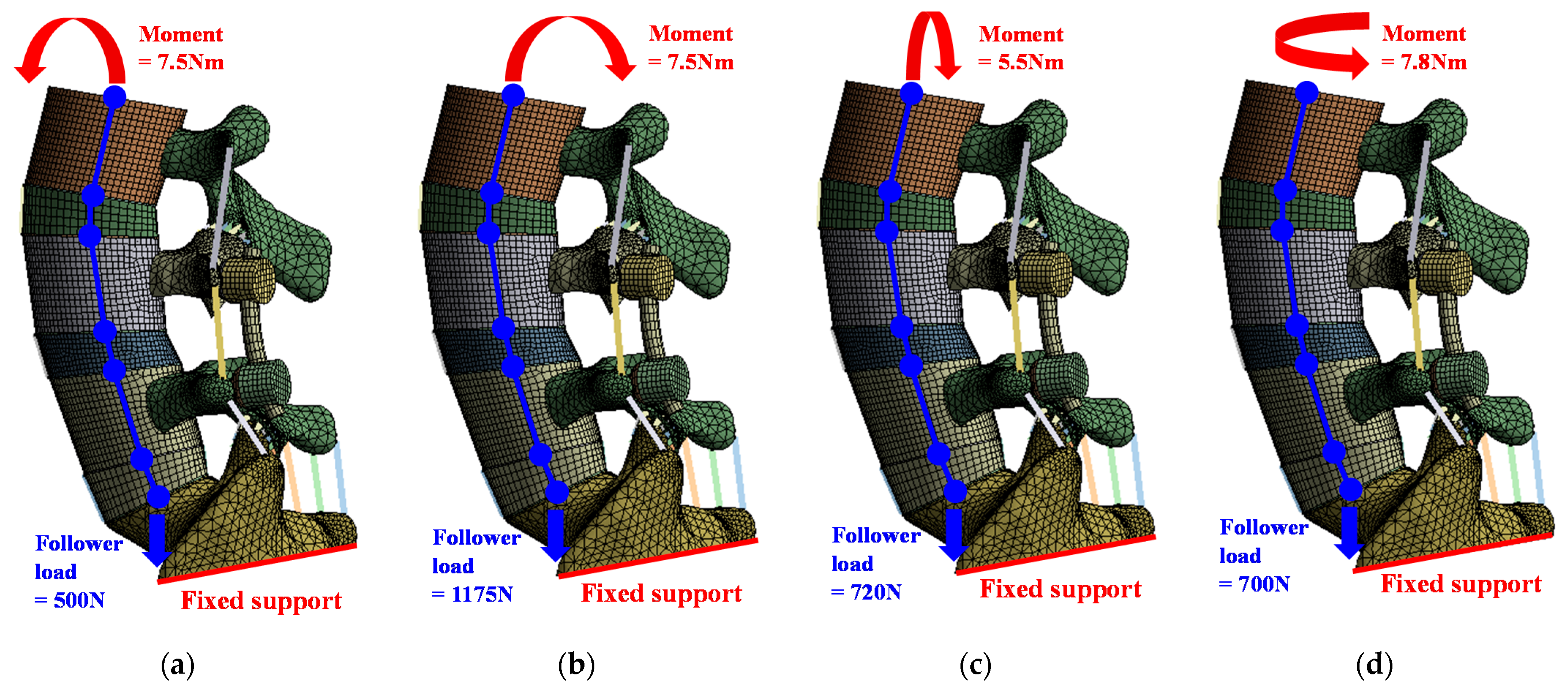
The loading conditions were applied according to spinal motions, that is, flexion, extension, lateral bending, and rotation, and different follower loads and moments were set for each motion. Follower load was applied similarly to the cadaver experimental study of Renner et al. Follower load is a compressive load that occurs along the axis of the lumbar. In the FE analysis, the middle node of the top and bottom end plates of each segment is coupled with the surface of the endplate, and the nodes are connected through a connector. By applying the load in the direction of gravity from the top of the sacrum, the follower load was applied along the axis of the lumbar.
The boundary condition was applied as a fixed support for the bottom of the sacrum. In the contact conditions, most of the lumbar FE model, such as cortical-trabecular bone, cortical bone-IVD, and anterior bone-posterior bone, were adjusted bonded conditions; soft contact and a frictional coefficient of 0.1 were used only for the facet joint. Figure 2 shows the detailed loading and boundary conditions [32,33].
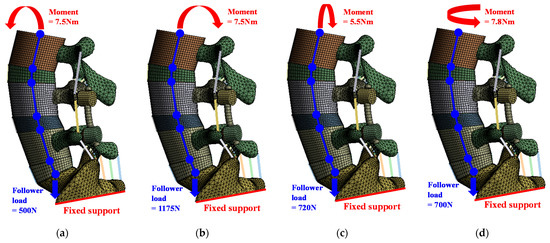
Figure 2.
Loading and boundary conditions for simulation of six spinal motions: (a) flexion; (b) extension; (c) lateral bending; (d) rotation.
To verify the reliability of the current FE model, it was compared to the results of cadaver experiments and FE analysis in the papers of Renner et al. and Huang et al. The FE model of this study is difficult to compare to the lumbar of the human body. There are many restrictions on conducting experiments with cadavers. Therefore, the FE model was verified through comparison of the lumbar cadaver experiment results of conventional studies. The results of the cadaver experiment and FE analysis of conventional studies were compared for the FE model validation of the current study. In the verification of the intact FE model, the material properties shown in Table 1 were used, and a pure moment was applied to each lumbar motion (flexion 8Nm, extension 6Nm, lateral bending 6 Nm, and rotation 4 Nm). Boundary condition was set as a fixed support at the bottom of the sacrum, as shown in Figure 2 below. The FE model of the current study was satisfied within standard deviation in all motions in comparison to the cadaver experiment results of Renner et al., and the maximum error was −2.18 degree in lumbar 5–Sacrum 1 under flexion-extension. A maximum error of 3.80 degree was investigated in lumbar 4–5 under lateral bending with FE analysis results of Renner et al., and the maximum error was −2.21 degree in lumbar 5–Sacrum 1 under extension-flexion with Huang et al. Figure 3 shows the detailed validation of the FE model. Although the current FE model differs from the compared FE model in the number of segments, etc., it may cause some problems in the reliability of verification. However, it is considered that the reliability of the current FE model has been verified through the following reasons. First, the current FE model was satisfied within the standard deviation of the cadaver experiment study of Renner et al. Second, the error between the cadaver experiment and the FE analysis results of Rennet et al. is large. Finally, it shows similar results of ROM in the FE analysis between Huang et al. and the current study. We will develop a more reliable FE model though additional and more diverse considerations in further studies [37,38].
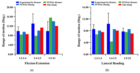
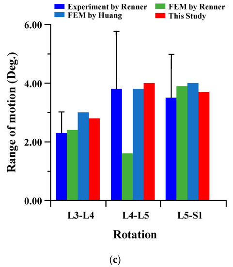
Figure 3.
Comparison of range of motion (ROM) of intact FE model between the current study and conventional studies of Renner et al. and Huang et al.: (a) flexion-extension; (b) lateral bending; (c) rotation.
2.3. Scenarios of Spinal Rod for Finite Element Analysis
The spinal FE model was developed from lumbar 3 to sacrum 1, and the surgical part of the lumbar spine was set from lumbar 3–4. The porosity values of the spinal implants were selected to be 0%, 34%, 50%, 73%, and 81%, based on the results of the diamond porous structure tensile test by Falkowska et al. Additionally, the FE analysis for porosity values of 75%, 60%, 40%, and 15% was performed by estimating the mechanical properties according to the Ramberg–Osgood formula. The true stress–true strain curve was used to improve the simulation precision of the vertebral body and spinal implant behavior. ANSYS workbench 2019 R1 (ANSYS Inc., Pittsburgh, PA, USA) was used for the FE analysis [36,39,40].
The material properties at different porosities, which were not presented in the study by Falkowska et al., were estimated according to the following Ramberg–Osgood formula:
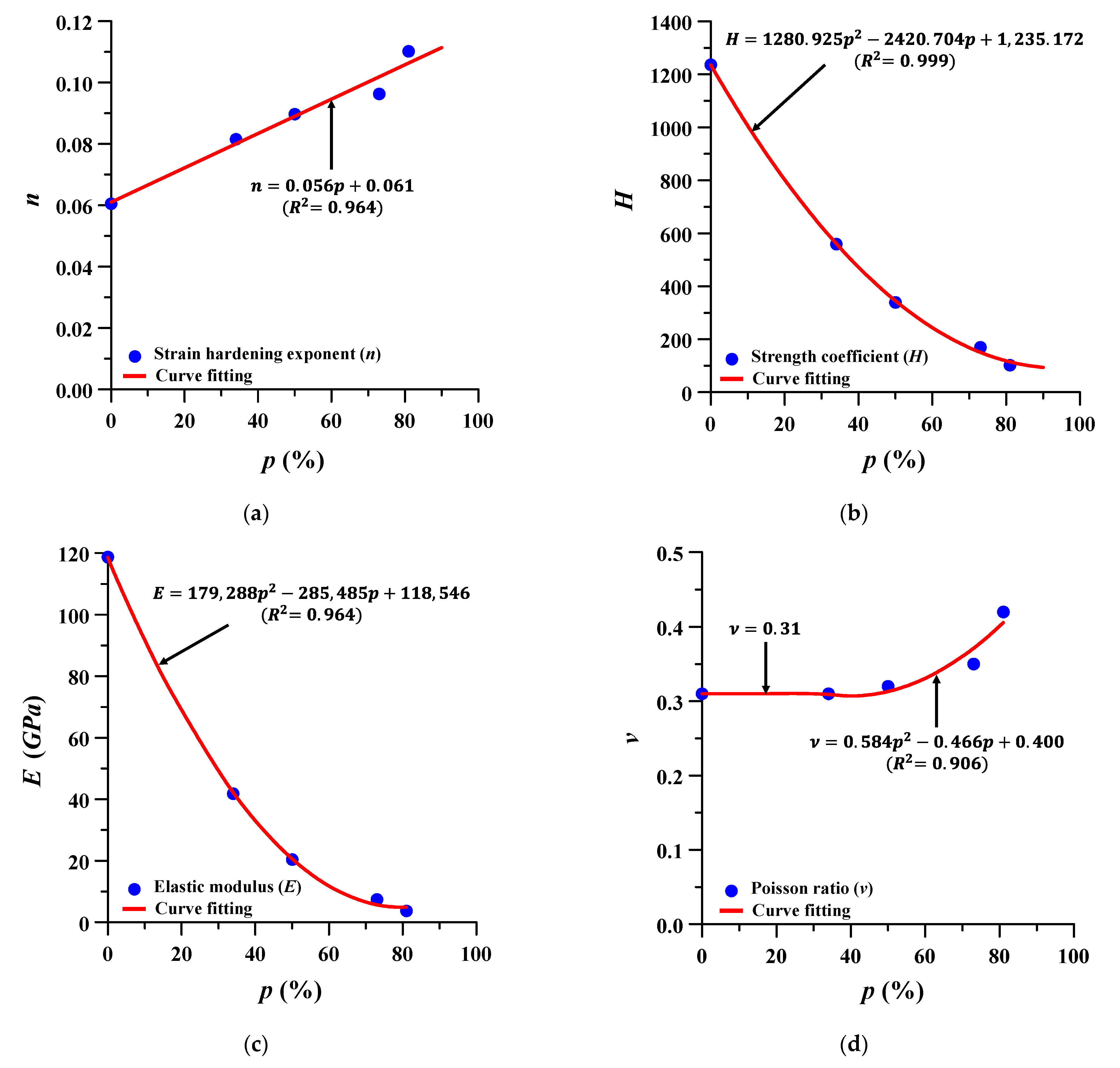
To estimate the material properties, the true stress–true strain behavior of the Ti–6Al–4V porous structure was obtained from the tensile test results presented by Falkowska et al., and, subsequently, the variables of the Ramberg–Osgood formula (strain hardening exponent (n) and strength coefficient (H)) were obtained [36,39]. Table 2 lists the details of the variables of the Ramberg–Osgood formula from the tensile test result presented by Flkowska et al.
Table 2.
Strain hardening exponent (n), strength coefficient (H), elastic modulus (E), and Poisson’s ratio (ν) of Ti–6Al–4V at different porosities (p).
The formulae for estimating the material properties of Ti–6Al–4V at different porosities were to be expressed by the following Equations (2)–(5), and the corresponding porosity, that is, 75%, 60%, 40%, and 15%, was estimated using these same formulae. Figure 4 and Figure 5 show the variable estimation of Ramberg–Osgood formula and the estimated stress–strain curves, respectively. A total of nine scenarios were selected for FE analysis from 0% to 81%, and the porosity and material properties of each scenario are summarized in Table 3.
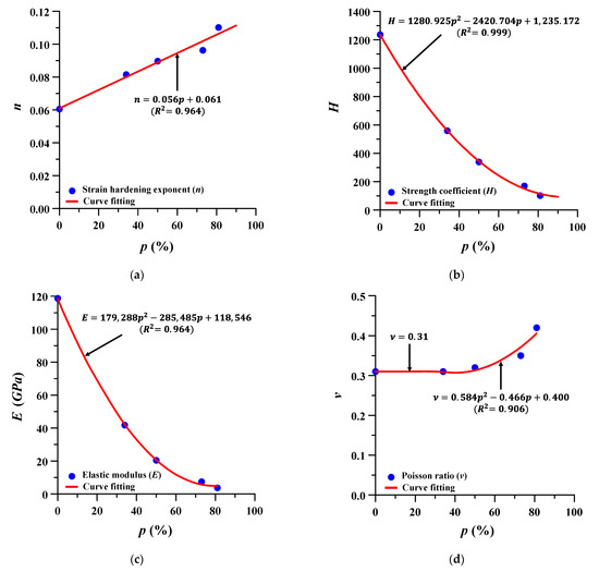
Figure 4.
Estimation formula of material properties of Ti–6Al–4V at different porosities (p): (a) strain hardening exponent (n); (b) strength coefficient (H); (c) elastic modulus (E); and (d) Poisson’s ratio (ν).
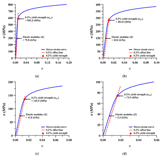
Figure 5.
Stress (σ)–strain (ε) behavior of Ti–6Al–4V at different porosities: (a) porosity 15%; (b) porosity 40%; (c) porosity 60%; (d) porosity 75%.
Table 3.
Scenarios for spinal motion simulation using spinal implants at different porosities (p): elastic modulus (E), Poisson ratio (v), and 0.2% yield strength (σ0.2) at each scenario.
3. Results
The analysis results of the porous spinal implants were recorded. ROM of the lumbar spine, equivalent stress of the spinal implant adjacent to the bone and intervertebral disc, and the safety factor of the spinal implants were evaluated.
3.1. Range of Motion
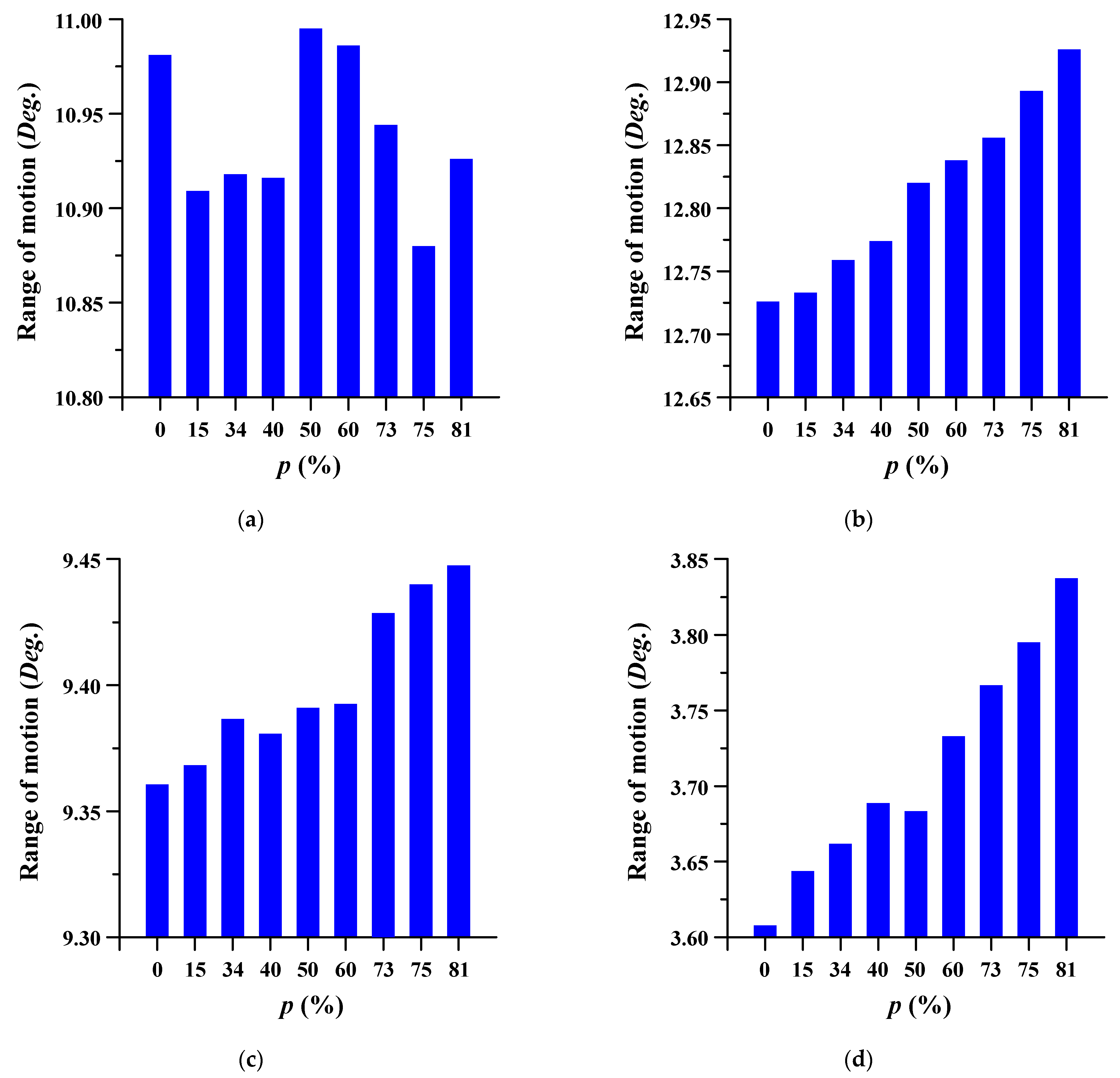
The ROM of the lumbar spine in which the spinal implant was placed was evaluated at different porosities. ROM is the measurement of the rotation angle before and after FE analysis of the center of the top of each segment (lumbar 3–5) based on the top of the sacrum. The measurement points of each segment were set through the remote point, and the angle was measured using a flexible rotation probe, a function provided by ANSYS workbench [41]. The trend of the ROM increased as the porosity increased. Figure 6 and Figure 7 show the ROM and deformation behavior of the lumbar spine, respectively.
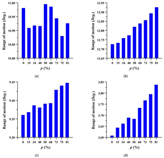
Figure 6.
The range of motion (ROM) of the lumbar spine at different porosities (p) of the spinal implants in each spinal motion: (a) flexion; (b) extension; (c) lateral bending; and (d) rotation.
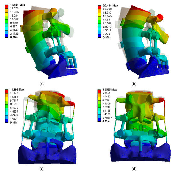
Figure 7.
The deformation distribution of the lumbar spine at spinal implant porosity of 81% in each spinal motion: (a) flexion; (b) extension; (c) lateral bending; and (d) rotation (unit: mm).
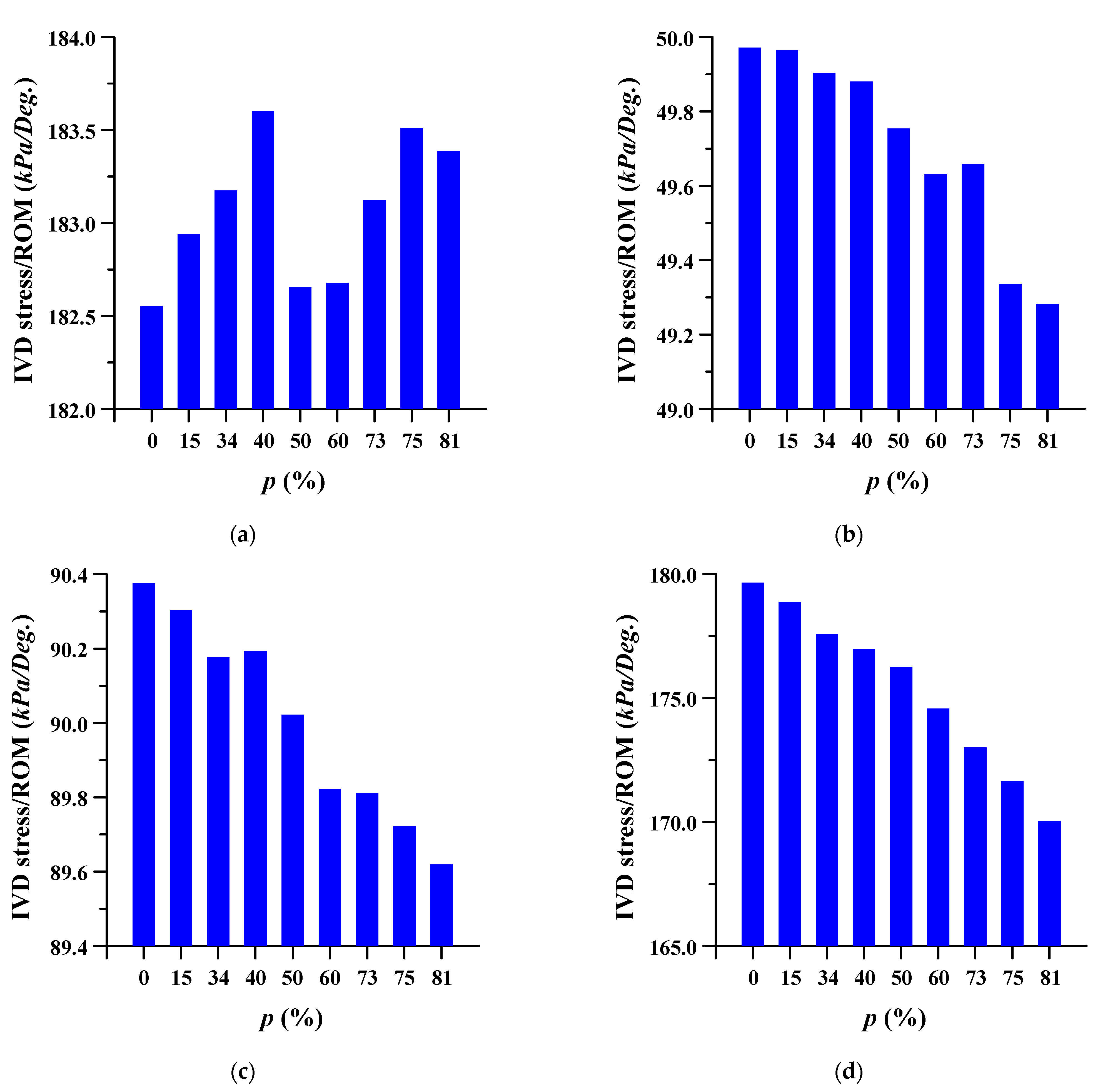
3.2. Equivalent Stress at Adjacent Intervertebral Disc
The equivalent stress per ROM in the adjacent intervertebral disc where the spinal implant was placed at different porosities was studied. The equivalent stress per ROM of the adjacent intervertebral disc decreased as the porosity of the spinal implants increased. However, the equivalent stress per ROM showed almost the same pattern (except for a porosity of 81%) in the case of flexion, at the intervertebral disc between lumbar 3 and 4. As the porosity of the spinal implants increased, the equivalent stress per ROM of the intervertebral disc between the lumbar 5 and sacrum 1 also tended to increase. The details are shown in Figure 8 and Figure 9, and the equivalent stress distribution of the intervertebral disc between lumbar 5 and the sacrum is shown in Figure 10.
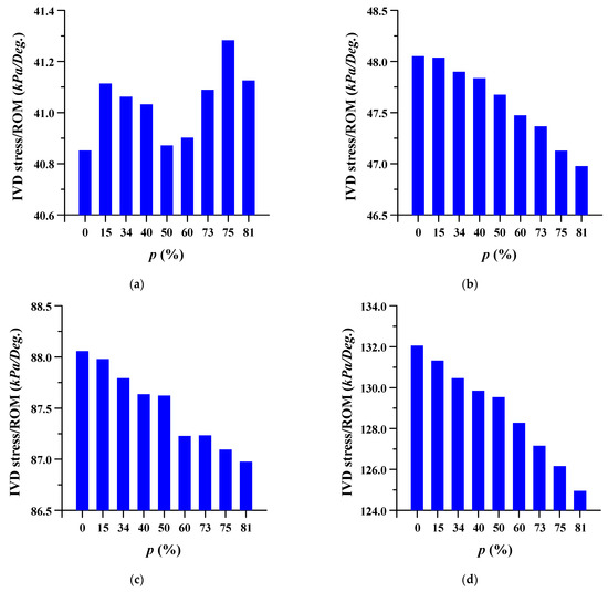
Figure 8.
Equivalent stress per range of motion (ROM) of adjacent intervertebral disc (IVD) of L3-4 at different porosities of the spinal implants in each spinal motion: (a) flexion; (b) extension; (c) lateral bending; and (d) rotation.

Figure 9.
Equivalent stress per range of motion (ROM) of adjacent intervertebral disc (IVD) of L5-S1 at different porosities of the spinal implants in each spinal motion: (a) flexion; (b) extension; (c) lateral bending; (d) rotation.
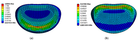
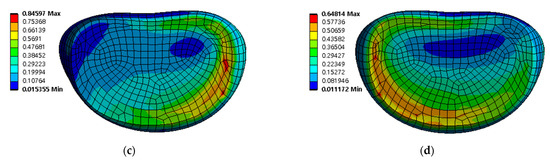
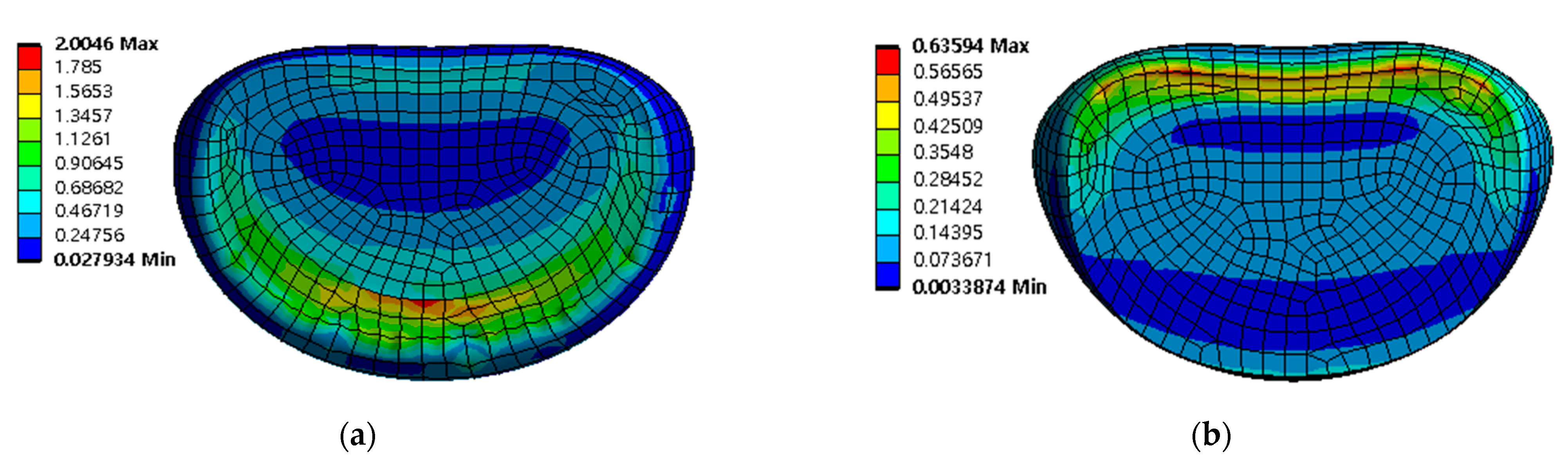
Figure 10.
Equivalent stress distribution of adjacent intervertebral disc (IVD) of L5-S1 at spinal implant porosity 0% in each spinal motion: (a) flexion; (b) extension; (c) lateral bending; (d) rotation (unit: MPa).
3.3. Equivalent Stress at Adjacent Bone of Pedicle Screws and Spinal Cages
The equivalent stress of the pedicle screw and spinal cage adjacent to the bone was evaluated. In the case of pedicle screws, the stress gradually decreased as the porosity of the spinal implant decreased, and when the porosity was lowered beyond a certain porosity, the stress increased again. Conversely, in the spinal cage, the equivalent stress gradually increased as the porosity decreased, and then it decreased again when the porosity was lowered below a certain porosity. This may be attributed to the correlation between the stiffness and strength of the spinal implant and the ROM of the lumbar spine. Figure 11 shows detailed the equivalent stress at adjacent bone of pedicle screws and spinal cages.
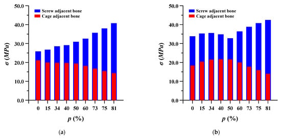
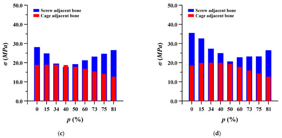
Figure 11.
Equivalent stress (σ) at adjacent bone of pedicle screws and spinal cages at different porosities (p) of spinal implants in each spinal motion: (a) flexion; (b) extension; (c) lateral bending; and (d) rotation.
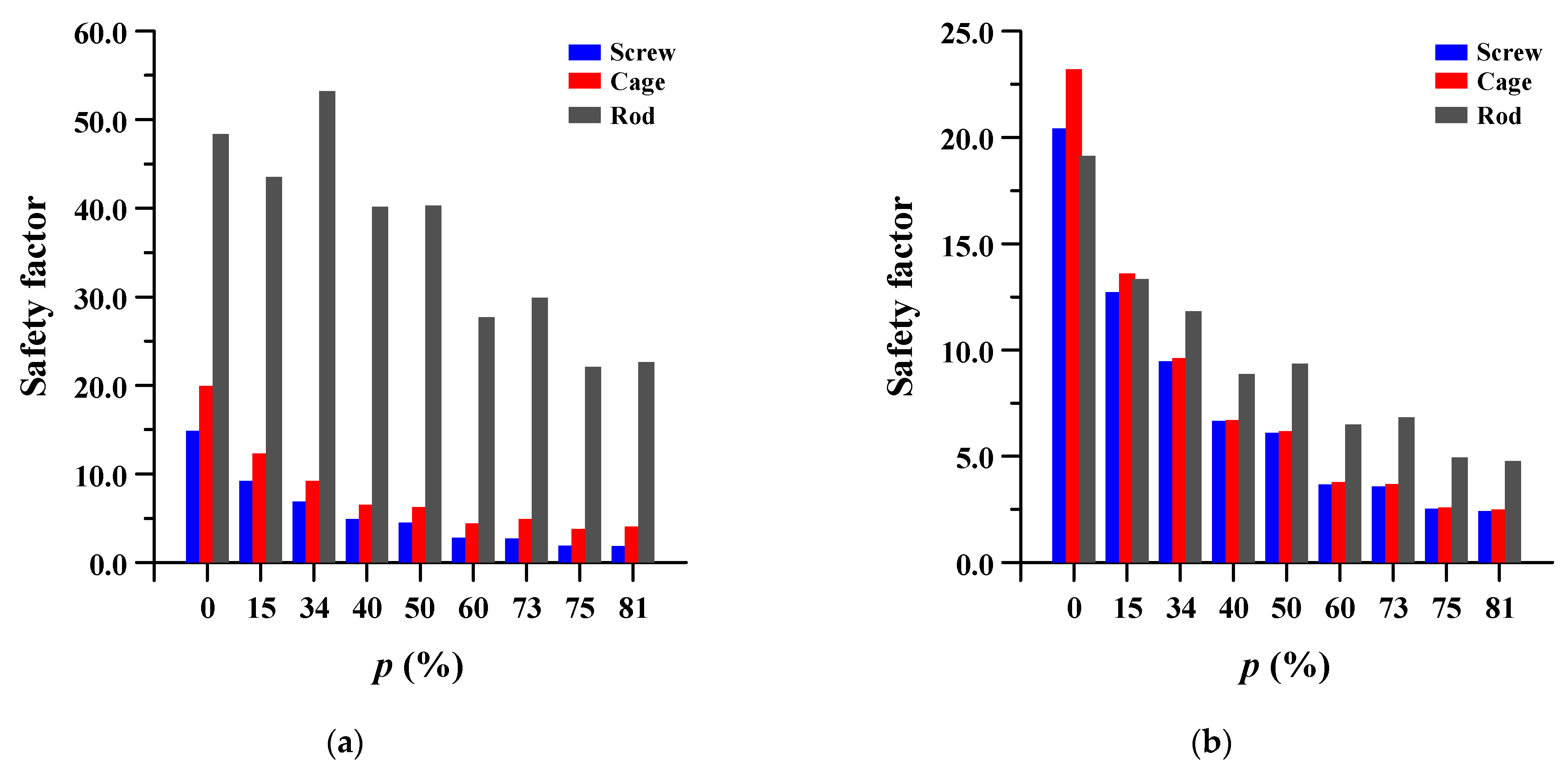
3.4. Safety Factor of Spinal Implants at Different Porosity
The safety factor (equivalent stress/yield stress) was evaluated for the pedicle screw, spinal cage, and spinal rod. Each safety factor of the spinal implant showed a tendency to rapidly increase as the porosity decreased, but even the spinal implant with a high porosity had a safety factor of at least 2.18 (minimum safety factor of spinal cage during rotation). The safety factor and equivalent stress distribution of each spinal implant are shown in Figure 12 and Figure 13, respectively.
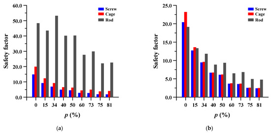
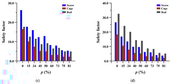
Figure 12.
Safety factor (equivalent stress/yield stress) of pedicle screw, spinal cage and spinal rod at different porosities (p) of spinal implants in each spinal motion: (a) flexion; (b) extension; (c) lateral bending; and (d) rotation.
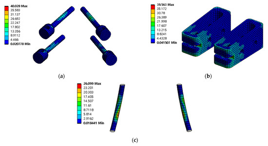
Figure 13.
Equivalent stress (σ) distribution of spinal implants at porosity 50% in extension: (a) pedicle screw; (b) spinal cage; and (c) spinal rod.
4. Discussion
This study evaluated the behavior of each tissue and implant in the spine, when a porous structure was applied to the metal spinal fixation system, used for surgical treatment of patients with spinal diseases, and examined the stability and applicability of the porous structural implant.
Recently, titanium alloys such as Ti–6Al–4V have been mainly used in spinal implants. Metallic materials can be very safe in terms of strength, but they can cause problems such as stress shielding, damage to adjacent bone and tissues, and excessive restriction of spinal behavior due to their excessive elastic modulus, compared with that of the bone. To resolve these issues, studies on porous spinal implants have been conducted. Porous spinal cage has been particularly focused on, and it has been reported that an increase in ROM and a decrease in stress are obtained when the porosity of the spinal cage is increased. However, studies that applied porous structures to pedicle screws and spinal rods have been scarce. Particularly, in clinical trials, fracture of the adjacent bone was caused by the high elastic modulus of pedicle screws and spinal rods. In this study, a porous structure was applied to the entire spinal implant system, including pedicle screws and spinal rod [1,2,3,4,5,6,7,8,9,10,11,12,13,14,15,16,17,18,19,20,21,22,23,24,25].
This study was conducted using ANSYS workbench 2019 R1, a commercial FE analysis program, and FE modeling was performed on lumbar 3 to sacrum 1, where spinal diseases occur most frequently. The spinal disease site was assumed to be between lumbar vertebrae 3 and 4, and a pedicle screw, spinal cage, spinal rod, and bone graft were applied to this site. The microstructure of the porous spinal implant was assumed to be a diamond structure, and the same porosity was applied to all the spinal implants. The microstructure and porosity were obtained from the results of a tensile test by Falkowska et al. Equivalent material properties of porous structures with 15%, 40%, 60%, and 75% porosity were estimated using the Romberg–Osgood formula based on porosities of 0%, 34%, 50%, 73%, and 81%. The spinal implant was evaluated at nine values of porosity, for the behavior of spinal tissues and implants [32,33,34,35,36,37,38,39,40,41].
The behavior of spinal tissues and implants was evaluated by examining the ROM of the spine, intervertebral disc stress per ROM, pedicle screw and vertebral cage adjacent bone stress, and safety factors of each implant. The increase in ROM with increasing porosity indicated that the motor capacity of the spine was improved. However, the stress of adjacent IVDs was reduced, thereby increasing safety. In the evaluation of the adjacent bone stress of the pedicle screw and the spinal cage, the stress of the pedicle screw decreased and increased again with increased porosity, assuming the best performance at a porosity between 40% and 60%. Finally, in the evaluation of the safety rate of implants, the safety factor showed a tendency to decrease rapidly as the porosity decreased, but the safety factor was more than three in all implants with a porosity of 73% or less. Thus, it was estimated that the behavior of spinal tissue and implant was most stable at a porosity between 40 and 60%.
This study is original in that the porous structure was applied to all of the spinal implants, but it is limited in terms of microstructure shape and size, porosity diversity, and detailed behavior of the microstructure; the FE model was also limited to some parts of the lumbar spine. Moreover, the dynamic and fatigue loads were not considered in this simulation.
In the future, these limitations can be addressed to develop clinically applicable spinal implants through continuous research. We will examine various micro-lattices, sizes, and porosities, and conduct structural experiments, rather than simple FE analyses, to obtain their reliability. In the case of the FE model, we will develop a model of the entire spine and perform diverse studies, such as the risk of complications, e.g., kyphosis, due to mechanical properties.
Author Contributions
Conceptualization, C.-S.L., J.S.L. and B.-W.C.; methodology: C.-S.L., J.S.L., B.-W.C. and C.-H.S.; software: J.-S.P. and C.-H.S.; validation: C.-S.L., J.S.L. and B.-W.C.; formal analysis: C.-S.L., J.-S.P. and C.-H.S.; investigation: J.S.L., B.-W.C. and J.-S.P.; writing and original draft preparation: C.-S.L., J.S.L. and C.-H.S.; writing—review and editing: C.-S.L., J.S.L., B.-W.C., J.-S.P. and C.-H.S. All authors have read and agreed to the published version of the manuscript.
Funding
This research was supported by the Basic Science Research Program through the National Research Foundation of Korea (NRF) funded by the Ministry of Science and ICT (NRF-2021R1A2C1013867; NRF-2018R1A2B6007351; NRF-2019R1F1A1062037).
Institutional Review Board Statement
The study was conducted in accordance with the guidelines of the Declaration of Helsinki and approved by the Institutional Review Board of Pusan National University Hospital (IRB No. 2011031097).
Informed Consent Statement
Informed consent was obtained from all subjects involved in the study.
Data Availability Statement
Not applicable.
Conflicts of Interest
The authors declare no conflict of interest. The funders had no role in the study design, data collection and analyses, writing of the manuscript, or in the decision to publish the results.
References
- Warburton, A.; Girdler, S.J.; Mikhail, C.M.; Ahn, A.; Cho, S.K. Biomaterials in spinal implants: A review. Neurospine 2020, 7, 101. [Google Scholar] [CrossRef] [PubMed]
- McAfee, P.; Khoo, L.T.; Pimenta, L.; Capuccino, A.; Coric, D.; Hes, R.; Conix, B.; Asgarzadie, F.; Hamzaoglu, A.; Mirofsky, Y.; et al. Treatment of lumbar spinal stenosis with a total posterior arthroplasty prosthesis: Implant description, surgical technique, and a prospective report on 29 patients. Neurosurg. Focus 2007, 22, 1–11. [Google Scholar] [CrossRef] [PubMed]
- Abumi, K.; Panjabi, M.M.; Kramer, K.M.; Duranceau, J.; Oxland, T.; Crisco, J.J. Biomechanical evaluation of lumbar spinal stability after graded facetectomies. Spine 1990, 15, 1142–1147. [Google Scholar] [CrossRef]
- Kim, Y.-H.; Jung, T.-G.; Park, E.-Y.; Kang, G.-W.; Kim, K.-A.; Lee, S.-J. Biomechanical efficacy of a combined interspinous fusion system with a lumbar interbody fusion cage. Int. J. Precis. Eng. Manuf. 2015, 16, 997–1001. [Google Scholar] [CrossRef]
- Wang, X.-Y.; Dai, L.-Y.; Xu, H.-Z.; Chi, Y.-L. Biomechanical effect of the extent of vertebral body fracture on the thoracolumbar spine with pedicle screw fixation: An in vitro study. J. Clin. Neurosci. 2008, 15, 286–290. [Google Scholar] [CrossRef] [PubMed]
- Li, S.; Li, Z.; Hua, W.; Wang, K.; Li, S.; Zhang, Y.; Ye, Z.; Shao, Z.; Wu, X.; Yang, C. Clinical outcome and surgical strategies for late post-traumatic kyphosis after failed thoracolumbar fracture operation: Case report and literature review. Medicine 2017, 96, e8770. [Google Scholar] [CrossRef] [PubMed]
- Shin, J.K.; Lim, B.-Y.; Goh, T.S.; Son, S.M.; Kim, H.-S.; Lee, J.S.; Lee, C.-S. Effect of the screw type (S2-alar-iliac and iliac), screw length, and screw head angle on the risk of screw and adjacent bone failures after a spinopelvic fixation technique: A finite element analysis. PLoS ONE 2018, 13, e0201801. [Google Scholar] [CrossRef] [PubMed]
- Elias, W.J.; Simmons, N.E.; Kaptain, G.J.; Chadduck, J.B.; Whitehill, R. Complications of posterior lumbar interbody fusion when using a titanium threaded cage device. J. Neurosurg. Spine 2000, 93, 45–52. [Google Scholar] [CrossRef] [PubMed]
- Soroceanu, A.; Diebo, B.G.; Burton, D.; Smith, J.S.; Deviren, V.; Shaffrey, C.; Kim, H.J.; Mundis, G.; Ames, C.; Errico, T.; et al. Radiographical and implant-related complications in adult spinal deformity surgery. Spine 2015, 40, 1414–1421. [Google Scholar] [CrossRef] [PubMed]
- Dailey, S.K.; Crawford, A.H.; Asghar, F.S. Implant Failure Following Posterior Spinal Fusion—Caudal Migration of a Fractured Rod: Case Report. Spine Deform. 2015, 3, 380–385. [Google Scholar] [CrossRef] [PubMed]
- Torstrick, F.B.; Safranski, D.L.; Burkus, J.K.; Chappuis, J.L.; Lee, C.S.; Guldberg, R.E.; Gall, K.; Smith, K.E. Getting PEEK to stick to bone: The development of porous PEEK for interbody fusion devices. Tech. Orthop. 2017, 32, 158. [Google Scholar] [CrossRef]
- Poel, R.; Belosi, F.; Albertini, F.; Walser, M.; Gisep, A.; Lomax, A.J.; Weber, D.C. Assessing the advantages of CFR-PEEK over titanium spinal stabilization implants in proton therapy—a phantom study. Phys. Med. Biol. 2020, 65, 245031. [Google Scholar] [CrossRef]
- Li, C.S.; Vannabouathong, C.; Sprague, S.; Bhandari, M. The use of carbon-fiber-reinforced (CFR) PEEK material in orthopedic implants: A systematic review. Clin. Med. Insights Arthritis Musculoskelet. Disord. 2015, 8, CMAMD–S20354. [Google Scholar] [CrossRef]
- Boriani, S.; Tedesco, G.; Ming, L.; Ghermandi, R.; Amichetti, M.; Fossati, P.; Krengli, M.; Gasbarrini, A. Carbon-fiber-reinforced PEEK fixation system in the treatment of spine tumors: A preliminary report. Eur. Spine J. 2018, 27, 874–881. [Google Scholar] [CrossRef]
- Uri, O.; Folman, Y.; Laufer, G.; Behrbalk, E. A novel spine fixation system made entirely of carbon-fiber-reinforced PEEK composite: An in vitro mechanical evaluation. Adv. Orthop. 2020, 2020, 4796136. [Google Scholar] [CrossRef] [PubMed]
- Brockett, C.L.; Carbone, S.; Abdelgaied, A.; Fisher, J.; Jennings, L.M. Influence of contact pressure, cross-shear and counterface material on the wear of PEEK and CFR-PEEK for orthopaedic applications. J. Mech. Behav. Biomed. Mater. 2016, 63, 10–16. [Google Scholar] [CrossRef] [PubMed] [Green Version]
- Cofano, F.; Di Perna, G.; Monticelli, M.; Marengo, N.; Ajello, M.; Mammi, M.; Vercelli, G.; Petrone, S.; Tartara, F.; Zenga, F.; et al. Carbon fiber reinforced vs titanium implants for fixation in spinal metastases: A comparative clinical study about safety and effectiveness of the new “carbon-strategy”. J. Clin. Neurosci. 2020, 75, 106–111. [Google Scholar] [CrossRef]
- Li, P.; Jiang, W.; Yan, J.; Hu, K.; Han, Z.; Wang, B.; Zhao, Y.; Cui, G.; Wang, Z.; Mao, K.; et al. A novel 3D printed cage with microporous structure and in vivo fusion function. J. Biomed. Mater. Res. Part A 2019, 107, 1386–1392. [Google Scholar] [CrossRef]
- Cao, X.; Duan, S.; Liang, J.; Wen, W.; Fang, D. Mechanical properties of an improved 3D-printed rhombic dodecahedron stainless steel lattice structure of variable cross section. Inter. J. Mech. Sci. 2018, 145, 53–63. [Google Scholar] [CrossRef]
- Sallica-Leva, E.; Jardini, A.L.; Fogagnolo, J.B. Microstructure and mechanical behawior of porous Ti–6Al–4V parts obtained by selective laser melting. J. Mech. Behav. Biomed. Mater. 2013, 26, 98–108. [Google Scholar] [CrossRef] [PubMed]
- Li, F.; Li, J.; Huang, T.; Kou, H.; Zhou, L. Compression fatigue behavior and failure mechanism of porous titanium for biomedical applications. J. Mech. Behav. Biomed. Mater. 2017, 65, 814–823. [Google Scholar] [CrossRef] [PubMed]
- Attar, H.; Calin, M.; Zhang, L.C.; Scudino, S.; Eckert, J. Manufacture by selective laser melting and mechanical behavior of commercially pure titanium. Mater. Sci. Eng. A 2014, 593, 170–177. [Google Scholar] [CrossRef]
- Bai, L.; Zhang, J.; Chen, X.; Yi, C.; Chen, R.; Zhang, Z. Configuration Optimization Design of Ti6Al4V Lattice Structure Formed by SLM. Materials 2018, 11, 1856. [Google Scholar] [CrossRef] [Green Version]
- Yan, X.; Li, Q.; Yin, S.; Chen, Z.; Jenkins, R.; Chen, C.; Wang, J.; Ma, W.; Bolot, R.; Lupoi, R.; et al. Mechanical and in vitro study of an isotropic Ti6Al4V lattice structure fabricated using selective laser melting. J. Alloys Compd. 2019, 782, 209–223. [Google Scholar] [CrossRef]
- Hedayati, R.; Ahmadia, S.M.; Lietaertc, K.; Pourana, B.; Lia, Y.; Weinansa, H.; Ranse, C.D.; Zadpoora, A.A. Isolated and modulated effects of topology and material type on the mechanical properties of additively manufactured porous biomaterials. J. Mech. Behav. Biomed. Mater. 2018, 79, 254–263. [Google Scholar] [CrossRef]
- Kang, I.; Choi, M.; Lee, D.; Noh, G. Effect of Passive Support of the Spinal Muscles on the Biomechanics of a Lumbar Finite Element Model. Appl. Sci. 2020, 10, 6278. [Google Scholar] [CrossRef]
- Wang, X.; Xu, S.; Zhou, S.; Xu, W.; Leary, M.; Choong, P.; Qian, M.; Brandt, M.; Xie, Y.M. Topological design and additive manufacturing of porous metals for bone scaffolds and orthopaedic implants: A review. Biomaterials 2016, 83, 127–141. [Google Scholar] [CrossRef] [PubMed]
- Schmidt, H.; Heuer, F.; Simon, U.; Kettler, A.; Rohlmann, A.; Claes, L.; Wilke, H.-J. Application of a new calibration method for a three-dimensional finite element model of a human lumbar annulus fibrosus. Clin. Biomech. 2006, 21, 337–344. [Google Scholar] [CrossRef]
- Pitzen, T.; Geisler, F.; Matthis, D.; Müller-Storz, H.; Barbier, D.; Steudel, W.-I.; Feldges, A. A finite element model for predicting the biomechanical behaviour of the human lumbar spine. Control Eng. Pract. 2002, 10, 83–90. [Google Scholar] [CrossRef]
- Huynh, K.T.; Gao, Z.; Gibson, I.; Lu, W.F. Haptically integrated simulation of a finite element model of thoracolumbar spine combining offline biomechanical response analysis of intervertebral discs. Comput. Aided Des. 2010, 42, 1151–1166. [Google Scholar] [CrossRef]
- Goh, T.S.; Lim, B.-Y.; Lee, J.S.; Lee, C.-S. Identification of surgical plan for syndesmotic fixation procedure based on finite element method. Appl. Sci. 2020, 10, 4349. [Google Scholar] [CrossRef]
- Dreischarf, M.; Zander, T.; Bergmann, G.; Rohlmann, A. A non-optimized follower load path may cause considerable intervertebral rotations. J. Biomech. 2010, 43, 2625–2628. [Google Scholar] [CrossRef] [PubMed]
- Dreischarf, M.; Zander, T.; Shirazi-Adl, A.; Puttlitz, C.M.; Adam, C.J.; Chen, C.S.; Goel, V.K.; Kiapour, A.; Kim, Y.H.; Labus, K.M.; et al. Comparison of eight published static finite element models of the intact lumbar spine: Predictive power of models improves when combined together. J. Biomech. 2014, 47, 1757–1766. [Google Scholar] [CrossRef] [Green Version]
- Dooris, A.P.; Goel, V.K.; Grosland, N.M.; Gilbertson, L.G.; Wilder, D.G. Load-sharing between anterior and posterior elements in a lumbar motion segment implanted with an artificial disc. Spine 2001, 26, E122–E129. [Google Scholar] [CrossRef]
- Goel, V.K.; Monroe, B.T.; Gilbertson, L.G.; Brinckmann, P. Interlaminar shear stresses and laminae separation in a disc: Finite element analysis of the L3–L4 motion segment subjected to axial compressive loads. Spine 1995, 20, 689–698. [Google Scholar] [CrossRef] [PubMed]
- Falkowska, A.; Seweryn, A.; Skrodzki, M. Strength properties of a porous titanium alloy Ti6Al4V with diamond structure obtained by laser power bed fusion (LPBF). Materials 2020, 13, 5138. [Google Scholar] [CrossRef] [PubMed]
- Huang, Y.P.; Du, C.F.; Cheng, C.K.; Zhong, Z.C.; Chen, X.W.; Wu, G.; Li, Z.-C.; Ye, J.-D.; Lin, J.-H.; Wang, L.Z. Preserving posterior complex can prevent adjacent segment disease following posterior lumbar interbody fusion surgeries: A finite element analysis. PLoS ONE 2016, 11, e0166452. [Google Scholar] [CrossRef] [PubMed]
- Renner, S.M.; Natarajan, R.N.; Patwardhan, A.G.; Havey, R.M.; Voronov, L.I.; Guo, B.Y.; Andersson, G.B.; An, H.S. Novel model to analyze the effect of a large compressive follower pre-load on range of motions in a lumbar spine. J. Biomech. 2007, 40, 1326–1332. [Google Scholar] [CrossRef] [PubMed]
- Dowling, N.E. Mechanical Behavior of Materials, 4th ed.; Pearson: London, UK, 2015; pp. 118–615. [Google Scholar]
- ANSYS Inc. Introduction to Contacts—ANSYS Mechanical Structural Nonlinearities; ANSYS Inc.: Canonsburg, PA, USA, 2010. [Google Scholar]
- ANSYS. ANSYS Help Documentation. 2018. Available online: www.ansys.com (accessed on 5 June 2019).


Publisher’s Note: MDPI stays neutral with regard to jurisdictional claims in published maps and institutional affiliations. |
© 2021 by the authors. Licensee MDPI, Basel, Switzerland. This article is an open access article distributed under the terms and conditions of the Creative Commons Attribution (CC BY) license (https://creativecommons.org/licenses/by/4.0/).