Article

Vibrations of Misaligned Rotor System with Hysteretic Friction Arising from Driveshaft–Stator Contact under Dispersed Viscous Fluid Influences

by
Bernard Xavier Tchomeni
and
Alfayo Alugongo
*
Department of Mechanical Engineering, Vaal University of Technology, Vanderbijlpark 1911, South Africa
*
Author to whom correspondence should be addressed.
Appl. Sci. 2021, 11(17), 8089; https://doi.org/10.3390/app11178089
Submission received: 26 June 2021 / Revised: 18 August 2021 / Accepted: 19 August 2021 / Published: 31 August 2021
(This article belongs to the Section Mechanical Engineering)

Abstract

:
Dynamic analysis of a combination of misaligned rotors, the disturbance of the Cardan joint and the rotor–stator rubbing within a restricted clearance space in a viscous fluid is complex and can result in persistent vibration anomalies that are often misunderstood. It becomes increasingly important to gain some insights into how the transmission of coupled motion responds dynamically under a variety of conditions. This paper introduces an efficient simulation of the misaligned multi-degree-of-freedom rotor’s model, which was developed to predict the transient dynamic behaviours of a driveshaft deflection. The model accounts for tight clearance as a function of contact deformation according to nonlinear Hertzian contact theory. The paper also examines recent research by considering the influence of parameters such as eccentric masses, applied torques and flexible coupling joint perturbation introduced in the proposed rotor system. The simulation results indicated that the viscous fluid surrounding the driveshaft had sufficient torsional flexibility to dampen the rubbing impact to the driven shaft displacement. In addition, the torsional fluctuations of the flexible coupling abruptly increased, and then significantly impacted the vibration of the submerged driveshaft. Parametric studies involving the interconnected rotor models indicated that the effects of fluid on a close-bounds contact area can create partial disturbance reduction. The high rubbing contact is shown to be lost through the Hooke’s joints during power transmission. The speed-frequency spectrum maps provide valuable information on all the modelled excitations over the frequency of the twice-running speed resonance in a viscous medium. Further, nonlinear characteristics are reconstructed through orbit shapes and can be adopted in the condition monitoring of rotors in engineering practice.

1. Introduction

Mechanical driveline systems are employed widely throughout the industrialised world for power transmission. Their applications can be found in automobiles, petrochemical facilities and marine propulsion systems, etc. When it comes to coupling parallel shafts in a fluid medium, high vibrations, mechanical damages and contact friction of specific components are very common, and recurrently lead to premature wear of the operating structures. In practice, a perfect Cardan shaft alignment condition is always present in the maritime and automobile industry. The Cardan shafts (Hooke’s joint) constructed to connect two machines that are offset from each other are often challenging for monitoring due to their size, function and accessibility; this makes their alignment study one of the most commonly misunderstood issues a ship’s operator can experience. In offset shaft systems, disturbances are often produced by a rub-impact between two components in the system or an unbalanced rotating shaft mechanism. Such frictional vibrations begin spontaneously from the reduction of the clearance gap of an unbalanced shaft, which leads to an increase in amplitude until any nonlinear contact effect limit is reached. There are many types of frictional contact in machinery and, in most cases, the impact of the vibration contact poses a hazard to the entire driveline system. The forces acting on the vibrating mechanism are frequently external to the system and independent of the various motions within the system. The authors in [1] considered the dynamics of a Hooke’s joint and a crack-induced parametric excitation model using the wavelet technique to analyse the torsional vibration of a ground vehicle propeller shaft system. Furthermore, a crack-induced excitation was identified in a two-axis model for a propeller shaft. The identification considered the torsional and elasticity of an unbalanced and misaligned shaft system using numerical and experimental techniques [2]. Study of the nonlinear dynamic response of a rotor system with multi-faults including unbalance, asymmetric shaft and angular misalignments were numerically investigated by Didier et al., and the influences of the stochastic fault parameters were analysed using a polynomial chaos expansion method for different kinds and levels of uncertainties. The authors demonstrated that variations in faults such as unbalance, bow and parallel misalignment may affect all of the harmonic components of the rotor system [3]. Following the same idea, Fu et al. studied the dynamic response of a misaligned rotor using a nonintrusive analysis method based on Legendre collocation to consider the uncertainties. The results of the multi uncertainties demonstrated significant influences on all harmonic components of the dynamic responses of the nonlinear vibrations in misaligned rotor systems with interval variables [4]. Xia et al. used a nonlinear dynamic model for a four-wheel-drive vehicle driveline connected by a Cardan joint. In this regard, the authors performed the Lagrange formalism to analyse the vibration of the driveline coupling in the torsional and lateral directions. Their study showed that the second-order vibration and noise are generated by the Cardan joint, and the noise can be decreased effectively by reducing the intersection angle of the Cardan joint [5]. Several studies of flexible Cardan shaft instabilities have been conducted to shed more light on the dynamic behaviour of the lateral and torsional vibration caused by the Cardan joint on a vehicle’s driveline, except for fault diagnosis in the fluid domain. In the available literature, few research works have addressed the study of specific faults in flexible rotor systems operating in a fluid medium. Shimogo and Kazao [6] studied the dynamic response of a cracked elastic shaft under the laminar flow excitations. Their analysis demonstrated that the critical speed and the whirling radius of a rotor decrease with an increase in liquid viscosity between the shaft and the cylindrical wall. In the same order of ideas, works relating to fluid–shaft interaction under the condition of breathing crack and rubs of a flexible shaft under the boundary layer excitation have been reported in [7,8,9,10,11]. Researches on the dynamic response of the misalignment rotor with specific faults exhibiting nonlinearity, such as breathing crack, rub, etc., on the driveline is limited. More importantly, there are discrepancies in the techniques of identifications and findings from different investigators. More so, excitation to the flexible structure and fluid forces are provided using a mathematical model of a rotating shaft in a fluid medium. In these works, excitation to the flexible structure and fluid forces are provided using a mathematical model of a rotating shaft in the fluid medium. Despite the effects of torsional and lateral shaft deformation being considered, the dynamic fluid forces imposed by the fluid on the shaft allowed the identification of the characteristics of the crack.
The authors of [12,13] carried out numerical and experimental investigations on flow-induced vibration in a low Reynolds number and low Mach number flow stream to an external exciting flexible plate. The nonlinear Navier–Stokes equations considered bidirectional fluid–structure interaction aided to calculate the flow field. They found that flow-induced and external excitations greatly influence the dynamic performance of the coupled system in turbulent and unstable flow. For a particular combination of frequency and amplitude of the external excitation, an experimental study of the vibration induced by the flow of an externally actuated flexible structure is reported in [13]. They investigated, experimentally under a wind tunnel, the flow-induced vibration of a harmonically actuated flexible plate in the wake of an upstream bluff body. They observed that with the help of a laser vibrometer, a pressure microphone and a high-speed camera, for a certain range of excitation frequency, the vibration of the plate decreases first, reaches a minimum value and then increases with a rise in external excitation. Similarly, the repeated failure of a flexible rubber coupling in a similar vessel with a Z-drive propeller was investigated in [14] using torsional vibration theory and global torsional vibration. In a power transmission system using a Cardan shaft, such as the propulsion system, the authors concluded that an elastic coupling should be used because it offers more radial flexibility for inhibiting the self-excited torsional vibrations effects. To ensure safe design and reliable operation, numerous studies investigated the dynamic characteristics of misalignment shafts connected to a universal joint in the transmission system. However, nonlinear analysis of the misaligned rotor–stator coupled with fluid forces is still limited due to the difficulties in obtaining the analytical nonlinear model of the misaligned shafts and hydrodynamic forces from the complicated fluid dynamics.
The current trend towards higher speeds performance and driveshafts subjected to torsional, bending and recurrent contact in the fluid medium with any component of the system reinforces the importance of the accurate modelling of rotor-bearing systems. To overcome that difficulty, the present work contributes to the dynamic analysis of a misaligned flexible rotor–stator system subjected to rub effect in a viscous medium. The system is modelled based on the assumptions that the driveshaft during operation must transmit its maximum torque developed by the engine, and must also operate at constant varied speeds and angles between the transmission and the driven shaft. The model consists of a system of five-degree freedoms, four of them associated with the bending of the shafts, and the other linked to the rotating driveshaft. The use of two-dimensional Navier–Stokes equations based on the change in flow field due to the oscillating driveshaft was to establish the hydrodynamic forces. In a parallel effort, a theoretical model of mechanical systems constrained to complex kinematics shocks involving the tangential and normal relative motions in a viscous fluid is proposed. Hence, it is expressed to idealise the nonlinear fluid–rotor–stator interaction. The present work is a numerical simulation in nature; therefore, in conjunction with the analytical analysis, it provides a detailed understanding of the methods to extract rub features in the various working environments using a speed-frequency map. The impact of the study will provide a better understanding of the extraction of rubs faults and the possibility of separating faults that generate similar frequency spectra in a viscous medium using the time-frequency technique for a more reliable misalignment diagnosis. The details of the study are presented as described subsequently. The description of the system and techniques used to establish the complete dynamic model are given in Section 2, Section 3 and Section 4. Section 5 discusses the numerical simulations for estimating the role of the hydrodynamic forces in the dynamic behaviour of the system. Additionally, important features have been presented in the same section using a speed-frequency scheme for solving nonlinear governing equations and separating similar frequency spectra. Conclusively, a detailed flow-induced vibration from externally excited flexible misaligned shafts is illustrated in Section 6.

2. Modelling Approach and Governing Equation

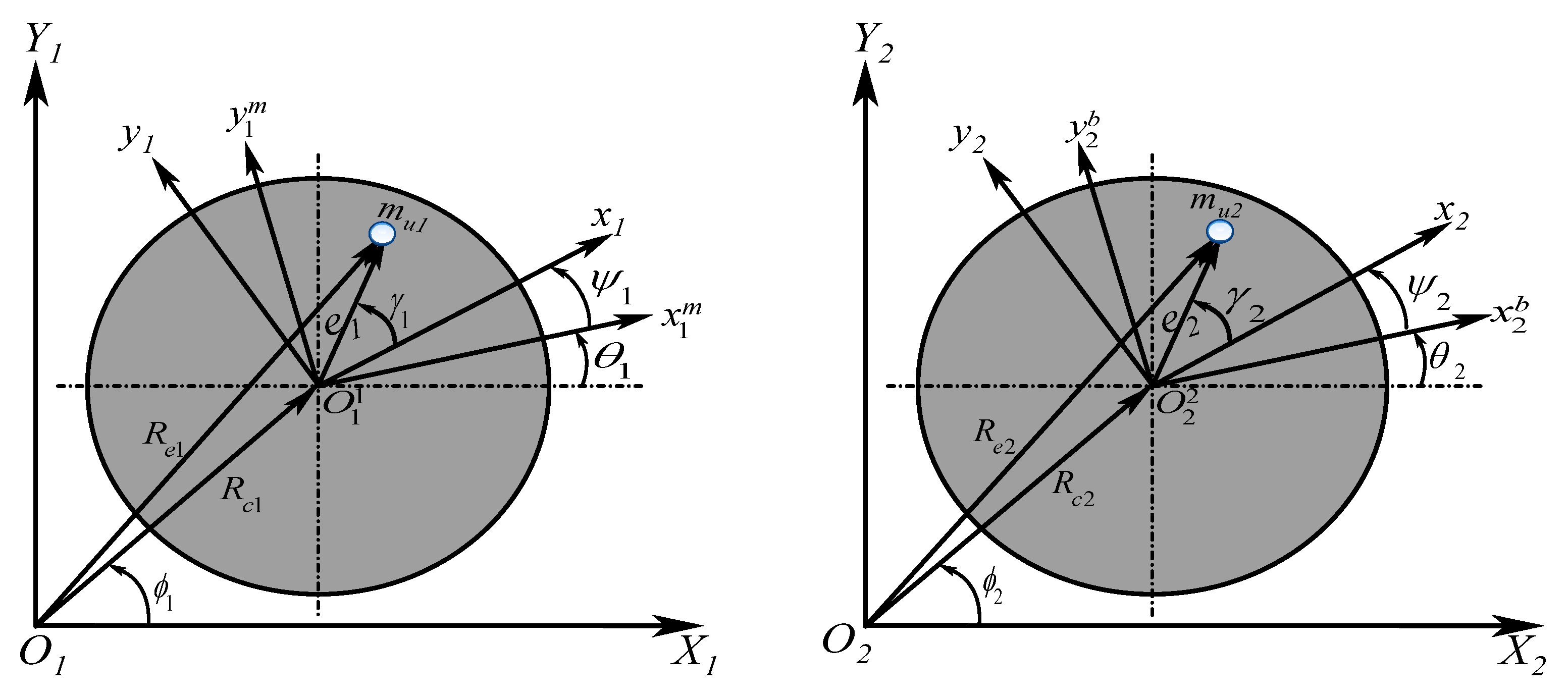
The establishment of the driveshaft–stator contact model in a viscous medium is presented in this section. The fundamental model of rotor lateral and torsional vibration is used to study the mechanisms of impact between a rotating driveshaft and casing (stator) which includes two unbalanced shafts connected by a Hooke’s joint. The twin-rotor system consists of two identical shafts, a driveshaft which is referred to as a motor-shaft and the driven shaft connected to the first shaft by a flexible Hooke’s joint as shown in Figure 1. A front view of the model for the response analysis in the coordinate systems (O1 X1, Y1, Z1) and (O2 X2, Y2, Z2) is indicated in Figure 2.
In the coupled twin-rotor modelling process, the following assumptions are made: (1) The connected twin-rotor system via the Hooke’s joint can be modelled as a Jeffcott rotor system in which the two rotors are simplified into an identical shaft disc with an eccentric mass attached to each disc. (2) The driveshaft system spins around the longitudinal axis Z at a constant angular velocity Ω with an angular misalignment to the driven shaft defined by β . (3) The diameter of a shaft is significantly small relative to its length, the inertias of the discs are not consistent and with the lower rotational motor speed, the gyroscopic effects are therefore neglected. (4) The self-aligned bearings are rigidly supported, viscous damping acts to oppose the movement of the driveshaft-disc system. (5) When rub-impact happens, conditions of viscous fluid deformations are assumed to be elastic. It is also considered that the two eccentric masses m u 1 and m u 2 are attached at a distance e 1 and e 2 of the centre of rotation of each shaft disc’s masses M 1 and M 2 , respectively. The coordinate frames used to develop the model are shown in Figure 2 where the centres of the discs are at the points, x 1 , y 1 and x 2 , y 2 , which are the rotating coordinates attached to the respective centres of the discs.

2.1. Establishment of the Cardan Joint Perturbation Equation

In a proper examination of the proportions of the driveshaft fluctuations and estimation of the maximum driven shaft vibrations caused by the variations in the Hooke’s joint including the angular speed, the motion equations governing the Cardan joint must be established. Such a set of equations is derived in this work using some geometrical and trigonometrical relations between the input and output angular speed θ 2 and θ 1 of the Cardan joint. Assuming that there is no friction between the cross pins of the driving and driven shafts, the vector expressing the motion transmitted between the two shafts can then be written as
θ 2 = ( 1 μ ) θ 1
where μ is a small perturbation parameter that depends on θ 1 . The kinematic relationship between the output motion θ 2 and input θ 1 is given by Seherr-Thoss et al., [15]
tan θ 2 = cos β tan θ 1
where β is the angle of inclination of the secondary shaft. Combining Equations (1) and (2), yields
tan ( 1 μ ) θ 1 = γ tan θ 1
After a series of trigonometric manipulations and for infinitesimal small-angle approximation, the Cardan joint fluctuation leads to
cos β tan θ 1 = tan θ 1 tan ( μ ( θ 1 ) ) 1 + tan θ 1 tan ( μ ( θ 1 ) )
Making the perturbation function μ ( θ 1 ) in Equation (4) the subject yields to
μ ( θ 1 ) = { 1 cos β                                             i f   θ 1 = 0 ( 1 cos β ) tan θ 1 θ 1 [ cos β tan 2 θ 1 + 1 ]           i f   0 < θ 1 mod π , θ 1 0    
For a limited range of μ ( θ 1 ) , Equation (5) will be finite and periodically convergent. Recalling that the equation for Hooke’s joint fluctuation coupling is a function of the driveshaft angular displacement θ 1 and driven shaft curbing β ; therefore, the first derivative with respect to time gives the output driven shaft angular velocity using the chain rule as follows
θ ˙ 2 = d d t ( θ 1 a tan θ 1 ( ( 1 a ) tan 2 θ 1 + 1 ) ) = θ ˙ 1 ( 1 a n ( 1 a ) n 2 + 1 ( n 2 + 1 n 2 ( 1 a ) n ( n 2 + 1 ) ( 1 a ) n 2 + 1 ) )
where n = tan θ 1 and a = 1 cos β . Equation (6) demonstrates that the single Hooke’s joint will produce a periodic nonuniform output velocity even though the input velocity is constant. Considering the perturbation function, the discrete representation of the coupled rotor model is reduced to a system with five degrees of freedom.

2.2. Mathematical Modelling of the System

The inertial reference frames, X1, Y1, Z1 and X2, Y2, Z2, as shown in Figure 2, are considered in this work for the global representation of the lumped mass system. The system equations of motion can be obtained using the Energy principle, where the kinetic energy of the coupled rotor system is expressed as
G = 1 2 ( J M 1 + J g + J M 2 ( 1 g ) 2 ) θ ˙ 1 2 + 1 2 M 1 ( X ˙ 1 2 + Y ˙ 1 2 ) + 1 2 M 2 ( X ˙ 2 2 + Y ˙ 2 2 ) + 1 2 m u 1 R ˙ e 1 T R ˙ e 1 + 1 2 m u 2 R ˙ e 2 T R ˙ e 2
where, R ˙ e 1 and R ˙ e 2 are the velocity vectors of unbalance masses m u 1 and m u 2 , respectively, rotating with the moment of inertia of disc 1 and disc 2 [2]. After manipulation and calculation, the vectors R ˙ e 1 and R ˙ e 2 can be expressed as
R ˙ e 1 = { X ˙ 1 θ ˙ 1 e x 1 sin θ 1 θ ˙ 1 e y 1 cos θ 1 Y ˙ 1 + θ ˙ 1 e x 1 cos θ 1 θ ˙ 1 e y 1 sin θ 1 } R ˙ e 2 = { X ˙ 2 θ ˙ 1 e x 2 sin θ 2 θ ˙ 1 e y 2 cos θ 2 Y ˙ 2 + θ ˙ 1 e x 2 cos θ 2 θ ˙ 1 e y 2 sin θ 2 }
where the pairs e x 1 , e y 2 and e x 2 , e y 2 are components of e 1 = { 1 , 0.....0 } T and e 2 = { 1 , 0.....0 } T representing the locations of m u 1 and m u 2 in their respective disc’s body coordinate systems x 1 , y 1 and x 2 , y 2 , as indicated in Figure 2. Assigning and performing the appropriate substitutions of Equation (8) into Equation (7) leads to the total kinetic energy equation defined by
G = 1 2 ( J M 1 + J g + J M 2 ( μ 1 ) 2 ) θ ˙ 1 2 + 1 2 ( M 1 + m u 1 ) ( X ˙ 1 2 + Y ˙ 1 2 ) + 1 2 ( M 2 + m u 2 ) ( X ˙ 2 2 + Y ˙ 2 2 ) m u 1 e ( sin 2 θ 1 X ˙ 1 cos 2 θ 1 Y ˙ 1 ) θ ˙ 1 m u 2 e ( μ 1 ) ( sin 2 θ 2 X ˙ 2 cos 2 θ 2 Y ˙ 2 ) θ ˙ 1
Following the same formulation, the system potential energy comprises both shafts lateral and the torsional strain energy expressed as
V = 1 2 K 1 T θ 1 2 + 1 2 K 1 X X 1 2 + 1 2 K 1 Y Y 1 2 + 1 2 K 2 X X 2 2 + 1 2 K 2 Y Y 2 2 + 1 2 K 2 T θ 2 2
where K 1 X 1 X , K 1 Y 1 Y , K 2 X 2 X and K 2 X 2 X , are the shaft stiffnesses, K 1 T = K 2 T is the torsional stiffness coefficient associated with the system degrees of freedom K 1 X 1 X = K 1 Y 1 Y = K 2 X 2 X = K 2 X 2 X = K 0 .
The total Rayleigh’s dissipation function is obtained by considering the effect of the damping coefficient, and then expressed as
D = 1 2 C 1 T θ ˙ 1 2 + 1 2 C 1 X X ˙ 1 2 + 1 2 C 1 Y Y ˙ 1 2 + 1 2 C 2 X X ˙ 2 2 + 1 2 C 2 Y Y ˙ 2 2 + 1 2 C 2 T θ ˙ 2 2
where C 1 X 1 X , C 1 Y 1 Y , C 2 X 2 X and C 2 Y 2 Y are the flexural vibration damping of the respective degree of freedom’s damping coefficients, C 1 T = C 2 T is the torsional vibration damping of the first and second shaft, respectively. C 1 X 1 X = C 1 Y 1 Y = C 2 X 2 X = C 2 Y 2 Y = C 0 .

3. The Hydrodynamic Forces and Introduction into the Model and Solution

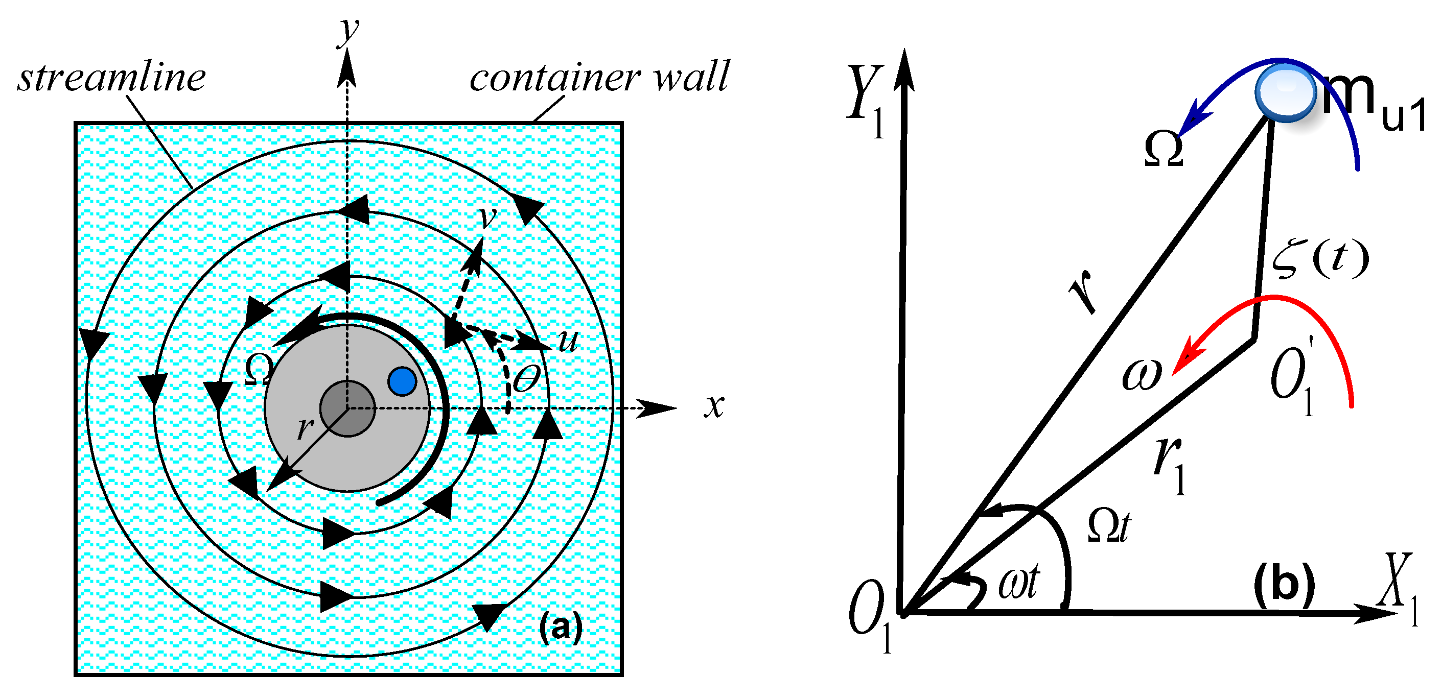
The hydrodynamic forces around the driveshaft are calculated by integrating the pressure distribution over the driveshaft–stator surface. This section establishes all the pressures and fluid forces in the driveshaft–stator gap; they are integrated into the system’s governing equation. With rotation, the flow in the driveshaft becomes helical as depicted in Figure 3a.
The streamline propeller is strongly affected by the speed of the driveshaft and after rotation increases the shear stresses within the incompressible viscous fluid as the tangential boundary layer grows. A complete derivation of the hydrodynamic forces around the rotating shaft has been published in [11], however, the aspect of fluid motion around the eccentric mass is considered in this work to enhance the previous expression of fluid pressures and fluid forces exclusively. The viscous fluid in contact with the driveshaft-disc surface spins at a uniform angular speed ω . The laminar flow around the rotating system in a cylindrical polar coordinates system ( r , θ ¯ , z ) is reduced as
u t = 1 ρ P r + υ [ 2 u u r 2 2 r 2 v θ ¯ ]
v t = 1 ρ r P θ ¯ + υ [ 2 v v r 2 + 2 r 2 u θ ¯ ]
where the Laplacian operator 2 = 2 r 2 + 1 r r + 1 r 2 2 θ ¯ 2 , P , ρ and υ denotes the pressure, density and dynamic viscosity of the fluid. The analysis includes the estimation of the stream function Ψ ( r , θ ¯ , t ) by assuming that the flow velocity component u and v along the radial and circumferential coordinate r and θ ¯ , respectively, are
u ( r , θ ¯ , t ) = 1 r Ψ ( r , θ ¯ , t ) θ ¯ v ( r , θ ¯ , t ) = Ψ ( r , θ ¯ , t ) r
Let the acceleration potential Λ in which gradient gives the acceleration vector equals
Λ ( r , θ ¯ , t ) = υ 2 Ψ ( r , θ ¯ , t ) Ψ ( r , θ ¯ , t ) t
The linearised expression of Equation (16) is obtained by substituting Equations (14) and (15) into Equations (12) and (13), in frame coordinates, r and θ ¯ gives the Navier–Stokes equation in a non-inertial reference frame expressed as
u t = 1 ρ p r + 1 r Λ θ ¯ + u t v t = 1 ρ r p θ ¯ Λ r + v t
This Equation (16) can be resolved by eliminating the pressure term and then writing it as the sum of two-stream functions such that Ψ ( r , θ ¯ , t ) = Ψ 1 ( r , θ ¯ , t ) + Ψ 2 ( r , θ ¯ , t ) where
2 Ψ 1 ( r , θ ¯ , t ) = 0 ( 2 1 υ t ) Ψ 2 ( r , θ ¯ , t ) = 0
The solution of Equation (17) may be written in the form [9]
Ψ 1 ( r , θ ¯ , t ) = f 1 ( r ) sin θ ¯ e i Ω t Ψ 2 ( r , θ ¯ , t ) = f 2 ( r ) sin θ ¯ e i Ω t
where the phase angle θ ¯ = ω t and ω is the angular velocity of the rotating frame relative to the inertial frame and f ( r ) is the amplitude. The partial stream function Ψ ( r , θ ¯ , t ) is expressed as
Ψ ( r , θ ¯ , t ) = [ A r + B K 1 ( r i Ω / υ ) ] sin θ ¯ e i Ω t
where K1 is a Bessel function of the second kind, the constants A and B are obtained from the boundary conditions in [9]. Considering the effect of the fluid around the eccentric mass m u 1 , it is assumed in this work that r ( t ) is a weak function of time; in other words, the simplest approximation for the distance r ( t ) from the centre of the tank filled with a viscous fluid is r ( t ) = r 1 + e ( t ) where r1 is the radius of the free fluid surface, e ( t ) is a low order perturbation function representing the time-varying eccentricity e ( t ) = e x ( t ) 2 + e y ( t ) 2 < R . The fluid’s boundary position around the disc is expressed as
r ( t , θ ¯ ) = r 1 + e x 1 ( t ) cos θ ¯ + e y 1 ( t ) sin θ ¯ = r 1 + ξ ( t )
where ξ ( t ) = e x 1 ( t ) cos θ ¯ + e y 1 ( t ) sin θ ¯ is a perturbation function of the fluid around the eccentric mass, and e x 1 ( t ) and e y 1 ( t ) are the vector e components projected in x 1 , y 1 frame. The velocity components u and v of the fluid at the shaft must be ( r 1 + ξ ( t ) ) Ω e i Ω t parallel to the direction of oscillation and are given in the form
u ( r , θ ¯ , t ) = ( r 1 + ξ ( t ) ) Ω cos θ ¯ e i Ω t v ( r , θ ¯ , t ) = ( r 1 + ξ ( t ) ) Ω sin θ ¯ e i Ω t
where Ω is the frequency of rotor oscillation. The total stream function Ψ ( r , θ ¯ , t ) is expressed, after performing the needed manipulation, in the form
Ψ ( r , θ ¯ , t ) = Ω ( r 1 + ξ ( t ) ) ( ( 2 R K 1 ( k R ) + R 2 k K 0 ( k R ) ) sin θ ¯ e i Ω t 2 K 1 ( k R ) k K 0 ( k R ) )
where K0(kR) and K1(kR) are expressed in terms of Kelvin’s functions. The effect of hydraulic resistance produced by a submerged driveshaft is formulated from a general motion of the liquid pressure as
F ( r , θ ¯ , t ) = L R 0 2 π ( P r r cos θ ¯ P r θ sin θ ¯ ) d θ ¯
where the hydrodynamic radial and pressure distribution are useful parameters that indicate the minimum fluid thickness that lubricates the input shaft. At r = R , the boundary parameters at the driveshaft surface tank walls and bottom are evaluated as
P r r ( r , θ ¯ , t ) = P + 2 μ f l u r | r = R = i R ρ Ω 2 ( r 1 + ξ ( t ) ) cos θ ¯ e i Ω t
p r θ ¯ = μ f l ( v r ) = ρ Ψ 2 t p r θ ¯ ( r , θ ¯ , t ) = 2 i Ω 2 ρ ( r 1 + ξ ( t ) ) K 1 ( k R ) sin ( θ ¯ ) e i Ω t k K 0 ( k R )
where μ f l represents the fluid viscosity; therefore, the hydrodynamic pressure distribution will lead eventually to the hydrodynamic forces acting on the driveshaft–stator, and it is obtained by integrating the pressure distribution over the projected driveshaft length L as
F ( r , θ ¯ , t ) = L R 0 2 π ( P r r cos θ ¯ + P r θ 1 sin θ ¯ ) d θ ¯
It is assumed that the driveshaft angular speed Ω coincides with whirling fluid speed ω and, integrating the first term by parts and using Equations (24) and (25), yields the following result
F ( r , θ ¯ , t ) = i π ρ L R 2 Ω 2 ( r 1 + ξ ( t ) ) e i Ω t ( 1 + 2 K 1 ( k R ) R 2 k K 0 ( k R ) )
The obtained hydrodynamic force acting on the shaft is
F f l u i d ( r , θ ¯ , t ) = ( r 1 + ξ ( t ) ) ( π ρ L R 2 ) Ω 2 ϒ o × [ ( π 4 γ + 4 ln ( 2 ) + 3 4 ln ( R Ω / υ ) cos Ω t + ( 4 γ 4 ln ( 2 ) 3 + 4 ln ( R Ω / υ ) ) sin Ω t ]
Due to the position of the eccentric mass and the geometric centre, the immersed driveshaft rotor has a static unbalance (linear eccentricity-e). The hydrodynamic force component can be reduced over the projected area to
F r e a l ( r , θ ¯ , t ) = m 0 ϒ o ( π ϒ 1 ) Ω 2 r 1 cos Ω t + m 0 ϒ o ϒ 1 Ω 2 r 1 sin Ω t + m 0 Ω 2 e ϒ o ϒ 1 sin Ω t + m 0 Ω 2 e ϒ o ( π ϒ 1 ) cos Ω t
where m 0 = π ρ L R 2 represents the constant mass of the fluid displaced by length L of the shaft ϒ 1 = 4 γ 4 ln ( 2 ) 3 + 4 ln ( R Ω / υ ) and γ is the Euler constant. ϒ o represents the dimensionless partial amplitude of vibration and can be found in [11].
In many cases of flow-induced forced vibration, the response estimation can be broken down into independent equations of motion such as the added mass and the added damping, which greatly affect the characteristics of the structures. The relation between the obtained hydrodynamic forces and the displacements (and accelerations) of the driveshaft, gives the equivalent coefficients. The mass of the viscous fluid is significant since the amount of fluid present between the driveshaft and the stator is considerable for the system to re-establish the equilibrium conditions at each rub-impact. The resulting viscous forces ( F X 1 , F Y 1 ) about the driveshaft centre in the two-dimensional X 1 and Y 1 direction flow, acting on the whirling driveshaft in an unsteady flow are expressed as
F X 1 ( r , θ 1 , t ) = m 0 ϒ o ( π ϒ 1 ) d 2 X 1 d t 2 m 0 Ω ϒ o ϒ 1 d X 1 d t + F f l X 1
F Y 1 ( r , θ 1 , t ) = m 0 ϒ o ϒ 1 d 2 Y 1 d t 2 + m 0 Ω ϒ o ( π ϒ 1 ) d Y 1 d t + F f l Y 1
where the fluid mass and damping coefficients per unit fluid depth represent the inherent flexibility and damping of the viscous film. By applying a spring–damper concept the fluid parameters interacting with the driveshaft are given by the following expressions
M f l X 1 = m 0 ϒ o ( π ϒ 1 ) ;   D f l X 1 = m 0 Ω ϒ o ϒ 1 M f l Y = m 0 ϒ o ϒ 1 ;   D f l Y = m 0 ϒ o Ω ( π ϒ 1 )
F C f l X 1 = m 0 Ω 2 e ϒ o ( π ϒ 1 ) cos Ω t ;   F C f l Y 1 = m 0 Ω 2 e ϒ o ϒ 1 sin Ω t
The effects of the rotation of the fluid around the eccentric mass m u 1 at disc 1 introduce additional unbalanced centrifugal fluid forces to the system, and these forces are denoted by F C f l X 1 and F C f l Y 1 which appear for the first time in this study and act outwards in the radial direction.

4. Contact Region and Excitation Forces Inside the Viscous Fluid

In the presence of the viscous fluid, energy dissipation arises from the contact of the driveshaft with the fixed stator, which results in the undistributed pressure appearing at the interface between the driveshaft and the physical surface. Consequently, Coriolis forces and centrifugal effects increase the pressure drop of the fluid entering the rotor–stator air gap. The collision consists of a period of compression of the fluid when the driveshaft approaches the stator, followed by a period of restitution wherein they separate. Due to the viscoelastic deformations of the parts in contact, fluid resistance to the contact accounts for the energy dissipation, which is schematically modelled here in analogy with a nonlinear spring stiffness KT in conjunction with a parallel nonlinear viscous dashpot Dfl. The point O1 is the geometric centre of the rotor and represents its inertia reference position (X1, Y1). The location of the rotor during the rotation is O12. δ is the radial clearance. θ1= Ω t is the angle between the axis of the rotor and the stator. Based on these assumptions, the dynamic deflection of the rotor along the axis of the stator described by Δ is considered as the dominant effect factor during the rubbing process.
For the rub-impact of driveshaft components without fluid, the tangential rubbing process is described by the Coulomb friction model. When the rubbing process occurs, the restoring forces applied to the stator centre (i.e., tangent to the contact surface), as shown in Figure 4b, are defined in [16]
{ F X 1 = F N cos ϕ + F T sin ϕ F Y 1 = F N sin ϕ F T cos ϕ { F X 1 F Y 1 } = K d s ( Δ δ ) Δ ( 1 λ λ 1 ) { X 1 Y 1 }
where K d s = K 0 K s / K 0 + K s and Δ = ( X 1 r X 1 s ) 2 + ( Y 1 r Y 1 s ) 2 . To avoid surface penetration, it is assumed that the hardness of the stator is higher than that of disc 1 in contact. This nonlinear contact gives a normal contact force that is equal to the force acting on either the spring or the dashpot. For successive compression and restitution, the formulation of the internal forces of the system with viscous element is formulated as
F q = K T q + D f l q ˙
where q = ( X 1 , Y 1 ) is a generalised coordinate. The viscous forces account for the resistance due to the liquid shear flow resulting from the displacing fluid. For a driveshaft moving in a viscous liquid; this is valid in a restraint range of Reynolds number Re < 2 × 10⁴. For the immersed driveshaft approaching close to the casing (stator), the normal and frictional forces can be transformed to the rotor inertia centre to give two extended forces as follows, respectively
{ F C f l X 1 F C f l Y 1 } = ( Δ δ ) Δ [ K T ( 1 λ λ 1 ) { X 1 Y 1 } + m 0 ϒ o ω ( ϒ 1 λ λ ( π ϒ 1 ) ) ( X ˙ 1 Y ˙ 1 ) ]
where K T = K s K d k f l / K s K d + K d k f l + K s k f l , k f l = m o ϒ o ϒ 1 ω 2 , X 1 r = Δ cos ϕ and Y 1 r = Δ sin ϕ .
The variation of the minimum hydrodynamic thickness is illustrated with respect to time, for high input shaft speed and low Reynolds in Figure 5b. Upon substitution of Equations (9)–(11) with Equations (30), (31) and (36) and performing requisite differentiation using Lagrange’s principle, the full system differential equations in each generalized coordinate frame are
[ m θ 1 θ 1 m θ 1 X 1 m θ 1 Y 1 m θ 1 X 2 m θ 1 Y 2 m X 1 θ 1 M 1 + m 1 u + M f l X 1 0 0 0 m Y 1 θ 1 0 M 2 + m 2 u + M f l Y 1 0 0 m X 2 θ 1 0 0 M 2 + m 2 u 0 m Y 2 θ 1 0 0 0 M 2 + m 2 u ] { θ ¨ 1 X ¨ 1 Y ¨ 1 X ¨ 2 Y ¨ 2 } + [ c θ 1 θ 1 0 0 0 0 0 C 0 + D f l X 1 0 0 0 0 0 C 0 D f l Y 1 0 0 0 0 0 C 0 0 0 0 0 0 C 0 ] { θ ˙ 1 X ˙ 1 Y ˙ 1 X ˙ 2 Y ˙ 2 } + [ k θ 1 θ 1 0 0 0 0 0 K 0 0 0 0 0 0 K 0 0 0 0 0 0 K 0 0 0 0 0 0 K 0 ] { θ 1 X 1 Y 1 X 2 Y 2 } = { Q R 1 1 Q R 2 Q R 3 Q R 4 Q R 5 }  
The elements of mass, stiffness and damping matrices in their final forms are
m θ θ = ( J D 1 + J M 1 + m 1 u e 1 2 ) + ( J D 2 + m 2 u e 2 2 ) ( μ ( θ 1 ) 1 ) 2 ;   m θ 1 X 1 = m X 1 θ 1 = m 1 u e sin 2 θ 1 ; m θ 1 Y 1 = m Y 1 θ 1 = m 1 u e cos 2 θ 1 ;   m θ 1 X 2 = m X 2 θ 1 = m 2 u e ( μ ( θ 1 ) 1 ) sin 2 θ 2 ; m θ 1 Y 2 = m Y 2 θ 1 = m 2 u e ( μ ( θ 1 ) 1 ) cos 2 θ 2 ;   c θ 1 θ 1 = C 1 T + C 2 T ( μ ( θ 1 ) 1 ) 2 ;   k θ 1 θ 1 = K 1 T + K 2 T ( μ ( θ 1 ) 1 ) 2 N L θ 1 = ( J D 2 + m 2 u e 2 ) ( μ ( θ 1 ) 1 ) μ ˙ ( θ 1 ) θ ˙ 1 2 + 2 m 1 u e cos 2 θ 1 X ˙ 1 + 2 m 1 u e sin 2 θ 1 Y ˙ 1 + m 2 u e ( sin 2 θ 2 cos 2 θ 2 θ ˙ 1 + 2 sin 2 θ 2 ( μ ( θ 1 ) 1 ) θ 1 θ ˙ 1 ) μ ˙ ( θ 1 ) Y ˙ 2 + 2 m 2 u e sin 2 θ 2 ( μ ( θ 1 ) 1 ) 2 θ ˙ 1 Y ˙ 2   + m 2 u e ( 2 cos 2 θ 2 ( μ ( θ 1 ) 1 ) 2 + sin 2 θ 2 μ ˙ ( θ 1 ) + 2 cos 2 θ 2 ( μ ( θ 1 ) 1 ) μ ˙ ( θ 1 ) θ 1 ) θ ˙ 1 X ˙ 2   N θ = K 2 T ( μ ( θ 1 ) 1 ) μ ˙ ( θ 1 ) θ 1 2   Q R 1 = N L θ 1 N θ 1 + T 1 ;   Q R 2 = F f l X 1 + F C f l X 1 ;   Q R 3 = F f l Y 1 + F C f l Y 1 ;   Q R 4 = T θ 1 ;   Q R 5 = T 2
Besides the forces of the centrifugal fluid, the effects of rotation introduce additional forces into the system, namely Coriolis forces, defined by the vectors N L θ , N θ , which have been obtained by the Lagrangian formalism. The vector of the Carioles couple corresponds to the rotor quadratic velocity excited torque and the secondary shaft elastic interaction with respect to the disturbance through the Hooke’s joint. To investigate the rubbing effects on the vibration properties (deflection and misalignments) in a fluid medium, the system is driven by an electric motor with an oscillatory input torque. The applied torque T θ 1 , treated as an external exciting force, is a major component of the machine thrust and depends on the angular velocity; hence, output torque T 2 will undergo cyclic changes similar to that of the driven shaft velocity θ ˙ 2 [17].
T θ 1 = T 1 sin ( β ) sin 2 θ 2 1 + tan 2 β cos 2 θ 2 = k θ 1 θ 1 ( θ 1 θ 2 ) sin 2 θ 2 1 + tan 2 β cos 2 θ 2  
T 2 = θ ˙ 1 θ ˙ 2 T 1 = θ ˙ 1 θ ˙ 2 k θ 1 θ 1 ( θ 1 θ 2 ) = ( 1 ( 1 a ) n a n 2 + 1 ( n 2 + 1 n 2 a n ( n 2 + 1 ) a n 2 + 1 ) ) 1 k θ 1 θ 1 μ ( θ 1 ) θ 1
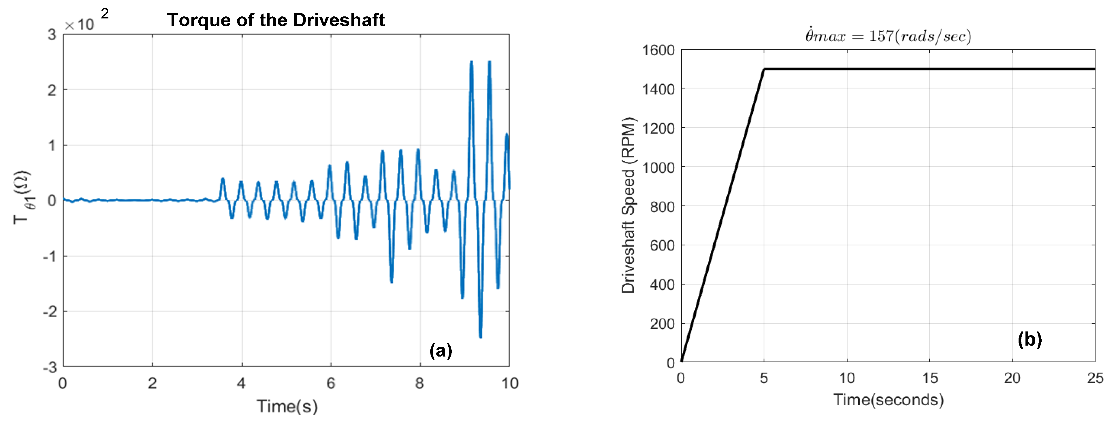
The system response and the whirling orbit of the torque acting on the system at maximum input rotational speed Ω = 1500 rpm, for the intersection angle ( β 0 ) are presented in Figure 6a.

5. Model Parameters and Numerical Simulation

Taking a real Cardan shaft vehicle as an example, the parameters of the dynamic model such as stiffness, damping, mass and inertia, etc., (Figure 1, Figure 3 and Figure 4) are listed in Table 1 and Table 2. The fluid damping, fluid stiffness and centrifugal fluid forces are estimated by Equations (32) and (33). The model of matrix differential Equation (37) is solved by using the model parameters in Table 1 and Table 2. The torque profile resulting from rotor velocity and torque orbits are shown in Figure 6a,b, respectively.
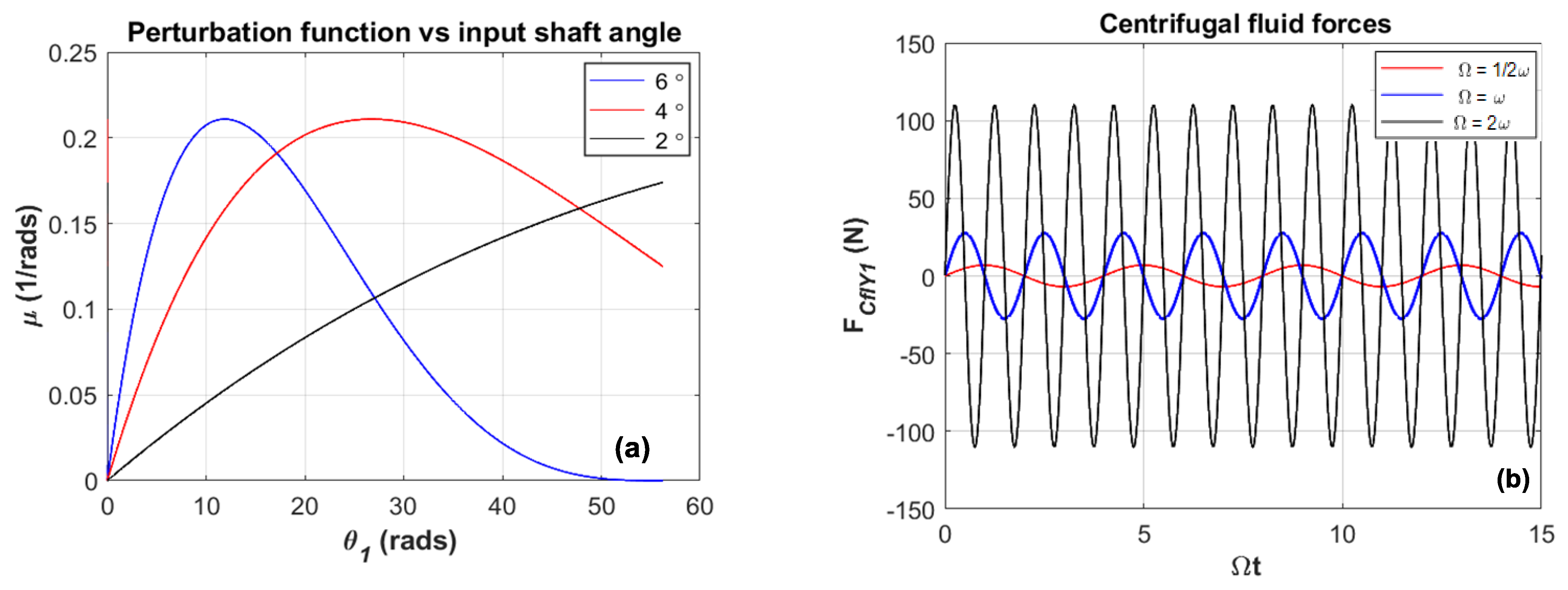
Considering only the torque and angular velocity relationships of the driving motor as they follow from Equations (39) and (40), and increasing linearly the driveshaft angular speed with time (Figure 6a), the applied torque may be required to vary unrealistically. A complete and accurate picture of the transition situation is obtained with a fairly straightforward analysis. The displayed result is likely to be valid as long as the operational driveshaft speed range investigated is below the maximum (Figure 6b). Moreover, Figure 5a indicates that for various shafts’ inclination angle β > 2, there is a linear relationship between the phase input shaft angle and the joint perturbation function on which disturbance has a relatively significant effect when β increases.
Equation (33) provides the time history of the reactive centrifugal fluid forces acting around the eccentric unbalanced disc 1 at various driveshaft speeds, as illustrated in Figure 5b. The profile of the centrifugal forces in the vicinity of disc 1 shows that when the rotating speed is linearly proportional to a critical value, the combination of disc and the incompressible liquid cause the formation of a harmonic sinusoidal fluid profile that is strongly dependent on the input rotational speed (Figure 5b). Thus, it is necessary to analyse the time-varying nature of the coupled systems partially immersed in a viscous fluid and to simulate the motion of the shafts during motion transmission.

5.1. Vibration Analysis of the Unbalanced Rotors System

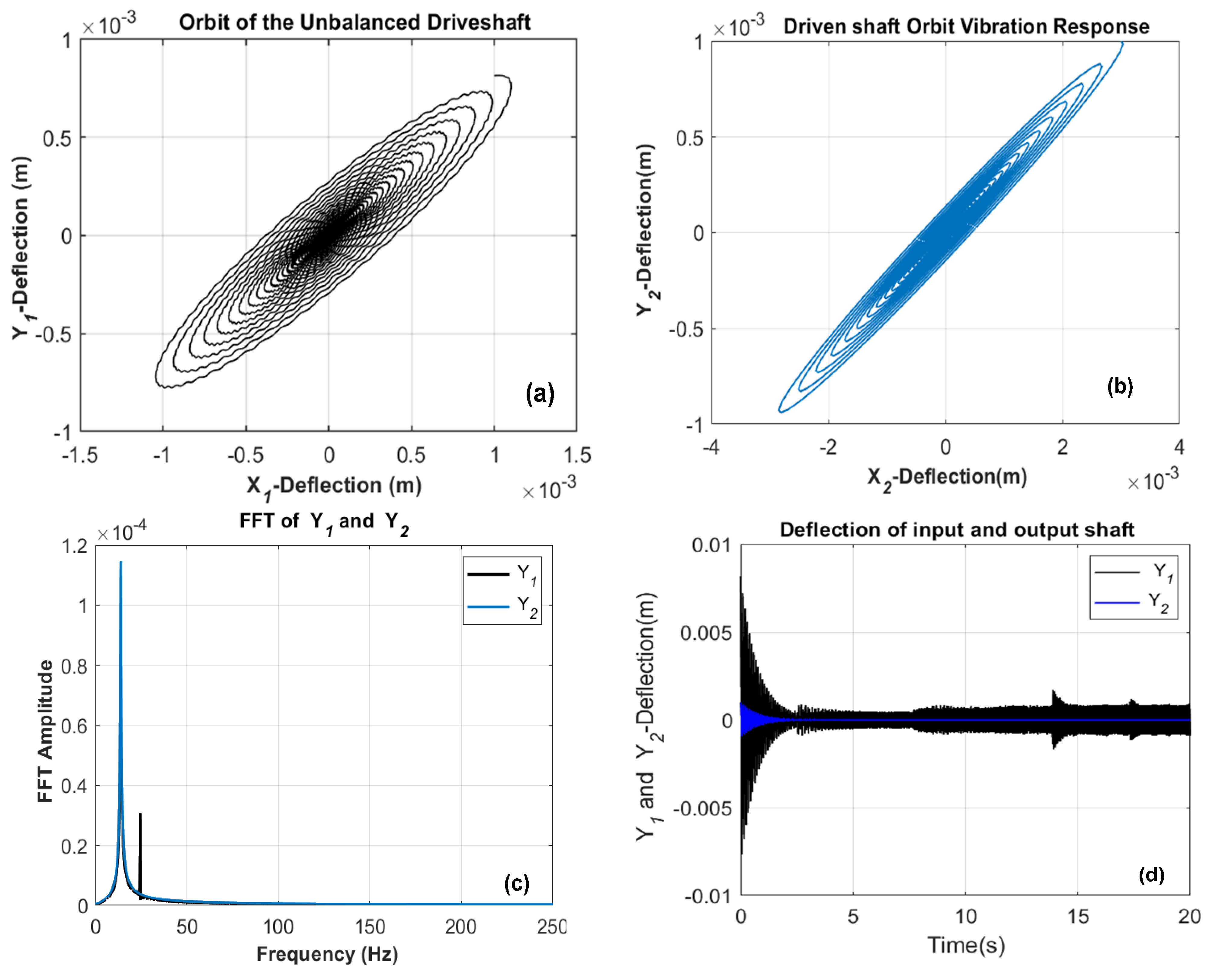
The first dynamic response of the misaligned Cardan shaft is performed. To validate the proposed model in this study, the parameters for the numerical simulation are chosen to be the same as those of the experiment in [10], and the proportionality between ω and Ω is maintained for a wide range of Ω, which is the threshold (ω = Ω). To illustrate the numerical results, the following plots in Figure 7 and Figure 8 are used. As the engine runs, the elliptical orbits of the driveshaft fluctuate with a change in shape (the waveform becomes disturbed closer to the critical speed). The orbital trajectories of the centre of the rotors in a steady state with some regular and intermittent loops are orbitally stable (Figure 7a,b). The operating point of the driven shaft is close to the limit of stability compared to the previous study on the balanced twin-rotor system in [2]. The frequency analysis (Figure 7c) is confirmed in both shafts, the presence of the main rotational frequency from 0 to 50 Hz and the frequency multiple of the rotation frequency of the drive shaft. Note that the value of the over-synchronous frequency is shifted, which reflects the action of the engine power on the dynamic behaviour of the unbalanced driveshaft.
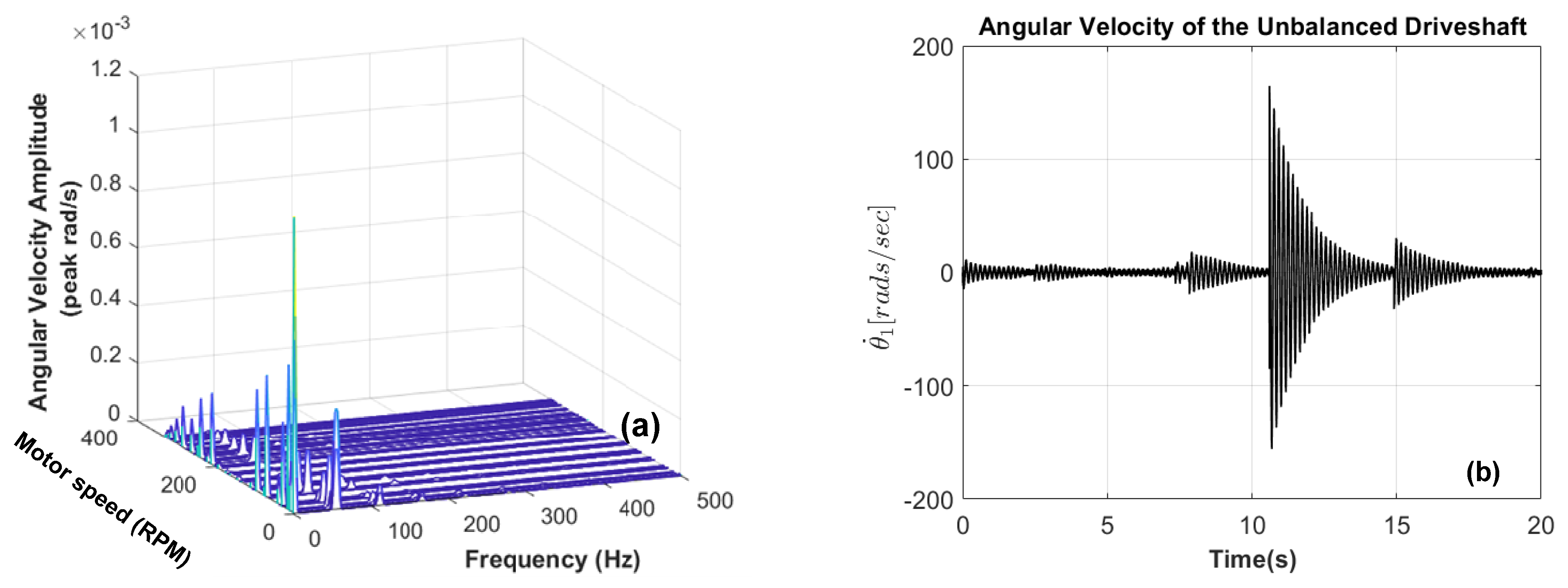
The comparative temporal analysis in the direction of the force of gravity Y1, Y2 (Figure 7d) shows the phase difference between the two shafts. As the speed increases, the system displacement response shows that the lateral deflection keeps on attenuating until constant vibration. However, for each period, the movement is identical in the case of the first shaft and practically nonlinear in the case of the output shaft with larger amplitudes. The system torsional deflection in Figure 8b shows the complexity of torsional deflection in the operating period of vibration. Conversely, after a transient vibration process with a much higher amplitude, it gradually becomes stable and the amplitude of vibration continues to subside until torsional vibration stops.
This implies that the input excitation of the motor is responsible for strong torsional vibration and is a valuable approach to control the torsional vibration of the driveshaft. This is inferred in the following analysis: a time-frequency method is applied for measuring driveshaft fluctuation based on the engine speed and the shaft oscillation frequency, which does not involve any mechanical forces except for the measured unbalance. The measured pickup signal spectrum was analysed and yielded the driveshaft spectral response. The proposed method suitable to different system conditions is tailored for various modes of operation (unbalance, friction and fluid friction). The 3-D speed-frequency spectrum results presented in Figure 8a shows the effect of operating speeds on FFT plots to analyse the system behaviour. The frequency responses to the initial unbalance generated a randomly appearing subsynchronous frequency scattered around the resonance frequency, which reflects the action of the motor on the dynamic behaviour of the unbalanced driveshaft. It can be seen that the amplitude of instantaneous frequency is about 50 Hz and its fluctuating frequency is in the range of 0–100 Hz, which is consistent with the set parameters as shown in Figure 7c. The frequencies are more important in amplitude and present around the main frequency of rotation at a considerable level of disturbance (unstable vibration).
This section finds that the centrifugal forces cause high vibration amplitude at a frequency equal to 1× rpm in spectral data and waveform in the time domain of the shaft’s lateral deflection. Misalignment of couplings typically produces raised frequencies at 1× rpm and 2× rpm that are not essential to distinguish unbalance from misalignment. The analytical result of the unbalance in the 3-D speed-frequency model has been successfully applied to capture the main features of the behaviour of the shafts whose resulting subharmonics peaks are not caused by the rotor natural frequencies only. A further simulation was performed for the rotor’s system with some rub contact in a viscous fluid.

5.2. Vibration Response of the Coupled System with Rubbing Fault

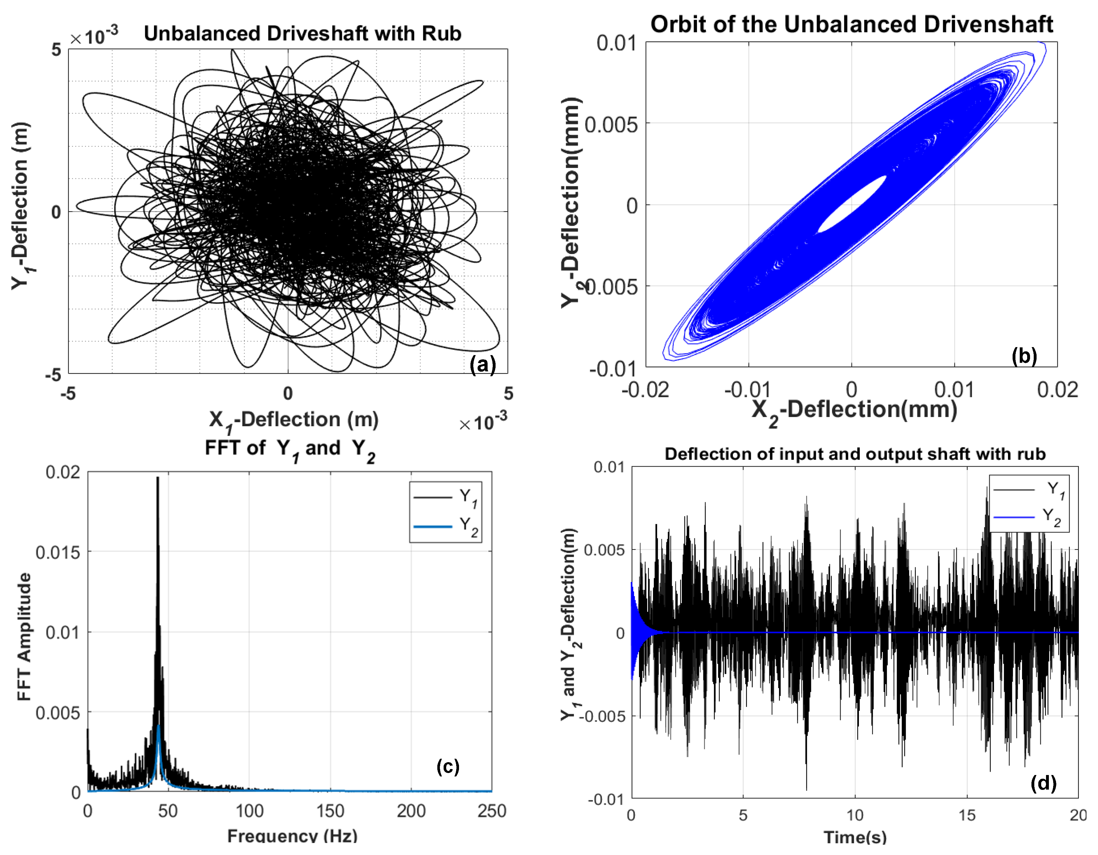
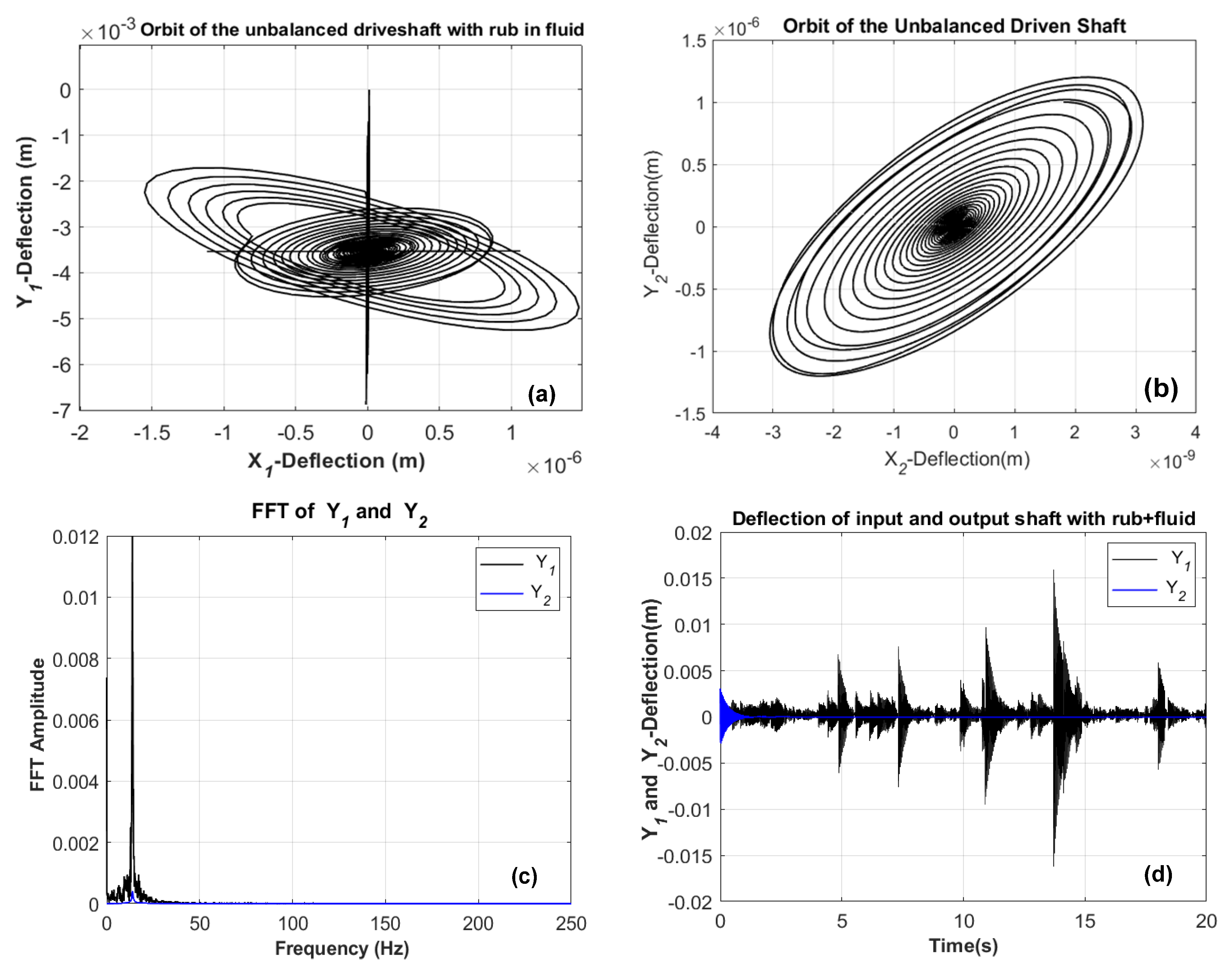
For the multi-faults case (i.e., unbalance, misalignment and rotor–stator rub coexist), the selection of the clearance was completed with an approximation of the realistic friction of the rotor into the stator wall that takes into account the local nonlinear deformations proposed in Equation (36). The dynamic response in orbit patterns, lateral direction and its FFT spectral are shown in Figure 9. As another parameter of study, the orbit shapes revealing the contact between the rotor and the stator of each shaft varied from 5.127 × 10 3 m for the driveshaft to 1.127 × 10 2 m for the driven shaft in various amplitude levels, as shown in Figure 9a,b. As the contact stiffness increased, the orbits of the driveshaft fluctuated highly with multiple rebounds represented by the irregularity of inside loops (Figure 9a), which causes the disturbing orbit to diverge.
However, the driven shaft orbit only increases in amplitude with tight and regular circular loops. As the contact stiffness increases, the critical speeds of both shafts also increase in frequency and amplitude. From the above plots, as illustrated in Figure 9c, it can be seen that there is an increase in the critical speeds of both shafts when recurring frictional contact occurs, leading to several fluctuating peaks around the main frequency. The higher harmonic resonance at 1× order (47.21 Hz) can be observed in the two unbalanced rotors. However, it is worth mentioning from the FFT spectral plot that the higher sup-harmonic frequencies, for example, 2×, 4×, 6×, etc., along with the 1/2× subharmonic, which usually arise due to the rubbing presence as indicated in [10,18], do not appear in this case. It is evident that the decomposition by FFT is not satisfactory enough as some irregular and imprecise fluctuations exist around the critical frequency levels. Figure 9d illustrates the impact of contact on driveshaft deflection by the rise of compressed low frequencies with subsynchronous broadband noise related to rubbing. There is a significant influence of the coupling joint on the overall dynamic characteristics of the connected rotor system where the monitoring of the waveform and frequencies vibration of the driven shaft vibration disappears significantly.
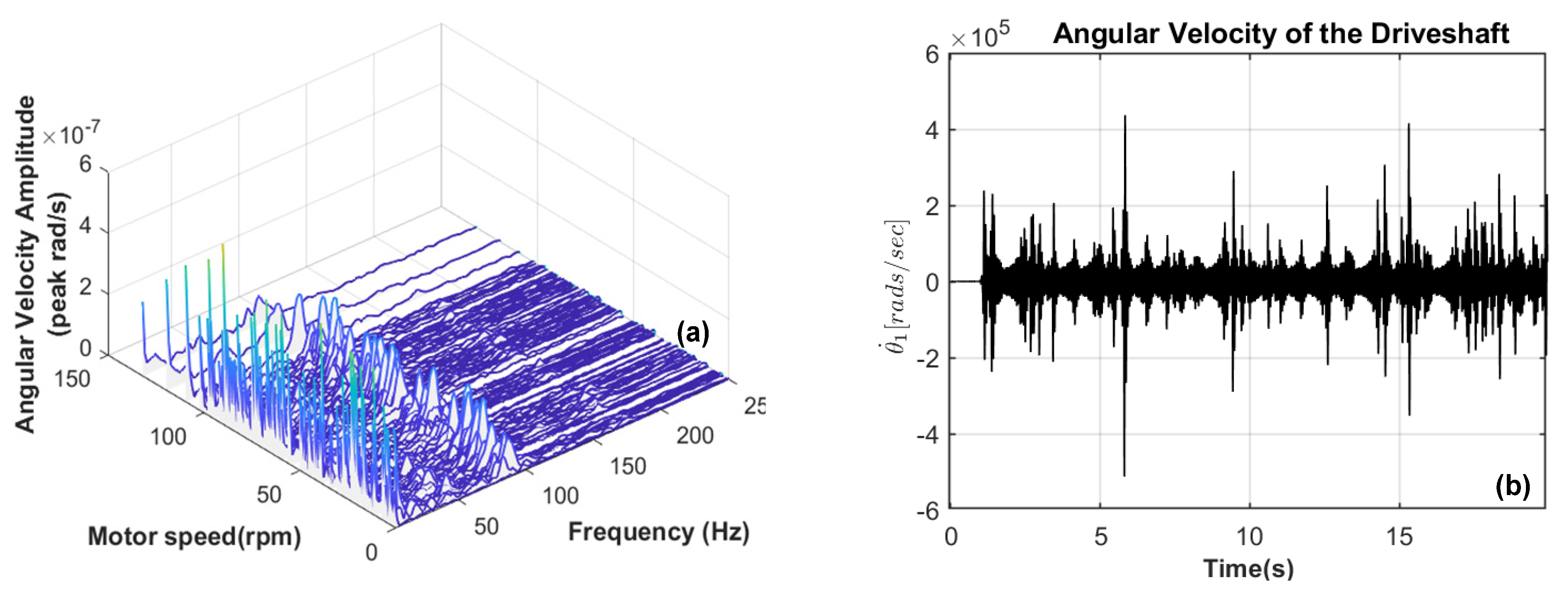
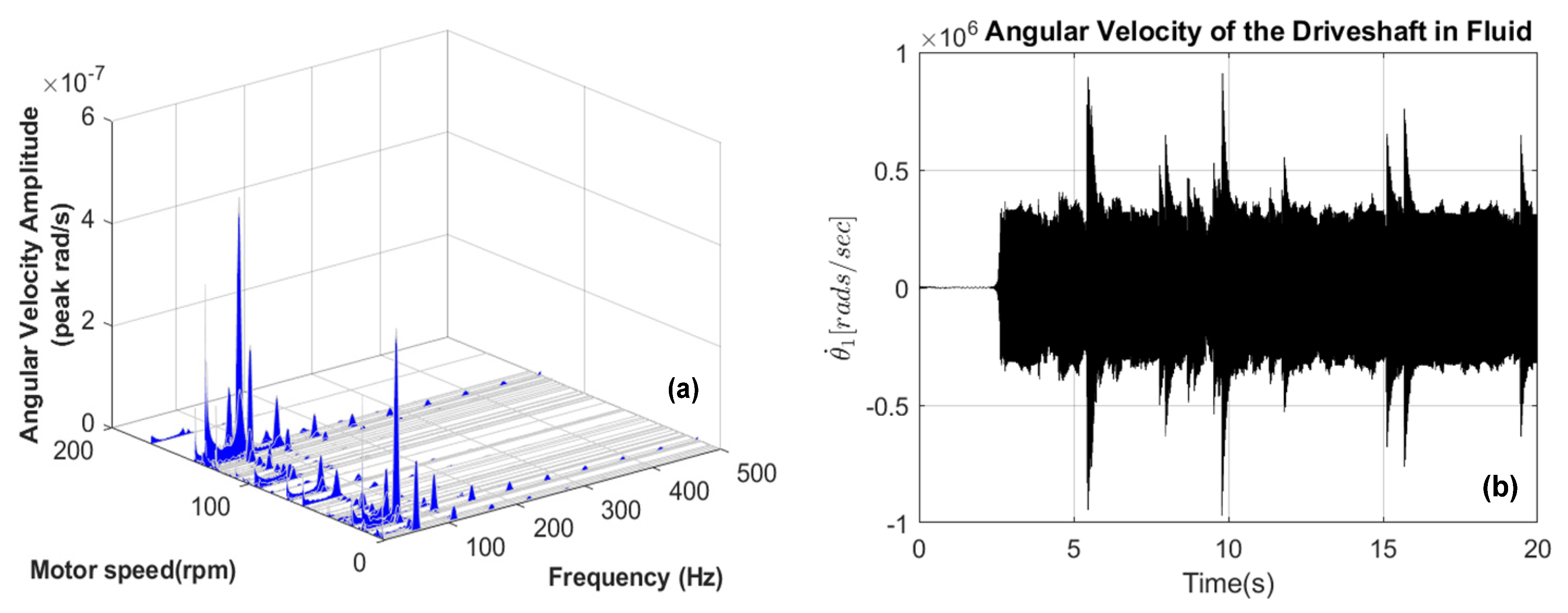
From the components of the 3-D speed-frequency spectrum, the phenomenon of rotor–stator contact can be found in the marginal spectral and peaks distribution (Figure 10a). However, there are a few complex interference components (e.g., the embraced part by the lightly blue peaks line at the starting operation (10 Hz) in Figure 10a), introduced by the unbalance excitation. The higher frequencies observed at the frequency above 50 Hz are excited by misalignment and contact rubbing. These observations of accumulated peaks of the frictional driveshaft are also seen in the marginal spectral in Figure 9d. The angular velocity profile of the driveshaft shows approximate, periodic occurrences of low excitation peaks at higher amplitudes as the characteristics of the rub (Figure 10b). Moreover, it is visible that there exist considerable lags over time and periods of rub occurrences between the FFT spectrum (Figure 9c) and the 3-D speed-frequency (Figure 10a) due to the inherent drawbacks in the coupling joint (misalignment). The results of this section demonstrate that the occurrence of shocks due to the reduction of lateral clearance of the driveshaft–stator rubbing is the specific source of noise that generates irregular operation of the drive unit and contributes to the abrupt variation in frequency vibration (change in angular velocity during one revolution). Aperiodic excitations, such as recurrent shock, centrifugal fluid forces and the unbalance of each shaft, are considered in the next sections.

5.3. Influence of Fluid Forces on the Vibration Response of the Rubbing Coupled System

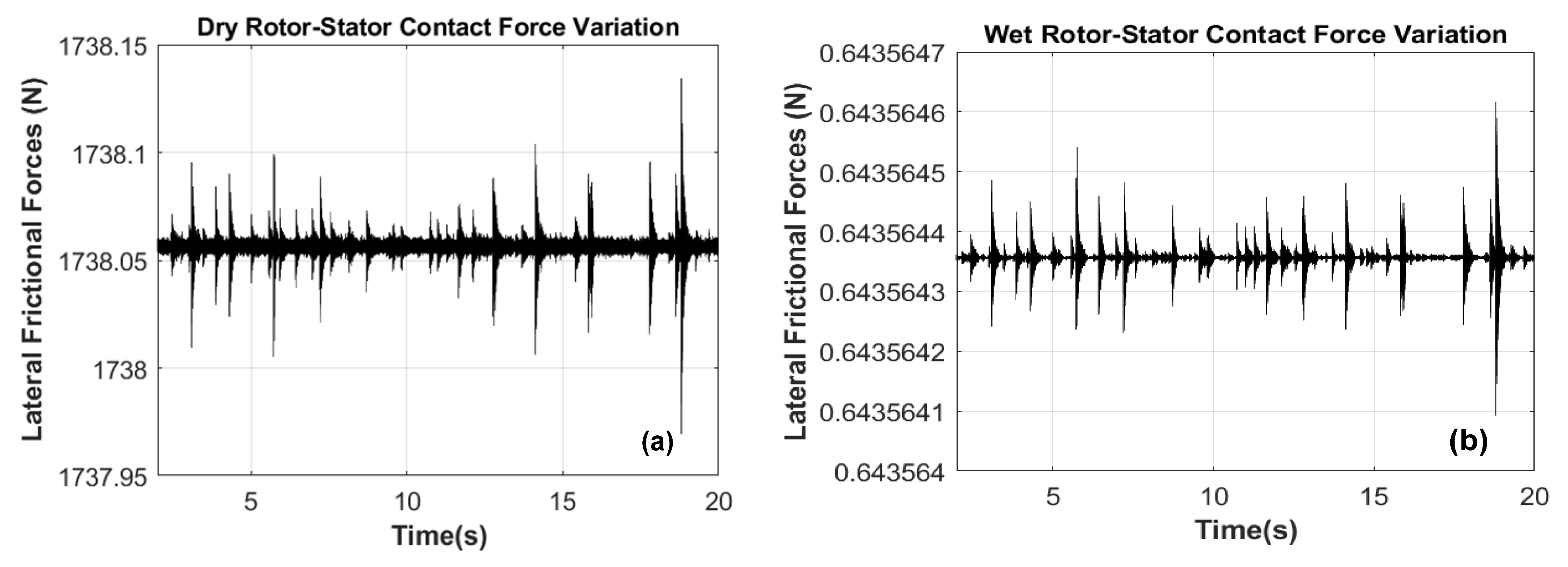
Based on the fundamental assumption that the mass of fluid surrounding the driveshaft always shows laminar flow behaviour dependent on the rotational speed of the input shaft, to avoid having a turbulent effect, the system response is simulated with the propeller shaft speed equal to twice the excitation frequency of the fluid in motion ( Ω = 2 ω ). In the case of the driveshaft immersed in liquid, the responses of the fluid-rotor system become more complicated when combining the nonlinear fluid forces with the nonlinear rotor–stator impact force. External damping fluid has the effect of reducing the system vibration response and changes aperiodically the fluid force’s amplitudes that arise during driveshaft excitation (Figure 11a,b).
The mutual interaction of the mass of fluid and the lateral-torsional motion becomes important for supercritical speeds, while the transition deflections are reduced, especially when the small-diameter shafts and the influence of torque loads are involved. Despite the presence of external damping in the system, the simulation in Figure 12a shows an even stronger fluctuating vibration generating two maximum circular orbit responses at a critical speed, which causes the circular orbit to attenuate.
However, the natural frequency of the rotating driven shaft generates an elliptical orbit, which in Figure 12b does not diverge, indicating that the rotor vibration is effectively suppressed by the coupling joint. It was mentioned in Section 5.1 that the classical critical speed is excited by the unbalanced mass. However, it is observed from Figure 12c that for isotropic rotors, the fluid effect may predict two disturbed regions; one is, in particular, above the critical speed of the rotor’s system and the other is below the critical speed. Adding external damping fluid makes the system more stable (Figure 12d) and can be an effective method of suppressing the strong excitation of the driveshaft–stator rubbing motion in certain cases. Figure 13a shows the characteristics of periodic motion in a viscous fluid at Ω = 30 rad/s through motor speed, frequency spectrum and amplitude. All of the modelled excitations of the driveshaft can be seen in the simulated spectrum maps. With increasing rotational speed, the system passes through a critical speed at ω = 120.6 rad/s and enters regular motion. The amplitude of each frequency component varies nonlinearly and, at a certain speed, there is a continuous spectrum component evident in the three-dimensional spectrum. Contrary to the results in [5], the vibration response demonstrated that the second-order vibration and noise generated by the Cardan joint can be decreased effectively by considering the effects of the fluid forces.
In summary, nonlinear fluid forces have an important influence on the stable operation and dynamic characteristics of the driveshaft system. Usually, very low vibration amplitudes are required over a large range of exciting forces and frequencies to keep dynamic stresses, noise, fatigue and other effects to acceptable levels. Some periodic forces are harmonic but, even if they are not, they can be represented as a series of harmonic functions using time-frequency spectrum analysis techniques. It can be seen from the results that the amplitude of both shaft’s system vibration response decreases and changes aperiodically in the fluid domain. Besides the harmonic peaks multiplication components, the continuous frequency components also appear, and the axis orbit of the system is disordered. Because of this effect, the response of the structures and dynamic systems subjected to harmonic exciting forces and motions is studied.

6. Conclusions

In this paper, a model of rotors coupled by a flexible Hooke’s joint taking with multiple nonlinear factors is considered. The complex nonlinear dynamic behaviour of the coupling rotor system, partially immersed in a viscous fluid, is studied. The influence of the applied torque excitation unbalances, misaligned shafts and input rotor–stator rubbing on the dynamic characteristics of the driveshaft is analysed during the motion’s transmission. The following conclusions are drawn from the study:
  • The normal operation of the rotating machine results from an appropriate torque/load unbalance and consists of the main rotative motion of the driveshaft performed with an appropriate rotational speed. This main motion of unbalanced rotors was accompanied by a limited level of lateral/torsional vibrations of both rotors and a limited level of excitation of nonstationary (rotating) parts.
  • With continuous rubbing contact, the state of motion of the system becomes more complex; the stable region first increases and then almost leads to a chaotic state. The complex and aperiodic motion frequently alternate, and the amplitude of the response gradually increases.
  • When centrifugal fluid forces exist, the response of the coupling system displays many obvious discontinuous amplitude jumps. As the speed variation increases, the system transits from an almost chaotic state to aperiodic motion at an acceptable rotating machine speed.
  • The relative differences of the coupled system can be caused by the rotational speed increment. This means that, most likely, the exact resonance frequency of the rotor system in the viscous fluid is well hit with a diminished amplitude from the real resonance peak.
  • The Hooke’s joint significantly influences the overall dynamic characteristics of the connected rotor system where the monitoring of the highest vibration motion of the driveshaft to the driven shaft is drastically damped.
  • The 3-D frequency spectrum profile is a more efficient tool than the FFT to reveal the nonlinear and nonstationary nature of the excitation frequencies produced by the driveshaft in a fluid medium whose estimation of speed and frequency are more localized for multiple rotor faults.

Author Contributions

The topic of this research is conceptualized by B.X.T. and A.A.; Formal analysis is performed by B.X.T.; The first version manuscript is prepared by B.X.T.; this version of the manuscript is read, approved and substantially contributed to by B.X.T. and A.A. All authors have read and agreed to the published version of the manuscript.

Funding

This research received no external funding.

Data Availability Statement

Not applicable.

Acknowledgments

This work is based on the research supported in part by the Vaal University of Technology (VUT), South Africa, through the Department of Higher Education and Training University Capacity Development Grant.

Conflicts of Interest

The authors declare that they have no known competing for financial interests or personal relationships that could have appeared to influence the work reported in this paper.

References

  1. Alugongo, A.A. Parametric excitation and wavelet transform analysis of a ground vehicle propeller shaft. J. Vib. Control. 2014, 20, 280–289. [Google Scholar] [CrossRef]
  2. Tchomeni, B.X.; Alugongo, A. Theoretical and experimental analysis of an unbalanced and cracked cardan shaft in the vicinity of the critical speed. Math. Model. Eng. 2020, 6, 34–49. [Google Scholar] [CrossRef] [Green Version]
  3. Didier, J.; Faverjon, B.; Sinou, J.J. Study of the non-linear dynamic response of a rotor system with faults and uncertainties. J. Sound Vib. 2012, 331, 671–703. [Google Scholar] [CrossRef] [Green Version]
  4. Fu, C.; Yang, Y.; Lu, K.; Gu, F. Nonlinear vibration analysis of a rotor system with parallel and angular misalignments under uncertainty via a Legendre collocation approach. Int. J. Mech. Mater. Design. 2020, 16, 557–568. [Google Scholar] [CrossRef]
  5. Xia, Y.; Pang, J.; Yang, L.; Zhao, Q.; Yang, X. Nonlinear numerical and experimental study on the second-order torsional and lateral vibration of driveline system connected by Cardan joint. J. Vib. Control. 2020, 26, 540–551. [Google Scholar] [CrossRef]
  6. Shimogo, T.; Kazao, Y. Critical speed of rotor in a liquid. Bull. JSME 1982, 25, 277–283. [Google Scholar] [CrossRef] [Green Version]
  7. Ibrahim, R.A.; Latorre, G. Experimental investigation of dynamic parameters of viscous fluids in unsteady flow. J. Press. Vessel. Technol. 1988, 110, 29–35. [Google Scholar] [CrossRef]
  8. Behera, R.K.; Parhi, D.R.; Sahu, S.K. Vibration analysis of a cracked rotor surrounded by viscous liquid. J. Vib. Control. 2006, 12, 465–494. [Google Scholar] [CrossRef] [Green Version]
  9. Ibrahim, R.A. Liquid Sloshing Dynamics: Theory and Applications; Cambridge University Press: Cambridge, UK, 2005. [Google Scholar]
  10. Tchomeni, B.X.; Sozinando, D.F.; Alugongo, A.A. Influences of hydrodynamic forces on the identification of the rotor-stator-rubbing fault in a rotating machinery. Int. J. Rotating Mach. 2020, 2020, 1–18. [Google Scholar] [CrossRef]
  11. Tchomeni, B.X.; Alugongo, A.A. Modelling and numerical simulation of vibrations induced by mixed faults of a rotor system immersed in an incompressible viscous fluid. Adv. Mech. Eng. 2018, 10, 1687814018819341. [Google Scholar] [CrossRef]
  12. Purohit, A.; Darpe, A.K.; Singh, S.P. Experimental investigations on flow-induced vibration of an externally excited flexible plate. J. Sound Vib. 2016, 371, 237–251. [Google Scholar] [CrossRef]
  13. Purohit, A.; Darpe, A.K.; Singh, S.P. A study on aerodynamic sound from an externally excited flexible structure in flow. Comput. Fluids. 2014, 103, 100–115. [Google Scholar] [CrossRef]
  14. Song, M.-H.; Nam, T.-K.; Lee, J.-U. Self-excited torsional vibration in the flexible coupling of a marine propulsion shafting system employing Cardan shafts. J. Mar. Sci. Eng. 2020, 8, 348. [Google Scholar] [CrossRef]
  15. Seherr-Thoss, H.C.; Schmelz, F.; Aucktor, E. Universal Joints and Driveshafts: Analysis, Design, Applications, 2nd ed.; Springer Science & Business Media: Berlin, Germany, 2006. [Google Scholar]
  16. Beatty, R.F. Differentiating rotor response due to radial rubbing. J. Vib. Acoust. 1985, 107, 151–160. [Google Scholar] [CrossRef]
  17. Burkhalter, R.; Mazziotti, P.J. The Low Silhouette Driveline; SAE International: Warrendale, PA, USA, 1956; p. 691. [Google Scholar]
  18. Chu, F.; Lu, W. Experimental observation of nonlinear vibrations in a rub-impact rotor system. J. Sound Vib. 2005, 283, 621–643. [Google Scholar] [CrossRef]
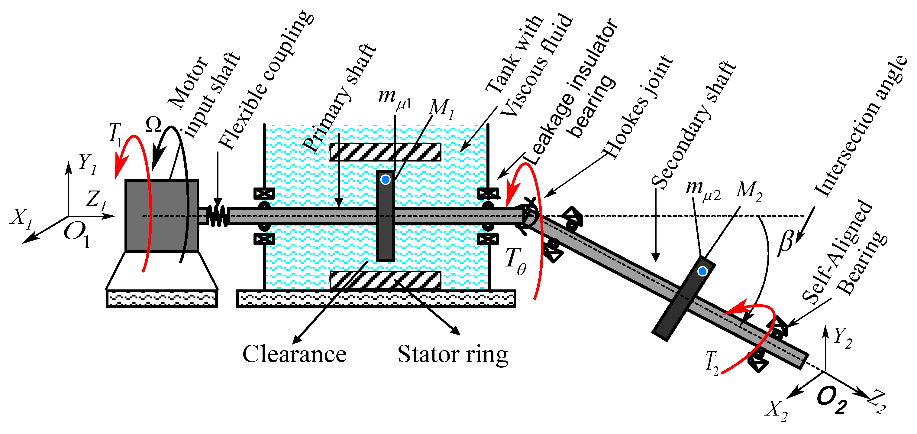
Figure 1. Sketch of the partially immersed Cardan shaft system in a viscous fluid.
Applsci 11 08089 g001
Figure 2. Deformed configuration of the shaft attached with discs 1 and 2, respectively.
Applsci 11 08089 g002
Figure 3. Schematic coordinate frame of (a) the whirling streamline of the driveshaft, (b) Lumped mass point.
Applsci 11 08089 g003
Figure 4. Model of the driveshaft–stator contact (a) Rub-impact diagram (b) Wet rub-impact configuration.
Applsci 11 08089 g004
Figure 5. Rotor system fluctuation (a) driveshaft disturbance function profile in the fluid medium at a variable joint angle β = 6 , 4 , 2 (b) centrifugal fluid forces perturbation.
Applsci 11 08089 g005
Figure 6. Motor torque fluctuation (a) torsional torque transmitted to the driveshaft (b) driveshaft speed profile at a maximum speed of 1500 rpm.
Applsci 11 08089 g006
Figure 7. Dynamic response of driveline rotors (a,b) displacement orbit of the input and output unbalanced shafts, (c) Fast Fourier Transform spectrum response, (d) transient time domain response.
Applsci 11 08089 g007
Figure 8. Driveshaft frequency domain of angular velocity during acceleration. (a) motor speed variation frequency (b) angular velocity vibration amplitude of the unbalanced driveshaft.
Applsci 11 08089 g008
Figure 9. Dynamic response of driveline rotors with driveshaft-to-stator rubbing (a,b) orbit of the input and output unbalanced shafts (c) Fast Fourier Transform spectrum response (d) transient deflection response of shafts.
Applsci 11 08089 g009
Figure 10. The 3-D driveshaft frequency spectrum of angular velocity during acceleration. (a) motor speed variation frequency (b) angular velocity vibration of the unbalanced and rubbing driveshaft.
Applsci 11 08089 g010
Figure 11. Frictional forces profile. (a) dry driveshaft–stator friction (b) wet driveshaft–stator rubbing effect.
Applsci 11 08089 g011
Figure 12. Dynamic response of driveline rotors with driveshaft-to-stator rubbing inside fluid (a), (b) orbit of the input and output shafts, (c) Fast Fourier Transform spectrum response (d) transient deflection response of shafts.
Applsci 11 08089 g012
Figure 13. The 3-D driveshaft frequency spectrum of angular velocity during acceleration inside fluid (a) Motor speed variation frequency (b) Angular velocity vibration of the unbalanced and rubbing driveshaft.
Applsci 11 08089 g013
Table 1. Rotor system R-K 4 parameters.
Shaft ParametersValue and UnitsShaft ParametersValue and Units
Length of the shaft (L)570 mmShaft stiffness K1X7.35 × 105 Nm−1
Shaft Diameter (D)10 mmShaft torsional stiffness K1T6.9 kNm−1/rad
Shaft torsional damping (C1T)90 Nms./radStator stiffness Ks8 × 106 Nm−1
Disc thickness (Ddisc)10 mmDiscsValue and Units
Disk moment of inertia (JD)0.1861 kg m2Mass (M)16.845 kg
Motor moment of inertia (JM)10.1861 kg m2Eccentricity mass (mu)0.25 g
Friction coefficient ( λ )0.2unbalance eccentricity (e)10 mm
Hooke’s joint angle ( β ) 7 ° Radial clearance (δ)2.35 × 10⁻⁵ m
Table 2. Viscous fluid properties. (Oil type GST Oil 32 (Chevron)).
ParametersValue
Oil 20 °C
ω 36.86 rad/s
Viscosity ( υ )4.2 × 10⁻⁶ m2 /s
Mass mfl43.82 kg
Euler constant ϒ 0.5772156
Publisher’s Note: MDPI stays neutral with regard to jurisdictional claims in published maps and institutional affiliations.