Article

Experimental Study on Micro-Grinding of Ceramics for Micro-Structuring

1
Department of Mechanical Engineering, Graduate School, Soongsil University, 369 Sangdo-ro, Dongjak-gu, Seoul 06978, Korea
2
School of Mechanical Engineering, Soongsil University, 369 Sangdo-ro, Dongjak-gu, Seoul 06978, Korea
*
Author to whom correspondence should be addressed.
Appl. Sci. 2021, 11(17), 8119; https://doi.org/10.3390/app11178119
Submission received: 30 June 2021 / Revised: 23 August 2021 / Accepted: 28 August 2021 / Published: 31 August 2021
(This article belongs to the Special Issue Additive Manufacturing for Composite Materials)

Abstract

:
In this study, micro-grinding was performed to investigate the machining characteristics of alumina and zirconia. The machining of ceramics remains highly challenging owing to their properties, such as high brittleness and wear resistance, which leads to a shorter tool life and high machining costs. Polycrystalline diamond (PCD) was selected as the tool material, as it is suitable for machining hard and brittle materials, and micro-electrical discharge machining (EDM) was used to fabricate PCD micro-tools. When using a resistor-capacitor generator circuit in micro-EDM, the discharging energy is related to the working capacitance, and by controlling the working capacitance, the different edge radii and the surface roughness of the tool can be easily achieved. The feed rate, depth of cut, and rotation speed were set as experimental parameters to investigate the grinding characteristics of the ceramics. During the experiment, the grinding force and roughness of the bottom surface were monitored, and the roughness of the machined surfaces was measured using a three-dimensional surface profiler. A working capacitance of 1000 pF was used to fabricate a tool with an edge radius of 3.5 µm. The lower radius of the tool edge resulted in a decrease of the cutting force by 50% at most and a surface roughness of 19 nm Ra.

1. Introduction

Ceramic materials have attracted attention as possible substitutes for metals for structural parts used in several industrial fields and multiple advanced industries due to promising characteristics, such as low density and high strength, as well chemical resistance [1,2,3,4,5]. However, the advantageous mechanical properties of ceramics can be a disadvantage in fine-shape processing [6,7]. Owing to the high hardness of ceramic materials, the tool wear increases during mechanical processing, which increases the cost of processing; because of the brittle nature of these materials, the machined surface is not smooth or breaks irregularly. These issues limit the application of ceramics, particularly in fields that use structures of tens to hundreds of microns.
Various types of unconventional machining methods have been attempted to overcome the challenges of ceramic processing. Laser machining involves melting and removing the material at the high temperature of the laser or modifying the surface of the material to reduce the cutting force and wear on the tool during machining. Gartner et al. used a picosecond laser to investigate the processing characteristics of aluminum oxide ceramics and proposed a model to predict the results of the machined surface using processing parameters, such as scanning speed and laser power [8]. In the grinding of oxidized zirconium ceramics using a diamond-coated tool, Kisaki et al. achieved a reduction of the fracture toughness of the material and the machining force and changed the surface condition during processing with laser [9].
Electrical discharge machining (EDM) is a method involving material melted by high-temperature heat generated by a spark and removed together with a melting explosion. In the case of a non-conductive material, a conductive substance, such as copper, can be applied to the surface of the material to form an assisting electrode, and the surface material can be melted and processed. Ferraris et al. studied the machinability of conductive ceramic composites based on alumina and zirconia using micro-EDM [10]. Banu et al. applied a copper-based assisting electrode on the surface of zirconia ceramics to produce a conductive layer to proceed with EDM, and analyzed the material removal rate and the hardness of the high layer for retesting [11].
The use of machining methods that use a heat source, such as laser machining and EDM, can result in the formation of micro-cracks on the surface of the material because of the high temperature. In addition, heat can modify the material around the machining area and change its physical properties. Furthermore, EDM can cause a decrease in machining shape accuracy owing to the tool wear.
Grinding with a diamond wheel can be considered when a uniform and smooth surface is needed in a material with high hardness. Rabiey et al. studied the machining conditions to achieve the ductile-brittle transition in zirconia grinding using hybrid bond diamond tools [12]. Dai et al. created a grinding simulation for silicon carbide machining and classified the damage that occurred on the surface [13]. The simulation results were compared with the experimental results obtained through actual grinding to machine a smooth ductile mode surface. However, such conventional grinding methods have several limitations, such as the long time required to improve the surface quality, the large size of the tool, and limitations regarding the shape of the material, because a large machining force acts when the tool and the material are in contact.
The grinding method using a micro-scale tool has been applied to processing of high-hardness materials in various industrial fields such as micro-optics, micro-dies and -molds, and micro-scale medical devices [14,15]. By adjusting the machining parameters, it is possible to achieve a crack-free surface in brittle materials using the ductile mode. Micro-tools can be relatively freely used to machine complex features of tens to hundreds of microns. However, the size effect of the micro-tool should be considered, as it can lead to tool breakage during machining. Subhash and Klecka utilized a single diamond particle to scratch the surface of alumina at a low depth [16]. Katahira et al. machined a SiC with a PCD grinding tool with a radius of 100 µm and investigated the machining characteristics and quality of the product [15]. As a result of the experiment, a high-quality ductile mode surface was obtained. Bian et al. used PCD and diamond-coated end grinding tools with a diameter of 1 mm for the ductile mode cutting of zirconia [17,18]. They studied the machining characteristics of zirconia considering the size effect of the tool, tool wear, and cutting surface.
However, there are few studies on micro-grinding of ceramics using micro-tools fabricated by electrical discharge. In the tool fabrication by EDM, applied voltage and working capacitance affect the edge radius and surface roughness of the tool. In this study, the effects of the electrical discharge parameters on tool geometries and grinding characteristics were investigated. A PCD micro-tool of 100–200 µm in diameter was fabricated by wire electrical discharge grinding (WEDG), a variant process of EDM [19], and the change in the surface roughness and the edge radius of the tool according to the working capacitance of an EDM circuit was measured. Additionally, the tool feed rate, depth of cut, and rotation speed were set as machining parameters, and the roughness of the machined surface and the machining force were measured. Furthermore, the wear of the tool and surface defects that occurred on the machined surface were analyzed.

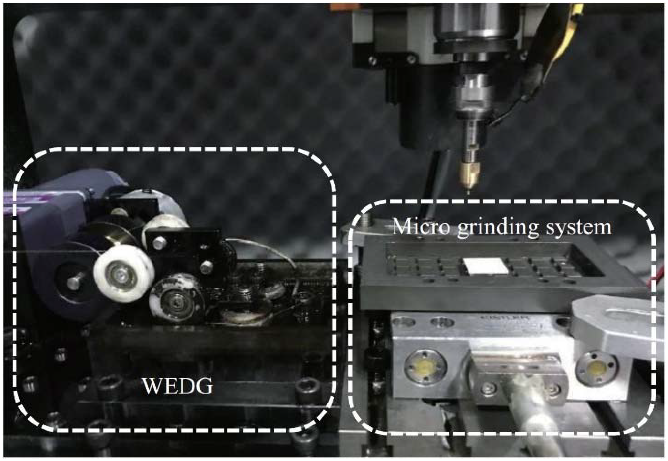
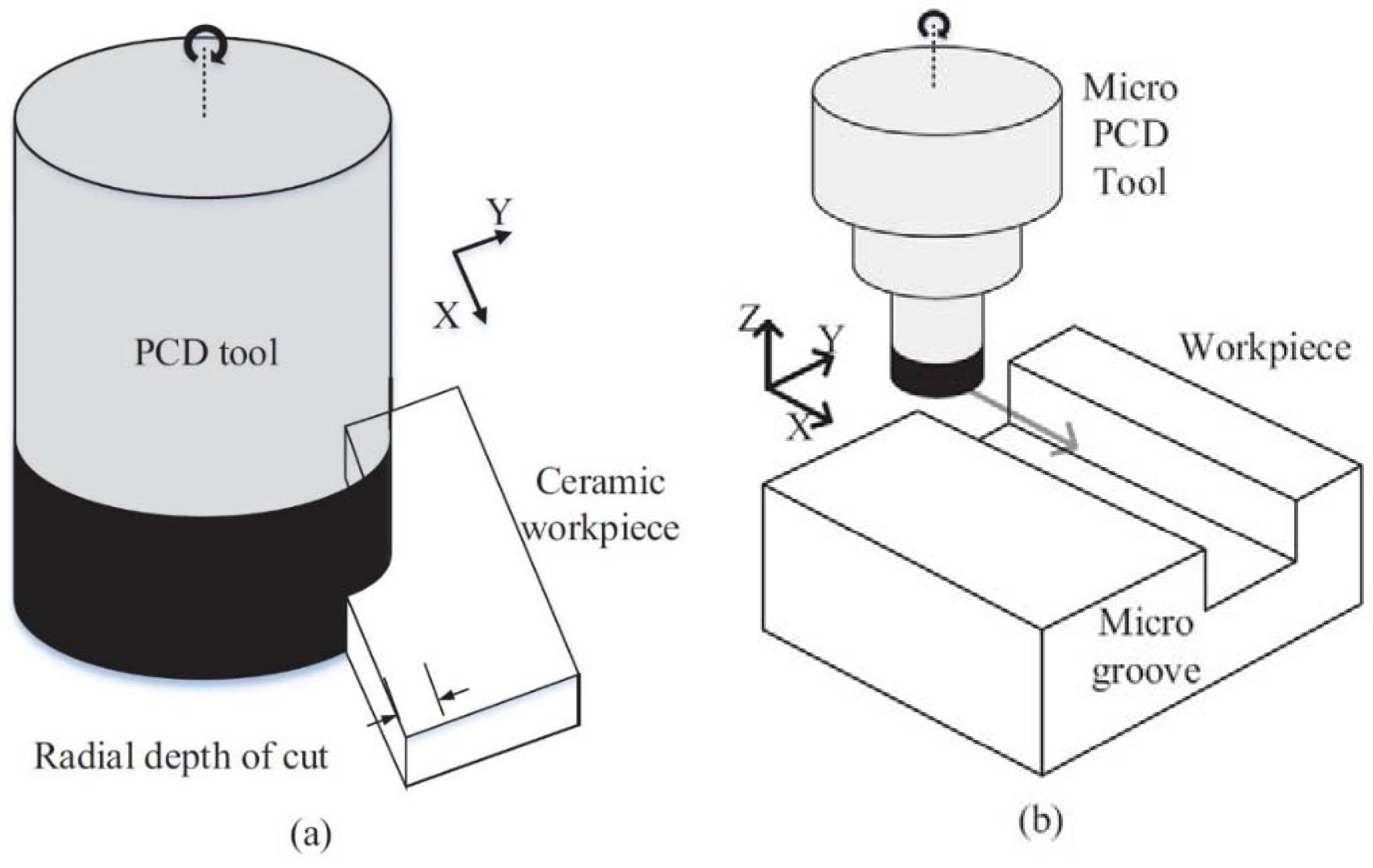
2. Experimental Setup

Table 1 shows the hardness of several hard materials, including ceramics. Cemented carbide (WC-Co), a common material used in commercial micro-tools, has a degree of hardness similar to that of alumina. Therefore, micro-tools made of cemented carbide suffer from severe tool wear while processing ceramic materials. In contrast, because the hardness of PCD is 3–5 times higher than that of alumina and zirconia, PCD is a suitable tool material for ceramic processing.
The fabrication of micron-sized PCD tools by grinding is a difficult and time-consuming process. Since polycrystalline diamond grains were sintered with cobalt binder, bulk PCD is electrically conductive. Therefore, electrical discharge has been widely used for manufacturing micron-sized PCD tools [22,23,24,25,26]. To manufacture the micro-tool, a 500-µm thick PCD layer is brazed to the end of a cemented carbide material with a diameter of 1000 µm. The grain size of PCD was 10 µm. In our experimental setup, micron-sized PCD tools were machined by WEDG [19]. WEDG is similar to wire EDM, but a metal wire electrode is fed along a wire guide in WEDG. In this study, a brass wire of 200 µm in a diameter was used as a wire electrode and EDM oil was used as a dielectric fluid to minimize the discharge gap. A resistor-capacitor (RC) generator circuit was used to generate the discharge. The resistance was 1 kΩ and the working capacitances of 1000 pF to 478 nF were used. The applied voltage was 100 V.
After WEDG, the tools were moved to a microgrinding system, where a ceramic workpiece was installed, as shown in Figure 1. As shown in Figure 2, two kinds of grinding processes were tested: side-grinding and groove-grinding. For the side-grinding, a circular tool with a diameter of 800 µm was used as shown in Figure 3a. For the groove-grinding, however, unstable machining may occur because of a grinding chip can be stuck between the tool and the workpiece during machining. To avoid this issue, a micro-tool with a D-shaped cross section and an inclined bottom surface was manufactured, as shown in Figure 3b. Table 2 and Table 3 show the machining parameters for the side-grinding and groove-grinding, respectively.
A high-speed spindle was equipped on the Z-axis of the precision stage, and the grinding force was measured using a dynamometer (9256C, Kistler Instrumente AG, Winterthur, Switzerland) on the X-Y-axes stage. The roughness of the tool and the machined surface were acquired using a laser confocal microscope (OLS5000, Olympus Corp., Tokyo, Japan). The magnification of an objective lens was 100×. A tilt removal and Gaussian filter were applied for the surface roughness measurement. Experiments and measurements were repeated three times for each parameter.

3. Results

3.1. Machining Characteristics of Zirconia
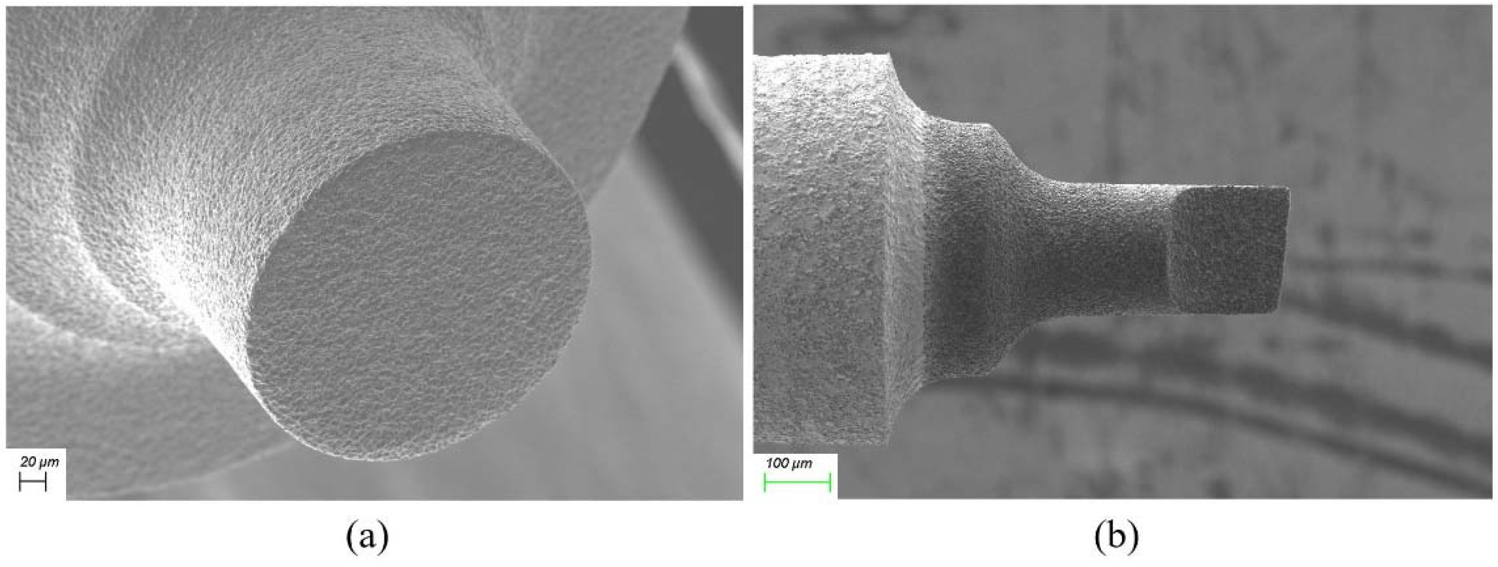
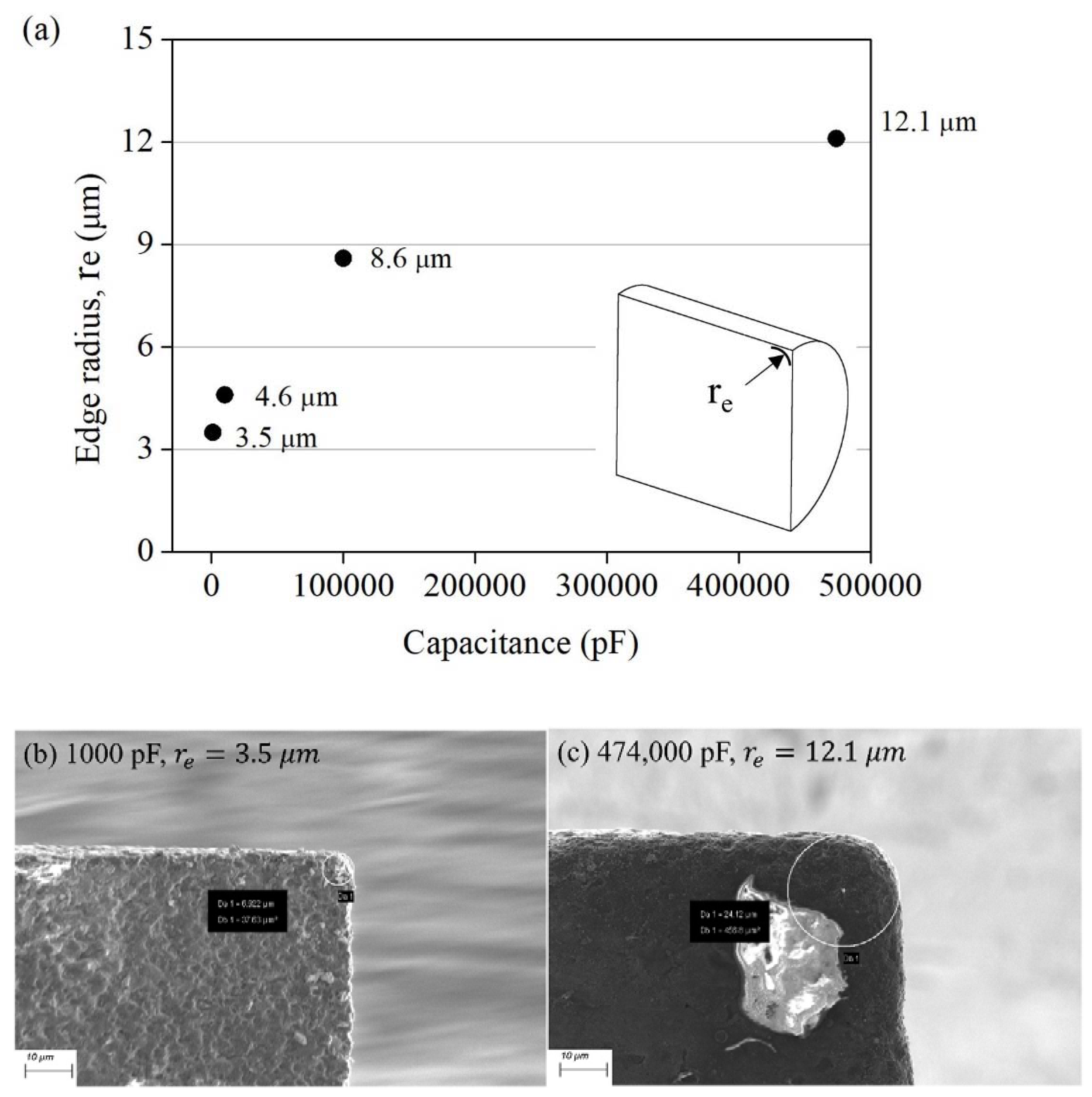
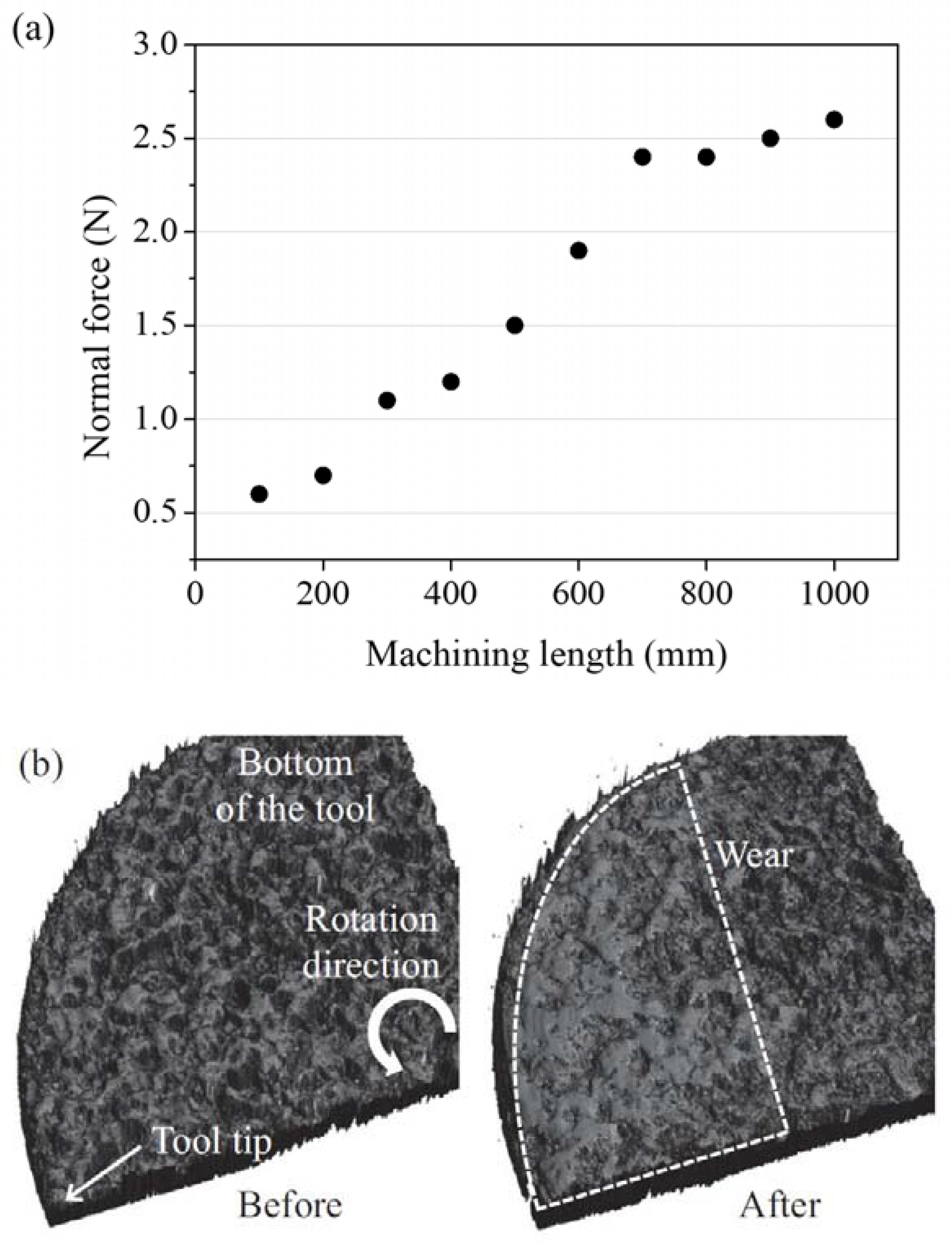
When a PCD tool is machined by EDM, the surface of the tool is covered with many craters generated by the EDM spark. As a result, a rough tool surface is obtained. During micro-grinding using an EDMed tool, the craters serve to remove material, which is similar to the action of abrasives of conventional grinding wheels. In conventional grinding, the larger the size of the abrasive of the tool, the higher the decrease in the grinding force. In EDM using an RC circuit, when the working capacitance increases, the crater size and tool surface roughness increase. Focusing on this point, an experiment was conducted to investigate the effect of the working capacitance on the grinding force. As shown in Figure 3a, a ceramic workpiece was ground using the side surface of the PCD tool, and the force components were measured. The PCD tools were fabricated with two different capacitances: 1000 pF and 474,000 pF. Figure 4 shows a graph of the force components according to the working capacitance used in tool fabrication. Using a tool machined at 474,000 pF, the normal force (y-direction) was reduced by 36%, compared to using a tool machined at 1000 pF. Since the radial depth was only 5 µm, the change in the tangential force was very small.
Next, the effect of the working capacitance on the normal force (z-direction, Fz) was investigated in the machining of micro-grooves, as shown in Figure 3b. In this experiment, tools with a diameter of 200 µm were fabricated with a working capacitance in the range of 1000 to 100,000 pF. Figure 5 shows the normal force at different feed rates when micro-grooves were machined using tools with working capacitances of 1000 and 100,000 pF. When a tool manufactured with a capacitance of 100,000 pF was used, the normal force was higher than that manufactured with a capacitance of 1000 pF; in particular, when the tool feed rate was 200 µm/s, the normal force was increased by up to 50%. When a large capacitance is used, as the size of the craters formed on the tool surface increases, the surface roughness of the tool also increases. The grinding force tends to decrease as the capacitance increases, similar to side-grinding. However, the experimental results indicated that the grinding force increased despite the use of a larger capacitance (100,000 pF). To analyze these contrasting tendencies, an experiment was conducted to investigate the change in the tool geometry according to the working capacitance used during tool fabrication. It is noted that the tool edge between the side and bottom of a tool is not involved during the side-grinding. Regarding the size effect on micro-grinding using a micro-tool, machining with the edge of the tool participating must be considered. To identify the influence of the tool during groove-grinding with a micro-tool, the edge radius of the tool was analyzed. In EDM, the current was concentrated in a sharp part such as an edge during machining [27], and resulted in the rounding of the edge. If the discharge energy is reduced using a condenser with a small capacitance, sharper edges can be obtained with a smaller energy. In this study, the micro-tool was manufactured with the capacitance of 1000, 10,000, 100,000, and 474,000 pF to confirm the change in the edge radius of the tool. Figure 6 shows the change in the edge radius (re) according to the working capacitance. A tool with an edge radius of 3.5 µm was fabricated using a capacitance of 1000 pF. Figure 6a,b show scanning electron microscopy (SEM) images of the edges of the machined tools with capacitances of 1000 and 474,000 pF, respectively. Considering the grinding force increment in Figure 5, it is possible to infer that the tool with a larger edge radius produced with a larger capacitance resulted in a higher minimum uncut chip thickness, enhancing the ploughing effect with smaller chip formation, and also resulting in a higher grinding force [28,29].
Using a micro-tool with a diameter of 200 µm, the grinding characteristics of zirconia were investigated with respect to the tool feed rate, depth of cut, and rotation speed. Figure 7 shows that as the feed rate increases, the grinding force increases, and the grinding marks are clearly evident in the photographs in Figure 8. Considering the increase in the roughness of the machined surface in Figure 7, it can be assumed that as the tool feeds, the cusp grows, leaving a clearer grinding mark. Figure 9 shows the 2D and 3D profiles of the surfaces.
Experiments were performed by changing the depth of cut to confirm the size effect depending on the edge radius. By using a tool with a capacitance of 10,000 pF, an edge radius of 9.2 µm was obtained. Figure 10 shows the force component in the feed direction (Fx) increased for depths of cut of 10 µm or higher. This means that the side surface of the tool participated in machining when the depth of the cut was larger than the edge radius.
From Figure 11a, the experimental results indicate that with a depth of cut of 10 µm or more, the surface roughness of the machined surface increased. As shown in Figure 11b, some defects were observed on the surface at 15 µm.
Figure 12 shows the decrease in the normal force according to the tool’s rotational speed. As the rotational speed increased, the unit material removal volume and the grinding force decreased. The roughness of the machined surface was reduced from 30 nm to 18 nm in Ra.
Figure 13 shows the spiral structure on the surface of zirconia machined by micro-grinding. The structure had 600 µm in width and 300 µm in height. The machining conditions used were the following: feed rate of 100 µm/s, depth of cut of 10 µm, and rotation speed of 30,000 rpm. Figure 14 shows the SEM images of the chips obtained during the grinding of zirconia. They consist of a lot of debris or particles of 1 µm or sub-micron size.

Tool Wear

To investigate the wear of the PCD tool, the change of the force and tool surface were monitored. The experiment was conducted at a tool feed rate of 100 µm/s, depth of cut of 3 µm, and rotation speed of 30,000 rpm. The smooth surface, which is considered to be tool wear, gradually spread from the tool tip. From Figure 15a, when compared with the initial stage of machining, the normal force was increased by four times or more. Figure 15b shows the surface profiles measured by comparing the changes in the bottom surfaces of the tool before and after grinding. The smooth surface spread from the tool tip after a length of 1000 mm, which was abrasion wear. Considering that the roughness of the tool tip area in Figure 16 decreased, the protruding part of the discharge surface wore out in height, leading to chip interference and reducing the chip evacuation during processing with a higher grinding force.

3.2. Machining Characteristics of Alumina

Figure 17 shows the change in normal force acting on the tool with a diameter of 100 µm while processing alumina, according to the feed rate. The normal force increased with the increase in the feed rate, and many surface defects occurred due to the brittle nature of alumina. The SEM images in Figure 18 show that, as the feed rate increased, grains were broken on the bottom of the groove, causing several defects; however, at a feed rate of 50 µm/s, the percentage of smooth surface increased.
Figure 19a shows the change in the grinding force according to the depth of the cut. It can be observed that as the depth of cut increased from 5 to 7 µm, the grinding force increased, and the ratio of the area of defects on the floor surface also increased. When compared with the experimental results presented in the previous section, it is possible to consider that a smooth surface may be produced from alumina by reducing the unit machining volume rate via the tool feed rate and depth of cut. Figure 19b shows the results of measuring the grinding force according to the rotation speed of the tool. At 20,000 rpm, with the largest machining volume rate per revolution, a large number of surface defects occurred. At the higher rotation speed of 30,000 rpm, the grinding force was reduced, resulting from the reduction of machining volume rate per revolution.
Figure 20 shows the SEM images and 3D profiles of several types of defects that appeared on the ground surface of alumina. In Figure 20a, defects appear in the cavities and are considered to be the original defects of the ceramic material. In addition, the surface of the material was separated from the chip near the processing marks, generating micro-pits. Owing to the brittle nature of ceramics, various forms of defects can occur on the work surface. In Figure 20b, an intergranular fracture was found, in which grains of several tens of microns were separated from the boundary [30].

4. Conclusions

In this study, grinding was performed using a micro-tool for high-hardness zirconia and alumina ceramics. Considering the size effect of micro-machining, the characteristics of the micro-grinding of ceramics were investigated by adjusting the working capacitance, tool feed rate, depth of cut, and rotation speed as parameters.
In the grinding with the side surface of the tool, the increase in the working capacitance during tool fabrication by EDM caused a decrease in the normal force. On the contrary, the normal force in the machining of micro-grooves increased continually as the working capacitance increased. To determine the cause of the contrasting tendency, the edge radius of the tools was investigated in terms of the size effect in macro-machining.
During the fabrication of the PCD tool, the edge radius was changed by adjusting the working capacitance. The larger the capacitance used to fabricate the tool, the larger the edge radius produced. Accordingly, the force acting on the tool manufactured with 1000 pF decreased by up to 50% compared to that of the tool with 100,000 pF.
Next, the micro-grinding characteristics of zirconia were investigated. When the tool feed rate was increased by 50–400 µm/s, the normal force increased in the range of 0.35–0.85 N, and a smooth surface with a surface roughness of at least 19 nm Ra was obtained at a feed rate of 50 µm/s. As the depth of cut became larger than the edge radius of the tool, the proportion of the force in the feed direction increased, resulting in a larger number of defects. After grinding 1000 mm in length, the wear on the tool face was examined by SEM observation considering grinding force, surface roughness, and evident abrasion wear.
Finally, micro-grinding of alumina was conducted and produced a partially smooth surface with some defects and failures. When increasing the feed rate in the range of 50–1000 µm/s, the normal force increased up to 1.2 N, and the area where the fractures occurred widened. When the depth of the cut increased from 5 to 7 µm, the area of the fractured surface increased. Based on the results of observation of the machined surfaces, the defects were classified according to their shape into raw material defects and intergranular fractures resulting from the breakage of grain boundaries.

Author Contributions

Conceptualization and methodology, B.H.K. and Y.N.; formal analysis, Y.N. and U.S.L.; writing—original draft preparation, Y.N.; writing—review, B.H.K.; supervision, B.H.K.; funding acquisition, B.H.K. All authors have read and agreed to the published version of the manuscript.

Funding

This work was supported by the Technology Innovation Program (20010984) funded by the Ministry of Trade, Industry & Energy (MOTIE), Korea.

Institutional Review Board Statement

Not applicable.

Informed Consent Statement

Not applicable.

Conflicts of Interest

The authors declare no conflict of interest.

References

  1. Júnior, M.G.; de Angelo Sanchez, L.E.; França, T.V.; Fortulan, C.A.; da Silva, R.H.L.; Foschini, C.R. Analysis of the tool nose radius influence in the machining of a green ceramic material. Int. J. Adv. Manuf. Technol. 2019, 105, 3117–3125. [Google Scholar] [CrossRef]
  2. Jia, D.; Li, C.; Zhang, Y.; Yang, M.; Zhang, X.; Li, R.; Ji, H. Experimental evaluation of surface topographies of NMQL grinding ZrO2 ceramics combining multiangle ultrasonic vibration. Int. J. Adv. Manuf. Technol. 2019, 100, 457–473. [Google Scholar] [CrossRef]
  3. Kwak, J.-S.; Kwak, T.-S. Review of Technology Trends for Ceramics Removal-Machining. J. Korean Soc. Precis. Eng. 2013, 30, 1227–1235. [Google Scholar] [CrossRef]
  4. Shackelford, J.F.; Doremus, R.H. Ceramic and Glass Materials; Springer: Boston, MA, USA, 2008. [Google Scholar] [CrossRef]
  5. Zhang, Z.Y.; Peng, H.M.; Yan, J.W. Micro-cutting characteristics of EDM fabricated high-precision polycrystalline diamond tools. Int. J. Mach. Tool Manuf. 2013, 65, 99–106. [Google Scholar] [CrossRef]
  6. Rao, R.R.; Mariappan, L.; Roopa, H.N. Fabrication of Micro-featured Shapes of Alumina Ceramics. Procedia Mater. Sci. 2014, 5, 2595–2604. [Google Scholar] [CrossRef] [Green Version]
  7. Romanus, H.; Ferraris, E.; Bouquet, J.; Reynaerts, D.; Lauwers, B. Micromilling of Sintered ZrO2 Ceramic via cBN and Diamond Coated Tools. Procedia CIRP 2014, 14, 371–376. [Google Scholar] [CrossRef]
  8. Gartner, E.; Polise, V.; Tagliaferri, F.; Palumbo, B. Laser Micro Machining of Alumina by a Picosecond Laser. J. Laser Micro/Neuroeng. 2018, 13, 76–84. [Google Scholar] [CrossRef]
  9. Kizaki, T.; Ito, Y.; Tanabe, S.; Kim, Y.; Sugita, N.; Mitsuishi, M. Laser-assisted Machining of Zirconia Ceramics using a Diamond Bur. Procedia CIRP 2016, 42, 497–502. [Google Scholar] [CrossRef]
  10. Ferraris, E.; Reynaerts, D.; Lauwers, B. Micro-EDM process investigation and comparison performance of Al3O2 and ZrO2 based ceramic composites. CIRP Ann. 2011, 60, 235–238. [Google Scholar] [CrossRef]
  11. Banu, A.; Ali, M.Y.; Abd Rahman, M. Micro-electro discharge machining of non-conductive zirconia ceramic: Investigation of MRR and recast layer hardness. Int. J. Adv. Manuf. Technol. 2014, 75, 257–267. [Google Scholar] [CrossRef]
  12. Rabiey, M.; Jochum, N.; Kuster, F. High performance grinding of zirconium oxide (ZrO2) using hybrid bond diamond tools. Cirp Ann.-Manuf. Technol. 2013, 62, 343–346. [Google Scholar] [CrossRef]
  13. Dai, J.; Su, H.; Zhou, W.; Yu, T.; Ding, W.; Zhang, Q.; Zheng, Y. Finite element implementation of the tension-shear coupled fracture criterion for numerical simulations of brittle-ductile transition in silicon carbide ceramic grinding. Int. J. Mech. Sci. 2018, 146–147, 211–220. [Google Scholar] [CrossRef]
  14. Ferraris, E.; Vleugels, J.; Guo, Y.; Bourell, D.; Kruth, J.P.; Lauwers, B. Shaping of engineering ceramics by electro, chemical and physical processes. CIRP Ann. 2016, 65, 761–784. [Google Scholar] [CrossRef]
  15. Katahira, K.; Takesue, S.; Komotori, J.; Yamazaki, K. Micromilling characteristics and electrochemically assisted reconditioning of polycrystalline diamond tool surfaces for ultra-precision machining of high-purity SiC. CIRP Ann.-Manuf. Technol. 2014, 63, 329–332. [Google Scholar] [CrossRef]
  16. Subhash, G.; Klecka, M. Ductile to Brittle Transition Depth During Single-Grit Scratching on Alumina Ceramics. J. Am. Ceram. Soc. 2007, 90, 3704–3707. [Google Scholar] [CrossRef]
  17. Bian, R.; Ferraris, E.; Ynag, Y.F.; Qian, J. Experimental Investigation on Ductile Mode Micro-Milling of ZrO2 Ceramics with Diamond-Coated End Mills. Micromachines 2018, 9, 127. [Google Scholar] [CrossRef] [Green Version]
  18. Bian, R.; He, N.; Ding, W.Z.; Liu, S.Q. A study on the tool wear of PCD micro end mills in duc-tile milling of ZrO2 ceramics. Int. J. Adv. Manuf. Technol. 2017, 92, 2197–2206. [Google Scholar] [CrossRef]
  19. Masuzawa, T.; Fujino, M.; Kobayashi, K.; Suzuki, T.; Kinoshita, N. Wire Electro-Discharge Grinding for Micro-Machining. Cirp Ann.-Manuf. Technol. 1985, 34, 431–434. [Google Scholar] [CrossRef]
  20. Nakamoto, K.; Katahira, K.; Ohmori, H.; Yamazaki, K.; Aoyama, T. A study on the quality of micro-machined surfaces on tungsten carbide generated by PCD micro end-milling. Cirp Ann.-Manuf. Technol. 2012, 61, 567–570. [Google Scholar] [CrossRef]
  21. Telle, R. Chapter 1—Properties of Ceramics. In Handbook of Ceramics Grinding and Polishing, 2nd ed.; Marinescu, I.D., Doi, T.K., Uhlmann, E., Eds.; William Andrew Publishing: Boston, MA, USA, 2015; pp. 1–49. [Google Scholar] [CrossRef]
  22. Cho, Y.H.; Seo, Y.S.; Moon, I.Y.; Kim, B.H.; Park, K. Facile fabrication of superhydrophobic poly(methyl methacrylate) substrates using ultrasonic imprinting. J. Micromech. Microeng. 2013, 23, 055019. [Google Scholar] [CrossRef]
  23. Hwang, J.; Cho, Y.H.; Park, M.S.; Kim, B.H. Microchannel Fabrication on Glass Materials for Microfluidic Devices. Int. J. Precis. Eng. Manuf. 2019, 20, 479–495. [Google Scholar] [CrossRef]
  24. Maeng, S.; Lee, P.A.; Kim, B.H.; Min, S. An Analytical Model for Grinding Force Prediction in Ultra-Precision Machining of WC with PCD Micro Grinding Tool. Int. J. Precis. Eng. Manuf.-Green Technol. 2020, 7, 1031–1045. [Google Scholar] [CrossRef]
  25. Morgan, C.J.; Vallance, R.R.; Marsh, E.R. Micro machining glass with polycrystalline diamond tools shaped by micro electro discharge machining. J. Micromech. Microeng. 2004, 14, 1687–1692. [Google Scholar] [CrossRef]
  26. Pratap, A.; Patra, K.; Dyakonov, A.A. A comprehensive review of micro-grinding: Emphasis on toolings, performance analysis, modeling techniques, and future research directions. Int. J. Adv. Manuf. Technol. 2019, 104, 63–102. [Google Scholar] [CrossRef]
  27. Li, X.; Wang, Y.; Liu, Y.; Zhao, F. Research on Shape Changes in Cylinder Electrodes Incident to Micro-EDM. Adv. Mater. Sci. Eng. 2019, 2019, 8087462. [Google Scholar] [CrossRef] [Green Version]
  28. Bissacco, G.; Hansen, H.N.; Slunsky, J. Modelling the cutting edge radius size effect for force prediction in micro milling. CIRP Ann. 2008, 57, 113–116. [Google Scholar] [CrossRef]
  29. Malekian, M.; Mostofa, M.G.; Park, S.S.; Jun, M.B.G. Modeling of minimum uncut chip thickness in micro machining of aluminum. J. Mater. Process. Technol. 2012, 212, 553–559. [Google Scholar] [CrossRef]
  30. Zhang, Y.-N.; Lin, B.; Liu, J.-J.; Song, X.-F.; Key, J.Y. An Experimental Study on Mechanical Modeling of Ceramics Based on Microstructure. Appl. Sci. 2015, 5, 1337–1349. [Google Scholar] [CrossRef] [Green Version]
Figure 1. Experimental setup.
Applsci 11 08119 g001
Figure 2. Schematic of (a) side-grinding and (b) groove-grinding.
Applsci 11 08119 g002
Figure 3. SEM images of PCD grinding tool: (a) cylindrical tool and (b) inclined D-shape tool.
Applsci 11 08119 g003
Figure 4. Force component comparison according to different working capacitances used in tool fabrication.
Applsci 11 08119 g004
Figure 5. Comparison of normal force (Fz) at different feed rates of tools fabricated using working capacitances of 1000 and 100,000 pF.
Applsci 11 08119 g005
Figure 6. (a) Effect of the working capacitance on the tool edge radius (re) and SEM images of the edge fabricated with capacitances of (b) 1000 pF and (c) 474,000 pF.
Applsci 11 08119 g006
Figure 7. Influence of the feed rate on the normal force (Fz) and roughness of the machined surfaces (tool diameter: 200 µm, depth of cut: 10 µm, rotation speed: 30,000 rpm).
Applsci 11 08119 g007
Figure 8. SEM images of the cutting marks on the grooves for different tool feed rates: (a) 50 µm/s, (b) 200 µm/s, and (c) 400 µm/s (tool diameter: 200 µm, depth of cut: 10 µm, rotation speed: 30,000 rpm).
Applsci 11 08119 g008
Figure 9. 2D and 3D surface profiles of the grooves for different tool feed rates: (a) 50 µm/s, (b) 200 µm/s, and (c) 400 µm/s.
Applsci 11 08119 g009
Figure 10. Effect of the depth of cut on the grinding force components.
Applsci 11 08119 g010
Figure 11. (a) Effect of the depth of cut on the roughness of machined surfaces. (b) SEM images of the surfaces.
Applsci 11 08119 g011
Figure 12. Normal force (Fz) and surface roughness obtained by varying the rotation speed of the tool.
Applsci 11 08119 g012
Figure 13. SEM image of the micro-spiral structure ground by a PCD tool.
Applsci 11 08119 g013
Figure 14. SEM image of chips during the grinding of zirconia.
Applsci 11 08119 g014
Figure 15. (a) Normal force (Fz) according to the machining length and (b) tool bottom surface profiles before and after 1000-mm grinding.
Applsci 11 08119 g015
Figure 16. Surface roughness change of the tool after grinding.
Applsci 11 08119 g016
Figure 17. Normal force at different tool feed rates (workpiece: alumina, tool diameter: 100 µm, axial depth of cut: 5 µm, tool rotation speed: 30,000 rpm).
Applsci 11 08119 g017
Figure 18. SEM images of the machined surfaces for different tool feed rates: (a) 50 µm/s and (b) 500 µm/s (depth of cut: 5 µm, tool rotation speed: 30,000 rpm).
Applsci 11 08119 g018
Figure 19. Normal force as a function of (a) depth of cut (feed rate: 50 µm/s, tool rotation speed: 30,000 rpm) and (b) rotation speed (feed rate: 100 µm/s, depth of cut: 3 µm).
Applsci 11 08119 g019
Figure 20. SEM images of defects on the machined surface of alumina: (a) defects caused by raw material pores and micro-pits separated with grinding chips and (b) intergranular fractures.
Applsci 11 08119 g020
Table 1. Hardness of PCD, alumina, WC-Co, and zirconia [18,20,21].
MaterialVickers Hardness
(100 g Load; kg/mm2)
PCD110–120
Alumina18–20
WC-Co17–18
Zirconia12
Table 2. Machining parameters for the side-grinding.
Tool materialPCD
Tool shapecircular tool of Ø 800 µm
Workpiece materialZirconia
Rotation speed (rpm)30,000
Feed rate (µm/s)250
Radial depth of cut (µm)5
Axial depth of cut (µm)100
Table 3. Machining parameters for the groove-grinding.
Tool materialPCD
Tool shapeD-shaped tool of Ø 200 µm
Workpiece materialZirconia
Rotation speed (rpm)10,000–30,000
Feed rate (µm/s)50–400
Axial depth of cut (µm)5–15
Publisher’s Note: MDPI stays neutral with regard to jurisdictional claims in published maps and institutional affiliations.

