Article

Dynamic Behavior Analysis of the Winding Rotor with Structural Coupling and Time-Frequency Varying Parameters: Simulation and Measurement

1
College of Mechanical Engineering, Donghua University, Shanghai 201620, China
2
Engineering Research Center of Advanced Textile Machinery, Ministry of Education, Shanghai 201620, China
*
Author to whom correspondence should be addressed.
Appl. Sci. 2021, 11(17), 8124; https://doi.org/10.3390/app11178124
Submission received: 1 August 2021 / Revised: 26 August 2021 / Accepted: 30 August 2021 / Published: 1 September 2021
(This article belongs to the Section Robotics and Automation)

Abstract

:

Featured Application

Flexible support is often used in high-speed flexible rotor systems, such as the textile winding rotor, to make the rotor pass smoothly through the critical speed points. The structural coupling, as well as time-varying and frequency-dependent parameters increase the complexity of the winding rotor dynamic behaviors and the difficulty of vibration control. This paper presents a method to reveal the dynamic behavior of the winding rotor through simulation analysis and non-contact test measurement, which have important potential applications in the design of flexible rotor structural parameters and process parameters.

Abstract

To satisfy the requirements of high speed, large capacity and constant winding, a textile winding rotor needs to work in a wide rotation speed range and frequently pass through critical speed points. Thus, the winding rotor adopts the flexible long shaft coupling structure and flexible support with rubber O-rings. This kind of rotor has a multi-coupling structure and frequency-dependent parameters characteristics, especially representative and universal in the dynamic analysis method of the high-speed rotor. In this paper, an approach was proposed to investigate the dynamic behavior of the winding rotor considering the flexible coupling and frequency-dependent supporting parameters. Firstly, a dynamic model of the winding rotor was established by using a Timoshenko beam element. Its dynamic behaviors were simulated by considering the time-varying rotation speed and the frequency-dependent parameters of flexible support. Secondly, a non-contact measuring device was developed for measuring the vibration displacement of the winding rotor in three different speed-up times. Finally, based on simulation and measurement data, how flexible support parameters and the speed-up time affect the winding rotor passing through the critical speed point of the rotor smoothly is revealed. The methods and findings reported here can be used for theoretical and experimental vibration analysis of other types of high-speed flexible rotors.

1. Introduction

Rotary machinery is widely used in many industrial fields such as machine tool spindles [1,2], aero-engines [3,4,5], turbopumps [6,7] and textile machines [8,9]. The core component of rotary machinery is a rotor system composed of a shaft, bearings, housings and other components. With technology advances, the rotary machinery including aero-engine rotors, textile winding rotors, etc., tend to high speed and large capacity. Correspondingly, the rotor’s rotational speed is becoming higher and higher, usually exceeding its second-order or even third-order critical speed. Accurately obtaining the critical speed points and unbalanced response characteristics of the rotor system is a necessary requirement for the reasonable design of rotor structural parameters and process parameters, thereby ensuring that the rotor can smoothly pass through the critical speed point and work stably in a wide operating speed range. This is one of the key aspects of modern rotor dynamics application research.
As early as 1965, Lund [10] first proposed that the rotational speed of the rotor system can be improved by using flexible support. Powell et al. [11] investigated the influence of rubber properties on the ability of rubber O-rings to suppress the self-excited whirl of rotors supported in resiliency mounted air bearings. In order to understand the performance of the rubber ring, Kazimierski and Jarzecki [12] studied its dynamic characteristics through theoretical and experimental methods, and the results show that an external pressure gas bearing system that was elastically supported by rubber O-rings can increase the stability threshold of the rotor system. Some scholars performed research on the flexible support structure of the rotor and its dynamic characteristics and vibration control.
The supporting stiffness and damping of the rubber O-ring show strong frequency-dependent characteristics since it is subjected to a high-frequency external load [13]. Currently, the experimental method is often used to identify the dynamic supporting parameters of the rubber O-ring [14].
To satisfy the needs of production, a typical textile winding rotor adopts a large length-to-diameter ratio cantilever structure with flexible support. It increases the difficulty of stable rotation in a wide working speed range where the winding rotor frequently passes through critical speed points. Meanwhile, high requirements are proposed to further theoretical and experimental research on vibration control.
Thus far, few researchers have studied winding rotor systems [8,9]. Subsequently, Wang et al. [14] considered the coupling characteristics of the winding rotor to establish its dynamic model and did a preliminary study on the winding rotor. The dynamic characteristics of the rotor system with complex coupling structure and frequency-dependent parameters should be further explored by simulation and test measurement.
In earlier studies of the rotor-bearing system, the transfer matrix method was used and bearings were simplified as rigid connection or linear spring-damper elements [15,16,17]. With the in-depth study of rotor dynamics, the factors that need to be considered for system modeling are increasing. It is difficult and even infeasible to use the transfer matrix method to deal with the coupling structure. Therefore, the transfer matrix method was gradually replaced by the finite element method.
Nelson et al. [15,18,19] constantly improved the rotor model, considering the rotor’s inertia moment, gyroscope effect, viscoelasticity of the rubber ring, etc., to study the dynamic characteristics of the rotor system by using the finite element method. Kalita [16] investigated the stability of the rotor-bearing system considering internal damping through the finite element method, and showed the relationship between the critical speed and the rotational speed of the rotor system through the Campbell diagram. Along with the ongoing research, as is known, the rotor-bearing system needs to regard the rotor as a complete system that includes the rotor shaft, bearings, support frame, etc. Dutt [17] established the finite element model of the rotor-bearing system, and studied the influence of the supporting stiffness and damping coefficients of the rubber O-ring on the stability of the system. Kang [20] built a rotor-bearing system model using the finite element method, and investigated the effect of different types of support on the stability of the system. Some scholars [21,22,23] studied the dynamics of the rotor system based upon different views of the modeling method.
The transient response of the bearing-rotor system during variable speed is one of the main research problems. Lee et al. [24] studied the transient vibration of asymmetric rotor systems during acceleration based on the finite element model and Newmark’s method. Lee et al. [25] proposed a transient response analysis technique of the rotor system, and used the generalized finite element modeling method of a rotor-bearing system. Kim et al. [26] performed damage detection from non-stationary mechanical vibration signals collected during acceleration and deceleration.
In addition to theoretical modeling, experimental testing is another important method to study the dynamic characteristics of the rotor system. It is difficult to obtain dynamic data of the rotor directly with contact measurement, because the rotor rotates at a high speed. Non-contact measurement technology does not interfere with the rotor rotation, and the sensor is easy to arrange. It is the first choice method for mechanical vibration measurement of the rotor system. Yang et al. [27] measured the actual axial clearance of the scroll air compressor under a working condition by using an eddy current displacement sensor, and the results show that the eddy current sensor has high sensitivity and preferable static and dynamic performances. Mirzaei et al. [28] developed a novel eddy current speed sensor to measure the rotation speed of conductive objects. However, the eddy current displacement sensor has high requirements for the tested object, such as a metal conductor. Unfortunately, there are some paper tubes around the winding rotor, which hinder the application of the eddy current sensor in the winding rotor. Although these methods are not applied to measure the vibration of the winding rotor, these references could throw light upon the thoughts of vibration displacement amplitude measurement of the winding rotor.
This paper aimed to investigate the dynamic characteristics of the winding rotor during its speeding up. Construction features of the winding rotor were analyzed in depth and the corresponding finite element model was established through a Timoshenko beam element and flexible support, considering the frequency-dependent supporting parameters of the rubber O-ring and the time-varying rotational speed. The dynamic equations considering the coupling effect between different nodes were derived by Newton’s second law, and the dynamic responses were simulated under the different supporting stiffness and damping coefficients of the rubber O-rings, as well as the speed-up time by means of Newmark time integration. The non-contact measurement device was then developed, the mechanical vibration of the winding rotor was carried out under different speed-up times. The test results show that the test curves are in good agreement with the simulation curves. The method and the main findings presented in this study can be used for mechanical vibration analysis of other types of high-speed flexible rotors.

2. Materials and Methods

The winding rotor structure, numerical modeling, simulation and experimental methods used for the flexible rotor-dynamics study and analysis are described in this chapter.

2.1. Description of Winding Rotor

The winding rotor is the key component of a winder for filament, its main structure is shown in Figure 1. To illustrate its structure more clearly, the reduction ratio of the winding rotor in the radial direction is smaller than that in the length direction.
To facilitate doffing the filament packages from the winding rotor, the winding rotor is designed as a cantilever beam structure. The supporting arm is fixed on a frame. Three sets of flexible supports with rubber O-rings are installed between the supporting arm and the shaft. The flexible support includes rubber O-rings, bushing and bearings, as shown in Figure 1b. The shaft is driven by a motor, and the interference fit between the shaft and the sleeve is used to maintain synchronous rotation. The paper tubes are rigidly connected with the sleeve through the tightening device to realize synchronous rotation, and the filament bundle is wound on the paper tubes. Usually, there are 12 packages on the winding rotor, and each package weighs about 10–15 kg in full volume.
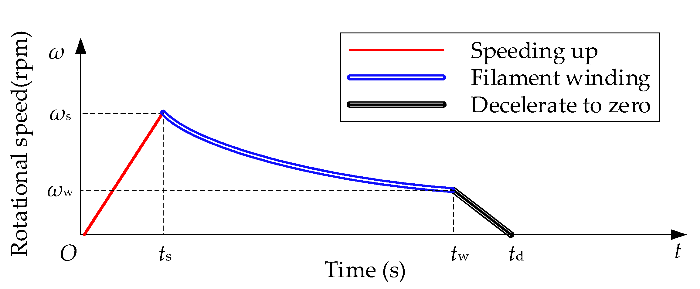
To ensure constant linear speed winding, the winding rotor starts to rotate and its speed increases quickly from 0 to ω s = 7730   rpm , and the filament bundle begins to be wound on the paper tubes. As the filament package diameter increases, the rotor speed nonlinearly reduces from the highest ω s to the lowest ω w , then the rotational speed gradually decreases to zero, and a single cycle of the winding task is usually accomplished in 1–3 h according to different types of filaments, as shown in Figure 2.
In Figure 2, t s is the end time during speeding up, t w is the end time during winding and t d is the end time during deceleration.
Due to its cantilever beam structure with a large aspect ratio and multi-coupling components with flexible support, the first-order critical speed point of the winding rotor is low. Within the maximum working speed of 7730 rpm, there are two critical speed points of the winding rotor. So, frequently passing through the critical speed points is the normal working state of the winding rotor.
To pass steadily through the critical speed points, the transmission with flexible support should be adopted according to the literature researches [14].
Due to the presence of rubber O-rings, changes in the speed of the winding rotor may change the frequency-dependent characteristics of the supporting stiffness and damping parameters of the flexible support. Therefore, the winding rotor has characteristics of time-varying rotational speed and frequency-dependent supporting parameters, as well as structural coupling, which makes the dynamic behavior of the winding rotor extremely complicated.

2.2. Theory and Modeling

According to the modeling principle and structural characteristics of the rotor-bearing system, a system analysis model of the winding rotor was established based on two assumptions. The first assumption was that the connection of each component is an ideal constraint, and the second assumption was that the bearing and the rubber O-ring are equivalent to a point mass.
The finite element model of the winding rotor was established by a cylindrical shaft beam element. In order to overcome the excessive number of nodes and elements in the analysis process of the winding rotor, equivalent simplifications of the winding rotor structure were carried out to decrease in calculation time. The following principles should be followed when simplifying: (1) since this paper did not focus on stress concentration, the structural chamfers that had little effect on the dynamic characteristics of the winding rotor are removed; (2) the contact properties of bearings and rubber O-rings were represented by equivalent spring-damping elements.
The geometric and shaft beam are homogeneous, the parts are made up of structural steel or rubber. The length of the element was divided according to the structure feathers and coupling relationships of the winding rotor, and the finite element model was established, as shown in Figure 3. Contact properties of each contact point were connected by the spring-damper element. There were three types of the contact coupling in the winding rotor: (1) the nodes of the contact coupling of the rubber O-rings were 2–11, 4–14, 6–18 and 8–19; (2) the nodes of the contact coupling of the bearings were 11–23, 14–28, 17–31 and 20–34; (3) the nodes of the interference contact coupling were 36–46 and 37–47.

2.2.1. Finite Element Theory of Rotor

Because the winding rotor is the cantilever beam structure, the motion and deformation mainly come from the radial direction during the high-speed rotating of the winding rotor. Therefore, this paper did not consider the deformation and rotation in the Z-axis (length) direction.
The cylindrical shaft beam element is shown in Figure 4, P and Q are two nodes of the beam element, and the local element spatial coordinates o - x y z   are established with the node P , z is tangent along the axis direction of the element, x and y are defined in the transverse direction of the element. l is the length of beam element and s is the distance between node P and arbitrary point on the centerline.
According to the structural features and the working characteristics of the winding rotor, axial motion and torsion were neglected, the translation of the cross-section centerline was given by the two distances ( u , v ), and rotation was given by the two angles ( θ x ,   θ y ) due to bending and shear deformation.
The generalized coordinates of the beam element can be expressed as following.
e = { u P x   v P y   θ P x   θ P y   u Q x   v Q y   θ Q x   θ Q y } T
where u P x and u Q x are the translation of the two nodes P and Q along the x -axis direction, respectively; v P x and v Q x are the translation of the two nodes P and Q along the y -axis direction, respectively; θ P x and θ Q x are the angular deformations rotating around the x axis; and θ P y and θ Q y are the angular deformations rotating around the y axis.
The generalized displacement of arbitrary points on the centerline is a position and time-dependent function, and the displacement can be expressed by displacement interpolation functions. For the shaft beam element, linear-displacement interpolation functions Ψ r and angular-displacement interpolation functions Φ r can be written as [29]
Ψ r = { Ψ 1 ( s ) Ψ 2 ( s ) Ψ 3 ( s ) Ψ 4 ( s ) } = { 1 1 + χ ( 2 a 3 3 a 2 + 1 + χ ( 1 + a ) ) l 1 + χ ( a 3 2 a 2 + a + 1 2 χ a ( 1 + a ) ) 1 1 + χ ( 2 a 3 + 3 a 2 + χ a ) l 1 + χ ( a 3 a 2 + 1 2 χ a 2 1 2 χ a ) } T
Φ r = { Φ 1 ( s ) Φ 2 ( s ) Φ 3 ( s ) Φ 4 ( s ) } = { 1 ( 1 + χ ) l ( 6 a ( a 1 ) ) 1 1 + χ ( 3 a 2 4 a + 1 + χ ( 1 a ) ) 1 ( 1 + χ ) l ( 6 a ( a 1 ) ) l 1 + χ ( 3 a 2 2 a + χ a ) } T
where a = s / l ; χ is the transverse shear effect and χ = 12 E I / K A b G l 2 ; E is the elastic modulus of beam element; I is the second moment of area and I = π ( D 4 d 4 ) / 64 ,   D and d are the outer diameter and inner diameter of the beam element; A b is the cross-section area of beam element; K is the transverse shear form factor; and G is the shear modulus.
The generalized displacement of a typical point internal to the beam element is approximated by the relation [15]
{ u x ( s , t ) v y ( s , t ) θ x ( s , t ) θ y ( s , t ) } = { Ψ 1 0 0 Ψ 2 Ψ 3 0 0 Ψ 4 0 Ψ 1 Ψ 2 0 0 Ψ 3 Ψ 4 0 0 Φ 1 Φ 2 0 0 Φ 3 Φ 4 0 Φ 1 0 0 Φ 2 Φ 3 0 0 Φ 4 } T e ( t )
Based on the Lagrange’s equation, the dynamic equations of the cylindrical shaft beam elements can be expressed as
M e c e ¨ ω G e c e ˙ + K e c e = F e c
where M e c is the mass matrix; G e c and K e c are the equivalent gyroscopic matrix and stiffness matrix of the beam element, respectively; and e , e ˙ and e ¨ , are the generalized arrays of displacement, velocity and acceleration of the beam element, respectively. F e c is the generalized force array of the beam element.
The mass matrix M e c of the beam element include the translational mass matrix { M e c } t r a n s and the rotatory mass matrix { M e c } r o t a , respectively, and they can be written as [15,29]
{ M e c } t r a n s = { M e t } 0 + χ { M e t } 1 + χ 2 { M e t } 2 { M e c } r o t a = { M e r } 0 + χ { M e r } 1 + χ 2 { M e r } 2
where { M e t } i and { M e r } i are given by the literature [15], i = 0 ,   1 ,   2 .
The gyroscopic matrix G e c and stiffness matrix K e c of the beam element can be written as [15,29]
G e c = { G e } 0 + χ { G e } 1 + χ 2 { G e } 2 K e c = { K e } 0 + χ { K e } 1
where { G e } i and { K e } i are given by the literature [15], i = 0 ,   1 ,   2 .

2.2.2. Coupling Model

In order to illustrate the coupling relationship of between node i and node j , a two-degrees-of-freedom spring-mass-damping system is used, and the draw free-body diagrams of the system as shown in Figure 5.
The coordinates describing the positions of the masses, x i ( t ) and x j ( t ) , are measured from their respective static equilibrium positions. F i ( t ) and F j ( t ) denote the forces acting on the node masses m i and m j , respectively. The equations of motion of the masses m i and m j can be derived and written as
[ m i 0 0 m j ] { x ¨ i x ¨ j } + [ c i + c s c s c s c s + c j ] { x ˙ i x ˙ j } + [ k i + k s k s k s k s + k j ] { x i x j } = { F i ( t ) F j ( t ) }
where k s and c s are the equivalent supporting stiffness and damping between two coupling nodes. k i and c i are the stiffness and damping of node i , and k j and c j are the stiffness and damping of node j .
(1)
Rubber O-Ring
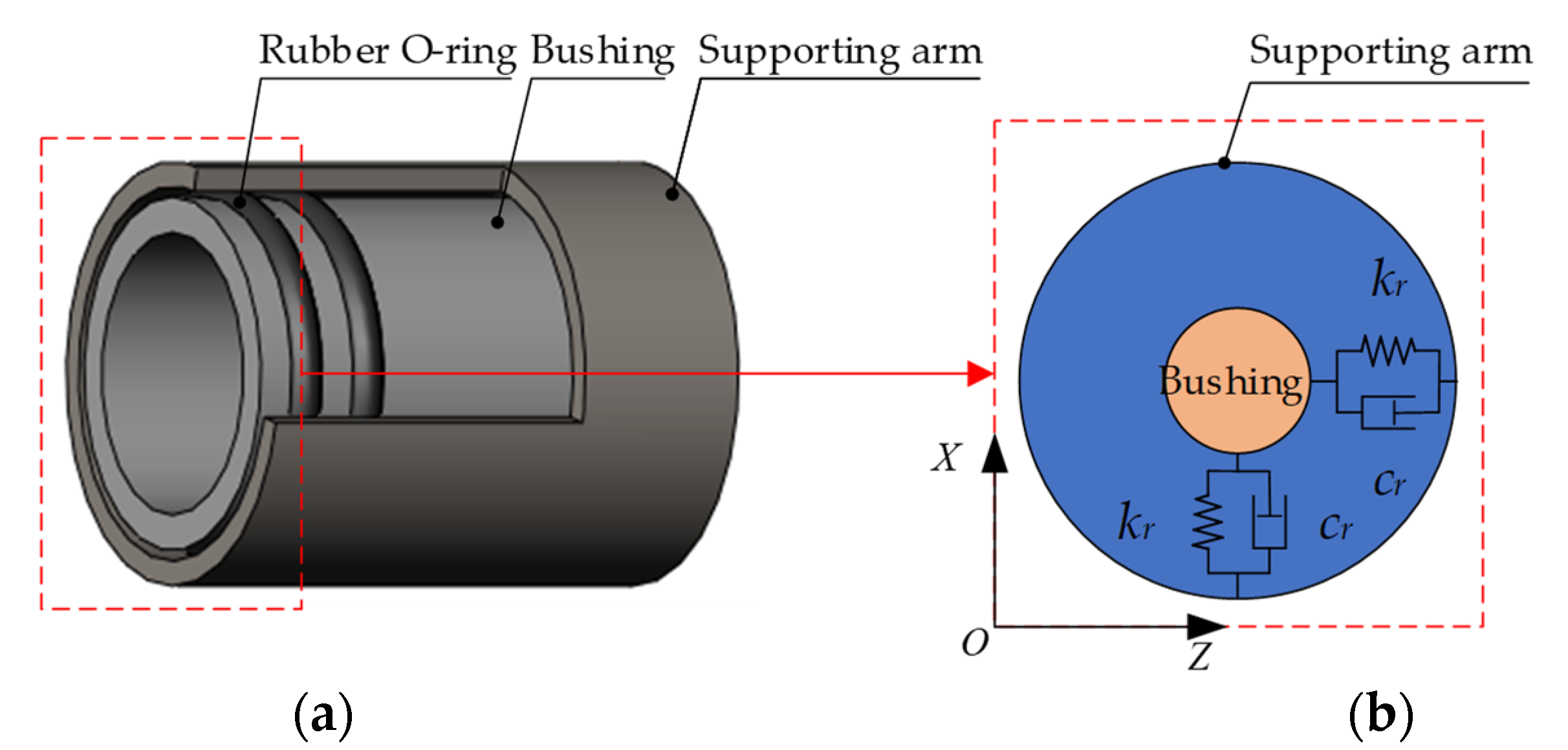
With the development of the textile industry, the winding speed is getting higher and higher, which leads to the rotational speed of the winding rotor to exceed the second- or third-order critical speed. To avoid heavy vibration when the winding rotor passes through the critical speed points, the structure of flexible support is adopted. The flexible coupling support with rubber O-rings is shown in Figure 6a.
The rubber O-ring is equivalent to a spring-damping element. In practice, the radial compression of the rubber O-ring installed in the winding rotor is less than 0.1 mm, and it is much smaller than the cross-sectional diameter of the rubber O-ring by 3.5–4 mm. Therefore, the supporting stiffness and damping of the rubber O-ring can be approximated as the linear elastic range, hence the spring-damping element may be further equivalent to the linear spring-damping element of the single-degree-of-freedom system in the X direction, as shown in Figure 6b.
The rubber O-ring is installed between the grooved bush and the supporting arm. The groove width is often larger than the cross-sectional diameter of the rubber O-ring. In addition, the groove is filled with grease. Therefore, a single rubber ring can only bear radial load, and multiple rubber rings installed in parallel produce a certain bending effect through their radial stiffness. Naturally, the rubber O-ring acts as a supporting element and does not limit the rotation.
When node i and node j are coupled through rubber O-rings, it is assumed that the rubber O-rings only restrict the displacement, but not the rotation. Therefore, stiffness and damping coupled nodes can be expressed as
K rubber = [ I 2 0 0 0 ] 4 × 4 k r i j C rubber = [ I 2 0 0 0 ] 4 × 4 c r i j
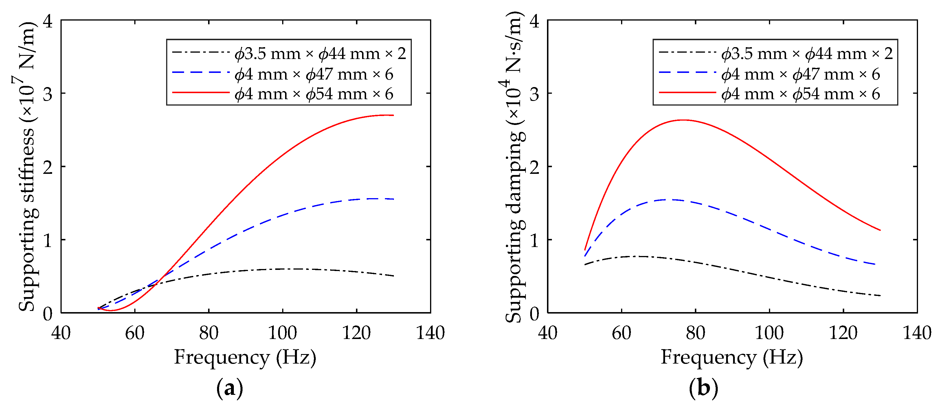
where I 2 is an identity matrix of order 2. k r and c r are the equivalent stiffness and damping coefficients of the rubber O-rings, respectively. The coefficients of the equivalent stiffness and damping coefficients of the rubber O-ring can be obtained through the forced non-resonance method [14], and the frequency-supporting stiffness curve and the frequency-supporting damping curve are presented in Figure 7.
Three types of rubber O-rings are used in the winding rotor shown in Figure 1, and they are always used in groups of 2, 4 and 6 rubber O-rings. With the increase of cross-sectional diameter ( Φ 3.5, Φ 4), outer ring diameter ( Φ 44, Φ 47, Φ 54) and number (2, 6) of rubber O-rings, the supporting stiffness and damping coefficients increase correspondingly, and show obvious frequency-dependent characteristics.
If node i and node j are coupled through the rubber O-rings, based on the theory of the two-degree-of-freedom spring-mass-damping system [30], the global coupling matrices of the stiffness and the damping of the winding rotor can be written as
K Rubber = [ 0 0 ( K rubber ) i i ( K rubber ) i j 0 ( K rubber ) j i ( K rubber ) j j 0 0 ] 208 × 208 C Rubber = [ 0 0 ( C rubber ) i i ( C rubber ) i j 0 ( C rubber ) j i ( C rubber ) j j 0 0 ] 208 × 208
(2)
Rolling Bearing
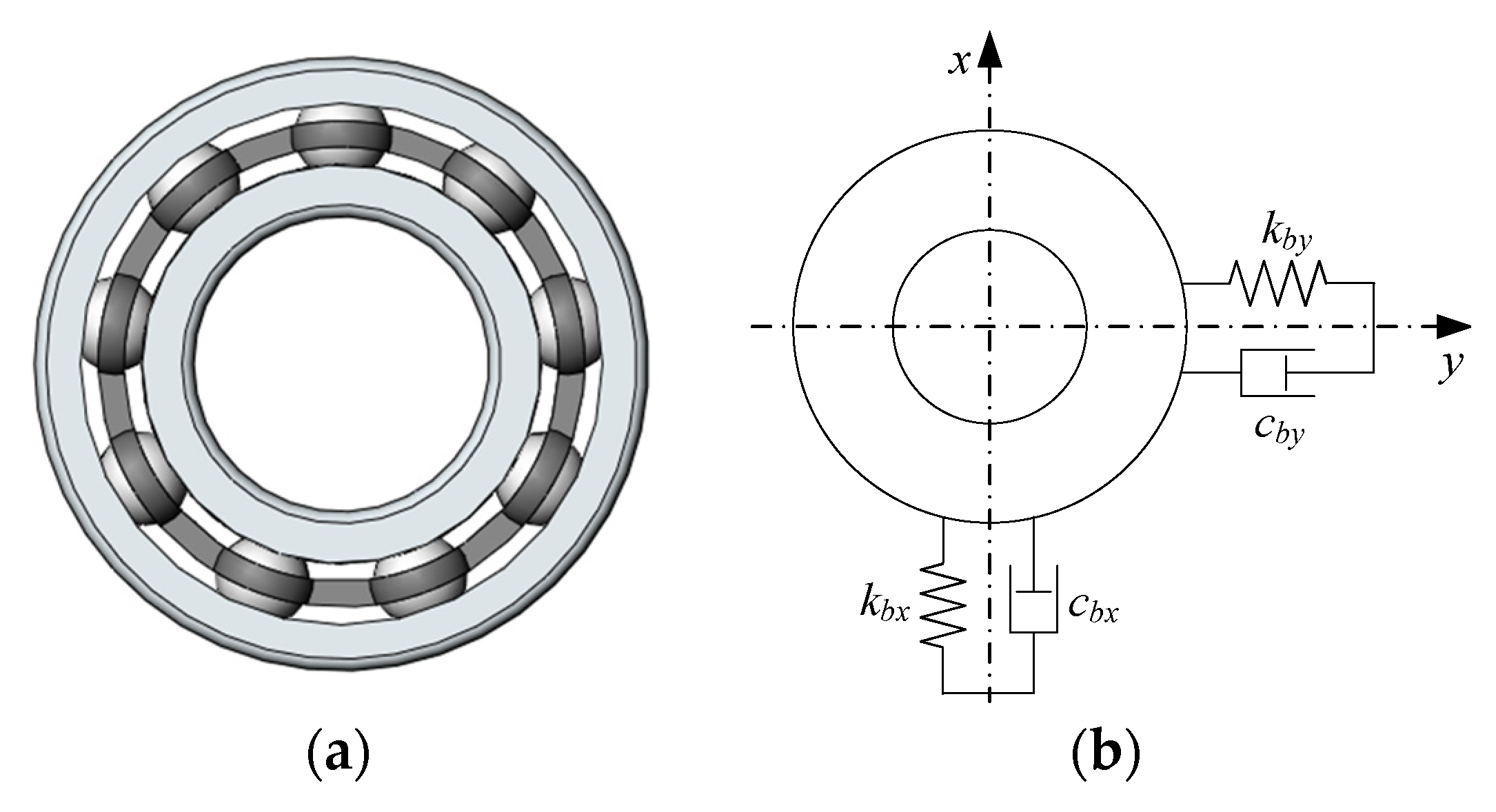
The rolling bearing is a rotating part which is affixed to the rotating shaft and the bushing, as shown in Figure 8a. Its main function is to transmit rotation and support the shaft. Usually, to simplify computing, the bearing is equivalent to the spring-damping unit shown in Figure 8b. The damping coefficient of multiple rubber rings installed in parallel is far higher than the bearing’s. Therefore, this paper ignores the impact of bearing damping on the winding rotor when building the model ( c b x = c b z = 0 ), and with the assumption that the bearing stiffness is symmetrical ( k b x = k b y ), the equivalent bearing stiffness coefficient is k s = 6 × 10 7   N / m [31]. The global coupling stiffness matrix of the rolling bearing is similar with the rubber O-ring.
When the bearing is coupled with other parts, just the coupling effect of equivalent radial stiffness is considered an equivalent axial stiffness of the bearing and is ignored in this paper. The bearing also restricts the displacement, but not including the rotation. Therefore, the global coupling matrix form of equivalent stiffness and damping of the bearing is the same as the rubber O-ring.
(3)
Interference Connection
When the shaft is coupled with the sleeve, it is assumed that nodes i and j are coupled by the interference connection, which restricts the total of eight coordinates of two coupled nodes just in their stiffness. Because the shaft is fixed rigidly to the sleeve, there is no relative motion between them during rotation, hence the damping between them is not considered. The equivalent stiffness of the interference connection was obtained by the static analysis, and the coefficient is k s = 1.036 × 10 8   N / m . The global coupling stiffness matrix of the interference connection is similar to that of the rubber O-ring.

2.2.3. Dynamic Equations of Winding Rotor

The motion differential equations of the winding rotor can be derived by Newton’s second law [32], and the dynamic equations can be written as
M s { u ¨ s } + ( C s Ω G s ) { u ˙ s } + K s { u s } = { F s } + { F g }
where M s = diag   ( M s 1 , , M s 6 ) , M s 1 , , and M s 6 are the mass matrices of the supporting arm, flexible support , and , the shaft and the sleeve, respectively. The superscript s 1 , s 2 , , and s 6 represent the six components, respectively. Ω = diag ( { 0 , 0 , , 0 } 1 × 84 , { ω , ω , , ω } 1 × 124 ) is the rotating angular speed matrix of the winding rotor. K s , C s and G s are the matrices of stiffness, damping and gyroscopic moment.   u s , u ˙ s , and u ¨ s are the generalized arrays of displacement, speed and acceleration, respectively.   F s is the generalized array of force and F g is the gravity vector.

2.3. Numerical Solution Algorithm

In this paper, the Newmark time integration method is used to solve the dynamic equations, and the corresponding iterative equations are given by [33]
{ u t + Δ t = u t + Δ t u ˙ t + ( ( 1 2 η ) u ¨ t + 2 η u ¨ t + Δ t ) Δ t 2 u ˙ t + Δ t = u ˙ t + Δ t ( ( 1 γ ) u ¨ t + γ u ¨ t + Δ t )
where γ and η are the parameters determined according to the requirements of integration accuracy and stability. Usually, γ = 0.5 and η = 0.25 .
The dynamic behavior of the winding rotor was investigated during speeding up, of which the angular speed increases linearly, namely, a constant of the angular acceleration. In each iterative process, the variation of the angular speed is related to the time, as shown in Figure 9. The iterative formula is expressed as
ω i + 1 = ω i + ω s t s ( t i + 1 t i )

2.4. Measurement Device

In this paper, an optical displacement digital micrometer sensor (Model: Keyence LS-9000) was used to measure the radial vibration of the winding rotor, which accurately obtains the vibration displacement amplitude of the object based on the principle of laser beam shielding. In addition, LMS SCADAS Mobile was used for data acquisition. These two instruments’ parameters are listed in Table 1.
The scheme of vibration measurement is shown in Figure 10a, and the corresponding measuring device is shown in Figure 10b. To reduce the impact of ground vibration on the tests, four air mounts were installed on the four corners of the device in contact with the ground.
The Keyence digital micrometer is mounted on the slider of the frame with 3D-coordinate feed movement, and the position of the micrometer can be adjusted according to the position of the winding rotor through the PC2 (controller software of movement). The micrometer is powered and controlled by the controller, and its parameters can be set by the PC2 (LS-Navigator). The vibration signals of the winding rotor are received by the micrometer. Data acquisition is carried out by the LMS SCADAS Mobile, and the sensitivity of the micrometer, the sampling frequency f s and sampling time are set through the PC1 (LMS Test. Lab).
During the test measurement of the winding rotor, the following steps need to be satisfied to guarantee testing precision and stability: (1) clean the outer surface of the winding rotor to remove grease; (2) the frame is moved to the measured point, then the position of the micrometer is adjusted and fixed; and (3) place a certain time before testing to eliminate vibration. During the test, the sampling frequency is 6400 Hz, and the sampling time can be determined according to the speed-up time of the winding rotor.

3. Results and Discussion

In this section, the method and device in Section 2 were used to simulate and measure the dynamic behavior of the winding rotor shown in Figure 1 during its speeding up. The results are then compared, discussed and analyzed.

3.1. Simulation and Experiment

As the highest working speed of the winding rotor is getting higher and higher, the rotational speed usually exceeds its second- or even third-order critical speed point. If the winding rotor can pass smoothly through the critical speed points and rotating steadily, it can ensure that the rotor can complete the winding work normally.
The flexible support parameters and speed-up time are two important factors affecting the stable rotation of the winding rotor. These two issues will be analyzed further.

3.1.1. Simulation Results

The structure of the high-speed winding rotor is shown in Figure 1, and its structural parameters are listed in Table 2. The winding rotor speeds up to the maximum 7730 rpm from the stationary state with equal acceleration, as shown in Figure 9.
In this paper, the unbalanced mass-radius product is calculated according to the dynamic balance standard and part mass, which acts at the position where imbalance is likely to occur. The positions of node 30 and node 46 are likely to generate unbalance during the assembling process. Therefore, the residual unbalance was added in node 30 and node 46 in this article, respectively.
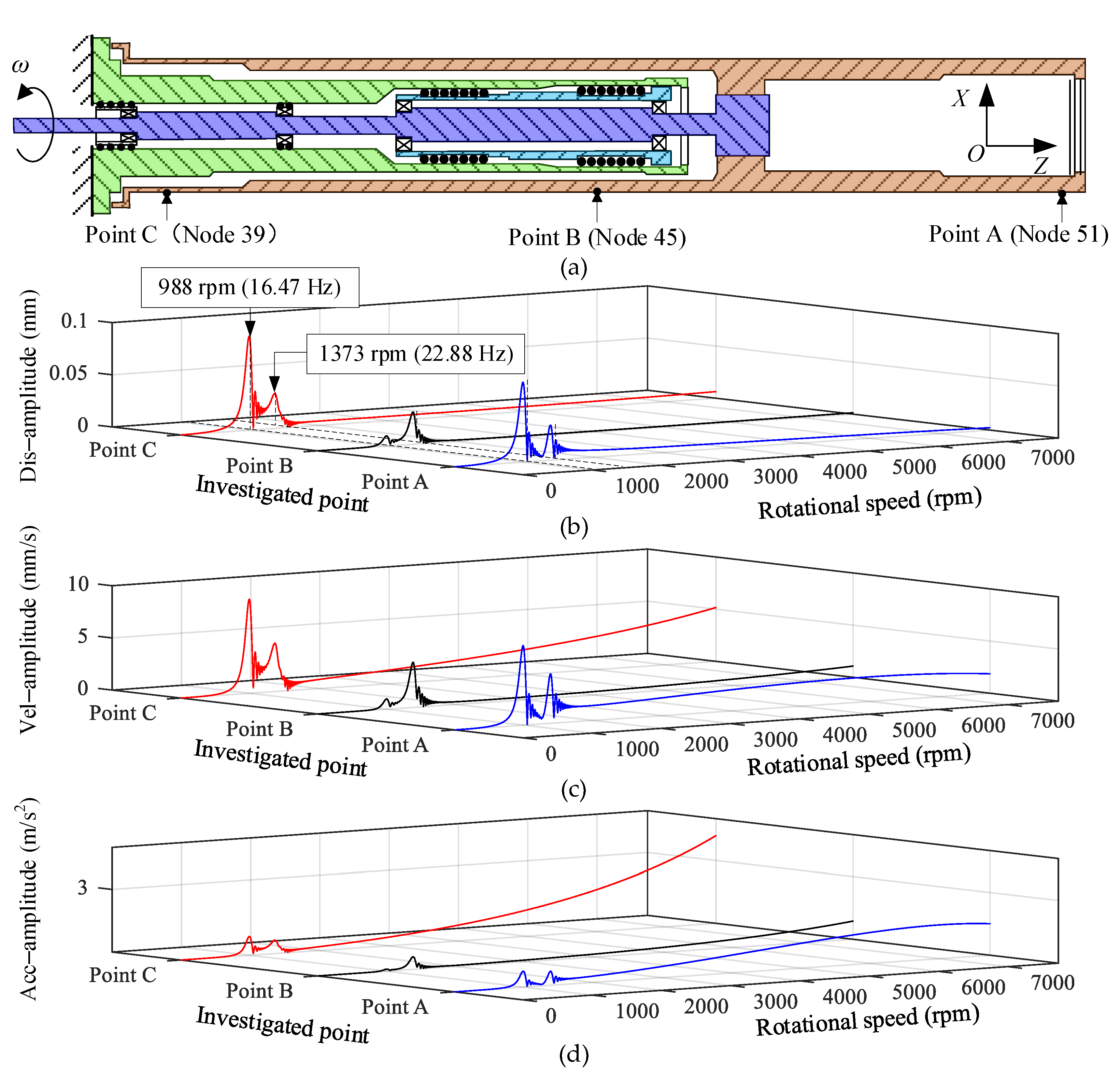
When the speed-up time is 60 s, the rotational speed of the winding rotor increases from 0 to 7730 rpm, and the displacement amplitudes of investigated point A (node 51), point B (node 45) and point C (node 39) in the X-axis direction were obtained through the simulation, respectively, as shown in Figure 11b. It can be found that the winding rotor passed through the first-order and second-order critical speed points during speeding up, and two critical speed points are 988 rpm and 1373 rpm, respectively.
In order to study the dynamic characteristics of the winding rotor during speeding up, the velocity amplitude and acceleration amplitude were further obtained, as shown in Figure 11c,d.
The displacement amplitude, velocity amplitude and the acceleration amplitude of the investigated points were analyzed in Figure 11, and the results show:
  • During speeding up, two critical speed points of the winding rotor have appeared. The first-order and second-order critical speed points are mainly caused by the flexible support of the rubber O-ring. Meanwhile, taking into account the influence of automatic centering of the winding rotor, the investigated points have a larger vibration displacement amplitude. However, due to the low rotational speed and the short excitation time of the residual unbalanced force acting on the winding rotor, the acceleration amplitude of the investigated points is relatively small;
  • As the rotational speed increases, the exciting force of the residual unbalance formed by the winding rotor becomes stronger, which causes the investigated points on the winding rotor to present a larger vibration displacement amplitude. As seen in Figure 11c,d, the velocity amplitude and acceleration amplitude of the three investigated points increase correspondingly. In addition, when the rotational speed of the rotor exceeds 2000 rpm and is less than 7730 rpm, the winding rotor has a small vibration amplitude and a high degree of stability.
To validate the correctness of simulation results and the proposed methods, a test measurement was carried out to obtain the vibration displacement amplitude of the winding rotor, whose structure and parameters were consistent with the simulation model shown in Figure 1.

3.1.2. Test Measurement

Before the test, the angular speed of the winding rotor increases at a constant angular acceleration by adjusting the control parameters of the motor, as shown in Figure 9.
The non-contact measurement device shown in Figure 10 was used to perform the vibration displacement test on the winding rotor. Certainly, the positions of measuring points on the winding rotor were consistent with investigated points in the simulation model shown in Figure 12a.
During data processing, due to a variety of interference effects, such as white noise, displacement signals obtained have a certain error. Therefore, in this paper, the FIR digital filter is designed by using the ripple Chebyshev method, and the signals were processed by the low-pass filter to enhance the signal-to-noise ratio.
When speed-up time is 50 s, 60 s and 70 s, respectively, the testing results are shown in Figure 12b–d. By studying the vibration amplitude curve obtained from the test, the following conclusions can be obtained.
  • The displacement amplitude of point B is smaller than that of point A and point C. It is mainly caused because the central position of the sleeve is supported by the supporting arm, as shown in Figure 12a. Due to the cantilever beam structure of the winding rotor and the supporting position of point B, the distance between point B and point C is larger than the distance between point B and point A, so the vibration displacement amplitude of point C is higher than that of point A near the first-order critical speed point;
  • When the speed-up time is 60 s, comparing the simulation results shown in Figure 10b and experimental results shown in Figure 12c, showed that they are in good agreement, which verifies the correctness of the developed model of the winding rotor in this paper. However, the vibration amplitudes of the measured points are larger than that of the investigated points. The main reason is that the large vibration amplitude of the measured points was mainly due to the cylindricity error of the testing position on the sleeve and the greater residual unbalance of the winding rotor. In the same speed-up time, the maximum displacement amplitude is still in point C near the first-order critical speed point. Comparing different speed-up times, as the speed-up time increases, the vibration amplitude increases correspondingly: 0.0915 mm (speed-up time 50 s), 0.0962 mm (speed-up time 60 s) and 0.0997 mm (speed-up time 70 s). Similarly, points B and point C have the same characteristics.
  • During speeding up, it can be found that the rotational speed passes through the first-order critical speed point of the winding rotor based on the response amplitude. However, the vibration amplitude caused by passing through the second-order critical speed point cannot be clearly identified from Figure 12. To further analyze the experimental data, the frequency analysis of vibration data for the measured point C is performed under the speed-up time of 50 s, and the spectrum diagram is shown in Figure 13.
As shown in Figure 13, there is a second critical speed point, and the corresponding speed is 1234.8 rpm, which is close to the simulation second-order speed 1373 rpm. Since the two critical speed points of the winding rotor are close and the vibration amplitude of the first critical speed point is larger than that of the second, the response amplitude caused by the second critical speed point is not obvious.

3.2. Discussion

During speeding up, the vibration amplitude of the winding rotor in point A (node 51) in the X direction was selected for investigation, comparison and discussion.

3.2.1. Support without Rubber O-rings and Support with Rubber O-rings

In the analysis model, the support without rubber O-rings only considers the action of the bearing, and ignores the rubber O-ring. So, the supporting stiffness coefficient of the rolling bearing is that of the support without rubber O-rings, and its damping effect is not considered.
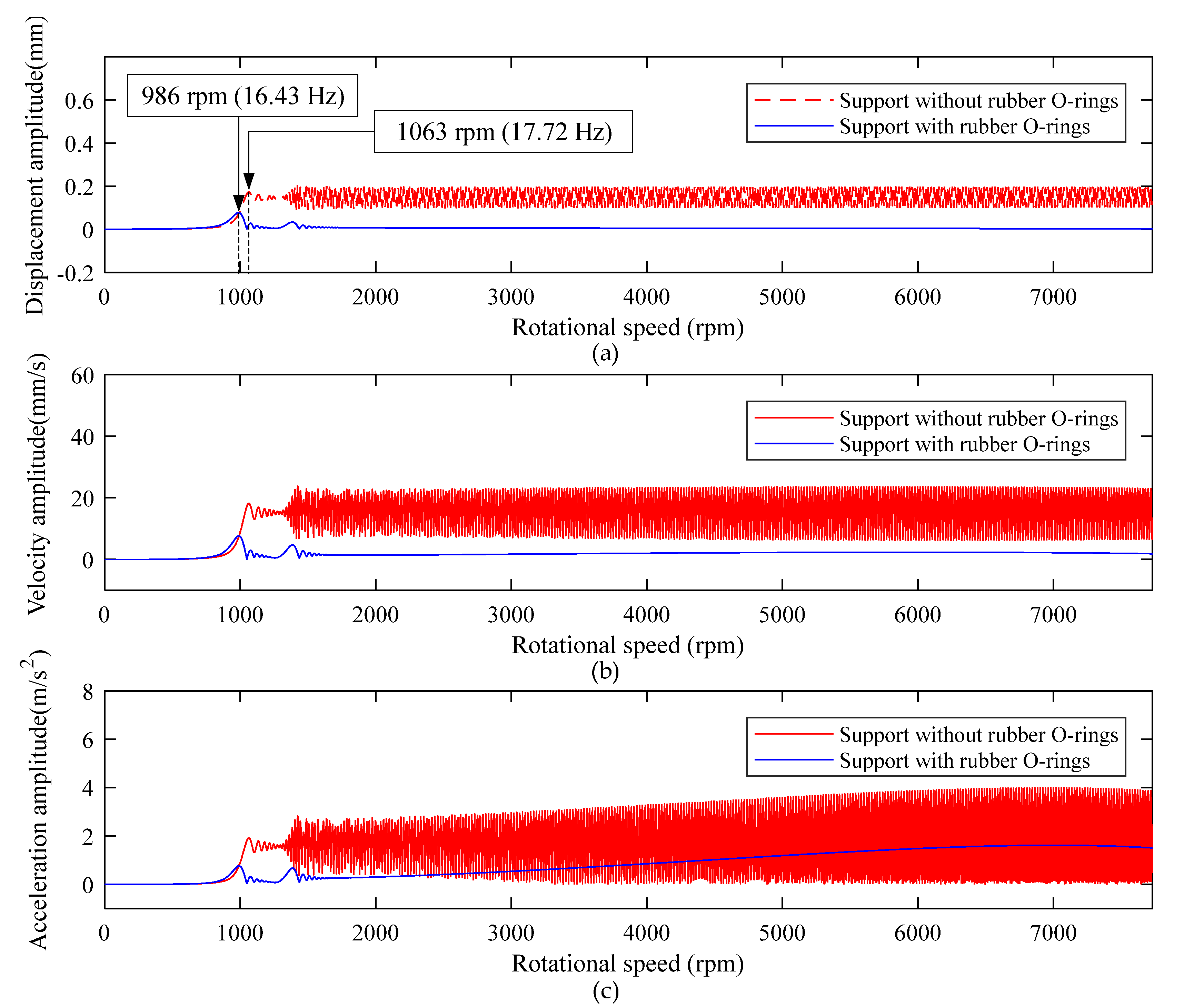
To understand the importance of support with rubber O-rings, especially in high-power and high-speed applications, the dynamic response of the winding rotor at point A was investigated under support without rubber O-rings and support with rubber O-rings, as shown in Figure 14.
Research on the dynamic characteristics of the winding rotor with support without rubber O-rings and support with rubber O-rings through the simulation, the results are as follows:
  • The multiple rubber O-rings are installed in groups to form flexible support, and its equivalent overall supporting stiffness coefficient could reach the order of 10 7 N/m, which is equal in the order of magnitude with the equivalent stiffness coefficient of the rolling bearings, as shown in Figure 8a. When the winding rotor adopts support with rubber O-rings, its first-order critical speed point is near 986 rpm. When the winding rotor adopts support without rubber O-rings, its first-order critical speed point is near 1063 rpm. The main reason for this is high stiffness through the interference connection, which leads to an increase in the critical speed of the rotor. In addition, when the rotational speed of the winding rotor is much lower than the first-order critical speed, the winding rotor with support without rubber O-rings and support with rubber O-rings both have relatively small vibration amplitude, as shown in Figure 14;
  • As the rotational speed increases, the residual unbalance force acting on the rotor, including centrifugal force, increases correspondingly, which leads to the heavy vibration of the winding rotor when the rotational speed passes through the critical speed range. Especially after passing through the second-order critical speed, the winding rotor with support without rubber O-rings has constant heavy vibration. Due to the heavy vibration after passing through the second-order critical speed point, the winding rotor cannot work anymore in the textile process;
  • When the winding rotor rotates within 7730 rpm, according to two different supports, the dynamic characteristics of the winding rotor are divided into two different parts by the first-order critical speed point. For the winding rotor with the support without rubber O-rings, as the residual unbalance force acting on the rotor increases, the displacement amplitude, velocity and acceleration amplitude of point A gradually increase. For the winding rotor with the support with rubber O-rings, the vibration amplitude increases slowly and the acceleration amplitude was stable after the rotational speed passing through the second-order critical speed point of the winding rotor;
  • By contrast, the winding rotor with support with rubber O-rings has a very attractive dynamic character to control the vibration of the rotor system when rotational speed passes through the critical speed range.

3.2.2. Different Supporting Stiffness and Damping Coefficients of Rubber O-rings

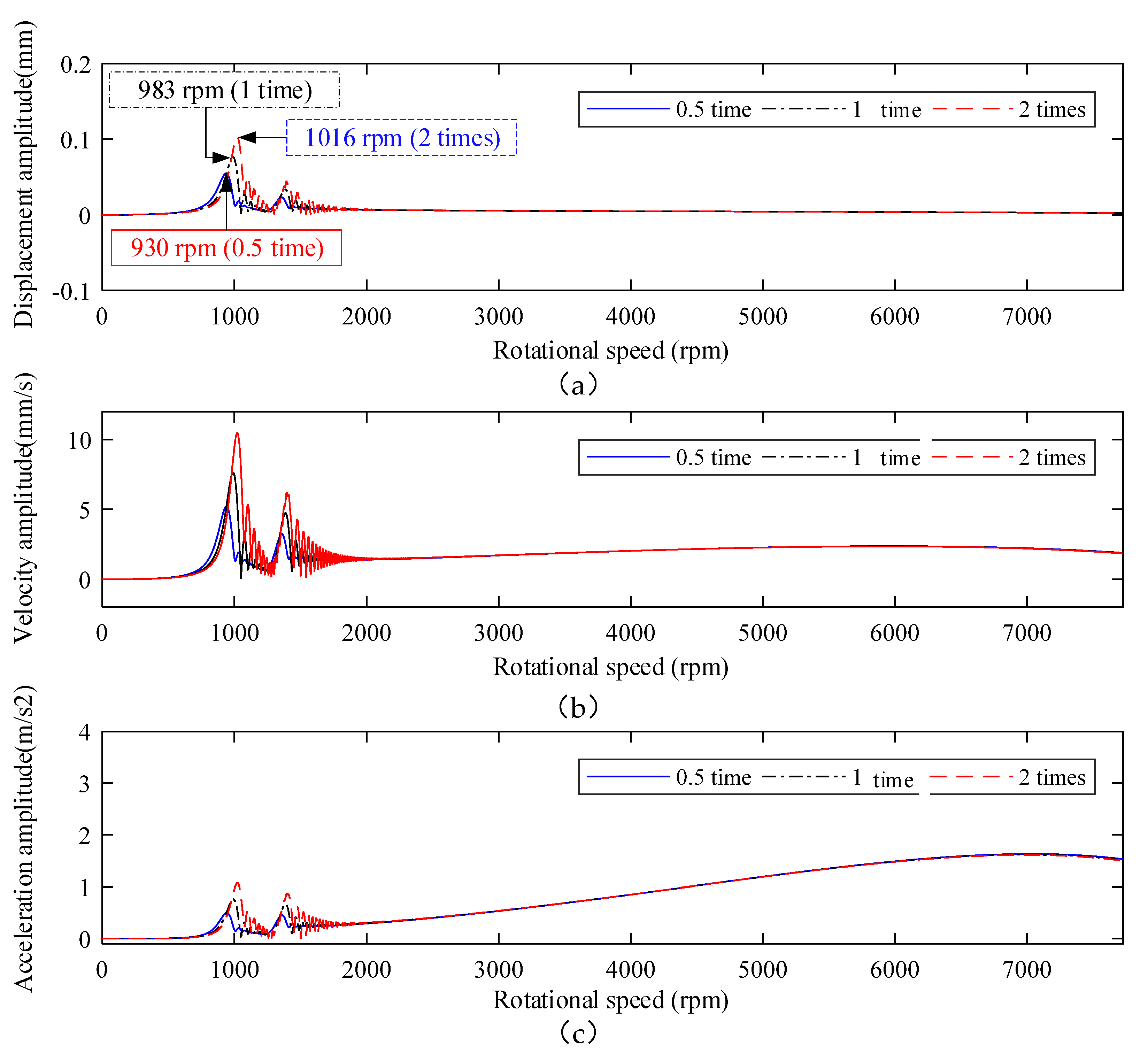
Based on the analysis in Section 3.2.1, the flexible support for the winding rotor is of significance to control its vibration. To obtain better performance of the rotor, the structure and process parameters of the rotor should be designed practically. In this section, the different coefficients of supporting parameters of the rubber O-rings in the flexible support were studied further. In practical application, the coefficients of the supporting parameter of the rubber O-ring can be obtained through changing the rubber material and number of rubber O-rings, as well as the structural parameters of the rubber O-ring. The dynamic response of the winding rotor was carried out under the original supporting parameters in Figure 7, 0.5 time and 2 times coefficients of the supporting parameters of the rubber O-ring, and the vibration amplitude-rotational speed curves are shown in Figure 15.
Through the study of the influence of different supporting stiffness and damping coefficients of rubber O-rings on the winding rotor, research results show as follows:
  • Since the rubber O-rings are installed on the shaft in parallel, the stiffness value of supporting rubber O-rings increases with the increase of their number. Therefore, the critical speed point of the rotor is increased correspondingly, as shown in Figure 15a;
  • Comparing with Figure 14, it can be seen that the flexible support effectively suppresses vibration of the winding rotor, and plays an important role in maintaining the system to pass through the critical speed points smoothly and rotate steadily in a wide working speed range. In addition, the winding rotor can rotate steadily in the wide working speed range under the equivalent coefficient of 0.5 time, 1 time and 2 times supporting parameters of the flexible support, which provides more rational choices for designing the flexible support structure and parameters.
  • Appropriately increasing the values of supporting stiffness can effectively improve the supporting capacity of the winding rotor, but it will increase the vibration amplitude of the system.

3.2.3. Different Speed-Up Times

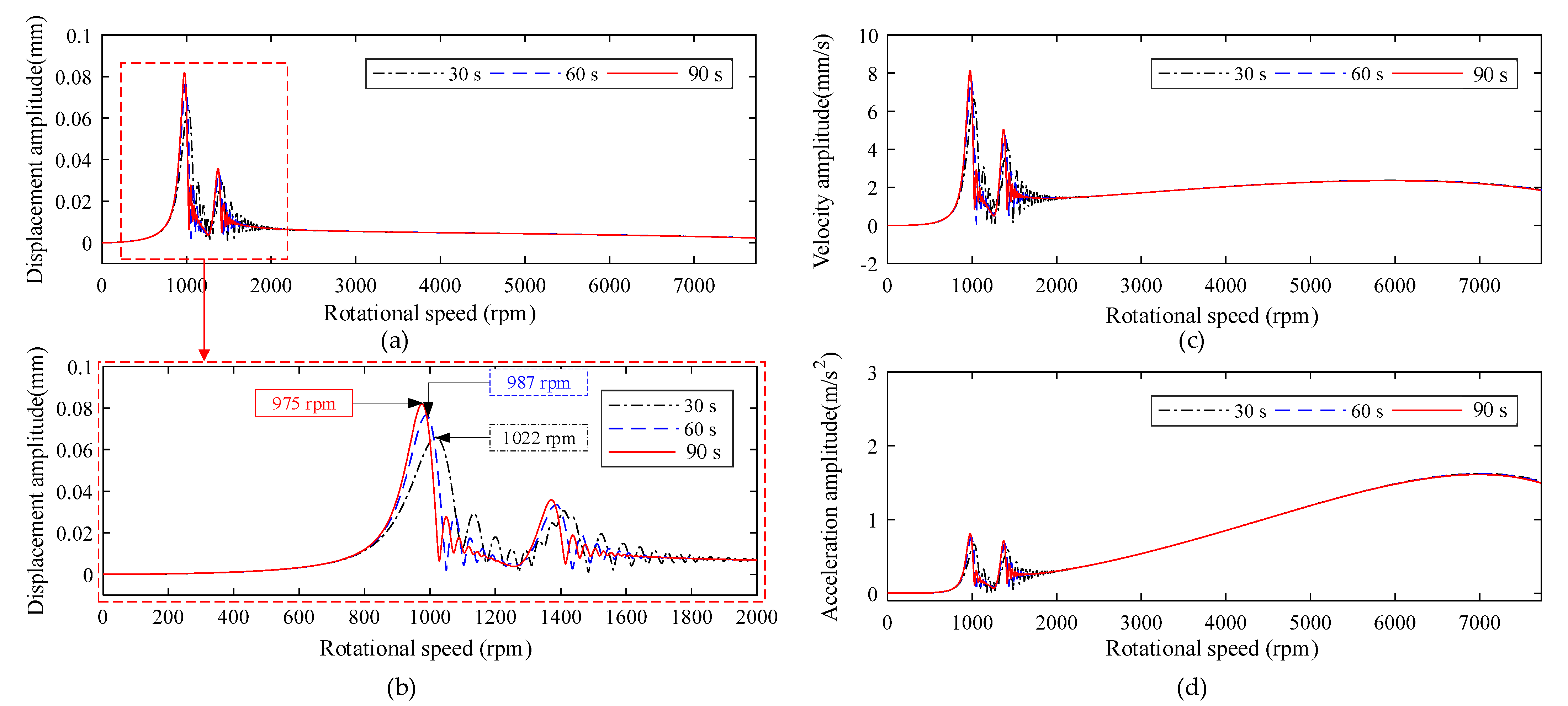
To steadily pass through the critical speed points of the winding rotor, there is another effective method where the speed-up time is shortened to make the winding rotor pass quickly through the critical speed range. Hence, this paper also discusses the influence of the speed-up time on the winding rotor dynamics, as shown in Figure 16.
Research on the dynamic characteristics of the winding rotor under different speed-up times through the simulation, shows results as follows:
  • During the rotational speed of the winding rotor passing through the critical speed of the winding rotor, when the speed-up time is short (30 s), the action time acting on the critical speed range is short, and the response amplitude is small. When the speed-up time increases (90 s), the action time that acts on the rotor’s critical speed range increases, that is, the action time that the external excitation force acts on the critical speed range increases, resulting in large amplitude and longer response time, as shown in Figure 16;
  • Figure 16d shows, by shortening the speed-up time, that the acceleration amplitude can be reduced effectively, or even be crossed in some critical speed points with weak vibration. This study lays a solid foundation for providing the reference to design the working speed range and avoid the rotor working near its critical speed point. However, the winding rotor needs to install a high-power motor to shorten the speed-up time.

4. Conclusions

The winding rotor is a complex system with a coupling structure. Considering the time-varying rotational speed and frequency-dependent supporting parameters, the system dynamic method is adopted to reveal the dynamic characteristics of the winding rotor.
The simulation results show that the flexible support with rubber O-rings can effectively reduce the unbalance response amplitude of the winding rotor, thereby ensuring that the rotor passes smoothly through the critical speed points, so that the winding rotor can rotate steadily in a wide working speed range.
The nonlinearity of material constitutive parameters and structure of the rubber O-ring results in the frequency-dependent characteristics of flexible support parameters. Different flexible support stiffness and damping parameters can be obtained by changing the rubber hardness, structural parameters and number of rubber rings. Through the selection of the number and type of rubber rings in the flexible support, the degree of reduction of the system amplitude can be controlled to satisfy the design requirements. It is one of the convenient methods to improve the design only by selecting the rubber O-rings.
In addition, properly shortening the speed-up time can make the rotor pass quickly through the critical speed points and effectively reduce the vibration amplitude, so as to provide the reference for reasonably determining the rotational speed range and designing working parameters. Of course, to shorten speed-up time means that a large capacity motor drive is required.
A vibration measurement method of the winding rotor was proposed, and the non-contact measurement device was also developed by using the optical displacement sensor of Keyence. The measuring device is not limited to the material on the surface of the measured object and the distance between the sensor and the measured object.
The simulation and measurement methods proposed in this paper, as well as the finding, can also be used for investigating and designing the other high-speed flexible support rotor.

5. Patents

The method and device of the experimental test were authorized by China National Intellectual Property Administration (ZL 2019 10360980.9, A Spindle vibration measurement device under whole process state of high-speed winding rotor).

Author Contributions

Conceptualization, Y.W., S.W. and X.M.; methodology, Y.W.; software, X.M.; validation, X.M., W.T. and S.L.; formal analysis, S.L. and X.Q.; investigation, W.T.; data curation, X.M.; writing—original draft preparation, X.M.; writing—review and editing, X.M. and S.L. All authors have read and agreed to the published version of the manuscript.

Funding

This research was funded by the National Key R&D Program of China, grant number 2017YFB1304000, and the Applied Foundation Research of China National Textile and Apparel Council, grant number J201504 and the Natural Science Foundation of Shanghai, grant number 16ZR1401900.

Data Availability Statement

Not applicable.

Conflicts of Interest

The authors declare no conflict of interest.

Nomenclature

A b cross-section area of beam element
C s damping matrix of system
C e gyroscopic matrix of beam element
c c o n damping of coupling connection
C contact global coupling matrix of contact damping
C Rubber global damping coupling matrix of rubber O-ring
C rubber damping matrix of beam element of rubber O-ring
c b y , c b z equivalent damping coefficient of the rolling bearing
c r i equivalent damping coefficient of rubber O-ring, i = 1 , 2 , 3
D outer diameter of beam element cross-section
d inner diameter of beam element cross-section
E elastic modulus of structure steel
e node coordinate arrays of beam element
F i , F j forces acting on the node masses m i and m j , respectively
F e generalized force array of beam element
F g gravity vector of system
F s generalized force array of system
G s gyroscopic moment matrix of system
G shear modulus of beam element
I second moment of inertia of beam element
i subscript, representing node i
K contact global coupling matrix of contact stiffness
K Rubber global stiffness coupling matrix of rubber O-ring
K rubber stiffness matrix of beam element of rubber O-ring
K transverse shear form factor
K e stiffness matrix of beam element
k b y , k b z equivalent damping coefficient of bearing
k c o n stiffness of coupling connection
k r i equivalent stiffness coefficient of rubber O-ring, i = 1 , 2 , 3
l unit length
M S mass matrix of system
M e mass matrix of beam element
[ M e c ] r o t a rotatory mass matrix
[ M e c ] t r a n s translational mass matrix
m i ,   m j masses of node i and j , respectively
s distance between node A and arbitrary point on the centerline
t time
t d end time during deceleration
t s end time during speeding up
t w end time during winding
U s , U ˙ s , U ¨ s generalized arrays of displacement, velocity, acceleration
u e , u ˙ e , u ¨ e generalized arrays of displacement, velocity and acceleration of element
u , u ˙ displacement and velocity of node in the x -axis direction
v , v ˙ displacement and velocity of node in the z -axis direction
x i , x ˙ i , x ¨ i displacement, velocity and acceleration of node i
θ x angular displacement around x -axis
θ z angular displacement around z -axis
Φ 1 , Φ 2 , Φ 3 ,   Φ 4 angular displacement interpolation functions
χ transverse shear effect
Ψ 1 , Ψ 2 , Ψ 3 , Ψ 4 linear displacement interpolation functions
ω rotating angular velocity of winding rotor
Ω rotating angular matrix of system
O X Y Z global coordinate frame
o x y z local coordinate frame in beam element

References

  1. Hung, J.P.; Lai, Y.L.; Luo, T.L.; Su, C.H. Analysis of the machining stability of a milling machine considering the effect of machine frame structure and spindle bearings: Experimental and finite element approaches. Int. J. Adv. Manuf. Tech. 2013, 68, 2393–2405. [Google Scholar] [CrossRef]
  2. Özsahin, O.; Özgüven, H.N.; Budak, E. Analytical Modeling of Asymmetric Multi-Segment Rotor—Bearing Systems with Timoshenko Beam Model Including Gyroscopic Moments. Comput. Struct. 2014, 144, 119–126. [Google Scholar] [CrossRef]
  3. Yu, P.C.; Zhang, D.Y.; Ma, Y.H.; Hong, J. Dynamic Modeling and Vibration Characteristics Analysis of the Aero-Engine Dual-Rotor System with Fan Blade Out. Mech. Syst. Signal Process. 2018, 106, 158–175. [Google Scholar] [CrossRef]
  4. Zhang, F.L.; Li, L.; Fan, Y.; Liu, J.Z. Dual-Connected Synchronized Switch Damping for Vibration Control of Bladed Disks in Aero-Engines. Appl. Sci. 2020, 10, 1478. [Google Scholar] [CrossRef] [Green Version]
  5. Liu, J.; Wang, C.; Luo, Z.W. Research Nonlinear Vibrations of a Dual-Rotor System with Nonlinear Restoring Forces. J. Braz. Soc. Mech. Sci. Eng. 2020, 42, 461. [Google Scholar] [CrossRef]
  6. Queguineur, M.; Bridel-Bertomeu, T.; Gicquel, L.Y.; Staffelbach, G. Large Eddy Simulations and Global Stability Analyses of an Annular and Cylindrical Rotor/Stator Cavity Limit Cycles. Phys. Fluids 2019, 31, 104109. [Google Scholar] [CrossRef]
  7. Xia, P.; Chen, H.; Liu, Z.S.; Ma, W.S.; Yang, B.F. Analysis of Whirling Motion for the Dynamic System of Floating Ring Seal and Rotor. Proc. Inst. Mech. Eng. Part J J. Eng. Tribol. 2019, 233, 1221–1235. [Google Scholar] [CrossRef]
  8. Chien, C.G.; Fung, R.F.; Tsai, C.L. Nonlinear Vibration of the Coupled Textile / Rotor System by Finite Difference Method. JSME Int. J. Ser. C 1999, 42, 273–280. [Google Scholar]
  9. Cveticanin, L. The Influence of the Reactive Force on the Motion of the Rotor on Which the Band Is Winding Up. J. Sound Vib. 1993, 167, 382–384. [Google Scholar] [CrossRef]
  10. Lund, J.W. The Stability of an Elastic Rotor in Journal Bearings with Flexible, Damped Supports. J. Appl. Mech. 1965, 87, 911–920. [Google Scholar] [CrossRef]
  11. Powell, J.W.; Tempest, M.C. A Study of High Speed Machines with Rubber Stabilized Air Bearings. J. Lubr. Technol. 1968, 90, 701–707. [Google Scholar] [CrossRef]
  12. Kazimierski, Z.; Jarzecki, K. Stability Threshold of Flexibly Supported Hybrid Gas Journal Bearings. J. Lubr. Technol. 1979, 101, 451–457. [Google Scholar] [CrossRef]
  13. Bttig, P.; Schiffmann, J. Data-Driven Model for the Dynamic Characteristics of O-Rings for Gas Bearing Supported Rotors. J. Appl. Mech. 2019, 86, 081003. [Google Scholar] [CrossRef]
  14. Wang, Y.X.; Zhang, L.J.; Hou, X.; Yan, J.; Li, S.J. A Dynamic Modeling Approach for the Winding Spindle During Start-up with a Coupled Flexible Support System. Text. Res. J. 2019, 90, 757–775. [Google Scholar] [CrossRef]
  15. Nelson, H. A Finite Rotating Shaft Element Using Timoshenko Beam Theory. J. Mech. Des. 1980, 102, 793–803. [Google Scholar] [CrossRef]
  16. Kalita, M.; Kakoty, K.S. Analysis of Whirl Speeds for Rotor-Bearing Systems Supported on Fluid Film Bearings. Mech. Syst. Signal. Process. 2004, 18, 1369–1380. [Google Scholar] [CrossRef]
  17. Dutt, J.K.; Nakra, B.C. Stability Characteristics of Rotating Systems with Journal Bearings on Viscoelastic Support. Mech. Mach. Theory 1996, 31, 771–779. [Google Scholar] [CrossRef]
  18. Nelson, H.D.; Mcvaugh, J.M. The Dynamics of Rotor-Bearing Systems Using Finite Elements. Trans. Am. Soc. Mech. Eng. J. Eng. Ind. 1976, 98, 593–600. [Google Scholar] [CrossRef]
  19. Zorzi, E.S.; Nelson, H.D. Finite Element Simulation of Rotor-Bearing Systems with Internal Damping. J. Eng. Gas. Turbines Power 1977, 99, 71–76. [Google Scholar] [CrossRef]
  20. Kang, Y.; Chang, Y.P.; Tsai, J.W.; Mu, L.H.; Chang, Y.F. An Investigation in Stiffness Effects on Dynamics of Rotor-Bearing-Foundation Systems. J. Sound Vib. 2000, 231, 343–374. [Google Scholar] [CrossRef] [Green Version]
  21. Abdesselam, L.; Guy, C. Study of Rotor Asymmetry Effects of an Induction Machine by Finite Element Method. J. Electr. Eng. Technol. 2011, 6, 342–349. [Google Scholar] [CrossRef] [Green Version]
  22. Taplak, H.; Parlak, M. Evaluation of Gas Turbine Rotor Dynamic Analysis Using the Finite Element Method. Measurement 2012, 45, 1089–1097. [Google Scholar] [CrossRef]
  23. Bin, G.; Li, X.; Wu, J.; Gao, J. Virtual Dynamic Balancing Method without Trial Weights for Multi-Rotor Series Shafting Based on Finite Element Model Analysis. J. Renew. Sustain. Energy 2014, 6, 130–136. [Google Scholar] [CrossRef]
  24. Lee, A.C.; Kang, Y.; Tsai, K.L.; Hsiao, K.M. Transient Analysis of an Asymmetric Rotor-Bearing System During Acceleration. J. Eng. Ind. 1992, 114, 465–475. [Google Scholar] [CrossRef]
  25. Lee, A.S.; Kim, B.O.; Kim, Y.C. A finite element transient response analysis method of a rotor-bearing system to base shock excitations using the state-space Newmark scheme and comparisons with experiments. J. Sound Vib. 2006, 297, 595–615. [Google Scholar] [CrossRef]
  26. Kim, B.S.; Lee, S.H.; Lee, M.G.; Ni, J.; Song, J.Y.; Lee, C.W. A comparative study on damage detection in speed-up and coast-down process of grinding spindle-typed rotor-bearing system. J. Mater. Process. Technol. 2007, 187, 30–36. [Google Scholar] [CrossRef]
  27. Yang, Q.; Li, L.; Zhao, Y.; Shu, P. Experimental Measurement of Axial Clearance in Scroll Compressor Using Eddy Current Displacement Sensor. Proc. Inst. Mech. Eng. Part C J. Mech. Eng. Sci. 2008, 222, 1315–1320. [Google Scholar] [CrossRef]
  28. Mirzaei, M.; Ripka, P.; Vyhnanek, J.; Chirtsov, A.; Grim, V. Rotational Eddy Current Speed Sensor. IEEE Trans. Magn. 2019, 55, 1–10. [Google Scholar] [CrossRef]
  29. Rao, J.S.; Shiau, N.T.; Chang, R.J. Theoretical Analysis of Lateral Response Due to Torsional Excitation of Geared Rotors. Mech. Mach. Theory 1998, 33, 761–783. [Google Scholar] [CrossRef]
  30. Wu, J.J. Free Vibration Analysis of Beams Carrying a Number of Two-Degree-of-Freedom Spring-Damper-Mass Systems. Finite Elem. Anal. Des. 2004, 40, 363–381. [Google Scholar] [CrossRef]
  31. Chiang, H.W.; Hsu, C.N.; Tu, S.H. Rotor-Bearing Analysis for Turbomachinery Single- and Dual-Rotor Systems. J. Propuls. Power 2004, 20, 1096–1104. [Google Scholar] [CrossRef]
  32. Chen, G. A New Rotor-Ball Bearing-Stator Coupling Dynamics Model for Whole Aero-Engine Vibration. J. Vib. Acoust. 2009, 131, 061009. [Google Scholar] [CrossRef] [Green Version]
  33. Newmark, N.M. A Method of Computation for Structural Dynamics. J. Eng. Mech. Div. ASCE 1959, 85, 67–94. [Google Scholar] [CrossRef]
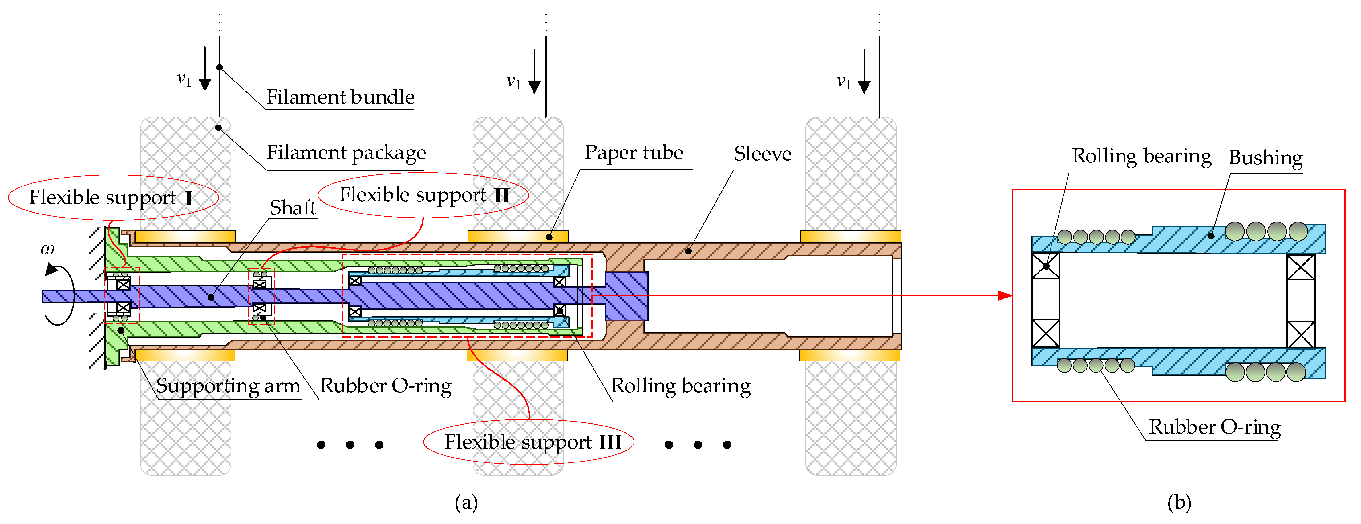
Figure 1. Layout of main structure of the winding rotor. (a) Winding rotor, where I II III denote the flexible supports with different rubber O-rings, respectively; (b) flexible support structure.
Applsci 11 08124 g001
Figure 2. Diagram of the single cycle of winding task.
Applsci 11 08124 g002
Figure 3. Finite element model of the winding rotor.
Applsci 11 08124 g003
Figure 4. Cylindrical shaft beam element.
Applsci 11 08124 g004
Figure 5. Spring-mass-damping system.
Applsci 11 08124 g005
Figure 6. Supporting element of the rubber O-ring. (a) Flexible support; (b) equivalent linear spring-damping model.
Applsci 11 08124 g006
Figure 7. The curves of supporting stiffness and supporting damping of rubber O-ring. (a) Equivalent supporting stiffness curve; (b) equivalent supporting damping curve.
Applsci 11 08124 g007
Figure 8. Rolling bearing unit. (a) Rolling bearing; (b) equivalent spring-damping model.
Applsci 11 08124 g008
Figure 9. Relationship between the variation of the angular speed and the time in the Newmark method.
Applsci 11 08124 g009
Figure 10. Experimental test of the winding rotor. (a) Experimental scheme; (b) measuring device.
Applsci 11 08124 g010
Figure 11. Dynamic response of different investigated points in the X direction under the speed-up time of 60 s. (a) Investigated points on the winding rotor; (b) displacement amplitude curve; (c) velocity amplitude curve; (d) acceleration amplitude curve.
Applsci 11 08124 g011
Figure 12. Testing results of the winding rotor under different speed-up times (a)Measuring points on the winding rotor; (b) speed-up time is 50 s; (c) speed-up time is 60 s; (d) speed-up time is 70 s.
Applsci 11 08124 g012
Figure 13. Amplitude-frequency characteristics at the measuring point C under speed-up time of 50 s.
Applsci 11 08124 g013
Figure 14. Dynamic response of point A (node 51) of support without rubber O-rings and support with rubber O-rings under the speed-up time of 60 s. (a) Displacement amplitude curve; (b) velocity amplitude curve; (c) acceleration amplitude curve.
Applsci 11 08124 g014
Figure 15. Dynamic response of investigated point A (node 51) of different supporting stiffness and damping coefficients of the rubber O-ring under the speed-up time of 60 s. (a) Displacement amplitude; (b) velocity amplitude; (c) acceleration amplitude.
Applsci 11 08124 g015
Figure 16. Dynamic response of investigated point A (node 51) of different acceleration speed-up times. (a) Displacement amplitude curve; (b) local enlarged drawing of Figure 16a; (c) velocity amplitude curve; (d) acceleration amplitude curve.
Applsci 11 08124 g016
Table 1. The instruments’ parameters used in the measurement device.
IDTypeModelSensitivity
1Keyence digital micrometerLS-9000±2 μm
2LMS SCADAS MobileSCM201V/
Table 2. Parameters of the high-speed winding rotor.
IDLabelValueUnit
1Supporting arm length1230(mm)
2Shaft length1340(mm)
3Sleeve length1780(mm)
4Outer diameter of sleeve107(mm)
5Interference coupling length75(mm)
6Bearing support span between Ⅰ and Ⅱ380(mm)
7Bearing support span Ⅲ400(mm)
8Support flexible Ⅰ15(mm)
9Support flexible Ⅱ30(mm)
10Support flexible Ⅲ505(mm)
11Maximum rotational speed of winding rotor7730(rpm)
12Number of rear bearings2(set)
13Number of front bearings2(set)
14Mass of shaft8.66(kg)
15Mass of sleeve47.19(kg)
16Mass of supporting arm19.38(kg)
17Mass of support flexible Ⅰ1.6(kg)
18Mass of support flexible Ⅱ3.0(kg)
19Mass of support flexible Ⅲ4.5(kg)
20Unbalance of node 301.42 × 10⁻⁵(kg·m)
21Unbalance of node 467.41 × 10⁻⁵(kg·m)
Publisher’s Note: MDPI stays neutral with regard to jurisdictional claims in published maps and institutional affiliations.